EP1396410A1 - Zweiachsiges Antriebsaggregat für Schienenfahrzeuge - Google Patents
Zweiachsiges Antriebsaggregat für Schienenfahrzeuge Download PDFInfo
- Publication number
- EP1396410A1 EP1396410A1 EP03019822A EP03019822A EP1396410A1 EP 1396410 A1 EP1396410 A1 EP 1396410A1 EP 03019822 A EP03019822 A EP 03019822A EP 03019822 A EP03019822 A EP 03019822A EP 1396410 A1 EP1396410 A1 EP 1396410A1
- Authority
- EP
- European Patent Office
- Prior art keywords
- drive unit
- axle
- unit according
- joint
- drive
- Prior art date
- Legal status (The legal status is an assumption and is not a legal conclusion. Google has not performed a legal analysis and makes no representation as to the accuracy of the status listed.)
- Granted
Links
- 229920001971 elastomer Polymers 0.000 claims description 5
- 239000000806 elastomer Substances 0.000 claims description 5
- 238000006243 chemical reaction Methods 0.000 description 12
- 230000006835 compression Effects 0.000 description 2
- 238000007906 compression Methods 0.000 description 2
- 238000010521 absorption reaction Methods 0.000 description 1
- 238000010276 construction Methods 0.000 description 1
- 238000013016 damping Methods 0.000 description 1
- 230000000694 effects Effects 0.000 description 1
- 239000000725 suspension Substances 0.000 description 1
Images


Classifications
-
- B—PERFORMING OPERATIONS; TRANSPORTING
- B61—RAILWAYS
- B61F—RAIL VEHICLE SUSPENSIONS, e.g. UNDERFRAMES, BOGIES OR ARRANGEMENTS OF WHEEL AXLES; RAIL VEHICLES FOR USE ON TRACKS OF DIFFERENT WIDTH; PREVENTING DERAILING OF RAIL VEHICLES; WHEEL GUARDS, OBSTRUCTION REMOVERS OR THE LIKE FOR RAIL VEHICLES
- B61F3/00—Types of bogies
- B61F3/02—Types of bogies with more than one axle
- B61F3/04—Types of bogies with more than one axle with driven axles or wheels
-
- B—PERFORMING OPERATIONS; TRANSPORTING
- B61—RAILWAYS
- B61C—LOCOMOTIVES; MOTOR RAILCARS
- B61C9/00—Locomotives or motor railcars characterised by the type of transmission system used; Transmission systems specially adapted for locomotives or motor railcars
Definitions
- the invention relates to a two-axis drive unit for a bogie of a rail vehicle according to the Preamble of claim 1.
- DE-A 32 32 939 a further type of Known as a pendulum, which is not on the bogie, but on the body of the Rail vehicle is attached.
- each axle has its own axle drive and one own drive via one cardan shaft each; the two Drives are therefore connected in parallel.
- a torque arm is attached to the supports pendulum arranged between the two axes.
- the torque supports also Transfer traction from the axles to the body.
- the two are Axially strained, d. H. they have a common Drive on, the first axle drive via a cardan shaft and also via an intermediate cardan shaft drives the second axle gear. Both axle drives are thus connected in series in terms of drive and via wheels and braced against each other. This results in also opposite reaction moments of the axle gear what has an advantageous effect because the two opposite moments via the common torque arm compensate. There is no mutual tension of the two gears.
- the torque arm consists of two parallel to each other arranged handlebars - symmetrical to the one in the middle Cardan shaft - the ends of the handlebars are direct connected to the final drives.
- the handlebars are designed as triangular links, d. H. they have a single joint at one end and at the other end a double or double joint on, over which they are connected to the gearbox.
- Double joint acts as a pair of forces, which is the reaction moment picks up and over the handlebars and at the other end arranged single joint supports on the other axis.
- the handlebars arranged in the opposite direction, d. H. on everyone Axle gear is a double joint of one and one Single joint of the other handlebar arranged. This gives there is even support for the reaction torque also when changing direction, d. H. Change of direction the reaction moment.
- the two are Articulation points of the double joint vertically one above the other arranged.
- the handlebars can be one Follow the swiveling of the axes.
- the two pivot points of the double joint as far apart as possible lie. This will attack those in the joints Forces to absorb the reaction moment reduced.
- the joints are designed as elastomer joints, d. H. on the one hand they are damping and on the other hand they are sufficient agile and compliant. It is also advantageous if the Joints of the double joint as spherical elastomer joints are trained to the pivoting movement already mentioned to allow the handlebar.
- the single joint has different in the direction of travel and across the direction of travel Spring stiffness on: in the direction of travel the spring stiffness is relatively low, d. H. the joint is soft while it's a relative in the direction of the wheel axles has high spring stiffness, d. H. is hard trained. This can be done through appropriate training and metallic Inserts in the elastomer joint are made possible.
- the Distance between the single joint and the wheel axle if possible be small. This has the advantage of being stressed of the single joint is reduced and the reaction moment is supported as directly as possible on the axis.
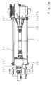
- Fig. 1 shows a two-axis drive unit 1 for a bogie, not shown, of a rail vehicle, in particular a diesel engine Rail vehicle.
- the unit 1 has two axes 2, 3 on each of which an axle drive 4, 5 is mounted is.
- the axle drive 5 or the axis 3 is a first propeller shaft 6 (drive shaft) driven.
- Between the axle drives 3, 4 is for driving the axle drive 4 another cardan shaft 7 (intermediate shaft) arranged, which a part of the drive power of the drive shaft 6 transmits the axle drive 4 and thus drives the axle 2.
- At the ends of axes 2 and 3 there are non-rotatable drive wheels 8, 9 arranged, the tensile force on a Transfer rail 10.
- the drive unit 1 is thus due to the two drives connected in series longitudinally clamped via the intermediate shaft 7 and the rail 10.
- the driver 12 is designed as a so-called wishbone, d. H. it has three articulation points 14, 15, 16, which as Joints are formed.
- the handlebar 12 thus engages an end designed as a fork 12a, 12b over the joints 14, 15 (double joint) on the axle gear 4 and with his other end 12c via the single joint 16 on the axle drive 5 on.
- the two joints 14, 15 are perpendicular in a distance a (i.e. perpendicular to the rail 10) above one another arranged.
- the distance of the joint 16 from the center line axis 3 is marked with b.
- the handlebar 13 has the same structure as a wishbone as the handlebar 12, but it is like in the opposite direction the handlebar 12 is arranged and fixed, d. H. he is opposite the handlebar 12 rotated 180 degrees about its vertical axis y.
- the double joint 14 ', 15' of the handlebar 13 is thus on the axle drive 5 and the single joint 16 'is on the axle drive 4 arranged. All joints 14, 15, 16 and 14 ', 15' and 16 'are preferably designed as elastomer joints and thus have a limited operating conditions adapted mobility and elasticity.
- the two Double joints 14, 15 and 14 ', 15' are preferably as spherical elastomeric joints designed so that pivoting the handlebar 12 by a perpendicular through the two Joints 14, 15 extending axis g is possible.
- An analog one Swiveling applies to the handlebar 13.
- the spring stiffness of the individual joint 16 or 16 ' is lower in the direction of travel X than transverse to the direction of travel, d. H. towards Z (see Fig. 1b). Since axes 3, 4, z. B. when cornering, change their angular position to each other, the distance between the joints 14, 16 also changes - therefore the joint 16 is designed to be soft in the direction of travel X, d. H. it has a relatively large travel. In Transverse direction Z is the joint 16 and also the joint 16 ' relatively hard, d. H. trained with a short travel. You can achieve these different spring stiffnesses in directions perpendicular to each other through metallic, roof-shaped deposits, such as that in Fig. 1b for the joint 16 is indicated.
- the function of the torque arm 11 is as follows: Due to the longitudinal bracing of the two axes 2, 3 result opposite reaction moments on the axle drives 4, 5.
- the reaction torque of the axle drive 4 is in the two joints 14, 15 and added to the handlebar 12 initiated. It is based on the single joint 16 on Axle gear 5 or on axis 3. The same applies to the reaction torque of the axle drive 5 - it is based Via the handlebar 13 on the axle drive 4 or on the axle 2 from.
- the distance a between the joints 14 and 15 (this also applies to the distance between the joints 14 ', 15') should, if possible be large, the smaller the forces for absorption the reaction moment in the joints 14, 15 or 14 ', 15'.
- the distance b of the joint 16 from the center line the axis 3 should be as low as possible, the lower becomes the lever arm acting on the axle drive 5.
Landscapes
- Engineering & Computer Science (AREA)
- Mechanical Engineering (AREA)
- Transportation (AREA)
- Automatic Cycles, And Cycles In General (AREA)
- Springs (AREA)
- Machines For Laying And Maintaining Railways (AREA)
- Steering Controls (AREA)
Abstract
Description
Es zeigen:
- Fig. 1
- eine Seitenansicht eines zweiachsigen Antriebsaggregats mit Drehmomentstütze,
- Fig. 1a
- eine Draufsicht auf das Antriebsaggregat gemäß Fig. 1 und
- Fig. 1b
- eine Seitenansicht des Antriebsaggregates gemäß Fig. 1.
- 1
- Antriebsaggregat
- 2
- Achse
- 3
- Achse
- 4
- Achsgetriebe
- 5
- Achsgetriebe
- 6
- Antriebswelle
- 7
- Zwischenwelle
- 8
- Antriebsrad
- 9
- Antriebsrad
- 10
- Schiene
- 11
- Drehmomentstütze
- 12
- Lenker
- 13
- Lenker
- 14
- Gelenk (Doppelgelenk)
- 15
- Gelenk (Doppelgelenk)
- 16
- Gelenk (Einzelgelenk)
Claims (11)
- Zweiachsiges Antriebsaggregat (1) für ein Drehgestell eines Schienenfahrzeuges, wobei jeder der beiden Achsen (2, 3) ein über eine Drehmomentstütze abstützbares Achsegetriebe (4, 5) zugeordnet ist, dadurch gekennzeichnet, dass die beiden Achsgetriebe (4, 5) gegenseitig durch eine gemeinsame Drehmomentstütze (11) abgestützt sind.
- Antriebsaggregat nach Anspruch 1, dadurch gekennzeichnet, dass die beiden Achsen (2, 3) einen gemeinsamen Antrieb (6) aufweisen und die Achsgetriebe (4, 5) über eine Zwischenwelle (7) längsverspannt sind.
- Antriebsaggregat nach Anspruch 1 oder 2, dadurch gekennzeichnet, dass die Drehmomentstütze (11) aus zwei parallel zueinander angeordneten Lenkern (12, 13) besteht, die mit den Achsgetrieben (4, 5) verbunden sind.
- Antriebsaggregat nach Anspruch 3, dadurch gekennzeichnet, dass die Lenker als Dreieckslenker (12, 13) mit je drei Anlenkpunkten (14, 15, 16) ausgebildet und über ein Einzelgelenk (16) an dem einen (5) und über ein Doppelgelenk (14, 15) an dem anderen Achsgetriebe (4) angelenkt sind.
- Antriebsaggregat nach Anspruch 3 oder 4, dadurch gekennzeichnet, dass die Lenker (12, 13), in Fahrtrichtung X gesehen, in entgegengesetzter Richtung zueinander angeordnet sind.
- Antriebsaggregat nach Anspruch 4 oder 5, dadurch gekennzeichnet, dass die beiden Anlenkpunkte des Doppelgelenkes (14, 15) an einem Achsgetriebe (4) senkrecht übereinander angeordnet sind.
- Antriebsaggregat nach Anspruch 6, dadurch gekennzeichnet, dass die beiden übereinander angeordneten Anlenkpunkte (14, 15) einen möglichst großen Abstand a aufweisen.
- Antriebsaggregat nach einem der Ansprüche 3 bis 7, dadurch gekennzeichnet, dass die Anlenkpunkte (14, 15, 16; 14', 15', 16') als Elastomergelenke ausgebildet sind.
- Antriebsaggregat nach Anspruch 4, 5, 6 oder 7, dadurch gekennzeichnet, dass die Anlenkpunkte (14, 15) des Doppelgelenkes als sphärische Elastomergelenke ausgebildet sind.
- Antriebsaggregat nach Anspruch 8 oder 9, dadurch gekennzeichnet, dass das Einzelgelenk (16), in Fahrtrichtung X gesehen, eine geringere Federsteifigkeit aufweist als quer zur Fahrtrichtung.
- Antriebsaggregat nach einem der Ansprüche 4 bis 10, dadurch gekennzeichnet, dass das Einzelgelenk (16) einen möglichst geringen Abstand b zur Radachse (3) des Achsgetriebes (5) aufweist, an dem es befestigt ist.
Applications Claiming Priority (2)
| Application Number | Priority Date | Filing Date | Title |
|---|---|---|---|
| DE10241013A DE10241013A1 (de) | 2002-09-05 | 2002-09-05 | Zweiachsiges Antriebsaggregat für Schienenfahrzeuge |
| DE10241013 | 2002-09-05 |
Publications (2)
| Publication Number | Publication Date |
|---|---|
| EP1396410A1 true EP1396410A1 (de) | 2004-03-10 |
| EP1396410B1 EP1396410B1 (de) | 2006-02-01 |
Family
ID=31502387
Family Applications (1)
| Application Number | Title | Priority Date | Filing Date |
|---|---|---|---|
| EP03019822A Expired - Lifetime EP1396410B1 (de) | 2002-09-05 | 2003-08-30 | Zweiachsiges Antriebsaggregat für Schienenfahrzeuge |
Country Status (3)
| Country | Link |
|---|---|
| EP (1) | EP1396410B1 (de) |
| AT (1) | ATE316889T1 (de) |
| DE (2) | DE10241013A1 (de) |
Citations (4)
| Publication number | Priority date | Publication date | Assignee | Title |
|---|---|---|---|---|
| DE598957C (de) * | 1932-03-04 | 1934-06-22 | Curt Stedefeld Dipl Ing | Anordnung der Drehmomentstuetzen fuer zwei benachbarte Treibachsen |
| DE1150402B (de) * | 1956-09-22 | 1963-06-20 | Inventio Ag | Zweiachsiges Triebdrehgestell fuer Schienenfahrzeuge |
| EP0072535A1 (de) * | 1981-08-14 | 1983-02-23 | Thyssen Industrie Ag | Triebdrehgestell für ein Schienenfahrzeug |
| DE10049819A1 (de) * | 2000-10-09 | 2002-04-18 | Siemens Ag | Drehgestell eines Triebfahrzeugs |
Family Cites Families (5)
| Publication number | Priority date | Publication date | Assignee | Title |
|---|---|---|---|---|
| DE1855443U (de) * | 1960-12-05 | 1962-07-26 | Waggonfabrik Ag | Vorrichtung zur abstuetzung von ueber gelenkwellen od. dgl. angetriebenen seitlich in radnaehe angeordneten achsgetrieben mit sich gegenseitig abstuetzenden momentenstuetzen bei schienenfahrzeugen mit gerader anzahl von treibachsen. |
| DE3232939C2 (de) * | 1982-09-04 | 1984-10-25 | Thyssen Industrie Ag, 4300 Essen | Abstützvorrichtung für Drehmomentstützen von Achsgetriebegehäusen bei Schienentriebfahrzeugen |
| JPH03501008A (ja) * | 1988-08-30 | 1991-03-07 | エス イー ゲー シユヴアイツエリツシエ インズストリー―ゲゼルシヤフト | 高速軌道車両用のボギー台車 |
| DE4143519C2 (de) * | 1991-02-27 | 1998-10-29 | Abb Daimler Benz Transp | Vorrichtung zur Übertragung von Traktionskräften in Drehgestellen von Schienenfahrzeugen |
| DE4424884A1 (de) * | 1994-07-14 | 1996-01-18 | Siemens Schienenfahrzeugtech | Laufwerk für Schienenfahrzeuge |
-
2002
- 2002-09-05 DE DE10241013A patent/DE10241013A1/de not_active Withdrawn
-
2003
- 2003-08-30 EP EP03019822A patent/EP1396410B1/de not_active Expired - Lifetime
- 2003-08-30 AT AT03019822T patent/ATE316889T1/de active
- 2003-08-30 DE DE50302320T patent/DE50302320D1/de not_active Expired - Lifetime
Patent Citations (4)
| Publication number | Priority date | Publication date | Assignee | Title |
|---|---|---|---|---|
| DE598957C (de) * | 1932-03-04 | 1934-06-22 | Curt Stedefeld Dipl Ing | Anordnung der Drehmomentstuetzen fuer zwei benachbarte Treibachsen |
| DE1150402B (de) * | 1956-09-22 | 1963-06-20 | Inventio Ag | Zweiachsiges Triebdrehgestell fuer Schienenfahrzeuge |
| EP0072535A1 (de) * | 1981-08-14 | 1983-02-23 | Thyssen Industrie Ag | Triebdrehgestell für ein Schienenfahrzeug |
| DE10049819A1 (de) * | 2000-10-09 | 2002-04-18 | Siemens Ag | Drehgestell eines Triebfahrzeugs |
Also Published As
| Publication number | Publication date |
|---|---|
| DE10241013A1 (de) | 2004-03-11 |
| EP1396410B1 (de) | 2006-02-01 |
| ATE316889T1 (de) | 2006-02-15 |
| DE50302320D1 (de) | 2006-04-13 |
Similar Documents
| Publication | Publication Date | Title |
|---|---|---|
| DE69404031T2 (de) | Aus mehreren modulen zusammengestelltes und durch eine zusammengesetzte verbindung gekoppeltes fahrzeug | |
| AT395139B (de) | Fahrgestell fuer ein schienenfahrzeug | |
| DE3331559A1 (de) | Achssteuerung fuer schienenfahrzeuge | |
| DE19623936C1 (de) | Lagerung eines Achsgetriebegehäuses eines Kraftfahrzeuges | |
| DE102012022889A1 (de) | Stabilisatoranordnung für eine Radaufhängung von Kraftfahrzeugen | |
| DE4143519C2 (de) | Vorrichtung zur Übertragung von Traktionskräften in Drehgestellen von Schienenfahrzeugen | |
| DE3433312A1 (de) | Aufhaengung der lenkbaren triebachse eines gelaendegaengigen zugfahrzeuges | |
| DE3507433A1 (de) | Unabhaengiges aufhaengesystem fuer die raeder, insbesondere hinterraeder, eines kraftfahrzeuges | |
| DE1957145B2 (de) | Einzelradaufhängung für die Hinterräder an Kraftfahrzeugen | |
| DE1530783B2 (de) | Hinterachsaufhangung fur Kraftfahr zeuge mit einer Starrachse | |
| EP0580995B1 (de) | Aus mindestens zwei Fahrzeugen bestehender spurgeführter Fahrzeugverband mit gesteuerten Einzelradsatzfahrwerken | |
| EP0137931B1 (de) | Antriebsaggregat für Schienenfahrzeuge | |
| DE1530023A1 (de) | Fahrzeug | |
| DE3705417C2 (de) | ||
| DE10041200B4 (de) | Federbein mit Sturzausgleich | |
| DE2062926C3 (de) | Gelenkiger Fahrzeugrahmen, insbesondere für geländegängige Fahrzeuge | |
| DE2837302C2 (de) | ||
| EP1396410B1 (de) | Zweiachsiges Antriebsaggregat für Schienenfahrzeuge | |
| EP4275928A1 (de) | Fahrgestell für ein kraftfahrzeug | |
| EP0485732A2 (de) | Baufahrzeug, vorzugsweise Radlader mit Knickrahmenlenkung | |
| DE3115611A1 (de) | Radaufhaengung fuer ein kraftfahrzeug | |
| EP2559605A2 (de) | Schienenfahrzeug mit einstufiger Federung | |
| DE19935160A1 (de) | Vorrichtung zur Erhöhung der Lenkfähigkeit getriebener Achsen | |
| EP0756981A1 (de) | Vorderachse für ein Kraftfahrzeug | |
| DE102013210235A1 (de) | Drehmomentstütze für ein Schienenfahrzeug |
Legal Events
| Date | Code | Title | Description |
|---|---|---|---|
| PUAI | Public reference made under article 153(3) epc to a published international application that has entered the european phase |
Free format text: ORIGINAL CODE: 0009012 |
|
| AK | Designated contracting states |
Kind code of ref document: A1 Designated state(s): AT BE BG CH CY CZ DE DK EE ES FI FR GB GR HU IE IT LI LU MC NL PT RO SE SI SK TR |
|
| AX | Request for extension of the european patent |
Extension state: AL LT LV MK |
|
| 17P | Request for examination filed |
Effective date: 20040113 |
|
| 17Q | First examination report despatched |
Effective date: 20040506 |
|
| AKX | Designation fees paid |
Designated state(s): AT DE FR IT |
|
| GRAP | Despatch of communication of intention to grant a patent |
Free format text: ORIGINAL CODE: EPIDOSNIGR1 |
|
| GRAS | Grant fee paid |
Free format text: ORIGINAL CODE: EPIDOSNIGR3 |
|
| GRAA | (expected) grant |
Free format text: ORIGINAL CODE: 0009210 |
|
| AK | Designated contracting states |
Kind code of ref document: B1 Designated state(s): AT DE FR IT |
|
| REF | Corresponds to: |
Ref document number: 50302320 Country of ref document: DE Date of ref document: 20060413 Kind code of ref document: P |
|
| ET | Fr: translation filed | ||
| PLBE | No opposition filed within time limit |
Free format text: ORIGINAL CODE: 0009261 |
|
| STAA | Information on the status of an ep patent application or granted ep patent |
Free format text: STATUS: NO OPPOSITION FILED WITHIN TIME LIMIT |
|
| 26N | No opposition filed |
Effective date: 20061103 |
|
| PGFP | Annual fee paid to national office [announced via postgrant information from national office to epo] |
Ref country code: AT Payment date: 20130726 Year of fee payment: 11 |
|
| PGFP | Annual fee paid to national office [announced via postgrant information from national office to epo] |
Ref country code: FR Payment date: 20130808 Year of fee payment: 11 |
|
| PGFP | Annual fee paid to national office [announced via postgrant information from national office to epo] |
Ref country code: IT Payment date: 20130819 Year of fee payment: 11 |
|
| REG | Reference to a national code |
Ref country code: AT Ref legal event code: MM01 Ref document number: 316889 Country of ref document: AT Kind code of ref document: T Effective date: 20140830 |
|
| PG25 | Lapsed in a contracting state [announced via postgrant information from national office to epo] |
Ref country code: IT Free format text: LAPSE BECAUSE OF NON-PAYMENT OF DUE FEES Effective date: 20140830 |
|
| PG25 | Lapsed in a contracting state [announced via postgrant information from national office to epo] |
Ref country code: AT Free format text: LAPSE BECAUSE OF NON-PAYMENT OF DUE FEES Effective date: 20140830 |
|
| REG | Reference to a national code |
Ref country code: FR Ref legal event code: ST Effective date: 20150430 |
|
| PG25 | Lapsed in a contracting state [announced via postgrant information from national office to epo] |
Ref country code: FR Free format text: LAPSE BECAUSE OF NON-PAYMENT OF DUE FEES Effective date: 20140901 |
|
| PGFP | Annual fee paid to national office [announced via postgrant information from national office to epo] |
Ref country code: DE Payment date: 20160823 Year of fee payment: 14 |
|
| REG | Reference to a national code |
Ref country code: DE Ref legal event code: R119 Ref document number: 50302320 Country of ref document: DE |
|
| PG25 | Lapsed in a contracting state [announced via postgrant information from national office to epo] |
Ref country code: DE Free format text: LAPSE BECAUSE OF NON-PAYMENT OF DUE FEES Effective date: 20180301 |