EP1395739B1 - Brennstoffeinspritzsystem - Google Patents
Brennstoffeinspritzsystem Download PDFInfo
- Publication number
- EP1395739B1 EP1395739B1 EP02740336A EP02740336A EP1395739B1 EP 1395739 B1 EP1395739 B1 EP 1395739B1 EP 02740336 A EP02740336 A EP 02740336A EP 02740336 A EP02740336 A EP 02740336A EP 1395739 B1 EP1395739 B1 EP 1395739B1
- Authority
- EP
- European Patent Office
- Prior art keywords
- fuel injection
- fuel
- injection system
- jets
- spark plug
- Prior art date
- Legal status (The legal status is an assumption and is not a legal conclusion. Google has not performed a legal analysis and makes no representation as to the accuracy of the status listed.)
- Expired - Lifetime
Links
- 239000000446 fuel Substances 0.000 title claims description 174
- 238000002347 injection Methods 0.000 title claims description 117
- 239000007924 injection Substances 0.000 title claims description 117
- 238000002485 combustion reaction Methods 0.000 claims description 48
- 239000000203 mixture Substances 0.000 claims description 22
- 239000007921 spray Substances 0.000 claims 1
- 230000015572 biosynthetic process Effects 0.000 description 8
- 238000005755 formation reaction Methods 0.000 description 8
- 230000002349 favourable effect Effects 0.000 description 7
- 238000004519 manufacturing process Methods 0.000 description 4
- 238000009434 installation Methods 0.000 description 2
- 238000000034 method Methods 0.000 description 2
- 230000002411 adverse Effects 0.000 description 1
- 238000013459 approach Methods 0.000 description 1
- 230000001427 coherent effect Effects 0.000 description 1
- 238000007906 compression Methods 0.000 description 1
- 230000001419 dependent effect Effects 0.000 description 1
- 238000006073 displacement reaction Methods 0.000 description 1
- 238000005516 engineering process Methods 0.000 description 1
- 229930195733 hydrocarbon Natural products 0.000 description 1
- 150000002430 hydrocarbons Chemical class 0.000 description 1
- 238000005457 optimization Methods 0.000 description 1
- 230000002093 peripheral effect Effects 0.000 description 1
- 230000000284 resting effect Effects 0.000 description 1
- 230000002000 scavenging effect Effects 0.000 description 1
- 230000035939 shock Effects 0.000 description 1
- 239000004071 soot Substances 0.000 description 1
- 238000005507 spraying Methods 0.000 description 1
Images

Classifications
-
- F—MECHANICAL ENGINEERING; LIGHTING; HEATING; WEAPONS; BLASTING
- F02—COMBUSTION ENGINES; HOT-GAS OR COMBUSTION-PRODUCT ENGINE PLANTS
- F02M—SUPPLYING COMBUSTION ENGINES IN GENERAL WITH COMBUSTIBLE MIXTURES OR CONSTITUENTS THEREOF
- F02M61/00—Fuel-injectors not provided for in groups F02M39/00 - F02M57/00 or F02M67/00
- F02M61/16—Details not provided for in, or of interest apart from, the apparatus of groups F02M61/02 - F02M61/14
- F02M61/18—Injection nozzles, e.g. having valve seats; Details of valve member seated ends, not otherwise provided for
- F02M61/1806—Injection nozzles, e.g. having valve seats; Details of valve member seated ends, not otherwise provided for characterised by the arrangement of discharge orifices, e.g. orientation or size
- F02M61/182—Discharge orifices being situated in different transversal planes with respect to valve member direction of movement
-
- F—MECHANICAL ENGINEERING; LIGHTING; HEATING; WEAPONS; BLASTING
- F02—COMBUSTION ENGINES; HOT-GAS OR COMBUSTION-PRODUCT ENGINE PLANTS
- F02B—INTERNAL-COMBUSTION PISTON ENGINES; COMBUSTION ENGINES IN GENERAL
- F02B23/00—Other engines characterised by special shape or construction of combustion chambers to improve operation
- F02B23/08—Other engines characterised by special shape or construction of combustion chambers to improve operation with positive ignition
- F02B23/10—Other engines characterised by special shape or construction of combustion chambers to improve operation with positive ignition with separate admission of air and fuel into cylinder
-
- F—MECHANICAL ENGINEERING; LIGHTING; HEATING; WEAPONS; BLASTING
- F02—COMBUSTION ENGINES; HOT-GAS OR COMBUSTION-PRODUCT ENGINE PLANTS
- F02B—INTERNAL-COMBUSTION PISTON ENGINES; COMBUSTION ENGINES IN GENERAL
- F02B23/00—Other engines characterised by special shape or construction of combustion chambers to improve operation
- F02B23/08—Other engines characterised by special shape or construction of combustion chambers to improve operation with positive ignition
- F02B23/10—Other engines characterised by special shape or construction of combustion chambers to improve operation with positive ignition with separate admission of air and fuel into cylinder
- F02B23/104—Other engines characterised by special shape or construction of combustion chambers to improve operation with positive ignition with separate admission of air and fuel into cylinder the injector being placed on a side position of the cylinder
-
- F—MECHANICAL ENGINEERING; LIGHTING; HEATING; WEAPONS; BLASTING
- F02—COMBUSTION ENGINES; HOT-GAS OR COMBUSTION-PRODUCT ENGINE PLANTS
- F02B—INTERNAL-COMBUSTION PISTON ENGINES; COMBUSTION ENGINES IN GENERAL
- F02B23/00—Other engines characterised by special shape or construction of combustion chambers to improve operation
- F02B23/08—Other engines characterised by special shape or construction of combustion chambers to improve operation with positive ignition
- F02B23/10—Other engines characterised by special shape or construction of combustion chambers to improve operation with positive ignition with separate admission of air and fuel into cylinder
- F02B23/104—Other engines characterised by special shape or construction of combustion chambers to improve operation with positive ignition with separate admission of air and fuel into cylinder the injector being placed on a side position of the cylinder
- F02B23/105—Other engines characterised by special shape or construction of combustion chambers to improve operation with positive ignition with separate admission of air and fuel into cylinder the injector being placed on a side position of the cylinder the fuel is sprayed directly onto or close to the spark plug
-
- F—MECHANICAL ENGINEERING; LIGHTING; HEATING; WEAPONS; BLASTING
- F02—COMBUSTION ENGINES; HOT-GAS OR COMBUSTION-PRODUCT ENGINE PLANTS
- F02M—SUPPLYING COMBUSTION ENGINES IN GENERAL WITH COMBUSTIBLE MIXTURES OR CONSTITUENTS THEREOF
- F02M61/00—Fuel-injectors not provided for in groups F02M39/00 - F02M57/00 or F02M67/00
- F02M61/16—Details not provided for in, or of interest apart from, the apparatus of groups F02M61/02 - F02M61/14
- F02M61/18—Injection nozzles, e.g. having valve seats; Details of valve member seated ends, not otherwise provided for
- F02M61/1806—Injection nozzles, e.g. having valve seats; Details of valve member seated ends, not otherwise provided for characterised by the arrangement of discharge orifices, e.g. orientation or size
- F02M61/184—Discharge orifices having non circular sections
-
- F—MECHANICAL ENGINEERING; LIGHTING; HEATING; WEAPONS; BLASTING
- F02—COMBUSTION ENGINES; HOT-GAS OR COMBUSTION-PRODUCT ENGINE PLANTS
- F02M—SUPPLYING COMBUSTION ENGINES IN GENERAL WITH COMBUSTIBLE MIXTURES OR CONSTITUENTS THEREOF
- F02M69/00—Low-pressure fuel-injection apparatus ; Apparatus with both continuous and intermittent injection; Apparatus injecting different types of fuel
- F02M69/04—Injectors peculiar thereto
- F02M69/042—Positioning of injectors with respect to engine, e.g. in the air intake conduit
- F02M69/045—Positioning of injectors with respect to engine, e.g. in the air intake conduit for injecting into the combustion chamber
-
- F—MECHANICAL ENGINEERING; LIGHTING; HEATING; WEAPONS; BLASTING
- F02—COMBUSTION ENGINES; HOT-GAS OR COMBUSTION-PRODUCT ENGINE PLANTS
- F02B—INTERNAL-COMBUSTION PISTON ENGINES; COMBUSTION ENGINES IN GENERAL
- F02B17/00—Engines characterised by means for effecting stratification of charge in cylinders
- F02B17/005—Engines characterised by means for effecting stratification of charge in cylinders having direct injection in the combustion chamber
-
- F—MECHANICAL ENGINEERING; LIGHTING; HEATING; WEAPONS; BLASTING
- F02—COMBUSTION ENGINES; HOT-GAS OR COMBUSTION-PRODUCT ENGINE PLANTS
- F02B—INTERNAL-COMBUSTION PISTON ENGINES; COMBUSTION ENGINES IN GENERAL
- F02B23/00—Other engines characterised by special shape or construction of combustion chambers to improve operation
- F02B23/08—Other engines characterised by special shape or construction of combustion chambers to improve operation with positive ignition
- F02B23/10—Other engines characterised by special shape or construction of combustion chambers to improve operation with positive ignition with separate admission of air and fuel into cylinder
- F02B2023/103—Other engines characterised by special shape or construction of combustion chambers to improve operation with positive ignition with separate admission of air and fuel into cylinder the injector having a multi-hole nozzle for generating multiple sprays
-
- F—MECHANICAL ENGINEERING; LIGHTING; HEATING; WEAPONS; BLASTING
- F02—COMBUSTION ENGINES; HOT-GAS OR COMBUSTION-PRODUCT ENGINE PLANTS
- F02B—INTERNAL-COMBUSTION PISTON ENGINES; COMBUSTION ENGINES IN GENERAL
- F02B75/00—Other engines
- F02B75/12—Other methods of operation
- F02B2075/125—Direct injection in the combustion chamber for spark ignition engines, i.e. not in pre-combustion chamber
-
- F—MECHANICAL ENGINEERING; LIGHTING; HEATING; WEAPONS; BLASTING
- F02—COMBUSTION ENGINES; HOT-GAS OR COMBUSTION-PRODUCT ENGINE PLANTS
- F02F—CYLINDERS, PISTONS OR CASINGS, FOR COMBUSTION ENGINES; ARRANGEMENTS OF SEALINGS IN COMBUSTION ENGINES
- F02F1/00—Cylinders; Cylinder heads
- F02F1/24—Cylinder heads
- F02F2001/244—Arrangement of valve stems in cylinder heads
- F02F2001/245—Arrangement of valve stems in cylinder heads the valve stems being orientated at an angle with the cylinder axis
-
- F—MECHANICAL ENGINEERING; LIGHTING; HEATING; WEAPONS; BLASTING
- F02—COMBUSTION ENGINES; HOT-GAS OR COMBUSTION-PRODUCT ENGINE PLANTS
- F02F—CYLINDERS, PISTONS OR CASINGS, FOR COMBUSTION ENGINES; ARRANGEMENTS OF SEALINGS IN COMBUSTION ENGINES
- F02F3/00—Pistons
- F02F3/26—Pistons having combustion chamber in piston head
-
- Y—GENERAL TAGGING OF NEW TECHNOLOGICAL DEVELOPMENTS; GENERAL TAGGING OF CROSS-SECTIONAL TECHNOLOGIES SPANNING OVER SEVERAL SECTIONS OF THE IPC; TECHNICAL SUBJECTS COVERED BY FORMER USPC CROSS-REFERENCE ART COLLECTIONS [XRACs] AND DIGESTS
- Y02—TECHNOLOGIES OR APPLICATIONS FOR MITIGATION OR ADAPTATION AGAINST CLIMATE CHANGE
- Y02T—CLIMATE CHANGE MITIGATION TECHNOLOGIES RELATED TO TRANSPORTATION
- Y02T10/00—Road transport of goods or passengers
- Y02T10/10—Internal combustion engine [ICE] based vehicles
- Y02T10/12—Improving ICE efficiencies
Definitions
- the invention relates to a fuel injection system according to the preamble of the main claim.
- the fuel In the wall-mounted fuel injection system, the fuel is entrained by an air vortex, which rests against the wall of the cylinder and is usually deflected at the specially designed piston.
- the fuel is in a vortex near the wall surface of the cylinder and / or sprayed onto the piston surface through a fuel injection valve arranged laterally of the intake valve toward the cylinder wall. Through the vortex, the fuel is carried with simultaneous formation of the mixture to the centrally arranged in the combustion chamber spark plug.
- a wall-guided fuel injection system is for example from the EP 0 519 275 B1 known.
- a spark plug is disposed in a central portion of an inner wall of a cylinder head, and a fuel injector is disposed at a peripheral portion of the inner wall of the cylinder head.
- a piston has a recessed portion located below the spark plug, on the surface of which the fuel is obliquely injected. The fuel is deflected at the edge of the recess surface. A vortex carries the fuel along with it in the direction of the spark plug.
- a disadvantage of this prior art that the turbulence generating measures, such as special designs of the combustion chamber geometry, in particular configurations of the piston shape could be optimized only for a certain speed range. Especially in the range of part load and idle, i. especially in the range of part load and idling, d. H. With low fuel injection quantities and degrees of filling and / or low speeds, the necessary vortex formations can only be achieved with throttling. However, this leads to an increase in fuel consumption.
- Another disadvantage is that the wall-mounted fuel injection system, a more complex piston shape with a deflection is necessary.
- a fuel injector for directly injecting fuel into the cylinder of a mixture-compression internal combustion engine is known as an air-guided fuel injection system.
- the fuel injection device comprises a fuel injection valve, which is arranged in the cylinder wall at some distance from the cylinder head and opposite the outlet opening and having an outlet opening, wherein the beam axis of the fuel injection valve is directed to the region around the cylinder head arranged in the spark plug.
- the fuel injection valve has a solenoid-operated valve needle with helical swirl grooves for generating a swirl flow of the fuel jet.
- the total cross-sectional area of the spiral grooves is at least half smaller than the cross-sectional area of the outlet opening, wherein the fuel injection valve is arranged above a scavenging port and points with its beam axis to the arranged in the cylinder head center ignition point.
- the mixture transport to the spark plug succeeds even in air-fueled fuel injection systems for the reasons already mentioned in idle and lower part load operation only very imperfect, in the middle part-load operation partly only with unacceptably low standard variations of the high-pressure injection valves used or the flow guidance through the intake manifold.
- the inadequate reproducibility is mainly due to excessive emissions of unburned hydrocarbons, caused by individual combustion misfires.
- a jet-guided fuel injection system 'for mixture-compressing spark-ignition internal combustion engines which injects the fuel into a combustion chamber formed by a piston / cylinder arrangement with at least one fuel injection valve and is provided with a protruding into the combustion chamber spark plug.
- the nozzle body of the fuel injection valve is arranged in the vicinity of the centrally located in the combustion chamber spark plug and with at least one row over the circumference of the nozzle body provided distributed injection holes provided.
- a jet-guided combustion process is realized by forming a mixture cloud, wherein at least one jet is directed in the direction of the spark plug. Further rays ensure that an at least approximately closed or coherent mixture cloud is formed.
- an ignitable fuel-air mixture can be formed by injecting fuel into each combustion chamber delimited by a piston by releasing a nozzle orifice by lifting a valve member from a valve seat comprising the nozzle orifice.
- the opening stroke of the valve member and the injection time are variably adjustable.
- the US-A-5,170,758 discloses an air-compressing, valve-controlled internal combustion engine for self-igniting fuels, with an injection nozzle for direct injection of the fuel into a combustion chamber provided in the piston and with a spark plug and with devices for imparting a swirling motion to the incoming combustion air.
- the spark plug is arranged in the central region of the combustion chamber and it is also an injection nozzle with multiple injection ports used.
- the DE 198 04 463 A1 discloses a fuel injection system for gasoline engines having an injector that injects fuel into a combustion chamber formed by a piston / cylinder design, and with a spark plug protruding into the combustion chamber.
- the injection nozzle is provided with at least one row of injection holes distributed over the circumference of the injection nozzle.
- a jet-guided combustion process is realized by forming a mixture cloud with at least one jet, which is directed to the ignition in the direction of the spark plug and with further rays through which an at least approximately closed mixture cloud is formed.
- the US-A-5,735,240 discloses an internal combustion engine with an injector disposed in the cylinder bore on either the intake or exhaust side.
- the injector is arranged to be at a dead center position below the top of the head of the cylinder and a recess is formed in the piston head to provide an injection even as the piston approaches top dead center.
- the JP 05 214938 A and the JP 06 081656 A disclose arrangements in which a spark plug is arranged in the cylinder head center and a fuel injection valve is arranged laterally in the region of the intake or exhaust valves.
- the fuel injection system according to the invention with the characterizing features of the main claim has the advantage that an arrangement of the fuel injection valve on the cylinder wall in the cylinder head on the side of the intake valves is possible and the cylinder head with the previous cylinder heads for intake manifold injection in production is compatible and the disadvantages of the wall and air-guided fuel injection systems can be avoided, since the fuel injection system according to the invention is a spray-guided fuel injection system. Contrary to the preconceived opinion of the experts, it has been shown that it is also possible from the position of the fuel injection valve in the fuel injection system according to the invention to carry out a jet-guided generation of a mixture cloud in part-load operation. A fuel jet of a multi-hole fuel injection valve can be injected sufficiently accurately and accurately through half the cylinder diameter.
- the mixture formation for ignition is independent of vortex formation and the combustion chamber geometry, in particular the shape of the piston can be selected independently and suitable for optimizing further aspects.
- the thermal shock load and soot of the spark plug are reduced by the tangential injection of fuel relative to the spark plug position.
- the fuel jets are therefore not directed directly to the spark plug.
- Another advantage is that a favorable ignition behavior can be achieved by two fuel injection jets and arrangement of the spark plug on the bisector between these fuel jets with a suitable choice of the angle.
- Further fuel jets may be conveniently aligned with the remainder of the combustion chamber that forms when the piston is approximately near top dead center.
- the fuel jets may advantageously be divided into three planes occupying mutually equal angles between approximately 20 ° and 30 °.
- the uppermost level which is closest to the cylinder head, consists of the two fuel jets flanking the spark plug, the second of three fuel jets, of which the middle one lies on the bisector of the fuel jets of the first plane projected in the direction of the cylinder axis, and the lowermost level again from two fuel jets below those of the first plane.
- the piston may be formed with a pinch edge and with a piston recess and be adapted to the shape of the jet pattern to this particular combustion chamber.
- the fuel jets may be flat jets injected through slots as ejection ports.
- the further fuel jets with the tangential to the spark plug aligned fuel jets are arranged together in a plane and their number is arranged evenly and in equal numbers on both sides of the spark plug.
- This embodiment allows a favorable mixture formation especially when there is no or a very shallow piston recess.
- Fig. 1, 2 and 3 show schematically the basic structure of the three most important fuel injection systems according to the prior art, first to illustrate the respective advantages and disadvantages and to explain how the invention combines the advantages of fuel injection systems while avoiding the disadvantages.
- Fig. 1 shows a schematic section through a fuel injection system according to the prior art for a wall-mounted fuel injection system.
- a piston 2 is guided.
- a combustion chamber 3 is limited by a cylinder head 1 resting on the cylinder 1.
- a spark plug 5 is located in the middle of the cylinder 1 and laterally an exhaust valve 6 and an inlet valve 7 are arranged for the gas exchange.
- Usually usually two intake valves 7 and 6 exhaust valves are provided on the side of the intake valve 7 to the wall of the cylinder 1 through a fuel injection valve 8 is arranged in the cylinder head 4.
- the piston 2 has a clearly shaped piston recess 9 and, approximately in the center of the piston, a deflecting edge 10 delimiting the piston recess 9.
- the fuel is injected from the fuel injection valve 8 in the direction of the piston recess 9. This is in the Fig. 1 indicated by a fuel cloud 11.
- the fuel in the vortex of air and on the piston recess 9.
- the fuel is driven to the deflection edge 10 and to form a mixture on to the spark plug 5.
- This mixture cloud is illustrated by an arrow.
- Fig. 2 shows a schematic section through a fuel injection system according to the prior art for an air-guided fuel injection system.
- piston 2 combustion chamber 3
- cylinder head 4 spark plug 5
- exhaust valve 6 intake valve 7
- fuel injection valve 8 fuel injection valve 8
- Deviating a relatively flat piston recess 12 is formed on the piston 2.
- the fuel is injected from the fuel injection valve 8 in the direction of a vortex in the combustion chamber 3. This is in the Fig. 2 indicated by a fuel cloud 13. Through the vortex of the fuel is driven to form a mixture on to the spark plug 5, without touching a wall. The path of this mixture cloud is indicated by an arrow.
- Wall and air-guided fuel injection systems offer the advantage of a favorable position of the fuel injection valve 8, which allows a high similarity of the cylinder head 4 to conventional cylinder heads for the intake manifold injection and the re-use of manufacturing equipment.
- a disadvantage is the always necessary formation of a vortex, by which an optimization of the combustion chamber according to other aspects is difficult and can be optimized only for certain speeds and load conditions and leads to throttle losses.
- Fig. 3 shows a schematic section through a fuel injection system according to the prior art for a spray-guided fuel injection system.
- the same reference numerals are used.
- a fuel injection valve 14 and a spark plug 15 in the middle of the cylinder 1 in the combustion chamber 3 are arranged centrally.
- a fuel cloud 15 consisting of individual fuel jets is injected from the fuel injection valve 14 into the combustion chamber 3.
- at least parts of the fuel cloud 16 are injected directly into the vicinity of the spark plug 14 and generate an ignitable mixture there.
- a jet-guided fuel injection system offers the advantage of being able to design the remaining combustion chamber 3 relatively freely and that no throttling losses occur.
- a disadvantage is the manufacturing technology and the installation space unfavorable position of the fuel injection valve 15th
- Fig. 4 shows a schematic section through a first embodiment of the fuel injection system according to the invention with a piston 16 which is guided in a cylinder bore 17 and defines a combustion chamber 19 with a cylinder head 18.
- a spark plug 20 is in the center of the cylinder bore 17 and laterally an outlet valve 21 with outlet channel 22 and an inlet valve 23 are arranged with inlet channel 24 for gas exchange.
- On the side of the intake valve 23 to the wall of the cylinder bore 17 through a fuel injection valve 25 is arranged in the cylinder head 18.
- the piston 16 has a clearly shaped piston recess 26 and a piston recess 26 delimiting pinch edge 27th
- the piston 16 is shown in a position in the cylinder bore 17, which corresponds to the time of fuel injection by the fuel injection valve 25.
- the fuel injection valve 25 has injection openings arranged so that fuel jets 28 of a first level are injected into the area of the spark plug 20.
- Second level fuel jets 29 occupy an angle ⁇ 1 to the first plane fuel jets with respect to the planes.
- Fuel jets 30 of a third level, the second plane to the fuel jet in With respect to the planes occupy an angle ⁇ 2, fill the area of the piston recess 26.
- the fuel jets are indicated by arrows.
- the angle ⁇ 1 is equal to the angle ⁇ 2.
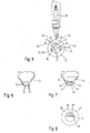
- Fig. 5 shows a schematic representation of a Abspritzabitess 31 of the fuel injection valve 25 of Fig. 4 in plan view and its orientation to the spark plug 20 schematically.
- fuel jets 29, 30, 31 of the three planes shown as arrows are sprayed off.
- two fuel jets 29 of the first plane are tangential to the spark plug 20 and oriented so that the spark plug 20 lies on an angle bisector of the fuel jets 29 of the first plane.
- a dotted line between the arrowheads illustrates the arrangement in one plane.
- Three second-level fuel jets 30 are staggered to the first-level fuel jets 29 so that the central fuel jet 29 a is oriented below the spark plug 20.
- Two third level fuel jets 30 are under the fuel jets. 28 aligned to the first level.
- Fig. 6 shows a schematic representation of the Abspritzabitess 31 of the fuel injection valve 25 of Fig. 4 seen in side view of the spark plug 20.
- the ejection openings 32 are distributed over a spherical surface 33 in three rows. The arrangement can be achieved by spraying in three levels.
- the fuel injection valve 25 are arranged laterally in the combustion chamber 19 and thus a high compatibility with conventional cylinder heads can be achieved.
- the remaining combustion chamber can be made relatively independent, since an ignitable mixture in the region of the spark plug 20 is formed by the fuel jets 29 of the first plane.
- the entire combustion chamber 19 including the region of the piston recess 26 can be achieved with fuel jets. It has been found that, contrary to the previous view, an injection of a fuel jet 28 from the side of the combustion chamber 19 to the spark plug 20 is possible.
- Fig. 7 shows a schematic representation of the Abspritzabitess 31 of the fuel injection valve 25 of Fig. 4 in an alternative favorable embodiment in side view of the spark plug 20 from.
- slots 34 are provided, can be generated by the flat jets.
- a web 35 prevents fuel is injected directly onto the spark plug 25.
- Fig. 8 shows a schematic representation of the Abspritzabitess 31 of the fuel injection valve 25 of Fig. 7 in supervision. Shown are the slots 34 and the web 35.
- the invention is not limited to the illustrated embodiments and z. B. applicable also for fuel injection systems with more or less injection holes, intake and exhaust valves and in particular a plurality of spark plugs and variable displacement volumes.
Landscapes
- Engineering & Computer Science (AREA)
- Chemical & Material Sciences (AREA)
- Combustion & Propulsion (AREA)
- Mechanical Engineering (AREA)
- General Engineering & Computer Science (AREA)
- Combustion Methods Of Internal-Combustion Engines (AREA)
- Fuel-Injection Apparatus (AREA)
Description
- Die Erfindung geht aus von einem Brennstoffeinspritzsystem nach der Gattung des Hauptanspruchs.
- Bei gemischverdichtenden, fremdgezündeten Brennkraftmaschinen mit innerer Gemischbildung ist für den Schichtladebetrieb im Zündkerzenbereich eine "Gemischwolke" erforderlich, die ein bestimmtes Brennstoff-Luftverhältnis im zündfähigen Bereich aufweist. Insbesondere im Teillastbetrieb und im Leerlauf sind dadurch erhebliche Verbrauchsvorteile zu erreichen, da nicht das gesamte Brennraumvolumen ein angereichertes zündfähiges Gemisch enthält.
- Um eine solche Gemischwolke zu erzeugen, sind im wesentlichen drei Verfahren bekannt. Das wandgeführte, das luftgeführte und das strahlgeführte Brennstoffeinspritzsystem.
- Beim wandgeführten Brennstoffeinspritzsystem wird der Brennstoff durch eine Luftwirbel mitgenommen, der sich an die Wand des Zylinders anlegt und zumeist an dem besonders ausgebildeten Kolben umgelenkt wird. Der Brennstoff wird dazu in einen Wirbel nahe der Wandfläche des Zylinders und/oder auf die Kolbenfläche durch ein Brennstoffeinspritzventil gespritzt, das seitlich des Einlaßventils zur Zylinderwand hin angeordnet ist. Durch den Wirbel wird der Brennstoff unter gleichzeitiger Gemischbildung zur zentral im Brennraum angeordneten Zündkerze getragen.
- Ein wandgeführtes Brennstoffeinspritzsystem ist beispielsweise aus der
EP 0 519 275 B1 bekannt. Eine Zündkerze ist in einem Mittelabschnitt einer inneren Wand eines Zylinderkopfes angeordnet und eine Brennstoffeinspritzeinrichtung ist an einem Umfangsabschnitt der inneren Wand des Zylinderkopfes angeordnet. Ein Kolben weist einen unter der Zündkerze befindlichen Vertiefungsabschnitt auf, auf dessen Fläche der Brennstoff schräg eingespritzt wird. Der Brennstoff wird am Rand der Vertiefungsfläche umgelenkt. Ein Wirbel trägt den Brennstoff weiter mit sich in Richtung Zündkerze. - Nachteilig an diesem Stand der Technik ist, daß die turbulenzerzeugenden Maßnahmen, wie besondere Ausbildungen der Brennraumgeometrie, insbesondere Ausbildungen der Kolbenform nur für einen bestimmten Drehzahlbereich optimiert werden könnten. Gerade im Bereich der Teillast und des Leerlaufs, d.h. gerade im Bereich der Teillast und des Leerlaufs, d. h. bei geringen Brennstoff-Einspritzmengen und Füllungsgraden und/oder niedrigen Drehzahlen können die nötigen Wirbelbildungen nur mit einer Drosselung erreicht werden. Dadurch kommt es jedoch zu einer Erhöhung des Brennstoffverbrauchs. Weiterhin ist nachteilig, daß beim wandgeführten Brennstoffeinspritzsystem eine aufwendigere Kolbenform mit einer Umlenkkante nötig ist.
- Aus der
DE 38 08 635 C2 ist eine Brennstoffeinspritzvorrichtung zum direkten Einspritzen von Brennstoff in den Zylinder einer gemischverdichtenden Brennkraftmaschine als ein luftgeführtes Brennnstoffeinspritzsystem bekannt. Die Brennstoffeinspritzvorrichtung umfaßt dabei ein Brennstoffeinspritzventil, das in der Zylinderwand in einigem Abstand vom Zylinderkopf und gegenüber der Auslaßöffnung angeordnet ist und eine Ausgangsöffnung aufweist, wobei die Strahlachse des Brennstoffeinspritzventils auf den Bereich um die im Zylinderkopf angeordnete Zündkerze gerichtet ist. Das Brennstoffeinspritzventil weist dabei eine magnetbetätigte Ventilnadel mit schraubenförmigen Drallnuten zum Erzeugen einer Drallströmung des Brennstoffstrahls auf. Die Gesamtquerschnittsfläche der Drallnuten ist um mindestens die Hälfte kleiner als die Querschnittsfläche der Ausgangsöffnung, wobei das Brennstoffeinspritzventil oberhalb einer Spülöffnung angeordnet ist und mit seiner Strahlachse auf den in der Zylinderkopfmitte angeordneten Zündpunkt zeigt. Durch die Luftströmung wird der eingespritzte Brennstoff ohne die Wand des Zylinders zu berühren in Richtung der Zündkerze mitgenommen und zu dieser transportiert. - Der Gemischtransport zur Zündkerze gelingt auch bei luftgeführten Brennstoffeinspritzsystemen aus den bereits genannten Gründen im Leerlauf- und unteren Teillastbetrieb nur sehr unvollkommen, im mittleren Teillastbetrieb zum Teil nur mit unvertretbar geringen Serienstreuungen der verwendeten Hochdruckeinspritzventile bzw. der Strömungsführung durch das Saugrohr. Die mangelhafte Reproduzierbarkeit zeigt sich vor allem an überhöhten Emissionen von unverbrannten Kohlenwasserstoffen, verursacht durch einzelne Verbrennungsaussetzer.
- Aus der
DE 198 04 463 A1 ist ein strahlgeführtes Brennstoffeinspritzsystem ' für gemischverdichtende, fremdgezündete Brennkraftmaschinen bekannt, welches mit wenigstens einem Brennstoffeinspritzventil den Brennstoff in einen von einer Kolben-/Zylinder-Anordnung gebildeten Brennraum einspritzt und mit einer in den Brennraum ragenden Zündkerze versehen ist. Der Düsenkörper des Brennstoffeinspritzventils ist dabei in der Nähe der zentral im Brennraum gelegenen Zündkerze angeordnet und mit wenigstens einer Reihe über den Umfang des Düsenkörpers verteilt angeordneten Einspritzlöchern versehen. Durch eine gezielte Einspritzung von Brennstoff über die Einspritzlöcher wird ein strahlgeführtes Brennverfahren durch Bildung einer Gemischwolke realisiert, wobei wenigstens ein Strahl in Richtung auf die Zündkerze gerichtet ist. Weitere Strahlen sorgen dafür, daß eine wenigstens annähernd geschlossene bzw. zusammenhängende Gemischwolke gebildet wird. - Aus der
DE 196 42 653 C1 ist ein Verfahren zur Bildung eines zündfähigen Brennstoff-Luftgemisches bekannt. In den Zylindern von direkt einspritzenden Brennkraftmaschinen ist ein zündfähiges Brennstoff-Luftgemisch bildbar, indem in jeden von einem Kolben begrenzten Brennraum mittels eines Injektors bei Freigabe einer Düsenöffnung durch Abheben eines Ventilgliedes von einem die Düsenöffnung umfassenden Ventilsitz Brennstoff eingespritzt wird. Um unter allen Betriebsbedingungen der Brennkraftmaschine, insbesondere im Schichtladebetrieb, eine verbrauchs- und emissionsoptimierte innere Gemischbildung in jedem Betriebspunkt des gesamten Kennfeldes zu ermöglichen, ist vorgesehen, daß der Öffnungshub des Ventilgliedes und die Einspritzzeit variabel einstellbar sind. - Nachteilig an diesen strahlgeführten Brennstoffeinspritzsystemen ist, daß bisherige Zylinderköpfe mit einer zentral in der Zylinderachse im Zylinderkopf angeordneten Zündkerze nur mit erheblichen Veränderungen verwendet werden können, da der zusätzliche Einbauraum für das Brennstoffeinspritzventil in der Nähe der Zündkerze nachteilig eine Verlegung der zumeist zwei Einlaßventile erfordert.
- Eine Kompatibilität zu den bisherigen Fertigungswerkzeugen und Zylinderkopfformen ist zwar bei einer Anordnung des Brennstofffeinspritzventils an der Zylinderwand auf der Seite der Einlaßventile gegeben, jedoch treten dann die zuvor beschriebenen Nachteile der luftgeführten und der wandgeführten Brennstoffeinspritzsysteme auf.
- Die
US-A-5 170 758 offenbart eine luftverdichtende, ventilgesteuerte Brennkraftmaschine für selbstzündungsunwillige Kraftstoffe, mit einer Einspritzdüse zur direkten Einspritzung des Kraftstoffes in einen im Kolben vorgesehenen Brennraum und mit einer Zündkerze sowie mit Vorrichtungen, um der einströmenden Verbrennungsluft eine Drallbewegung zu erteilen. Um mit relativ einfachen Mitteln eine zuverlässige Zündung zu erreichen, ist die Zündkerze im Zentralbereich des Brennraums angeordnet und es wird weiterhin eine Einspritzdüse mit mehreren Spritzöffnungen verwendet. - Die
DE 198 04 463 A1 offenbart ein Kraftstoffeinspritzsystem für Ottomotoren mit einer Einspritzdüse, die Kraftstoff in einen von einer Kolben-/Zylinder-Konstruktion gebildeten Brennraum einspritzt, und mit einer in den Brennraum ragenden Zündkerze. Die Einspritzdüse ist mit wenigstens einer Reihe über den Umfang der Einspritzdüse verteilt angeordneten Einspritzlöchern versehen. Durch eine gezielte Einspritzung von Kraftstoff über die Einspritzlöcher wird ein strahlgeführtes Brennverfahren durch Bildung einer Gemischwolke realisiert mit wenigstens einem Strahl, der zur Zündung in Richtung auf die Zündkerze gerichtet ist und mit weiteren Strahlen, durch die ein wenigstens annähernd geschlossene Gemischwolke gebildet wird. - Die
US-A-5 735 240 offenbart einen Verbrennungsmotor, wobei eine Einspritzdüse in der Zylinderbohrung entweder auf der Einlass- oder auf der Auslassseite angeordnet ist. Die Einspritzdüse ist derartig angeordnet, dass sie sich unterhalb der Oberseite des Kopfes des Zylinders an einer Totpunktposition befindet und eine Ausnehmung ist in dem Kolbenkopf gebildet, um eine Einspritzung vorzusehen, sogar, wenn sich der Kolben dem oberen Totpunkt nähert. - Die
JP 05 214938 A JP 06 081656 A - Das erfindungsgemäße Brennstoffeinspritzsystem mit den kennzeichnenden Merkmalen des Hauptanspruchs hat demgegenüber den Vorteil, daß eine Anordnung des Brennstoffeinspritzventils an der Zylinderwand im Zylinderkopf auf der Seite der Einlaßventile möglich ist und der Zylinderkopf mit den bisherigen Zylinderköpfen für Saugrohreinspritzung in der Fertigung kompatibel ist und die Nachteile der wand- und luftgeführten Brennstoffeinspritzsysteme vermieden werden, da das erfindungsgemäße Brennstoffeinspritzsystem ein strahlgeführtes Brennstoffeinspritzsystem ist. Entgegen der vorgefaßten Meinung der Fachwelt hat sich gezeigt, daß auch aus der Position des Brennstoffeinspritzventils bei dem erfindungsgemäßen Brennstoffeinspritzsystem ein strahlgeführtes Erzeugen einer Gemischwolke im Teillastbetrieb möglich ist. Ein Brennstoffstrahl eines Mehrlochbrennstoffeinspritzventils kann genügend genau und exakt durch den halben Zylinderdurchmesser eingespritzt werden.
- Weiterhin ist vorteilhaft, daß die Gemischbildung zur Zündung unabhängig von einer Wirbelbildung ist und die Brennraumgeometrie, insbesondere die Form des Kolbens unabhängig und zur Optimierung weiterer Gesichtspunkte geeignet gewählt werden kann.
- Durch die in den Unteransprüchen aufgeführten Maßnahmen sind vorteilhafte Weiterbildungen des im Hauptanspruch angegebenen Brennstoffeinspritzsystems möglich.
- Insbesondere werden die Thermoschockbelastung und die Verrußung der Zündkerze durch das auf die Zündkerzenposition bezogene tangentiale Einspritzen von Brennstoff vermindert. Die Brennstoffstrahlen sind also nicht direkt auf die Zündkerze gerichtet.
- Von Vorteil ist außerdem, daß durch zwei Brennstoffeinspritzstrahlen und Anordnung der Zündkerze auf der Winkelhalbierenden zwischen diesen Brennstoffstrahlen bei geeigneter Wahl des Winkels ein günstiges Zündverhalten erreicht werden kann.
- Weitere Brennstoffstrahlen können günstig in den übrigen Brennraum ausgerichtet werden, der sich bildet, wenn der Kolben sich ungefähr in der Nähe des oberen Totpunktes befindet.
- Insbesondere können die Brennstoffstrahlen vorteilhaft in drei Ebenen aufgeteilt sein, die zueinander gleiche Winkel zwischen ungefähr 20° und 30° einnehmen. Dabei besteht die oberste Ebene, die dem Zylinderkopf am nächsten liegt, aus den beiden die Zündkerze flankierenden Brennstoffstrahlen, die zweite aus drei Brennstoffstrahlen, von denen der mittlere auf der in Richtung der Zylinderachse projezierten Winkelhalbierenden der Brennstoffstrahlen der ersten Ebene liegt und die unterste Ebene wiederum aus zwei Brennstoffstrahlen, die unter denen der ersten Ebene liegen.
- Bei dieser Ausbildung der Brennstoffstrahlen ist ein gute Ausbreitung der Flammfront nach der Zündung über die drei Ebenen hinweg möglich.
- Der Kolben kann mit einer Quetschkante und mit einer Kolbenmulde ausgebildet sein und die Form des Strahlbildes an diesen dadurch bestimmten Brennraum angepaßt sein.
- Die Brennstoffstrahlen können Flachstrahlen sein, die durch Schlitze als Abspritzöffnungen eingespritzt werden.
- In einer alternativen günstigen Ausführungsform sind die weiteren Brennstoffstrahlen mit den tangential zur Zündkerze ausgerichteten Brennstoffstrahlen zusammen in einer Ebene angeordnet und ist deren Anzahl gerade und in gleicher Anzahl beidseits der Zündkerze angeordnet.
- Diese Ausführungsform ermöglicht eine günstige Gemischbildung vor allem, wenn keine oder eine sehr flache Kolbenmulde vorliegt.
- Ausführungsbeispiele der Erfindung sind in den Zeichnungen vereinfacht dargestellt und in der nachfolgenden Beschreibung näher erläutert. Es zeigen:
- Fig. 1
- einen schematischen Schnitt durch ein Brennstoffeinspritzsystem gemäß dem Stand der Technik für ein wandgeführtes Brennverfahren,
- Fig. 2
- einen schematischen Schnitt durch ein Brennstoffeinspritzsystem gemäß dem Stand der Technik für ein luftgeführtes Brennverfahren,
- Fig. 3
- einen schematischen Schnitt durch ein Brennstoffeinspritzsystem gemäß dem Stand der Technik für ein strahlgeführtes Brennverfahren,
- Fig. 4
- einen schematischen Schnitt durch ein erstes Ausführungsbeispiel des erfindungsgemäßen Brennstoffeinspritzsystems,
- Fig. 5
- eine schematische Darstellung des Abspritzabschnitts des Brennstoffeinspritzventils der
Fig. 4 in Aufsicht und dessen Orientierung zu der Zündkerze, - Fig. 6
- eine schematische Darstellung des Abspritzabschnitts des Brennstoffeinspritzventils der
Fig. 4 in Seitenansicht, - Fig. 7
- eine schematische Darstellung des Abspritzabschnitts des Brennstoffeinspritzventils der
Fig. 4 in einer günstigen Ausführungsform in Seitenansicht und - Fig. 8
- eine schematische Darstellung des Abspritzabschnitts des Brennstoffeinspritzventils der
Fig. 7 in Aufsicht. - Die
Fig. 1, 2 und 3 zeigen schematisch den Grundaufbau der drei wichtigsten Brennstoffeinspritzsysteme nach dem Stand der Technik, um zunächst die jeweiligen Vorteile und Nachteile zu verdeutlichen und zur Erläuterung, inwieweit die Erfindung unter Vermeidung der Nachteile die Vorteile der Brennstoffeinspritzsysteme verknüpft. -
Fig. 1 zeigt einen schematischen Schnitt durch ein Brennstoffeinspritzsystem gemäß dem Stand der Technik für ein wandgeführtes Brennstoffeinspritzsystem. In einem ausschnittsweisen, schematisiert dargestellten Zylinder 1 ist ein Kolben 2 geführt. Ein Brennraum 3 wird durch einen dem Zylinder 1 aufliegenden Zylinderkopf 4 begrenzt. Eine Zündkerze 5 befindet sich in der Mitte des Zylinders 1 und seitlich sind ein Auslaßventil 6 sowie ein Einlaßventil 7 für den Gasaustausch angeordnet. Üblicherweise werden meist zwei Einlaßventile 7 und Auslaßventile 6 vorgesehen. Auf der Seite des Einlaßventils 7 zur Wand des Zylinders 1 hin ist im Zylinderkopf 4 ein Brennstoffeinspritzventil 8 angeordnet. Der Kolben 2 weist eine deutlich ausgeformte Kolbenmulde 9 auf und ungefähr in Kolbenmitte eine die Kolbenmulde 9 begrenzende Umlenkkante 10. - Der Brennstoff wird von dem Brennstoffeinspritzventil 8 in Richtung der Kolbenmulde 9 eingespritzt. Dies ist in der
Fig. 1 durch eine Brennstoffwolke 11 angedeutet. Dabei trifft der Brennstoff in den Wirbel aus Luft und auf die Kolbenmulde 9. Durch den Wirbel wird der Brennstoff zur Umlenkkante 10 getrieben und unter Bildung eines Gemisches weiter zur Zündkerze 5. Der Weg dieser Gemischwolke ist durch einen Pfeil verdeutlicht. -
Fig. 2 zeigt einen schematischen Schnitt durch ein Brennstoffeinspritzsystem gemäß dem Stand der Technik für ein luftgeführtes Brennstoffeinspritzsystem. Soweit der prinzipielle Aufbau mit den Teilen Zylinder 1, Kolben 2, Brennraum 3, Zylinderkopf 4, Zündkerze 5, Auslaßventil 6, Einlaßventil 7 und Brennstoffeinspritzventil 8 dem derFig. 1 entspricht, werden dieselben Bezugszeichen verwendet. Abweichend ist eine relativ flache Kolbenmulde 12 an dem Kolben 2 ausgeformt. - Der Brennstoff wird von dem Brennstoffeinspritzventil 8 in Richtung eines Wirbels im Brennraum 3 eingespritzt. Dies ist in der
Fig. 2 durch eine Brennstoffwolke 13 angedeutet. Durch den Wirbel wird der Brennstoff unter Bildung eines Gemisches weiter zur Zündkerze 5 getrieben, ohne eine Wandung zu berühren. Der Weg dieser Gemischwolke ist durch einen Pfeil verdeutlicht. - Wand- und luftgeführte Brennstoffeinspritzsysteme bieten den Vorteil einer günstigen Position des Brennstoffeinspritzventils 8, die eine hohe Ähnlichkeit des Zylinderkopfes 4 zu herkömmlichen Zylinderköpfen für die Saugrohreinspritzung und die Weiterverwendung von Fertigungseinrichtungen ermöglicht. Nachteilig ist die stets notwendige Ausbildung eines Wirbels, durch die eine Optimierung des Brennraums nach sonstigen Gesichtspunkten erschwert wird und der nur für bestimmte Drehzahlen und Lastzustände optimiert werden kann sowie zu Drosselverlusten führt.
-
Fig. 3 zeigt einen schematischen Schnitt durch ein Brennstoffeinspritzsystem gemäß dem Stand der Technik für ein strahlgeführtes Brennstoffeinspritzsystem. Soweit der prinzipielle Aufbau mit den Teilen Zylinder 1, Kolben 2, Brennraum 3, Zylinderkopf 4, Auslaßventil 6, und Einlaßventil 7 dem derFig. 1 entspricht, werden dieselben Bezugszeichen verwendet. Abweichend sind ein Brennstoffeinspritzventil 14 und eine Zündkerze 15 in der Mitte des Zylinders 1 im Brennraum 3 zentral angeordnet. - Eine Brennstoffwolke 15, die aus einzelnen Brennstoffstrahlen besteht, wird von dem Brennstoffeinspritzventil 14 in den Brennraum 3 eingespritzt. Dabei werden zumindest Teile der Brennstoffwolke 16 direkt in die Nähe der Zündkerze 14 gespritzt und erzeugen dort ein zündfähiges Gemisch.
- Ein strahlgeführtes Brennstoffeinspritzsystem bietet den Vorteil, den übrigen Brennraum 3 relativ frei gestalten zu können und daß keine Drosselungsverluste auftreten. Nachteilig ist die fertigungstechnisch und vom Einbauraum ungünstige Position des Brennstoffeinspritzventils 15.
-
Fig. 4 zeigt einen schematischen Schnitt durch ein erstes Ausführungsbeispiel des erfindungsgemäßen Brennstoffeinspritzsystems mit einem Kolben 16, der in einer Zylinderbohrung 17 geführt ist und mit einem Zylinderkopf 18 einen Brennraum 19 umgrenzt. Eine Zündkerze 20 ist in der Mitte der Zylinderbohrung 17 und seitlich sind ein Auslaßventil 21 mit Auslaßkanal 22 sowie ein Einlaßventil 23 mit Einlaßkanal 24 für den Gasaustausch angeordnet. Üblicherweise werden meist zwei Einlaßventile 23 und Auslaßventile 21 vorgesehen. Auf der Seite des Einlaßventils 23 zur Wand der Zylinderbohrung 17 hin ist im Zylinderkopf 18 ein Brennstoffeinspritzventil 25 angeordnet. Der Kolben 16 weist eine deutlich ausgeformte Kolbenmulde 26 auf und eine die Kolbenmulde 26 begrenzende Quetschkante 27. - Der Kolben 16 ist in einer Stellung in der Zylinderbohrung 17 dargestellt, die dem Zeitpunkt der Brennstoffeinspritzung durch das Brennstoffeinspritzventil 25 entspricht. Das Brennstoffeinspritzventils 25 weist Abspritzöffnungen auf, die so angeordnet sind, daß Brennstoffstrahlen 28 einer ersten Ebene in den Bereich der Zündkerze 20 spritzen. Brennstoffstrahlen 29 einer zweiten Ebene nehmen zu den Brennstoffstrahlen der ersten Ebene in Bezug auf die Ebenen einen Winkel γ1 ein. Brennstoffstrahlen 30 einer dritten Ebene, die zu den Brennstoffstrahlen der zweiten Ebene in Bezug auf die Ebenen einen Winkel γ2 einnehmen, füllen den Bereich der Kolbenmulde 26. Die Brennstoffstrahlen sind durch Pfeile angedeutet. Der Winkel γ1 ist gleich dem Winkel γ2.
-
Fig. 5 zeigt eine schematische Darstellung eines Abspritzabschnitts 31 des Brennstoffeinspritzventils 25 derFig. 4 in Aufsicht und dessen Orientierung zu der Zündkerze 20 schematisch. Aus Abspritzöffnungen 32 werden als Pfeile dargestellte Brennstoffstrahlen 29,30,31 der drei Ebenen abgespritzt. In der hier beschriebenen Ausführungsform sind zwei Brennstoffstrahlen 29 der ersten Ebene tangential zur Zündkerze 20 ausgerichtet und so orientiert, daß die Zündkerze 20 auf einer Winkelhalbierenden der Brennstoffstrahlen 29 der ersten Ebene liegt. Durch eine gepunktete Linie zwischen den Pfeilspitzen ist die Anordnung in einer Ebene verdeutlicht. Drei Brennstoffstrahlen 30 der zweiten Ebene sind zu den Brennstoffstrahlen 29 der ersten Ebene versetzt angeordnet, so daß der mittlere Brennstoffstrahl 29a unter der Zündkerze 20 orientiert ist. Zwei Brennstoffstrahlen 30 der dritten Ebene sind unter den Brennstoffstrahlen. 28 der ersten Ebene ausgerichtet. -
Fig. 6 zeigt eine schematische Darstellung des Abspritzabschnitts 31 des Brennstoffeinspritzventils 25 derFig. 4 in Seitenansicht von der Zündkerze 20 aus gesehen. Die Abspritzöffnungen 32 sind über eine Kugelfläche 33 in drei Reihen verteilt. Durch die Anordnung kann ein Abspritzen in drei Ebenen erreicht werden. - Vorteilhaft kann bei dem erfindungsgemäßen Brennstoffeinspritzsystem in der vorliegenden Ausführungsform das Brennstoffeinspritzventil 25 im Brennraum 19 seitlich angeordnet werden und somit eine hohe Kompatibilität zu herkömmlichen Zylinderköpfen erreicht werden. Der restliche Brennraum kann relativ unabhängig gestaltet werden, da durch die Brennstoffstrahlen 29 der ersten Ebene ein zündfähiges Gemisch im Bereich der' Zündkerze 20 gebildet wird. Insbesondere kann durch die vorliegende günstige Ausführungsform der gesamte Brennraum 19 einschließlich des Bereichs der Kolbenmulde 26 mit Brennstoffstrahlen erreicht werden. Es hat sich gezeigt, daß entgegen bisheriger Ansicht eine Einspritzung eines Brennstoffstrahls 28 von der Seite des Brennraums 19 zur Zündkerze 20 möglich ist.
-
Fig. 7 zeigt eine schematische Darstellung des Abspritzabschnitts 31 des Brennstoffeinspritzventils 25 derFig. 4 in einer alternativen günstigen Ausführungsform in Seitenansicht von der Zündkerze 20 aus. Anstatt Abspritzöffnungen sind hier Schlitze 34 vorgesehen, durch die Flachstrahlen erzeugt werden können. Durch einen Steg 35 wird verhindert, daß Brennstoff direkt auf die Zündkerze 25 gespritzt wird. -
Fig. 8 zeigt eine schematische Darstellung des Abspritzabschnitts 31 des Brennstoffeinspritzventils 25 derFig. 7 in Aufsicht. Dargestellt sind die Schlitze 34 und der Steg 35. - Die Erfindung ist nicht auf die dargestellten Ausführungsbeispiele beschränkt und z. B. auch für Brennstoffeinspritzsysteme mit mehr oder weniger Einspritzlöchern, Ein- und Auslaßventilen und insbesondere mehreren Zündkerzen und variablen Hubraumvolumina anwendbar.
Claims (17)
- Brennstoffeinspritzsystem für Brennkraftmaschinen mit mindestens einem Brennstoffeinspritzventil (25), das Brennstoff in einen Brennraum (19) einspritzt, der von einer Zylinderwandung (17) begrenzt ist, in der ein Kolben (16) geführt ist, und mit einer in den Brennraum (19) ragenden Zündkerze (20), wobei das Brennstoffeinspritzventil (25) in dem Brennraum (19) im Bereich eines Gaseinlassventils (23) zur Zylinderwand (17) hin angeordnet ist und mehrere Brennstoffstrahlen (28, 29, 30) erzeugt,
dadurch gekennzeichnet,
dass die Brennstoffstrahlen (28, 29, 30) in drei Ebenen unter einem Winkel γ1 zwischen erster und zweiter Ebene sowie einem Winkel γ2 zwischen der zweiten und einer dritten Ebene orientiert sind, wovon die erste, dem Zylinderkopf (18) am nächsten liegende Ebene durch die zwei Brennstoffstrahlen (28) gebildet wird, die in den Bereich der Zündkerze (20) spritzen. - Brennstoffeinspritzsystem nach Anspruch 1,
dadurch gekennzeichnet,
dass Abspritzöffnungen (32) des Brennstoffeinspritzventils (25) so verteilt sind, dass zumindest zwei Brennstoffstrahlen (28) in den Bereich der Zündkerze (20) unter einem vorgegebenen Öffnungswinkel in den Brennraum (19) eingespritzt werden. - Brennstoffeinspritzsystem nach Anspruch 2,
dadurch gekennzeichnet,
dass die Zündkerze (20) auf der Winkelhalbierenden des Öffnungswinkels angeordnet ist. - Brennstoffeinspritzsystem nach Anspruch 3,
dadurch gekennzeichnet,
dass der Öffnungswinkel abhängig von einem Abstand des Brennstoffeinspritzventils (25) zu der Zündkerze (20) so groß ist, dass beidseits einer Zündelektrode der Zündkerze (20) ein zündfähiges Gemisch entsteht. - Brennstoffeinspritzsystem nach Anspruch 4,
dadurch gekennzeichnet,
dass weitere Brennstoffstrahlen (29, 30) bei einer Kolbenposition im Wesentlichen nahe dem oberen Totpunkt gleichmäßig in den übrigen Brennraum(19) ausgerichtet sind. - Brennstoffeinspritzsystem nach Anspruch 1,
dadurch gekennzeichnet,
dass die zweite Ebene aus drei Brennstoffstrahlen (30) gebildet wird, die zu den Brennstoffstrahlen (28) oder ersten Ebene versetzt sind, und der mittlere Brennstoffstrahl (29a) unter der Winkelhalbierenden des Öffnungswinkels der Brennstoffstrahlen (29) der ersten Ebene liegt. - Brennstoffeinspritzsystem nach Anspruch 6,
dadurch gekennzeichnet,
dass die dritte Ebene aus zwei Brennstoffstrahlen (30) besteht, die unter den Brennstoffstrahlen (28) der ersten Ebene liegen. - Brennstoffeinspritzsystem nach einem der Ansprüche 1 bis 7,
dadurch gekennzeichnet,
dass der Winkel γ1 einen Wert zwischen 20 und 30 aufweist. - Brennstoffeinspritzsystem nach einem der Ansprüche 1 bis 8,
dadurch gekennzeichnet,
dass der Winkel γ2 einen Wert zwischen 20 und 30 aufweist. - Brennstoffeinspritzsystem nach einem der Ansprüche 1 bis 8,
dadurch gekennzeichnet,
dass der Winkel γ1 gleich dem Winkel γ2 ist. - Brennstoffeinspritzsystem, nach einem der Ansprüche 1 bis 10,
dadurch gekennzeichnet,
dass die Anzahl der Brennstoffstrahlen gerade ist und eine gleiche Anzahl zu jeder Seite der Zündkerze (20) ausgerichtet ist. - Brennstoffeinspritzsystem nach einem der Ansprüche 1 bis 11,
dadurch gekennzeichnet,
dass die Brennstoffstrahlen Flachstrahlen sind und durch längliche Abspritzöffnungen des Brennstoffeinspritzventils (25) gebildet werden. - Brennstoffeinspritzsystem nach Anspruch 12,
dadurch gekennzeichnet,
dass die Abspritzöffnungen Schlitze (34) sind. - Brennstoffeinspritzsystem, nach Anspruch 13,
dadurch gekennzeichnet,
dass die Schlitze durch Stege (35) unterteilt sind. - Brennstoffeinspritzsystem nach einem der Ansprüche 1 bis 14,
dadurch gekennzeichnet,
dass der Kolben(16) auf der dem Brennstoffeinspritzventil (25) in Bezug auf eine Zylindermittelachse gegenüberliegenden Seite eine Quetschkante (27) aufweist. - Brennstoffeinspritzsystem nach einem der Ansprüche 1 bis 15,
dadurch gekennzeichnet,
dass der Kolben (16) eine Kolbenmulde (26) aufweist. - Brennstoffeinspritzsystem nach Anspruch 16,
dadurch gekennzeichnet,
dass die Kolbenmulde (26) in ihrer Form der Form des Strahlbildes des Brennstoffeinspritzventils(25) angepasst ist und kein Brennstoffstrahl (28, 29, 30) die Kolbenoberfläche direkt trifft.
Applications Claiming Priority (3)
| Application Number | Priority Date | Filing Date | Title |
|---|---|---|---|
| DE10124750 | 2001-05-21 | ||
| DE10124750A DE10124750A1 (de) | 2001-05-21 | 2001-05-21 | Brennstoffeinspritzsystem |
| PCT/DE2002/001694 WO2002095201A1 (de) | 2001-05-21 | 2002-05-10 | Brennstoffeinspritzsystem |
Publications (2)
| Publication Number | Publication Date |
|---|---|
| EP1395739A1 EP1395739A1 (de) | 2004-03-10 |
| EP1395739B1 true EP1395739B1 (de) | 2008-02-27 |
Family
ID=7685604
Family Applications (1)
| Application Number | Title | Priority Date | Filing Date |
|---|---|---|---|
| EP02740336A Expired - Lifetime EP1395739B1 (de) | 2001-05-21 | 2002-05-10 | Brennstoffeinspritzsystem |
Country Status (6)
| Country | Link |
|---|---|
| US (1) | US6883491B2 (de) |
| EP (1) | EP1395739B1 (de) |
| JP (1) | JP4047177B2 (de) |
| KR (1) | KR20030023708A (de) |
| DE (2) | DE10124750A1 (de) |
| WO (1) | WO2002095201A1 (de) |
Families Citing this family (27)
| Publication number | Priority date | Publication date | Assignee | Title |
|---|---|---|---|---|
| JP3722285B2 (ja) * | 2002-02-28 | 2005-11-30 | ヤマハ発動機株式会社 | 筒内燃料噴射式内燃機関 |
| JP3912194B2 (ja) * | 2002-06-11 | 2007-05-09 | マツダ株式会社 | 火花点火式直噴エンジン |
| DE10236622A1 (de) * | 2002-08-09 | 2004-02-19 | Daimlerchrysler Ag | Kraftstoffinjektor |
| JP4120799B2 (ja) * | 2003-02-17 | 2008-07-16 | 三菱自動車工業株式会社 | 内燃機関の燃料噴射装置 |
| US7032566B2 (en) * | 2003-05-30 | 2006-04-25 | Caterpillar Inc. | Fuel injector nozzle for an internal combustion engine |
| DE102004002296B4 (de) * | 2004-01-16 | 2013-10-10 | Audi Ag | Kraftstoffeinspritzung und Verfahren zur Einspritzung von Kraftstoff |
| WO2006084085A1 (en) | 2005-02-04 | 2006-08-10 | Ismailov Murad M | Liquid spray system and nozzle with improved spray generation |
| JP2006258035A (ja) * | 2005-03-18 | 2006-09-28 | Denso Corp | 燃料噴射弁 |
| JP4529950B2 (ja) * | 2005-08-25 | 2010-08-25 | 株式会社デンソー | 燃料噴射弁 |
| JP4501832B2 (ja) * | 2005-09-29 | 2010-07-14 | マツダ株式会社 | 火花点火式直噴エンジン |
| JP4542018B2 (ja) * | 2005-10-12 | 2010-09-08 | 日立オートモティブシステムズ株式会社 | エンジンの燃料噴射制御方法、及び、それに用いられるインジェクタを有するエンジン |
| JP4277883B2 (ja) | 2006-07-28 | 2009-06-10 | トヨタ自動車株式会社 | 筒内噴射式火花点火内燃機関 |
| US7740002B2 (en) * | 2006-09-05 | 2010-06-22 | Gm Global Technology Operations, Inc. | Fuel injector |
| US7565893B2 (en) | 2007-09-10 | 2009-07-28 | Gm Global Technology Operations, Inc. | Spark ignited direct injection flow geometry for improved combustion |
| DE102007042964A1 (de) | 2007-09-10 | 2009-03-19 | Fresenius Medical Care Deutschland Gmbh | Vorrichtung und Verfahren zur Behandlung einer medizinischen Flüssigkeit und medizinische Kassette |
| WO2009067495A2 (en) * | 2007-11-19 | 2009-05-28 | Deyang Hou | Premix combustion methods, devices and engines using the same |
| DE102008036840B4 (de) * | 2008-08-07 | 2013-08-01 | Ford Global Technologies, Llc | Direkteinspritzende fremdgezündete Brennkraftmaschine mit Einspritzdüse |
| US8402940B2 (en) * | 2010-04-01 | 2013-03-26 | GM Global Technology Operations LLC | Engine having fuel injection induced combustion chamber mixing |
| US8960151B2 (en) * | 2011-04-06 | 2015-02-24 | GM Global Technology Operations LLC | HCCI fuel injectors for robust auto-ignition and flame propagation |
| MX2013011860A (es) * | 2011-04-12 | 2014-01-31 | Nissan Motor | Motor de combustion interna. |
| WO2012146378A2 (de) * | 2011-04-29 | 2012-11-01 | Volkswagen Aktiengesellschaft | Verfahren und vorrichtung zum einspritzen von kraftstoff in einen brennraum |
| US9410521B2 (en) * | 2013-07-19 | 2016-08-09 | Ford Global Technologies, Llc | Fuel injector spray pattern |
| RU2598120C2 (ru) * | 2014-12-29 | 2016-09-20 | Сергей Михайлович Шепёлкин | Способ организации рабочего процесса в двигателях внутреннего сгорания с камерами сгорания имеющими вытеснители |
| CN108368817B (zh) * | 2015-11-10 | 2020-05-26 | 日产自动车株式会社 | 内燃机的控制方法以及控制装置 |
| DE102016212951A1 (de) * | 2016-07-15 | 2018-02-01 | Ford Global Technologies, Llc | Direkteinspritzende fremdgezündete Brennkraftmaschine mit im Zylinderrohr angeordneter Einspritzvorrichtung und Verfahren zum Betreiben einer derartigen Brennkraftmaschine |
| JP6951224B2 (ja) * | 2017-12-08 | 2021-10-20 | 日立Astemo株式会社 | 燃料噴射弁 |
| US12416280B2 (en) * | 2022-11-02 | 2025-09-16 | RK IP Holdings, LLC | High-pressure fuel injection system |
Family Cites Families (17)
| Publication number | Priority date | Publication date | Assignee | Title |
|---|---|---|---|---|
| JPS62288314A (ja) * | 1986-06-05 | 1987-12-15 | Isuzu Motors Ltd | 直噴式内燃機関の燃焼室構造 |
| US4899699A (en) * | 1988-03-09 | 1990-02-13 | Chinese Petroleum Company | Low pressure injection system for injecting fuel directly into cylinder of gasoline engine |
| AT403615B (de) * | 1991-03-12 | 1998-04-27 | Avl Verbrennungskraft Messtech | Luftverdichtende, ventilgesteuerte brennkraftmaschine |
| US5259348A (en) * | 1991-06-20 | 1993-11-09 | Toyota Jidosha Kabushiki Kaisha | Direct injection type engine |
| DE4140760C1 (de) * | 1991-12-11 | 1993-05-27 | Robert Bosch Gmbh, 7000 Stuttgart, De | |
| JPH05214938A (ja) * | 1992-02-03 | 1993-08-24 | Nissan Motor Co Ltd | 直噴式火花点火機関 |
| JP3295975B2 (ja) | 1992-09-02 | 2002-06-24 | 日産自動車株式会社 | ガソリンエンジン |
| US5735240A (en) * | 1995-06-19 | 1998-04-07 | Yamaha Hatsudoki Kabushiki Kaisha | Direct injected engine |
| JPH09126095A (ja) * | 1995-10-31 | 1997-05-13 | Toyota Central Res & Dev Lab Inc | 燃料噴射弁 |
| DE19642653C5 (de) * | 1996-10-16 | 2008-02-21 | Daimler Ag | Verfahren zur Bildung eines zündfähigen Kraftstoff/Luft-Gemisches |
| JP3191732B2 (ja) * | 1997-08-04 | 2001-07-23 | トヨタ自動車株式会社 | 筒内噴射式火花点火内燃機関 |
| JP3932697B2 (ja) * | 1998-10-01 | 2007-06-20 | 株式会社日立製作所 | 筒内噴射型内燃機関の燃料噴射方法および、燃料噴射弁,内燃機関,燃焼方法 |
| DE19804463B4 (de) * | 1998-02-05 | 2006-06-14 | Daimlerchrysler Ag | Kraftstoffeinspritzsystem für Ottomotoren |
| DE10032330A1 (de) * | 2000-07-04 | 2002-01-17 | Bosch Gmbh Robert | Brennstoffeinspritzsystem |
| AT5133U1 (de) * | 2000-10-03 | 2002-03-25 | Avl List Gmbh | Verfahren zum betreiben einer mit selbstzündbarem kraftstoff betriebenen brennkraftmaschine |
| JP3812338B2 (ja) * | 2001-01-05 | 2006-08-23 | 日産自動車株式会社 | 筒内直接燃料噴射式火花点火エンジン |
| JP3912194B2 (ja) * | 2002-06-11 | 2007-05-09 | マツダ株式会社 | 火花点火式直噴エンジン |
-
2001
- 2001-05-21 DE DE10124750A patent/DE10124750A1/de not_active Withdrawn
-
2002
- 2002-05-10 WO PCT/DE2002/001694 patent/WO2002095201A1/de not_active Ceased
- 2002-05-10 DE DE50211785T patent/DE50211785D1/de not_active Expired - Lifetime
- 2002-05-10 KR KR10-2003-7000849A patent/KR20030023708A/ko not_active Withdrawn
- 2002-05-10 US US10/333,656 patent/US6883491B2/en not_active Expired - Fee Related
- 2002-05-10 JP JP2002591643A patent/JP4047177B2/ja not_active Expired - Fee Related
- 2002-05-10 EP EP02740336A patent/EP1395739B1/de not_active Expired - Lifetime
Also Published As
| Publication number | Publication date |
|---|---|
| KR20030023708A (ko) | 2003-03-19 |
| JP4047177B2 (ja) | 2008-02-13 |
| EP1395739A1 (de) | 2004-03-10 |
| JP2004519617A (ja) | 2004-07-02 |
| DE50211785D1 (de) | 2008-04-10 |
| WO2002095201A1 (de) | 2002-11-28 |
| DE10124750A1 (de) | 2002-11-28 |
| US6883491B2 (en) | 2005-04-26 |
| US20040020459A1 (en) | 2004-02-05 |
Similar Documents
| Publication | Publication Date | Title |
|---|---|---|
| DE10124750A1 (de) | Brennstoffeinspritzsystem | |
| DE69500126T2 (de) | Eine fremdgezündete Brennkraftmaschine mit direkter Kraftstoffeinspritzung | |
| DE3903842C2 (de) | Otto-Brennkraftmaschine mit direkter Kraftstoffeinspritzung | |
| DE102010030692B4 (de) | Glühkerzenanordnung in einem Dieselmotor | |
| EP1290339B1 (de) | Brennstoffeinspritzsystem | |
| DE19804161C2 (de) | Viertakt-Brennkraftmaschine | |
| EP1301702B1 (de) | Brennstoffeinspritzsystem | |
| EP1290321B1 (de) | Brennstoffeinspritzsystem | |
| DE19713029C2 (de) | Viertakt-Brennkraftmaschine mit Fremdzündung | |
| DE102017127050B4 (de) | Funkengezündete direkteinspritzmotor-verbrennungssysteme | |
| EP1319822B9 (de) | Brennkraftmaschine mit Direkteinspritzung | |
| EP1290322B1 (de) | Brennstoffeinspritzsystem | |
| EP1533491A1 (de) | Brennstoffeinspritzsystem | |
| EP1387952B1 (de) | Brennstoffeinspritzsystem | |
| DE3943816C2 (de) | Otto-Brennkraftmaschine mit direkter Kraftstoffeinspritzung | |
| DE19621635A1 (de) | Diesel-Brennkraftmaschine | |
| DE10261181A1 (de) | Brennkraftmaschine mit Selbstzündung | |
| EP1481159B1 (de) | Brennstoffeinspritzventil | |
| DE102017107947A1 (de) | Strahlbild eines Mehrloch-Einspritzventils für Einspritzdrücke über 300 bar bei Ottomotoren mit zentraler Injektorlage | |
| DE102007042419A1 (de) | Ottomotor für ein Kraftfahrzeug und Verfahren zum Betreiben eines Ottomotors | |
| WO2006048129A1 (de) | Brennkraftmaschine | |
| WO2006048128A1 (de) | Brennraum einer brennkraftmaschine mit direkteinspritzung | |
| WO2006079369A1 (de) | Brennraumgestaltung einer direkteinspritzenden brennkraftmaschine | |
| DE19728946A1 (de) | Zylinderkopf einer direkteinspritzenden Brennkraftmaschine | |
| DE10050687A1 (de) | Verfahren zum Betreiben eines Verbrennungsmotors und Vorrichtung hierfür |
Legal Events
| Date | Code | Title | Description |
|---|---|---|---|
| PUAI | Public reference made under article 153(3) epc to a published international application that has entered the european phase |
Free format text: ORIGINAL CODE: 0009012 |
|
| 17P | Request for examination filed |
Effective date: 20031222 |
|
| AK | Designated contracting states |
Kind code of ref document: A1 Designated state(s): AT BE CH CY DE DK ES FI FR GB GR IE IT LI LU MC NL PT SE TR |
|
| 17Q | First examination report despatched |
Effective date: 20061017 |
|
| 17Q | First examination report despatched |
Effective date: 20061017 |
|
| GRAP | Despatch of communication of intention to grant a patent |
Free format text: ORIGINAL CODE: EPIDOSNIGR1 |
|
| GRAS | Grant fee paid |
Free format text: ORIGINAL CODE: EPIDOSNIGR3 |
|
| GRAA | (expected) grant |
Free format text: ORIGINAL CODE: 0009210 |
|
| AK | Designated contracting states |
Kind code of ref document: B1 Designated state(s): DE FR GB IT |
|
| REG | Reference to a national code |
Ref country code: GB Ref legal event code: FG4D Free format text: NOT ENGLISH |
|
| REF | Corresponds to: |
Ref document number: 50211785 Country of ref document: DE Date of ref document: 20080410 Kind code of ref document: P |
|
| ET | Fr: translation filed | ||
| PLBE | No opposition filed within time limit |
Free format text: ORIGINAL CODE: 0009261 |
|
| STAA | Information on the status of an ep patent application or granted ep patent |
Free format text: STATUS: NO OPPOSITION FILED WITHIN TIME LIMIT |
|
| 26N | No opposition filed |
Effective date: 20081128 |
|
| PGFP | Annual fee paid to national office [announced via postgrant information from national office to epo] |
Ref country code: GB Payment date: 20140520 Year of fee payment: 13 |
|
| REG | Reference to a national code |
Ref country code: FR Ref legal event code: PLFP Year of fee payment: 14 |
|
| PGFP | Annual fee paid to national office [announced via postgrant information from national office to epo] |
Ref country code: IT Payment date: 20150519 Year of fee payment: 14 Ref country code: FR Payment date: 20150519 Year of fee payment: 14 |
|
| PGFP | Annual fee paid to national office [announced via postgrant information from national office to epo] |
Ref country code: DE Payment date: 20150723 Year of fee payment: 14 |
|
| GBPC | Gb: european patent ceased through non-payment of renewal fee |
Effective date: 20150510 |
|
| PG25 | Lapsed in a contracting state [announced via postgrant information from national office to epo] |
Ref country code: GB Free format text: LAPSE BECAUSE OF NON-PAYMENT OF DUE FEES Effective date: 20150510 |
|
| REG | Reference to a national code |
Ref country code: DE Ref legal event code: R119 Ref document number: 50211785 Country of ref document: DE |
|
| PG25 | Lapsed in a contracting state [announced via postgrant information from national office to epo] |
Ref country code: IT Free format text: LAPSE BECAUSE OF NON-PAYMENT OF DUE FEES Effective date: 20160510 |
|
| REG | Reference to a national code |
Ref country code: FR Ref legal event code: ST Effective date: 20170131 |
|
| PG25 | Lapsed in a contracting state [announced via postgrant information from national office to epo] |
Ref country code: FR Free format text: LAPSE BECAUSE OF NON-PAYMENT OF DUE FEES Effective date: 20160531 Ref country code: DE Free format text: LAPSE BECAUSE OF NON-PAYMENT OF DUE FEES Effective date: 20161201 |