EP1301702B1 - Brennstoffeinspritzsystem - Google Patents
Brennstoffeinspritzsystem Download PDFInfo
- Publication number
- EP1301702B1 EP1301702B1 EP01953821A EP01953821A EP1301702B1 EP 1301702 B1 EP1301702 B1 EP 1301702B1 EP 01953821 A EP01953821 A EP 01953821A EP 01953821 A EP01953821 A EP 01953821A EP 1301702 B1 EP1301702 B1 EP 1301702B1
- Authority
- EP
- European Patent Office
- Prior art keywords
- injection
- injection holes
- fuel
- row
- holes
- Prior art date
- Legal status (The legal status is an assumption and is not a legal conclusion. Google has not performed a legal analysis and makes no representation as to the accuracy of the status listed.)
- Expired - Lifetime
Links
Images


Classifications
-
- F—MECHANICAL ENGINEERING; LIGHTING; HEATING; WEAPONS; BLASTING
- F02—COMBUSTION ENGINES; HOT-GAS OR COMBUSTION-PRODUCT ENGINE PLANTS
- F02M—SUPPLYING COMBUSTION ENGINES IN GENERAL WITH COMBUSTIBLE MIXTURES OR CONSTITUENTS THEREOF
- F02M61/00—Fuel-injectors not provided for in groups F02M39/00 - F02M57/00 or F02M67/00
- F02M61/16—Details not provided for in, or of interest apart from, the apparatus of groups F02M61/02 - F02M61/14
- F02M61/18—Injection nozzles, e.g. having valve seats; Details of valve member seated ends, not otherwise provided for
- F02M61/1806—Injection nozzles, e.g. having valve seats; Details of valve member seated ends, not otherwise provided for characterised by the arrangement of discharge orifices, e.g. orientation or size
- F02M61/182—Discharge orifices being situated in different transversal planes with respect to valve member direction of movement
-
- F—MECHANICAL ENGINEERING; LIGHTING; HEATING; WEAPONS; BLASTING
- F02—COMBUSTION ENGINES; HOT-GAS OR COMBUSTION-PRODUCT ENGINE PLANTS
- F02B—INTERNAL-COMBUSTION PISTON ENGINES; COMBUSTION ENGINES IN GENERAL
- F02B23/00—Other engines characterised by special shape or construction of combustion chambers to improve operation
- F02B23/08—Other engines characterised by special shape or construction of combustion chambers to improve operation with positive ignition
- F02B23/10—Other engines characterised by special shape or construction of combustion chambers to improve operation with positive ignition with separate admission of air and fuel into cylinder
- F02B23/104—Other engines characterised by special shape or construction of combustion chambers to improve operation with positive ignition with separate admission of air and fuel into cylinder the injector being placed on a side position of the cylinder
-
- F—MECHANICAL ENGINEERING; LIGHTING; HEATING; WEAPONS; BLASTING
- F02—COMBUSTION ENGINES; HOT-GAS OR COMBUSTION-PRODUCT ENGINE PLANTS
- F02M—SUPPLYING COMBUSTION ENGINES IN GENERAL WITH COMBUSTIBLE MIXTURES OR CONSTITUENTS THEREOF
- F02M61/00—Fuel-injectors not provided for in groups F02M39/00 - F02M57/00 or F02M67/00
- F02M61/16—Details not provided for in, or of interest apart from, the apparatus of groups F02M61/02 - F02M61/14
- F02M61/18—Injection nozzles, e.g. having valve seats; Details of valve member seated ends, not otherwise provided for
- F02M61/1806—Injection nozzles, e.g. having valve seats; Details of valve member seated ends, not otherwise provided for characterised by the arrangement of discharge orifices, e.g. orientation or size
- F02M61/1826—Discharge orifices having different sizes
-
- F—MECHANICAL ENGINEERING; LIGHTING; HEATING; WEAPONS; BLASTING
- F02—COMBUSTION ENGINES; HOT-GAS OR COMBUSTION-PRODUCT ENGINE PLANTS
- F02B—INTERNAL-COMBUSTION PISTON ENGINES; COMBUSTION ENGINES IN GENERAL
- F02B23/00—Other engines characterised by special shape or construction of combustion chambers to improve operation
- F02B23/08—Other engines characterised by special shape or construction of combustion chambers to improve operation with positive ignition
- F02B23/10—Other engines characterised by special shape or construction of combustion chambers to improve operation with positive ignition with separate admission of air and fuel into cylinder
- F02B2023/103—Other engines characterised by special shape or construction of combustion chambers to improve operation with positive ignition with separate admission of air and fuel into cylinder the injector having a multi-hole nozzle for generating multiple sprays
-
- F—MECHANICAL ENGINEERING; LIGHTING; HEATING; WEAPONS; BLASTING
- F02—COMBUSTION ENGINES; HOT-GAS OR COMBUSTION-PRODUCT ENGINE PLANTS
- F02B—INTERNAL-COMBUSTION PISTON ENGINES; COMBUSTION ENGINES IN GENERAL
- F02B75/00—Other engines
- F02B75/12—Other methods of operation
- F02B2075/125—Direct injection in the combustion chamber for spark ignition engines, i.e. not in pre-combustion chamber
-
- F—MECHANICAL ENGINEERING; LIGHTING; HEATING; WEAPONS; BLASTING
- F02—COMBUSTION ENGINES; HOT-GAS OR COMBUSTION-PRODUCT ENGINE PLANTS
- F02F—CYLINDERS, PISTONS OR CASINGS, FOR COMBUSTION ENGINES; ARRANGEMENTS OF SEALINGS IN COMBUSTION ENGINES
- F02F1/00—Cylinders; Cylinder heads
- F02F1/24—Cylinder heads
- F02F2001/244—Arrangement of valve stems in cylinder heads
- F02F2001/245—Arrangement of valve stems in cylinder heads the valve stems being orientated at an angle with the cylinder axis
-
- Y—GENERAL TAGGING OF NEW TECHNOLOGICAL DEVELOPMENTS; GENERAL TAGGING OF CROSS-SECTIONAL TECHNOLOGIES SPANNING OVER SEVERAL SECTIONS OF THE IPC; TECHNICAL SUBJECTS COVERED BY FORMER USPC CROSS-REFERENCE ART COLLECTIONS [XRACs] AND DIGESTS
- Y02—TECHNOLOGIES OR APPLICATIONS FOR MITIGATION OR ADAPTATION AGAINST CLIMATE CHANGE
- Y02T—CLIMATE CHANGE MITIGATION TECHNOLOGIES RELATED TO TRANSPORTATION
- Y02T10/00—Road transport of goods or passengers
- Y02T10/10—Internal combustion engine [ICE] based vehicles
- Y02T10/12—Improving ICE efficiencies
Definitions
- the invention is based on a fuel injection system according to the genus of the main claim.
- DE 198 27 219 A1 describes a fuel injection system known for an internal combustion engine, which has an injector with a fuel jet adjustment plate, which has first nozzle holes that run along a first circle are arranged, and second nozzle holes that run along a second circle are arranged.
- the second circle has one Diameter larger than that of the first circle is.
- the circles are coaxial to a central axis of the Adjustment plate arranged.
- Each hole axis of the second Nozzle holes form an acute angle with one Reference plane that is perpendicular to the central axis of the Valve body is. The angle is smaller than the one through each hole axis of the first nozzle holes with the Reference plane is formed.
- Atomizing fuel through the first nozzle holes be injected away from fuel atomization directed through the second nozzle holes be injected.
- they interfere Atomizing fuel through the first nozzle holes are injected, not the fuel atomizations that what it is injected through the second nozzle holes allows to inject fuel appropriately atomize.
- DE 198 04 463 A1 describes a fuel injection system for mixture-compressing, spark ignition internal combustion engines known, which with an injection valve, the fuel into one formed by a piston / cylinder arrangement Injected combustion chamber, and with one in the combustion chamber protruding spark plug is provided.
- the injection valve is with at least one row across the circumference of the injector distributed injection holes provided.
- the spark plug is usually molded directly. This leads to heavy sooting of the spark plug and frequent Thermal shocks, which makes the spark plug a shorter one Has lifespan.
- a disadvantage of the known from DE 196 42 653 C1 Process for the formation of an ignitable fuel / air mixture is also the impossibility, especially in Stratified charge operation small amounts of fuel precisely to be measured since the times for opening and closing the Fuel injector is not controlled precisely enough can be.
- the fuel injection system according to the invention with the has characteristic features of the main claim on the other hand the advantage that the arrangement of at least one row of injection holes and one central injection hole a mixture cloud in the combustion chamber is formed, which is over a stoichiometric or slightly fat core (0.8 ⁇ ⁇ 1.1) and a lean shell (1.5 ⁇ ⁇ 2.5).
- the different one is particularly advantageous Diameter of the injection holes of the at least one row circumferentially arranged injection holes and the central Injection hole.
- hole diameter can be a more or less fat core of the injection cone be designed.
- the diameter of the central injection hole chosen larger than the diameter of the rest Injection holes it is also possible to use the conical Injection jet to an approximately parachute-like shape give, which on the one hand fills the combustion chamber better and the mixture cloud can be stoichiometric is distributed more favorably.
- a geometric arrangement of the is also advantageous Injection holes in the inner and outer rows that one injection hole each in the inner row two Allocates injection holes in the outer row.
- the number the injection holes per row are therefore twice as high as large as the number of injection holes in the next smaller row. This makes the homogeneity as well Design and stoichiometry of the mixture cloud depending on Realizable requirement.
- Fig. 1 shows a schematic section through a Embodiment of a fuel injection system according to the state of the art.
- the fuel injection system 1 has a combustion chamber 2, which is separated by a cylinder wall 3, a cylinder head 4 and a piston 5 is limited.
- in the Piston 5 has a combustion chamber trough 6.
- a spark plug 8 In one Ridge 7 of the combustion chamber 2 is a spark plug 8 with two Electrodes 15 z. B. centrally located.
- An inlet valve 9 and an outlet valve 10 are on ridge slopes 11 of the Combustion chamber 2 indicated.
- Fuel injector 12 injects a cone Mixture cloud 13 into the combustion chamber 2.
- the geometry of the Combustion chamber trough 6 and the shape of the mixture cloud 13 determine the path of the mixture cloud 13 in the area of Spark gap 14, which is between the electrodes 15 of the Spark plug 8 extends.
- the mixture cloud 13 is by the electrical spark ignited the spark plug 8.
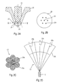
- FIGS. 2A-2D show a longitudinal and a cross section through a first embodiment of a valve body 20 of the Fuel injection valve 12 of an inventive Fuel injection system 1 and a longitudinal and one Cross section through the fuel injector 12 generated mixture cloud 13.
- FIG. 2A is a schematic longitudinal section through the spray-side part of the fuel injector 12 with a valve body 20 which with a valve closing body 21 cooperates, shown.
- the valve body 20 has a central injection hole 22 and a row 23 circumferentially arranged injection holes 24.
- FIG. 2B shows a section through the valve body 20 along the line marked II-II in FIG. 2A: In in the middle is the central injection hole 22.
- the circumferentially arranged injection holes 24 are uniform distributed over the circumference of the valve body 20. in the present embodiment were six Injection holes 24 selected.
- FIG. 2C shows an idealized cross section through the cone-shaped mixture cloud 13, which of the in Fig. 2A Fuel injector 12 shown is generated.
- Each of the injection holes 22 and 24 creates one cone-shaped injection jet 25.
- An inner Injection jet 25a is in this Embodiment six outer injection jets 25b surround.
- the resulting mixture cloud 13 in turn points an approximately conical envelope 26 and is relatively homogeneous (Fig. 2D). Slight overlaps of the inner injection jet 25a and the outer one Injection jets 25b lead to a slightly fat core Mixture cloud 13.
- FIG. 2D is a longitudinal section through the conical Mixture cloud 13, that of that shown in Fig. 2A Fuel injector 12 is generated shown.
- the arrow marked 0 represents the one through the central one Injection hole 22 generated internal injection jet 25a, while the arrows labeled 1 through the circumferentially arranged injection holes 24 produced outer Represent injection jets 25b.
- the envelope 26 of the outer injection jets 25b spreads approximately conical.
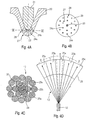
- 3A-3D are the spray-side on analogy to FIGS. 2A-2D Part of a second embodiment of the Fuel injector 12 in one longitudinal and one Cross section shown as well as the generated Mixture cloud 13 in a longitudinal and a cross section.
- FIG. 3A the spray-side part of the Fuel injection valve 12 with the valve closing body 21 and the valve body 20 shown.
- the valve body 20 points in the present second embodiment in addition to central injection hole 22 an inner row 27 circumferentially arranged injection holes 24a, and an outer row 28 circumferentially arranged injection holes 24b.
- At Actuation of the fuel injector 12 lifts the Valve closing body 21 from the valve body 20 and gives the Injection holes 22 and 24a and 24b free.
- FIG. 3B shows a cross section through the valve body 20 along the line labeled III-III in FIG. 3A.
- injection holes 24a the inner row 27 and injection holes 24b of the outer Row 28 arranged.
- FIG. 3C shows a cross section through the mixture cloud 13, which is represented by that shown in Fig. 3A
- Fuel injector 12 is generated.
- One through that central injection hole 22 generated central Injection jet 25a is the one of the injection jets 25b inner row 27 of circumferentially arranged injection holes 24a surrounded, which in turn by external injection jets 25c surrounded by injection holes 24b of the outer row 28 are injected.
- By slight overlaps of the Injection jets 25b with the central injection jet 25a a fat core area 29 is generated, which of a lean jacket area 30 is surrounded.
- 3D is a longitudinal section through that of FIG. 3A shown fuel injector 12 generated Mixture cloud 13 shown.
- the one marked with 0 Injection jet 25a is passed through the central injection hole 22 generated.
- the injection jets 25b labeled 1 through the injection holes 24a of the inner row 27 and the injection jets 25c marked with 2 become through the injection holes 24b of the outer row 28 injected.
- the envelope 26 of the mixture cloud 13 spreads turn almost conical.
- FIGS. 2A-2D and 3A-3D show in an analogous manner to FIGS. 2A-2D and 3A-3D a fuel injector 12, the Valve body 20 a central enlarged compared to FIG. 3A Injection hole 22 and an inner row 27 and an outer Row 28 of circumferentially arranged injection holes 24a and 24b includes.
- the valve closing body 21 lifts off from the valve body 20 and releases the injection holes 22 and 24a and 24b.
- FIG. 4B again shows the arrangement of the injection holes 22 and FIG. 24 in a sectional view along that with IV-IV marked line.
- the central injection hole 22 has a larger diameter than that on the inside Row 27 arranged injection holes 24a and those on the outer row 28 arranged injection holes 24b.
- Fig. 4C shows that by the compared to the previous Embodiments enlarged central injection hole 22nd evoked inner injection jet 25a with a cone larger diameter.
- the overlap areas of the inner injection jet 25a with the injection jets 25b of the inner row 27 thereby become larger, the fat one
- the core region 29 of the mixture cloud 13 thus becomes even richer.
- the fat core area 29 of the mixture cloud 13 is again surrounded by a lean jacket area 30.
- FIG. 4D is again a longitudinal section through the Mixture cloud 13 shown, which of the in Fig. 4A Fuel injector 12 shown in the combustion chamber 2 is injected.
- the inner injection jet 25a which through the enlarged central injection hole 22 evokes a larger space than for example the central one shown in FIG. 3D Injection jet 25a of the smaller sized central Injection hole 22.
- the smaller cone diameter is for Comparison with dashed lines in Fig. 4D characterized. With this arrangement, the fat one Core area 29 richer or leaner in any way designed and expanded as desired.
- the in the 3 and 4 illustrated embodiments have the inner row 27 six injection holes 24a and the outer Row 28 has twelve injection holes 24b.
- FIG. 5 A particularly advantageous arrangement of the injection holes 24 is shown in Fig. 5.
- the figure below shows a cross section through the spray end of Valve body 20 of fuel injector 12, for example along the section line III-III in Fig. 3A.
- the number of injection holes is special here 24a of the inner row 27 and the injection holes 24b of the outer row 28 linked together.
- the injection holes 24b the outer row 28 are arranged so that they are symmetrical to a half line 31, each from the central injection hole 22 through the holes 24a inner row 27 toward outer row 28 is aligned.
- the outer injection holes 24b are each arranged symmetrically to this half line 31.
- the number of injection holes is 24 in each further outer row 32 always twice as large as that Number of injection holes 24 in the adjacent inner one Line. In this way, a very homogeneous mixture cloud 13 are generated.
- FIG. 6 shows the general relationship between the diameter of the injection holes 24, the central injection hole 22 and the different injection angles ⁇ i and ⁇ a of the spray-side part of the valve body 20 of the fuel injection valve 12.
- the table below illustrates in general terms the optimal design of a fuel injection system 1 with a central injection hole 22 and at least two rows 27 and 28 of circumferentially arranged injection holes 24a and 24b.
- the table shows the number n z , n i , n a of the injection holes 24a and 24b, the hole diameter of the injection holes 22, 24a and 24b and the angle of inclination ⁇ i and ⁇ a, respectively the axes of the injection holes 22, 24a and 24b and the axes of the injection jets 25a, 25b and 25c relative to a central valve axis 33.
- each arrangement of injection holes 22, 24a and 24b in rows 27 and 28 can be described by a triple (n, ⁇ , ⁇ ), where n denotes the number of injection holes 24a, 24b per row 27 and 28, ⁇ the diameter of the injection holes 22, 24a and 24b and ⁇ the angle of inclination to the valve axis 33.
- the diameter of the central injection hole 22 should always be larger than the diameter of the injection holes 24a of the inner row 27, and this in turn should be larger than the diameter of the injection holes 24b of the outer row 28 ( ⁇ z > ⁇ i > ⁇ a ).
- the diameter of further rows of circumferentially arranged injection holes 24 become smaller and smaller as the number of rows increases.
- any Designs of the fuel injection system to match the Requirements for the internal combustion engine and the Combustion chamber geometry can be designed.
- the invention is not shown on the Embodiments limited and z. B. also for Fuel injectors with more than two rows of Injection holes, other injection hole diameters or a different number of injection holes per row applicable.
Description
- Fig. 1
- einen schematischen Schnitt durch ein Ausführungsbeispiel eines Brennstoffeinspritzsystems gemäß dem Stand der Technik,
- Fig. 2A-D
- einen Längs- und einen Querschnitt durch ein erstes Ausführungsbeispiel des Ventilkörpers des Brennstoffeinspritzventils eines erfindungsgemäßen Brennstoffeinspritzsystems sowie einen Längs- und einen Querschnitt durch die dadurch erzeugte Gemischwolke,
- Fig. 3A-D
- einen Längs- und einen Querschnitt durch ein zweites Ausführungsbeispiel des Ventilkörpers des Brennstoffeinspritzventils eines erfindungsgemäßen Brennstoffeinspritzsystems sowie einen Längs- und einen Querschnitt durch die dadurch erzeugte Gemischwolke,
- Fig. 4A-D
- einen Längs- und einen Querschnitt durch ein drittes Ausführungsbeispiel des Ventilkörpers des Brennstoffeinspritzventils eines erfindungsgemäßen Brennstoffeinspritzsystems sowie einen Längs- und einen Querschnitt durch die dadurch erzeugte Gemischwolke,
- Fig. 5
- einen Querschnitt durch das abspritzseitige Ende des Ventilkörpers des Brennstoffeinspritzventils eines erfindungsgemäßen Brennstoffeinspritzsystems,
- Fig. 6
- einen Längsschnitt durch ein weiteres Ausführungsbeispiel eines Ventilkörpers des Brennstoffeinspritzventils eines erfindungsgemäßen Brennstoffeinspritzsystems und
- Fig. 7
- die durch ein weiteres Ausführungsbeispiel des erfindungsgemäßen Brennstoffeinspritzsystems erzeugte Gemischwolke.
| Anzahl n der Löcher | Lochdürchmesser Φ | Neigungswinkel γ | |
| zentral angeordnetes Einspritzloch | 0<nz<1 | 50µm<Φz<200µm | 0° |
| innere Reihe Einspritzlöcher | 2<ni<7 | 40µm<Φi<180µm | 13°<γi<27° |
| äußere Reihe Einspritzlöcher | 5<na<14 | 30µm<Φa<160µm | 22°<γa<48° |
Claims (9)
- Brennstoffeinspritzsystem (1) für Brennkraftmaschinen mit einem Brennstoffeinspritzventil (12), das Brennstoff direkt in einen Brennraum (2) einspritzt, der von einer Zylinderwandung (3) gebildet wird, in der ein Kolben (5) geführt ist, und mit einer in den Brennraum (2) ragenden Zündkerze (8), wobei das Brennstoffeinspritzventil (12) in dem Brennraum (2) durch mindestens eine Reihe (23) auf einem Ventilkörper (20) des Brennstoffeinspritzventils (12) umfänglich angeordneter Einspritzlöcher (24) einen kegelförmigen Einspritzstrahl (13) erzeugt,
dadurch gekennzeichnet, daß der ventilkörper (20) , zusätzlich ein zentral angeordnetes Einspritzloch (22) aufweist, das einen zur Zündkerze (8) gelangenden, mit Brennstoff angereicherten Zentralbereich des Einspritzstrahls (13) erzeugt. - Brennstoffeinspritzsystem nach Anspruch 1,
dadurch gekennzeichnet, daß zwei Reihen (27, 28) von Einspritzlöchern (24a, 24b) vorgesehen sind. - Brennstoffeinspritzsystem nach Anspruch 1,
dadurch gekennzeichnet, daß der Durchmesser der Einspritzlöcher (24; 24a, 24b) der mindestens einen Reihe (23; 27, 28) und des zentralen Einspritzlochs (22) unterschiedlich sind. - Brennstoffeinspritzsystem nach einem der Ansprüche 1 bis 3,
dadurch gekennzeichnet, daß der Durchmesser des zentralen Einspritzlochs (22) größer ist als der Durchmesser der umfänglich auf der zumindest einen Reihe (23; 27, 28) angeordneten Einspritzlöcher (24; 24a, 24b). - Brennstoffeinspritzsystem nach Anspruch 4,
dadurch gekennzeichnet, daß zwei Reihen (27, 28) umfänglich angeordneter Einspritzlöcher (24a, 24b) vorgesehen sind und der Durchmesser der Einspritzlöcher (24a) in einer dem zentralen Einspritzloch (22) näherliegenden inneren Reihe (27) größer ist als der Durchmesser der Einspritzlöcher (24b) in einer äußeren Reihe (28). - Brennstoffeinspritzsystem nach Anspruch 5,
dadurch gekennzeichnet, daß der Durchmesser der Einspritzlöcher (24a, 24b) um so kleiner wird, je weiter diese vom zentralen Einspritzloch (22) entfernt sind. - Brennstoffeinspritzsystem nach Anspruch 5 oder 6,
dadurch gekennzeichnet, daß die Anzahl der Einspritzlöcher (24b) der äußeren Reihe (28) doppelt so groß ist wie die Anzahl der Einspritzlöcher (24a) der inneren Reihe (27). - Brennstoffeinspritzsystem nach Anspruch 7,
dadurch gekennzeichnet, daß jede weitere äußere Reihe (23) von umfänglich angeordneten Einspritzlöchern (24) doppelt so viele Einspritzlöcher (24) aufweist wie die nächst innere Reihe (23). - Brennstoffeinspritzsystem nach einem der Ansprüche 4 bis 8,
dadurch gekennzeichnet, daß die Einspritzlöcher (24a) der inneren Reihe (27) winkelversetzt zu den Einspritzlöchern (24b) der äußeren Reihe (28) angeordnet sind, wobei jeweils zwei Einspritzlöcher (24b) der äußeren Reihe (28) symmetrisch zu einer Halbgeraden (31) angeordnet sind, welche sich vom zentralen Einspritzloch (22) durch jedes der Einspritzlöcher (24a) der inneren Reihe (27) zur äußeren Reihe (28) erstreckt.
Applications Claiming Priority (3)
| Application Number | Priority Date | Filing Date | Title |
|---|---|---|---|
| DE10032336A DE10032336A1 (de) | 2000-07-04 | 2000-07-04 | Brennstoffeinspritzsystem |
| DE10032336 | 2000-07-04 | ||
| PCT/DE2001/002398 WO2002002928A1 (de) | 2000-07-04 | 2001-07-03 | Brennstoffeinspritzsystem |
Publications (2)
| Publication Number | Publication Date |
|---|---|
| EP1301702A1 EP1301702A1 (de) | 2003-04-16 |
| EP1301702B1 true EP1301702B1 (de) | 2004-10-06 |
Family
ID=7647648
Family Applications (1)
| Application Number | Title | Priority Date | Filing Date |
|---|---|---|---|
| EP01953821A Expired - Lifetime EP1301702B1 (de) | 2000-07-04 | 2001-07-03 | Brennstoffeinspritzsystem |
Country Status (6)
| Country | Link |
|---|---|
| US (1) | US6622693B2 (de) |
| EP (1) | EP1301702B1 (de) |
| JP (1) | JP2004502087A (de) |
| BR (1) | BR0106935A (de) |
| DE (2) | DE10032336A1 (de) |
| WO (1) | WO2002002928A1 (de) |
Families Citing this family (33)
| Publication number | Priority date | Publication date | Assignee | Title |
|---|---|---|---|---|
| JP3912194B2 (ja) * | 2002-06-11 | 2007-05-09 | マツダ株式会社 | 火花点火式直噴エンジン |
| JP4054223B2 (ja) * | 2002-06-12 | 2008-02-27 | 富士重工業株式会社 | 筒内噴射型エンジンおよび筒内噴射型エンジンの制御方法 |
| DE10236622A1 (de) * | 2002-08-09 | 2004-02-19 | Daimlerchrysler Ag | Kraftstoffinjektor |
| DK200201605A (da) * | 2002-10-22 | 2004-04-23 | Hans Jensen Lubricators As | Ventil til montering i cyllindervæg |
| JP2004225598A (ja) * | 2003-01-22 | 2004-08-12 | Hitachi Ltd | 燃料噴射弁 |
| US7032566B2 (en) | 2003-05-30 | 2006-04-25 | Caterpillar Inc. | Fuel injector nozzle for an internal combustion engine |
| DE10331267A1 (de) | 2003-07-10 | 2005-02-03 | Robert Bosch Gmbh | Brennstoffeinspritzsystem |
| DE102004002296B4 (de) * | 2004-01-16 | 2013-10-10 | Audi Ag | Kraftstoffeinspritzung und Verfahren zur Einspritzung von Kraftstoff |
| DE102004005727A1 (de) * | 2004-02-05 | 2005-09-01 | Robert Bosch Gmbh | Brennstoffeinspritzsystem |
| DE102004041031A1 (de) * | 2004-08-25 | 2006-03-02 | Audi Ag | Kraftstoff-Einspritzventil mit Strahldurchdringung |
| JP4508142B2 (ja) * | 2005-05-24 | 2010-07-21 | 株式会社デンソー | 内燃機関用燃料噴射弁 |
| JP4619989B2 (ja) * | 2005-07-04 | 2011-01-26 | 株式会社デンソー | 燃料噴射弁 |
| US7405281B2 (en) * | 2005-09-29 | 2008-07-29 | Pacific Biosciences Of California, Inc. | Fluorescent nucleotide analogs and uses therefor |
| JP4595924B2 (ja) * | 2006-02-09 | 2010-12-08 | 株式会社デンソー | 燃料噴射弁 |
| US7740002B2 (en) | 2006-09-05 | 2010-06-22 | Gm Global Technology Operations, Inc. | Fuel injector |
| DE102008003842A1 (de) | 2008-01-10 | 2009-07-16 | Robert Bosch Gmbh | Verfahren zum Verbrennen von Kraftstoff |
| JP5312148B2 (ja) * | 2009-03-30 | 2013-10-09 | 株式会社ケーヒン | 燃料噴射弁 |
| DE102009034072A1 (de) * | 2009-07-22 | 2011-01-27 | Emitec Gesellschaft Für Emissionstechnologie Mbh | Einspritzdüse zur Zufuhr von Reduktionsmittel und Vorrichtung zur Behandlung von Abgasen |
| US8960151B2 (en) * | 2011-04-06 | 2015-02-24 | GM Global Technology Operations LLC | HCCI fuel injectors for robust auto-ignition and flame propagation |
| EP2702256B1 (de) | 2011-04-29 | 2022-06-08 | Volkswagen Aktiengesellschaft | Verbrennungsmotor und verfahren zum einspritzen von kraftstoff in einen brennraum eines verbrennungsmotors |
| WO2013008692A1 (ja) * | 2011-07-11 | 2013-01-17 | ボッシュ株式会社 | 燃料噴射弁、内燃機関、及び燃料噴射方法 |
| US9181830B2 (en) | 2012-12-12 | 2015-11-10 | Caterpillar Inc. | After-treatment system and method for six-stroke combustion cycle |
| US8978603B2 (en) | 2012-12-12 | 2015-03-17 | Caterpillar Inc. | Six-stroke internal combustion engine valve activation system and method for operating such engine |
| US9133764B2 (en) | 2012-12-12 | 2015-09-15 | Caterpillar Inc. | Six-stroke engine system with blowdown exhaust recirculation |
| US8978602B2 (en) | 2012-12-12 | 2015-03-17 | Caterpillar Inc. | Six-stroke engine power density matching system and method |
| US9057324B2 (en) | 2012-12-12 | 2015-06-16 | Caterpillar Inc. | Six-stroke engine system with blowdown turbocharger |
| US8978601B2 (en) | 2012-12-12 | 2015-03-17 | Caterpillar Inc. | Six-stroke engine system with blowdown exhaust system |
| US9151222B2 (en) | 2012-12-12 | 2015-10-06 | Caterpillar Inc. | Six-stroke combustion cycle engine and process |
| US9957939B2 (en) | 2014-10-02 | 2018-05-01 | Cummins Inc. | Variable hole size nozzle and spray angle fuel injector and MHBIB |
| CN110023616B (zh) * | 2016-11-30 | 2021-11-09 | 日立安斯泰莫株式会社 | 燃料喷射装置 |
| DE102017107947A1 (de) | 2017-04-12 | 2018-10-18 | Volkswagen Ag | Strahlbild eines Mehrloch-Einspritzventils für Einspritzdrücke über 300 bar bei Ottomotoren mit zentraler Injektorlage |
| US11073071B2 (en) | 2019-07-23 | 2021-07-27 | Ford Global Technologies, Llc | Fuel injector with divided flowpath nozzle |
| WO2021059773A1 (ja) * | 2019-09-25 | 2021-04-01 | ボッシュ株式会社 | 燃料噴射弁及び燃料噴射弁を備える内燃機関 |
Family Cites Families (11)
| Publication number | Priority date | Publication date | Assignee | Title |
|---|---|---|---|---|
| US4548172A (en) * | 1983-06-22 | 1985-10-22 | Caterpillar Tractor Co. | Ignition-assisted fuel combustion system |
| US5058549A (en) * | 1988-02-26 | 1991-10-22 | Toyota Jidosha Kabushiki Kaisha | Fuel swirl generation type fuel injection valve and direct fuel injection type spark ignition internal combustion engine |
| US4932374A (en) * | 1989-06-21 | 1990-06-12 | General Motors Corporation | Fuel injector nozzle for internal combustion engine |
| JPH0763061A (ja) | 1993-08-24 | 1995-03-07 | Mazda Motor Corp | 直噴式火花点火エンジンの燃料噴射装置 |
| DE19642653C5 (de) | 1996-10-16 | 2008-02-21 | Daimler Ag | Verfahren zur Bildung eines zündfähigen Kraftstoff/Luft-Gemisches |
| US5713327A (en) * | 1997-01-03 | 1998-02-03 | Tilton; Charles L. | Liquid fuel injection device with pressure-swirl atomizers |
| JPH1172067A (ja) * | 1997-06-24 | 1999-03-16 | Toyota Motor Corp | 内燃機関の燃料噴射弁 |
| JP3191732B2 (ja) | 1997-08-04 | 2001-07-23 | トヨタ自動車株式会社 | 筒内噴射式火花点火内燃機関 |
| DE19804463B4 (de) * | 1998-02-05 | 2006-06-14 | Daimlerchrysler Ag | Kraftstoffeinspritzsystem für Ottomotoren |
| JP4122105B2 (ja) | 1999-03-01 | 2008-07-23 | 株式会社オプトニクス精密 | 噴射用ノズル |
| US6422198B1 (en) * | 2000-09-19 | 2002-07-23 | Delphi Technologies, Inc. | Pressure atomizer having multiple orifices and turbulent generation feature |
-
2000
- 2000-07-04 DE DE10032336A patent/DE10032336A1/de not_active Withdrawn
-
2001
- 2001-07-03 US US10/070,519 patent/US6622693B2/en not_active Expired - Fee Related
- 2001-07-03 DE DE50104014T patent/DE50104014D1/de not_active Expired - Lifetime
- 2001-07-03 WO PCT/DE2001/002398 patent/WO2002002928A1/de not_active Application Discontinuation
- 2001-07-03 JP JP2002507162A patent/JP2004502087A/ja active Pending
- 2001-07-03 BR BR0106935-7A patent/BR0106935A/pt active Search and Examination
- 2001-07-03 EP EP01953821A patent/EP1301702B1/de not_active Expired - Lifetime
Also Published As
| Publication number | Publication date |
|---|---|
| WO2002002928A1 (de) | 2002-01-10 |
| BR0106935A (pt) | 2002-05-14 |
| US6622693B2 (en) | 2003-09-23 |
| EP1301702A1 (de) | 2003-04-16 |
| DE50104014D1 (de) | 2004-11-11 |
| JP2004502087A (ja) | 2004-01-22 |
| DE10032336A1 (de) | 2002-01-17 |
| US20020185104A1 (en) | 2002-12-12 |
Similar Documents
| Publication | Publication Date | Title |
|---|---|---|
| EP1301702B1 (de) | Brennstoffeinspritzsystem | |
| DE3903842C2 (de) | Otto-Brennkraftmaschine mit direkter Kraftstoffeinspritzung | |
| EP1290339B1 (de) | Brennstoffeinspritzsystem | |
| EP1045136B1 (de) | Verfahren zum Betrieb einer Hubkolbenbrennkraftmaschine und Einspritzdüse zur Durchführung des Verfahrens | |
| DE3841142C2 (de) | Einspritzventil | |
| EP1387951B1 (de) | Brennstoffeinspritzsystem | |
| EP1395739B1 (de) | Brennstoffeinspritzsystem | |
| EP0975870B1 (de) | Brennstoffeinspritzventil oder brennstoffeinspritzdüse | |
| EP1290321B1 (de) | Brennstoffeinspritzsystem | |
| EP2652310B1 (de) | Kraftstoffeinspritzventil für brennkraftmaschinen | |
| EP1290322B1 (de) | Brennstoffeinspritzsystem | |
| EP1408231A1 (de) | Einspritzvorrichtung zum Einspritzen von Kraftstoff | |
| EP1387952B1 (de) | Brennstoffeinspritzsystem | |
| EP2898214B1 (de) | Kraftstoff-einspritzsystem einer brennkraftmaschine | |
| DE3943816C2 (de) | Otto-Brennkraftmaschine mit direkter Kraftstoffeinspritzung | |
| EP1481159B1 (de) | Brennstoffeinspritzventil | |
| DE10153629B4 (de) | Verfahren zum Einspritzen von Brennstoff | |
| WO2005008039A1 (de) | Brennstoffeinspritzsystem | |
| DE102018209097A1 (de) | Injektor und Brennkraftmaschine mit adaptivem Einspritzverhalten | |
| DE102005056764A1 (de) | Brennstoffeinspritzventil |
Legal Events
| Date | Code | Title | Description |
|---|---|---|---|
| PUAI | Public reference made under article 153(3) epc to a published international application that has entered the european phase |
Free format text: ORIGINAL CODE: 0009012 |
|
| 17P | Request for examination filed |
Effective date: 20030204 |
|
| AK | Designated contracting states |
Designated state(s): AT BE CH CY DE DK ES FI FR GB GR IE IT LI LU MC NL PT SE TR |
|
| 17Q | First examination report despatched |
Effective date: 20031007 |
|
| GRAP | Despatch of communication of intention to grant a patent |
Free format text: ORIGINAL CODE: EPIDOSNIGR1 |
|
| GRAS | Grant fee paid |
Free format text: ORIGINAL CODE: EPIDOSNIGR3 |
|
| GRAA | (expected) grant |
Free format text: ORIGINAL CODE: 0009210 |
|
| AK | Designated contracting states |
Kind code of ref document: B1 Designated state(s): DE FR GB IT |
|
| REG | Reference to a national code |
Ref country code: GB Ref legal event code: FG4D Free format text: NOT ENGLISH |
|
| REG | Reference to a national code |
Ref country code: IE Ref legal event code: FG4D Free format text: GERMAN |
|
| REF | Corresponds to: |
Ref document number: 50104014 Country of ref document: DE Date of ref document: 20041111 Kind code of ref document: P |
|
| GBT | Gb: translation of ep patent filed (gb section 77(6)(a)/1977) |
Effective date: 20050208 |
|
| REG | Reference to a national code |
Ref country code: IE Ref legal event code: FD4D |
|
| ET | Fr: translation filed | ||
| PLBE | No opposition filed within time limit |
Free format text: ORIGINAL CODE: 0009261 |
|
| STAA | Information on the status of an ep patent application or granted ep patent |
Free format text: STATUS: NO OPPOSITION FILED WITHIN TIME LIMIT |
|
| 26N | No opposition filed |
Effective date: 20050707 |
|
| PGFP | Annual fee paid to national office [announced via postgrant information from national office to epo] |
Ref country code: GB Payment date: 20070730 Year of fee payment: 7 |
|
| PGFP | Annual fee paid to national office [announced via postgrant information from national office to epo] |
Ref country code: IT Payment date: 20070727 Year of fee payment: 7 |
|
| PGFP | Annual fee paid to national office [announced via postgrant information from national office to epo] |
Ref country code: FR Payment date: 20070718 Year of fee payment: 7 |
|
| GBPC | Gb: european patent ceased through non-payment of renewal fee |
Effective date: 20080703 |
|
| REG | Reference to a national code |
Ref country code: FR Ref legal event code: ST Effective date: 20090331 |
|
| PG25 | Lapsed in a contracting state [announced via postgrant information from national office to epo] |
Ref country code: GB Free format text: LAPSE BECAUSE OF NON-PAYMENT OF DUE FEES Effective date: 20080703 |
|
| PG25 | Lapsed in a contracting state [announced via postgrant information from national office to epo] |
Ref country code: IT Free format text: LAPSE BECAUSE OF NON-PAYMENT OF DUE FEES Effective date: 20080703 Ref country code: FR Free format text: LAPSE BECAUSE OF NON-PAYMENT OF DUE FEES Effective date: 20080731 |
|
| PGFP | Annual fee paid to national office [announced via postgrant information from national office to epo] |
Ref country code: DE Payment date: 20150925 Year of fee payment: 15 |
|
| REG | Reference to a national code |
Ref country code: DE Ref legal event code: R119 Ref document number: 50104014 Country of ref document: DE |
|
| PG25 | Lapsed in a contracting state [announced via postgrant information from national office to epo] |
Ref country code: DE Free format text: LAPSE BECAUSE OF NON-PAYMENT OF DUE FEES Effective date: 20170201 |