EP1394417A2 - Rotary vane gas compressor - Google Patents
Rotary vane gas compressor Download PDFInfo
- Publication number
- EP1394417A2 EP1394417A2 EP03254211A EP03254211A EP1394417A2 EP 1394417 A2 EP1394417 A2 EP 1394417A2 EP 03254211 A EP03254211 A EP 03254211A EP 03254211 A EP03254211 A EP 03254211A EP 1394417 A2 EP1394417 A2 EP 1394417A2
- Authority
- EP
- European Patent Office
- Prior art keywords
- supplying passage
- pressure
- supplying
- passage
- gas compressor
- Prior art date
- Legal status (The legal status is an assumption and is not a legal conclusion. Google has not performed a legal analysis and makes no representation as to the accuracy of the status listed.)
- Granted
Links
Images



Classifications
-
- F—MECHANICAL ENGINEERING; LIGHTING; HEATING; WEAPONS; BLASTING
- F04—POSITIVE - DISPLACEMENT MACHINES FOR LIQUIDS; PUMPS FOR LIQUIDS OR ELASTIC FLUIDS
- F04C—ROTARY-PISTON, OR OSCILLATING-PISTON, POSITIVE-DISPLACEMENT MACHINES FOR LIQUIDS; ROTARY-PISTON, OR OSCILLATING-PISTON, POSITIVE-DISPLACEMENT PUMPS
- F04C28/00—Control of, monitoring of, or safety arrangements for, pumps or pumping installations specially adapted for elastic fluids
- F04C28/06—Control of, monitoring of, or safety arrangements for, pumps or pumping installations specially adapted for elastic fluids specially adapted for stopping, starting, idling or no-load operation
-
- F—MECHANICAL ENGINEERING; LIGHTING; HEATING; WEAPONS; BLASTING
- F01—MACHINES OR ENGINES IN GENERAL; ENGINE PLANTS IN GENERAL; STEAM ENGINES
- F01C—ROTARY-PISTON OR OSCILLATING-PISTON MACHINES OR ENGINES
- F01C21/00—Component parts, details or accessories not provided for in groups F01C1/00 - F01C20/00
- F01C21/08—Rotary pistons
- F01C21/0809—Construction of vanes or vane holders
- F01C21/0818—Vane tracking; control therefor
- F01C21/0854—Vane tracking; control therefor by fluid means
- F01C21/0872—Vane tracking; control therefor by fluid means the fluid being other than the working fluid
-
- F—MECHANICAL ENGINEERING; LIGHTING; HEATING; WEAPONS; BLASTING
- F04—POSITIVE - DISPLACEMENT MACHINES FOR LIQUIDS; PUMPS FOR LIQUIDS OR ELASTIC FLUIDS
- F04C—ROTARY-PISTON, OR OSCILLATING-PISTON, POSITIVE-DISPLACEMENT MACHINES FOR LIQUIDS; ROTARY-PISTON, OR OSCILLATING-PISTON, POSITIVE-DISPLACEMENT PUMPS
- F04C18/00—Rotary-piston pumps specially adapted for elastic fluids
- F04C18/30—Rotary-piston pumps specially adapted for elastic fluids having the characteristics covered by two or more of groups F04C18/02, F04C18/08, F04C18/22, F04C18/24, F04C18/48, or having the characteristics covered by one of these groups together with some other type of movement between co-operating members
- F04C18/34—Rotary-piston pumps specially adapted for elastic fluids having the characteristics covered by two or more of groups F04C18/02, F04C18/08, F04C18/22, F04C18/24, F04C18/48, or having the characteristics covered by one of these groups together with some other type of movement between co-operating members having the movement defined in group F04C18/08 or F04C18/22 and relative reciprocation between the co-operating members
- F04C18/344—Rotary-piston pumps specially adapted for elastic fluids having the characteristics covered by two or more of groups F04C18/02, F04C18/08, F04C18/22, F04C18/24, F04C18/48, or having the characteristics covered by one of these groups together with some other type of movement between co-operating members having the movement defined in group F04C18/08 or F04C18/22 and relative reciprocation between the co-operating members with vanes reciprocating with respect to the inner member
- F04C18/3446—Rotary-piston pumps specially adapted for elastic fluids having the characteristics covered by two or more of groups F04C18/02, F04C18/08, F04C18/22, F04C18/24, F04C18/48, or having the characteristics covered by one of these groups together with some other type of movement between co-operating members having the movement defined in group F04C18/08 or F04C18/22 and relative reciprocation between the co-operating members with vanes reciprocating with respect to the inner member the inner and outer member being in contact along more than one line or surface
Definitions
- the present invention relates to a vane rotary type gas compressor for use in an automotive air conditioning system or the like and, in particular, to a vane rotary type gas compressor improved in terms of vane projectability at the time of operation start of the compressor.
- Figs. 6 through 8 show a conventional vane rotary type gas compressor.
- refrigerant gas is introduced into a suction chamber 2 from the piping of an air conditioning system (not shown) through a suction port 2a.
- the refrigerant gas introduced into the suction chamber 2 is sucked into a cylinder chamber 5 in a cylinder 3 by the torque of a rotor 4 in the cylinder 3 and is compressed therein.
- the compressed refrigerant gas is discharged into an exhaust chamber 6, stored temporarily therein, and returned to the piping of the system from a discharge port 6a.
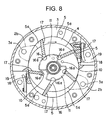
- the cylinder 3 with an elliptical inner peripheral surface is equipped with the rotor 4.
- a plurality of slit-like vane grooves 16 are radially formed in the outer peripheral surface of the rotor 4, and vanes 17 are fitted in the vane grooves 16 so as to be capable of radially projecting and retracting from and into the rotor 4.
- vanes 17 are capable of moving toward and away from the inner peripheral surface of the cylinder 3 by the centrifugal force due to the rotation of the rotor 4 and back pressure of vane groove bottom portions 16a, and divide the cylinder chamber 5 defined by the inner peripheral surface of the cylinder 3 and the outer peripheral surface of the rotor 4 into a plurality of compression chambers 5a.
- discharge chambers 19 and discharge valves in each discharge chambers there are provided discharge chambers 19 and discharge valves in each discharge chambers.
- cylinder discharge holes 18 establishing communication between the discharge chambers 19 and the cylinder chamber 5.
- suction passages 2b arranged in the front side of the cylinder chamber 5
- suction passages 3a establishing communication between the suction passages 2b and the rear side of the cylinder chamber 5.
- the compressor main body 1 is constructed as described above, and the compression chambers 5a defined by the vanes 17 repeatedly undergo changes in volume by rotation of the rotor 4.
- the refrigerant gas in the suction chamber 2 is sucked into the compression chambers 5a through the suction passages 2b and the cylinder suction passages 3a by the compression chambers 5a, which repeatedly undergo changes in volume.
- the sucked refrigerant gas is compressed by the compression chambers 5a.
- the refrigerant gas is discharged into the discharge chambers 19 through the cylinder discharge holes 18.
- the gas compressor sucks in and compresses refrigerant gas, so that it is necessary to effect lubrication and sealing on plain bearings and other sliding portions etc in the compressor main body 1 and on the sliding portions such as the rotor 4 and vanes 17 and the compression chambers 5a in the cylinder 3, and lubricant is used for that purpose.
- a supplying system for supplying lubricant for supplying lubricant.
- the lubricant supplying system in the compressor main body 1 and the cylinder 3 will be described.
- Lubricant is stored in an oil sump 7 formed in the lower portion of the exhaust chamber 6.
- the lubricant stored in the oil sump 7 is supplied to the various portions mentioned above. More specifically, lubricant is supplied to a plain bearing 9a in the rear side block 9 and a plain bearing 8a in the front side block 8.
- lubricant is supplied to flat grooves 11 formed in the rear side block 9 and the front side block 8 so as to be opposed to the rotor 4 and adapted to communicate with one of the plurality of vane grooves 16 when the rotating angle of the rotor 4 is within a fixed angle range. Further, lubricant is supplied to a high pressure supplying hole 10 formed in the rear side block 9 so as to be opposed to the rotor 4 and adapted to communicate with one of the plurality of vane grooves 16 when the rotating angle of the rotor 4 is within a fixed angle range. Further, lubricant is supplied to the compression chambers 5a and other sliding portions. At this time, the flat groove 11 and the high pressure supplying hole 10 are spaced apart from each other to a degree such that they do not communicate with each other through the vane grooves 16.
- Lubricant is supplied to the plain bearing 9a in the rear side block 9 through a first supply passage 12 formed in the rear side block 9 and establishing communication between the oil sump 7 and the plain bearing 9a.
- Lubricant is supplied to the plain bearing 8a in the front side block through a third supplying passage 13 formed in the rear side block 9, the cylinder 3, and the front side block 8 and establishing communication between the oil sump 7 and the plain bearing 8a. Due to the clearance between the rear side block 9 and the shaft, the lubricant supplied to the plain bearing 9a in the rear side block is supplied to the flat groove 11.
- Lubricant is supplied to the high pressure supplying hole 10 through the first supplying passage 12 formed in the rear side block 9 and establishing communication between the oil sump 7 and the high pressure supplying hole 10.
- the first supplying passage 12 is branched into the plain bearing 9a side and the high pressure supplying hole 10 side in the rear side block.
- the refrigerant gas compressed through the rotation of the rotor 4 is discharged into the exhaust chamber 6 to increase the pressure inside the exhaust chamber 6, with the result that pressure is applied to the surface of the oil sump 7, whereby lubricant is circulated through the supplying passages to effect lubrication or sealing on the sliding portions. Then, the lubricant is mixed into the refrigerant gas inside the cylinder 3, and discharged into the exhaust chamber 6 to return to the oil sump 7 again, thereby circulating through the compressor main body 1 again. See for example, Japanese Patent Publication Number JP 2002-227784 A.
- the rotor 4 is rotating at a high speed, and the pressure of the exhaust chamber 6 is higher than that in the suction chamber 2 due to the compressed refrigerant discharged into it, with lubricant in the oil sump 7 circulating through the gas compressor and the flat groove 11 also being filled with lubricant.
- the vanes 17 are pressed against the inner peripheral surface of the cylinder 3 by the centrifugal force due to the high-speed rotation of the rotor 4 and the vane back pressure due to the supply to the vane groove bottom portions 16a of the lubricant in the flat groove 11 communicating with the vane grooves 16 .
- the vanes 17 thus pressed divide the cylinder chamber 5, thereby defining the compression chambers 5a.
- the suction/compression process refers to the process from starting of an increase in the volume of the compression chambers 5a and starting of flowing-in of refrigerant gas into the compression chambers 5a to starting of a reduction in the volume of the compression chambers 5a, with refrigerant gas not having been discharged from the compression chambers 5a yet.
- the pressure inside the compression chambers 5a is increased by the pressure of the compressed refrigerant gas, and this pressure causes the vanes 17 to be pushed back toward the interior of the vane grooves 16 to be nearly separated from the inner peripheral surface of the cylinder 3.
- the high pressure supplying hole 10 is adapted to communicate with the vane grooves 16, and lubricant at a pressure equal to that in the exhaust chamber 6 is supplied from this high pressure supplying hole 10 to the vane groove bottom portions 16a to add to the vane back pressure. Due to this vane back pressure, the vanes 17 are prevented from being separated from the inner peripheral surface of the cylinder 3 as a result of being pushed back toward the interior of the vane grooves 16.
- the present invention has been made in view of the above problems. It is an object of the present invention to provide a gas compressor improved in terms of the projectability of the vanes 17 at the start of the compressor and of the compression performance at the start of the compressor.
- the present invention aims to improve the projectability of the vanes 17 at the start of the compressor.
- a deterioration in the projectability of the vanes 17 at the start of the compressor is caused by a shortage of centrifugal force applied to the vanes 17 due to low-speed rotation of the rotor 4, a reduction in the vane back pressure attributable to a shortage of lubricant supplied to the vane grooves 16 due to a shortage of lubricant supplied to the flat groove 11, etc. That is, the deterioration inprojectability is caused by deficiency in the force with which the vanes 17 are caused to project into the cylinder chamber 5 to be pressed against the inner peripheral wall of the cylinder 3.
- the high pressure supplying hole 10 is filled with lubricant supplied from the oil sump 7 through the first supplying passage 12.
- lubricant at a pressure equivalent to that of the exhaust chamber 6 is supplied to the vane groove bottom portions 16a to thereby provide vane back pressure, which prevents the vanes 17 from being pushed back into the vane grooves 16 to be separated from the inner peripheral surface of the cylinder 3 .
- high pressure refrigerant gas is discharged into the high pressure supplying hole 10 at the start of the compressor to fill the high pressure supplying hole 10 with high pressure refrigerant gas.
- the high pressure refrigerant gas existing in the high pressure supplying hole 10 is utilized in order to compensate for the deficiency in the force with which the vanes 17 are pressed against the inner peripheral surface of the cylinder 3 at the start of the compressor.
- the high pressure refrigerant gas existing in the high pressure supplying hole 10 is supplied to the vane groove bottom portions 16a during the suction/compression process effected by the rotation of the rotor 4, thereby obtaining a third force for causing the vanes 17 to project.
- a gas compressor for sucking in, compressing, and discharging refrigerant gas characterized by including: an elliptical cylinder, a rotor rotatably arranged in the cylinder, vane grooves radially formed in the rotor, vanes provided in the vane grooves and capable of projecting and retracting radially with respect to the rotor, a flat groove adapted to communicate with vane groove bottom portions during a refrigerant gas sucking/compressing process, a high pressure supplying hole adapted to communicate with the vane groove bottom portions upon interception of the communication between the vane groove bottom portions and the flat groove in the refrigerant gas compressing process, and a communication passage adapted to establish communication between the flat groove and the high pressure supplying hole at the start of operation of the gas compressor.
- the present invention which adopts the above construction, it is possible, at the start of the compressor, to discharge the high pressure refrigerant gas filling the high pressure supplying hole into the flat groove through the communication passage.
- the gas compressor is characterized by further including: a discharge chamber for temporarily storing refrigerant gas discharged from the cylinder, an oil sump formed in a lower portion of the exhaust chamber, a first supplying passage establishing communication between the oil sump and the high pressure supplying hole, and a second supplying passage branching off from the first supplying passage and communicating with the flat groove, the communication passage being formed by the first supplying passage and the second supplying passage.
- a first pressure control valve adapted to be brought into a closed state when the difference between a pressure in the exhaust chamber and a pressure in the flat groove becomes not less than a predetermined value.
- a first pressure control valve adapted to be brought into a closed state when the difference between a pressure in the exhaust chamber and a pressure in the flat groove becomes not less than a predetermined value.
- the present invention which adopts the above construction, it is possible to provide the flat groove with a third force for improving the vane projectability exclusively at the start of the gas compressor, making it possible to cut off any force more than necessary for causing the vanes to project during normal operation of the gas compressor.
- a second pressure control valve adapted to be brought into the closed statewhen the difference between the pressure in the exhaust chamber and a pressure at the branches off point for the second supplying passage becomes not more than a predetermined value.
- the gas compressor is characterized by including a third supplying passage situated on the downstream side of the oil sump and branching off from the first supplying passage on the upstream side of the branches off point for the second supplying passage, and a second pressure control valve situated in the first supplying passage and between the branches off point for the second supplying passage and a branches off point for the third supplying passage and adapted to be brought into the closed state when the difference between the pressure in the exhaust chamber and the pressure at the branches off point for the second supplying passage is not more than a predetermined value.
- the present invention which adopts the above construction, it is possible to efficiently supply the flat groove with the high pressure refrigerant gas supplied from the high pressure supplying hole at the start of the compressor without involving any leakage to the oil sump side and the front-side plain bearing side.
- a third supplying passage further branching off from the above-mentioned branches off point and adapted to supply lubricant to a front portion of the interior of the gas compressor main body, and a third pressure control valve situated at a position in the gas compressor main body in front of the oil sump and inside the third supplying passage behind the branches off point and adapted to be brought into the closed state when the difference between the pressure in the exhaust chamber and a pressure in the third supplying passages is not more than a predetermined value.
- Figs. 1 through 5 Embodiments of a gas compressor of the present invention will now be described in detail with reference to Figs. 1 through 5.
- the components which are the same as those in the prior art are indicated by the same reference numerals and symbols, and a detailed description of such components will be omitted.
- the internal construction of the cylinder 3 has parts in common with the prior art, so that Fig. 8, which is a sectional view of the cylinder 3 of the conventional compressor taken along the line B-B, will be referred to in the following description.
- Fig. 1 is a longitudinal sectional view showing a first embodiment of the gas compressor of this invention.
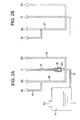
- Figs. 2a and 2B are schematic diagrams showing a communication passage and a lubricant supplying passage according to this embodiment.
- the gas compressor shown in Fig. 1 is equipped with a first supplying passage 12 which is formed in a rear side block 9 and which serves to communicate an oil sump 7 with a rear side block plain bearing 9a and with a high pressure supplying hole 10 through branching. Further, there is provided a third supplying passage 13 branching off from the first supplying passage 12, formed in the rear side block 9, the cylinder 3, and the front side block 8, and establishing communication between the oil sump 7 and a plain bearing 8a in the front side block.
- lubricant is supplied from the oil sump 7 to the plain bearings and other sliding portions of the gas compressor, to the sliding portions in the cylinder 3 shown in Fig. 8, such as the rotor 4, the flat groove 11, and the vanes 17, and to the compress ion chambers 5a to effect lubrication or sealing thereon.
- a second supply passage 14 further branching off from the branches off point 12b for the first supplying passage 12 and the third supplying passage 13, formed inside the rear side block 9, and establishing communication between the high pressure supplying hole 10 and the flat groove 11.
- a first pressure control valve 15 is provided in the second supplying passage 14.
- Figs. 2A and 2B are schematic diagrams showing a main structure portion of the first embodiment described above. These schematic diagram shows the relationship among the first supplying passage 12, the second supplying passage 14, the third supplying passage 13, the oil sump 7, the high pressure supplying hole 10, the flat groove 11, the plain bearing 8a in the front side block, the plain bearing 9a in the rear side block, and the first pressure control valve 15.
- this gas compressor constructed as described above, will be described.
- the high pressure refrigerant gas discharged into the high pressure supplying hole 10 passes the communication passage 21 formed by the first supplying passage 12 and the second supplying passage 14 before being discharged into the flat groove 11.
- the plurality of vane grooves 16 formed in the outer peripheral surface of the rotor 4 and arranged such that one of the vane grooves 16 is always under a suction/compression process.
- one of the vane grooves 16 is in communication with the flat groove 11, and the high pressure refrigerant gas is discharged into the vane groove bottom portion 16a in communication with the flat groove 11.
- the pressure of this high pressure refrigerant gas is applied to the vanes 17 mounted in the vane grooves 16 into which the high pressure refrigerant gas is discharged, whereby the vanes 17 project to a degree that they are pressed against the inner peripheral surface of the cylinder 3, dividing the cylinder chamber 5 into the compress ion chambers 5a.
- the high pressure supplying hole 10 prevents the vanes 17 from being separated from the inner peripheral surface of the cylinder 3 by the lubricant supplied thereto from the oil sump 7 through the first supplying passage 12. Further, during normal operation of the gas compressor, the first supplying passage 12 supplies lubricant from the oil sump 7 to the high pressure supplying hole 10, and the flat groove 11 supplies lubricant supplied through the clearance of the plain bearing to the vane groove bottom portions 16a.
- refrigerant gas compressed in the vane groove bottom portions 16a is discharged into the high pressure supplying hole 10. Further, the communication passage 21 formed by the first supplying passage 12 and the second supplying passage 14 supplies the high pressure refrigerant gas discharged into the high pressure supplying hole 10 to the flat groove 11. The flat groove 11 supplies the high pressure refrigerant gas supplied from the high pressure supplying hole 10 through the communication passage 21 to the vane groove bottom portions 16a.
- the communication passage 21 formed by the first supplying passage 12 and the second supplying passage 14 establishes communication between the high pressure supplying hole 10 and the flat groove 11. Due to the above construction, in addition to the centrifugal force due to the rotation of the rotor 4 and the vane back pressure due to the lubricant supplied to the vane groove bottom portions 16a from the flat groove 11, the vane back pressure obtained by supplying high pressure refrigerant gas to the vane groove bottom portions 16a, i.e., three forces in total, are applied to the vanes 17.
- the projectability of the vanes 17 is dramatically improved, and the vanes 17 divide the cylinders 5 immediately after the start of the compressor to define the compression chambers 5a, making it possible to perform suction/compression of refrigerant gas.
- Fig. 5 illustrates the starting performance of the compressor of this first embodiment.
- the graph of Fig. 5 compares the prior-art technique with this embodiment in terms of starting performance.
- Nc 800 rpm
- Pd pressure
- Ps pressure
- the suction chamber 0.420 MPaG to reproduce the state of the compressor at the start.
- the time it took for the vanes 17 to be pressed against the inner peripheral surface of the cylinder 3 in the suction/compression process was measured. Measurement was performed ten times each for the prior-art technique and this embodiment, obtaining the average values. The experiment results thus obtained are given in the graph.
- the results of the experiment showed that, in the prior-art technique, it took an average of 13.2 seconds for the vanes 17 to be pressed against the inner peripheral surface of the cylinder 3 in the suction/compression process, whereas, in this embodiment, it took an average of 0.9 seconds. That is, while in the prior-art technique it takes 13.2 seconds for the compressor to start sucking and compressing refrigerant gas after its start, it takes only 0.9 seconds in this embodiment for the suction and compression of refrigerant gas to be started.
- the above-mentioned communication passage 21 is formed by the first supplying passage 12 and the second supplying passage 14.
- the first supplying passage 12 through which the lubricant is supplied to the high pressure supplying hole 10, the first supplying passage 12 of the conventional gas compressor is used as it is, and it is only necessary to form the second supplying passage 14, which means modification of a conventional gas compressor can be effected at low cost.
- this first embodiment it is also possible for this first embodiment to adopt a construction in which the first pres sure control valve 15 is provided in the second supplying passage 14.
- the compressor performs the operation as described above in this embodiment upon starting; the suction/compression of refrigerant gas is immediately started, and high pressure refrigerant gas is discharged into the exhaust chamber 6, resulting in an increase in the pressure in the exhaust chamber 6.
- pressure in the exhaust chamber 6 increases, pressure is applied to the surface of the oil in the oil sump 7, and the lubricant in the oil sump 7 starts to flow through the supplying passages as high pressure lubricant.
- allowed to flow into the second supplying passage is lubricant to be caused to flow to various parts of the gas compressor through the first supplying passage 12 and the third supplying passage 13.
- the high pressure lubricant having flowed into the second supplying passage 14 starts to apply pressure to the first pressure control valve 15; when the difference in pressure between the output and input sides of the first pressure control valve 15 becomes equal to or larger than a predetermined value, the first pressure control valve 15 is brought into the closed state, interrupting the second supplying passage 14.
- the second supplying passage 14 is interrupted, and the communication passage 21 formed by the first supplying passage 12 and the second supplying passage 14 is brought out of communication, with the result that neither compressed refrigerant gas nor high pressure lubricant is discharged into the flat groove 11 through the second supplying passage 14.
- the compressor starts to suck and compress refrigerant gas
- the difference in pressure between the exhaust chamber 6 and the flat groove 11 becomes equal to or larger than a predetermined value
- the first pressure control valve 15 is brought into the closed state, whereby the supply of lubricant and high pressure refrigerant gas to be discharged into the flat groove 11 through the second supplying passage 14 is interrupted.
- the pressure of the lubricant for causing the first pressure control valve 15 to interrupt the second supplying passage 14 allows adjustment as appropriate, it is desirable for the pressure to be of a magnitude such that the second supplying passage 14 can be interrupted when the pressure of the discharge gas attains the pressure of the gas compressor during normal operation.
- the first pressure control valve 15 of this embodiment adopts a spherical valve body and a compression spring, and the pressure of discharge gas, which is the pressure of the gas compressor during normal operation, is applied to the valve body; when the pressure exceeds the urging force of the compression spring, the compression spring is compressed, and the valve body is brought into close contact with the valve seat, thus closing the second supplying passage 14.
- the construction of the first pressure control valve is not restricted to that of this embodiment; for instance, it is also possible for the valve body to be a conical one instead of the spherical one. Any type of valve body is applicable as appropriate in conformity with the specifications as long as it is capable of interrupting the second supplying passage 14 when the pressure of the discharge gas attains the pressure of the gas compressor during normal operation.
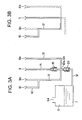
- FIGs. 3A and 3B are schematic diagrams showing the communication passage 21 and the lubricant supplying passage in the second embodiment of this invention.
- the communication passage 21 is formed in the rear side block, so that the longitudinal sectional view of the gas compressor will be omitted.
- the components which are the same as those of the prior-art technique and the first embodiment are indicated by the same reference numerals, and a detailed description of such components will be omitted.
- this second embodiment adopts the construction in which there are provided the communication passage 21 formed by the first supplying passage 12 and the second supplying passage 14, the third supplying passage 13, and the first pressure control valve 15 arranged in the second supplying passage 14.
- this second embodiment adopts a construction in which there is provided a second pressure control valve 20 at a position in the first supplying passage 12 on the downstream side of the oil sump 7 and on the upstream side of the branches off points 12a and 12b for the second supplying passage 14 and the third supplying passage 13.
- the first pressure control valve 15 When the pressure in the exhaust chamber 6 has been raised to a level equivalent to that during normal operation of the gas compressor, the first pressure control valve 15 is brought into the closed state and interrupts the second supplying passage 14. At the same time, when the pressure in the exhaust chamber 6 has been raised to a level equivalent to that during normal operation of the gas compressor, the second pressure control valve 20 is brought into the open state, and lubricant starts to flow from the oil sump 7 to the first supplying passage 12 and the third supplying passage 13, effecting lubrication and sealing on various parts of the gas compressor.
- the high pressure refrigerant gas discharged from the high pressure supplying hole 10 at the start of the compressor is not discharged into the oil sump 7, and it is possible to supply high pressure refrigerant gas efficiently to the flat groove 11 through the communication passage 21 formed by the first supplying passage 12 and the second supplying passage 14 .
- the vanes 17 project to a degree that they can be pressed against the inner peripheral surface of the cylinder 3, dividing the cylinder chamber 5 to define the compression chambers 5a. Then, the pressure in the exhaust chamber 6 is raised to a level equivalent to that during normal operation of the gas compressor, and the second pressure control valve 20 is brought into the open state, whereby lubricant is supplied from the oil sump 7 to various parts of the gas compressor.
- theprojectabilityof thevanes 17 is further improved, and the vanes 17 efficiently divides the cylinder chamber 5 from immediately after the operation start of the compressor, making it possible to suck and compress refrigerant gas.
- the requisite starting performance is ensured, and chattering, etc. at the time of starting is prevented as well.
- the pressure of the lubricant due to the pressure of the discharge gas for attaining the open state of the second pressure control valve 20 allows adjustment as appropriate, it is desirable for the pressure to be of a magnitude which causes the valve to be brought into the open state when the pressure of the discharge gas attains the pressure during normal operation of the gas compressor.
- a spherical valve body and a compression spring are used in the second pressure control valve 20; when the pressure of the discharge gas becomes that during normal operation of the gas compressor, and the pressure of the lubricant exceeds the urging force of the compression spring, the compression spring is compressed, and the valve body is separated from the valve seat to bring the first supplying passage 12 into the open state.
- the second pressure control valve 20 is not restricted to that of this embodiment; for instance, it may also adopt a conical valve body instead of the spherical one. It is also possible to adopt any type of valve body in conformity with the specifications as long as it is capable of bringing the first supplying passage 12 into the open state when the pressure of the discharge gas attains that during normal operation of the gas compressor.
- a third pressure control valve which is of the same construction and operation as the second pressure control valve 20 and which is adapted to be brought into the closed state when the difference between the pressure of the exhaust chamber 6 and the pressure in the third supplying passage 13 is not larger than a predetermined value.
- the projectability of thevanes 17 is further enhanced, making it possible to further enhance the above-mentioned effect.
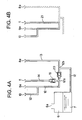
- FIGs. 4A and 4B are a schematic diagram showing the communication passage 21 and the lubricant supply passage of a third embodiment of this invention.
- the communication passage 21 in this embodiment is formed in the rear side block 9, so that a longitudinal sectional view of the gas compressor will be omitted.
- the components of this third embodiment which are the same as those of the prior-art technique and the first and second embodiments are indicated by the same reference numerals and a detailed description thereof will be omitted.
- this third embodiment adopts the construction in which there are provided the communication passage 21 formed by the first supplying passage 12 and the second supplying passage 14, the third supplying passage 13, and the first pressure control valve 15 arranged in the second supplying passage 14.
- the second supplying passage 14 branches off from the first supplying passage 12 at a point on the downstream side of the oil sump 7 and on the downstream side of the branches off point for the first supplying passage 12 and the third supplying passage 13. Further, the second pressure control valve 20 of this embodiment is provided in the first supplying passage 12 at a position between the branches off point 12a for the second supplying passage 14 and the branches off point 12b for the third supplying passage 13.
- the operation of the gas compressor of this third embodiment is the same as that of the first embodiment or the second embodiment, so that a description thereof will be omitted.
- the high pressure refrigerant gas discharged from the high pressure supplying hole 10 at the start of the compressor is not discharged into the oil sump 7 and the third supplying passage 13, and the high pressure refrigerant gas is efficiently supplied to the flat groove 11 through the communication passage 21 formed by the first supplying passage 12 and the second supplying passage 14.
- thevanes 17 project to a degree that they are pressed against the inner peripheral surface of the cylinder 3, and divide the cylinder chamber 5 to define the compression chambers 5a.
- the pressure of the discharge gas in the exhaust chamber 6 is raised to a level equivalent to that during normal operation of the gas compressor, and the second pressure control valve 20 is brought into the open state, so that lubricant is supplied from the oil sump 7 to various portions of the gas compressor.
- first and second embodiments regarding the first pressure control valve 15 and the second pressure control valve 20 of this third embodiment also, it is possible to adjust the requisite pressure for opening and closing the valve. Further, regarding the construction of the pressure control valve also, it may be selected as appropriate.
- the communication passage 21 for establishing communication between the high pressure supplying hole and the flat groove at the start of the compressor; at the time of starting the compressor, the high pressure refrigerant gas filling the high pressure supplying hole is discharged into the flat groove through the communication passage 21, and the high pressure refrigerant gas is supplied to the vane groove bottom portions communicating with the flat groove in the suction/compression process, so that deficiency in centrifugal force due to low speed rotation of the rotor and deficiency in lubricant supplied to the flat groove are compensated for to enable the vanes to project into the cylinder chamber, making it possible to improve the vane projectability at the start of the compressor, whereby the requisite starting performance is ensured no matter how adverse the conditions are, and it is possible to prevent chattering, etc. at the time of starting.
- the above-mentioned communication passage is formed by the first supplying passage and the second supplying passage, it is possible to use the first supplying passage of the conventional gas compressor as it is as the first supplying passage for supplying lubricant to the high pressure supplying hole, and it is only necessary to form the second supplying passage, which means modification of the conventional gas compressor can be effected at low cost.
- the high pressure refrigerant gas discharged from the high pressure supplying hole is not discharged into the oil sump and the third supplying passage at the start of the gas compressor, and is efficiently discharged into the flat groove, so that it is possible to further improve the vane proj ectability, and, no matter how adverse the conditions are, the requisite starting performance is further ensured, and chattering, etc. at the time of starting can be prevented more reliably.
Landscapes
- Engineering & Computer Science (AREA)
- Mechanical Engineering (AREA)
- General Engineering & Computer Science (AREA)
- Rotary Pumps (AREA)
- Applications Or Details Of Rotary Compressors (AREA)
Abstract
Description
Claims (10)
- A gas compressor for sucking in, compressing, and discharging refrigerant gas, the gas compressor comprising:an elliptical cylinder;a rotor rotatably arranged in the cylinder;vane grooves radially formed in the rotor;vanes provided in the vane grooves and capable of projecting and retracting radially with respect to the rotor;a flat groove adapted to communicate with vane groove bottom portions during a refrigerant gas sucking/compressing process;a high pressure supplying hole adapted to communicate with the vane groove bottom portions upon interception of the communication between the vane groove bottom portions and the flat groove in the refrigerant gas compressing process; anda communication passage adapted to establish communication between the flat groove and the high pressure supplying hole at the start of operation of the gas compressor.
- A gas compressor according to claim 1, further comprising:wherein the communication passage is formed by the first supplying passage and the second supplying passage.an exhaust chamber for temporarily storing refrigerant gas discharged from the cylinder;an oil sump formed in a lower portion of the exhaust chamber;a first supplying passage establishing communication between the oil sump and the high pressure supplying hole; anda second supplying passage branching off from the first supplying passage and communicating with the flat groove,
- A gas compressor according to claim 1, further comprising:a first pressure control valve which is provided in the communication passage and adapted to be brought into a closed state when the difference between a pressure in the exhaust chamber and a pressure in the flat groove becomes not less than a predetermined value.
- A gas compressor according to claim 2, further comprising:a first pressure control valve which is provided in the second supplying passage and adapted to be brought into a closed state when the difference between a pressure in the exhaust chamber and a pressure in the flat groove becomes not less than a predetermined value.
- A gas compressor according to claim 2, further comprising:a second pressure control valve which is provided in the first supplying passage on the downstream side of the oil sump and on the upstream side of a branches off point for the second supplying passage, and adapted to be brought into the closed state when the difference between the pressure in the exhaust chamber and a pressure at the branches off point for the second supplying passage becomes not more than a predetermined value.
- A gas compressor according to claim 4, further comprising:a second pressure control valve which is provided in the first supplying passage on the downstream side of the oil sump and on the upstream side of a branches off point for the second supplying passage, and adapted to be brought into the closed state when the difference between the pressure in the exhaust chamber and a pressure at the branches off point for the second supplying passage becomes not more than a predetermined value.
- A gas compressor according to claim 2, further comprising:a third supplying passage situated on the downstream side of the oil sump and branching off from the first supplying passage on the upstream side of the branches off point for the second supplying passage; anda second pressure control valve situated in the first supplying passage and between the branches off point for the second supplying passage and a branches off point for the third supplying passage and adapted to be brought into the closed state when the difference between the pressure in the exhaust chamber and the pressure at the branches off point for the second supplying passage is not more than a predetermined value.
- A gas compressor according to claim 4, further comprising:a third supplying passage situated on the downstream side of the oil sump and branching off from the first supplying passage on the upstream side of the branches off point for the second supplying passage; anda second pressure control valve situated in the first supplying passage and between the branches off point for the second supplying passage and a branches off point for the third supplying passage and adapted to be brought into the closed state when the difference between the pressure in the exhaust chamber and the pressure at the branches off point for the second supplying passage is not more than a predetermined value.
- A gas compressor according to claim 4, further comprising:a third supplying passage further branching off from the branches off point for the second supplying passage and adapted to supply lubricant to a front portion of the interior of the gas compressor main body; anda third pressure control valve situated at a position in the gas compressor main body in front of the oil sump and inside the third supplying passage behind the branches off point and adapted to be brought into the closed state when the difference between the pressure in the exhaust chamber and a pressure in the third supplying passages is not more than a predetermined value.
- A gas compressor according to claim 5, further comprising:a third supplying passage further branching off from the branches off point for the second supplying passage and adapted to supply lubricant to a front portion of the interior of the gas compressor main body; anda third pressure control valve situated at a position in the gas compressor main body in front of the oil sump and inside the third supplying passage behind the branches off point and adapted to be brought into the closed state when the difference between the pressure in the exhaust chamber and a pressure in the third supplying passages is not more than a predetermined value.
Applications Claiming Priority (2)
| Application Number | Priority Date | Filing Date | Title |
|---|---|---|---|
| JP2002255330A JP4095869B2 (en) | 2002-08-30 | 2002-08-30 | Gas compressor |
| JP2002255330 | 2002-08-30 |
Publications (3)
| Publication Number | Publication Date |
|---|---|
| EP1394417A2 true EP1394417A2 (en) | 2004-03-03 |
| EP1394417A3 EP1394417A3 (en) | 2004-03-31 |
| EP1394417B1 EP1394417B1 (en) | 2006-05-31 |
Family
ID=31492675
Family Applications (1)
| Application Number | Title | Priority Date | Filing Date |
|---|---|---|---|
| EP03254211A Expired - Lifetime EP1394417B1 (en) | 2002-08-30 | 2003-07-02 | Rotary vane gas compressor |
Country Status (6)
| Country | Link |
|---|---|
| US (1) | US6929457B2 (en) |
| EP (1) | EP1394417B1 (en) |
| JP (1) | JP4095869B2 (en) |
| CN (1) | CN100390419C (en) |
| DE (1) | DE60305589T2 (en) |
| MY (1) | MY130901A (en) |
Families Citing this family (3)
| Publication number | Priority date | Publication date | Assignee | Title |
|---|---|---|---|---|
| US10087934B2 (en) * | 2015-07-27 | 2018-10-02 | Kabushiki Kaisha Toyota Jidoshokki | Vane compressor |
| CN105402130B (en) * | 2015-11-20 | 2018-08-07 | 珠海格力电器股份有限公司 | Compressor vane back pressure structure and compressor, air conditioner |
| JP7061618B2 (en) * | 2017-04-07 | 2022-04-28 | スタックポール インターナショナル エンジニアード プロダクツ,リミテッド. | Epitrochoid vacuum pump |
Family Cites Families (14)
| Publication number | Priority date | Publication date | Assignee | Title |
|---|---|---|---|---|
| JPS57146092A (en) * | 1981-03-05 | 1982-09-09 | Matsushita Electric Ind Co Ltd | Rotary compressor |
| JPS5874890A (en) * | 1981-10-30 | 1983-05-06 | Hitachi Ltd | Rotary vane compressor |
| JPS58104381U (en) * | 1981-12-08 | 1983-07-15 | セイコ−精機株式会社 | gas compressor |
| JPS58197491A (en) * | 1982-05-14 | 1983-11-17 | Toyoda Autom Loom Works Ltd | Rotary compressor with slide vanes |
| JPS6069380U (en) * | 1983-10-18 | 1985-05-16 | 株式会社ボッシュオートモーティブ システム | vane compressor |
| JPS60145476A (en) * | 1983-12-29 | 1985-07-31 | Matsushita Electric Ind Co Ltd | Oil feeding apparatus for rotary vane type compressor |
| JPS60252188A (en) * | 1984-05-28 | 1985-12-12 | Hitachi Ltd | Movable vane compressor |
| JPS61116087A (en) * | 1984-11-09 | 1986-06-03 | Hitachi Ltd | vane compressor |
| US4664608A (en) * | 1985-11-04 | 1987-05-12 | General Electric Company | Rotary compressor with reduced friction between vane and vane slot |
| US4936761A (en) * | 1986-12-03 | 1990-06-26 | Matsushita Electric Industrial Co., Ltd. | Vane backpressure providing apparatus for sliding vane type compressor |
| JPH01155095A (en) * | 1987-12-10 | 1989-06-16 | Suzuki Motor Co Ltd | Vane type rotary compressor |
| US5470214A (en) * | 1992-12-17 | 1995-11-28 | Goldstar Co., Ltd. | Lubricating device for horizontal type hermetic compressor |
| KR100336134B1 (en) * | 1999-07-28 | 2002-05-09 | 구자홍 | Silent rotary compressor |
| JP2002227784A (en) * | 2001-02-05 | 2002-08-14 | Seiko Instruments Inc | Vane rotary type gas compressor |
-
2002
- 2002-08-30 JP JP2002255330A patent/JP4095869B2/en not_active Expired - Fee Related
-
2003
- 2003-07-02 DE DE60305589T patent/DE60305589T2/en not_active Expired - Lifetime
- 2003-07-02 EP EP03254211A patent/EP1394417B1/en not_active Expired - Lifetime
- 2003-07-09 US US10/616,383 patent/US6929457B2/en not_active Expired - Fee Related
- 2003-07-11 MY MYPI20032614A patent/MY130901A/en unknown
- 2003-09-01 CN CNB031556620A patent/CN100390419C/en not_active Expired - Fee Related
Also Published As
| Publication number | Publication date |
|---|---|
| US20040126262A1 (en) | 2004-07-01 |
| EP1394417A3 (en) | 2004-03-31 |
| DE60305589D1 (en) | 2006-07-06 |
| CN1487198A (en) | 2004-04-07 |
| EP1394417B1 (en) | 2006-05-31 |
| JP4095869B2 (en) | 2008-06-04 |
| CN100390419C (en) | 2008-05-28 |
| US6929457B2 (en) | 2005-08-16 |
| DE60305589T2 (en) | 2006-11-16 |
| MY130901A (en) | 2007-07-31 |
| JP2004092521A (en) | 2004-03-25 |
Similar Documents
| Publication | Publication Date | Title |
|---|---|---|
| CN100419269C (en) | a gas compressor | |
| EP0600313B1 (en) | Lubrication for rotary compressor | |
| JP5706827B2 (en) | Screw compressor | |
| CA1066678A (en) | Rotary compressor | |
| US4611977A (en) | Vane compressor with vane back pressure adjustment | |
| US6929457B2 (en) | Gas compressor | |
| US4810177A (en) | Vane compressor with vane back pressure adjustment | |
| JPS6149189A (en) | Variable displacement type rotary compressor | |
| JP2006112331A (en) | Compressor | |
| JP2001140781A (en) | Gas compressor | |
| JP4142863B2 (en) | Gas compressor | |
| JP3745915B2 (en) | Gas compressor | |
| JP2006194111A (en) | Vane rotary compressor | |
| JP3018075B2 (en) | Vane rotary type variable displacement compressor | |
| JP3692236B2 (en) | Gas compressor | |
| JP4076764B2 (en) | Gas compressor | |
| JPS63173893A (en) | Gas compressor | |
| JP2964193B2 (en) | Vane type compressor | |
| JP3383602B2 (en) | Gas compressor | |
| JP2004052607A (en) | Gas compressor | |
| JP2001059487A (en) | Gas compressor | |
| JP2000265983A (en) | Gas compressor | |
| JPH0320556Y2 (en) | ||
| WO2014103974A1 (en) | Gas compressor | |
| JP2002048081A (en) | Gas compressor |
Legal Events
| Date | Code | Title | Description |
|---|---|---|---|
| PUAI | Public reference made under article 153(3) epc to a published international application that has entered the european phase |
Free format text: ORIGINAL CODE: 0009012 |
|
| PUAL | Search report despatched |
Free format text: ORIGINAL CODE: 0009013 |
|
| AK | Designated contracting states |
Kind code of ref document: A2 Designated state(s): AT BE BG CH CY CZ DE DK EE ES FI FR GB GR HU IE IT LI LU MC NL PT RO SE SI SK TR |
|
| AX | Request for extension of the european patent |
Extension state: AL LT LV MK |
|
| AK | Designated contracting states |
Kind code of ref document: A3 Designated state(s): AT BE BG CH CY CZ DE DK EE ES FI FR GB GR HU IE IT LI LU MC NL PT RO SE SI SK TR |
|
| AX | Request for extension of the european patent |
Extension state: AL LT LV MK |
|
| RAP1 | Party data changed (applicant data changed or rights of an application transferred) |
Owner name: CALSONIC COMPRESSOR MANUFACTURING INC. |
|
| 17P | Request for examination filed |
Effective date: 20040831 |
|
| AKX | Designation fees paid |
Designated state(s): DE FR GB |
|
| 17Q | First examination report despatched |
Effective date: 20041222 |
|
| GRAP | Despatch of communication of intention to grant a patent |
Free format text: ORIGINAL CODE: EPIDOSNIGR1 |
|
| GRAS | Grant fee paid |
Free format text: ORIGINAL CODE: EPIDOSNIGR3 |
|
| GRAA | (expected) grant |
Free format text: ORIGINAL CODE: 0009210 |
|
| AK | Designated contracting states |
Kind code of ref document: B1 Designated state(s): DE FR GB |
|
| REG | Reference to a national code |
Ref country code: GB Ref legal event code: FG4D |
|
| RIC1 | Information provided on ipc code assigned before grant |
Ipc: F04C 28/00 20060101ALI20060407BHEP Ipc: F01C 21/08 20060101ALI20060407BHEP Ipc: F04C 18/344 20060101AFI20060407BHEP |
|
| REF | Corresponds to: |
Ref document number: 60305589 Country of ref document: DE Date of ref document: 20060706 Kind code of ref document: P |
|
| ET | Fr: translation filed | ||
| PLBE | No opposition filed within time limit |
Free format text: ORIGINAL CODE: 0009261 |
|
| STAA | Information on the status of an ep patent application or granted ep patent |
Free format text: STATUS: NO OPPOSITION FILED WITHIN TIME LIMIT |
|
| 26N | No opposition filed |
Effective date: 20070301 |
|
| PGFP | Annual fee paid to national office [announced via postgrant information from national office to epo] |
Ref country code: DE Payment date: 20140625 Year of fee payment: 12 |
|
| PGFP | Annual fee paid to national office [announced via postgrant information from national office to epo] |
Ref country code: FR Payment date: 20140708 Year of fee payment: 12 Ref country code: GB Payment date: 20140702 Year of fee payment: 12 |
|
| REG | Reference to a national code |
Ref country code: DE Ref legal event code: R119 Ref document number: 60305589 Country of ref document: DE |
|
| GBPC | Gb: european patent ceased through non-payment of renewal fee |
Effective date: 20150702 |
|
| PG25 | Lapsed in a contracting state [announced via postgrant information from national office to epo] |
Ref country code: GB Free format text: LAPSE BECAUSE OF NON-PAYMENT OF DUE FEES Effective date: 20150702 Ref country code: DE Free format text: LAPSE BECAUSE OF NON-PAYMENT OF DUE FEES Effective date: 20160202 |
|
| REG | Reference to a national code |
Ref country code: FR Ref legal event code: ST Effective date: 20160331 |
|
| PG25 | Lapsed in a contracting state [announced via postgrant information from national office to epo] |
Ref country code: FR Free format text: LAPSE BECAUSE OF NON-PAYMENT OF DUE FEES Effective date: 20150731 |