EP0600313B1 - Lubrication for rotary compressor - Google Patents
Lubrication for rotary compressor Download PDFInfo
- Publication number
- EP0600313B1 EP0600313B1 EP93118583A EP93118583A EP0600313B1 EP 0600313 B1 EP0600313 B1 EP 0600313B1 EP 93118583 A EP93118583 A EP 93118583A EP 93118583 A EP93118583 A EP 93118583A EP 0600313 B1 EP0600313 B1 EP 0600313B1
- Authority
- EP
- European Patent Office
- Prior art keywords
- oil
- bearing
- rotary compressor
- rear side
- shaft
- Prior art date
- Legal status (The legal status is an assumption and is not a legal conclusion. Google has not performed a legal analysis and makes no representation as to the accuracy of the status listed.)
- Expired - Lifetime
Links
- 238000005461 lubrication Methods 0.000 title claims description 8
- 230000006835 compression Effects 0.000 claims description 11
- 238000007906 compression Methods 0.000 claims description 11
- XEEYBQQBJWHFJM-UHFFFAOYSA-N Iron Chemical compound [Fe] XEEYBQQBJWHFJM-UHFFFAOYSA-N 0.000 claims description 6
- XAGFODPZIPBFFR-UHFFFAOYSA-N aluminium Chemical compound [Al] XAGFODPZIPBFFR-UHFFFAOYSA-N 0.000 claims description 5
- 229910052782 aluminium Inorganic materials 0.000 claims description 5
- 229910052742 iron Inorganic materials 0.000 claims description 3
- 239000002826 coolant Substances 0.000 description 9
- 238000004378 air conditioning Methods 0.000 description 4
- 238000010276 construction Methods 0.000 description 3
- 238000004519 manufacturing process Methods 0.000 description 2
- 238000007599 discharging Methods 0.000 description 1
Images


Classifications
-
- F—MECHANICAL ENGINEERING; LIGHTING; HEATING; WEAPONS; BLASTING
- F04—POSITIVE - DISPLACEMENT MACHINES FOR LIQUIDS; PUMPS FOR LIQUIDS OR ELASTIC FLUIDS
- F04C—ROTARY-PISTON, OR OSCILLATING-PISTON, POSITIVE-DISPLACEMENT MACHINES FOR LIQUIDS; ROTARY-PISTON, OR OSCILLATING-PISTON, POSITIVE-DISPLACEMENT PUMPS
- F04C29/00—Component parts, details or accessories of pumps or pumping installations, not provided for in groups F04C18/00 - F04C28/00
- F04C29/02—Lubrication; Lubricant separation
Definitions
- the present invention relates in general to compressors, and more particularly to compressors of a rotary type as indicated in the preamble portion of claim 1, which is suitable for use in an automotive air conditioning system. More specifically, the present invention is concerned with rotary compressors of a type in which a measure is employed for adjusting the amount of lubrication oil fed to frictionally engaged members, such as bearings for a rotation shaft and the like.
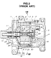
- Figs. 5 and 6 show the conventional rotary compressor which is disclosed in Japanese Utility Model Second Provisional Publication 61-187991.
- the compressor comprises a casing 1 in which a cylinder 2 is stationarily installed.
- the cylinder 2 is sandwiched between front and rear side blocks 4 and 5.
- bolts are used for uniting the cylinder 2 and the front and rear side blocks 4 and 5.
- the cylinder 2 is formed with an oval bore 3 with which a rotor unit 6 is incorporated.
- the rotor unit 6 comprises a shaft 10 and a rotor proper 7 which is connected to the shaft 10 via spline connection.
- the rotor proper 7 is rotatably disposed in the oval bore 3 having two crescent clearances defined therebetween. That is, each clearance is defined between an outer surface of the rotor proper 7 and an inner surface 3a of the oval bore 3.
- the rotor proper 7 is formed with five radially extending vane grooves 9 each receiving therein a sliding vane 8.
- each compression chamber C is defined by adjacent sliding vanes 8, the outer surface of the rotor proper 7 and the inner surface 3a of the oval bore 3.
- each compression chamber C varies the volume and thus the coolant in the compression chamber C is pressurized.
- the pressurized coolant is then led into a connection passage 15 through a discharge opening 13 of the cylinder 2 against a discharging valve 14.
- Designated by reference numeral 14a is a protection plate for the valve 14.
- the pressurized coolant flows in the connection passage 15 and impinges against an oil separator 16 which projects into a space "S" defined in the casing 1.
- the coolant is then discharged to the outside through an outlet port 17.
- any oil O is separated from the coolant and falls into an oil reservoir 18 which forms a lower portion of the space "S".
- the oil reservoir 18 is defined by a bottom wall of the casing 1 and the rear side block 5. Due to the pressure of the pressurized coolant in the oil reservoir 18 as shown by arrows "P", the oil O is forced to flow into both front and rear oil passages 19 and 20.
- the front passage 19 includes a passage 19a formed in the cylinder 2 and a passage 19b formed in the front side block 4.
- the oil O in the front oil passage 19 is led to a front sliding bearing 22f and to a shaft seal 23 and back pressure chambers 24 for the sliding vanes 8.
- the oil O in the rear oil passage 20 is led to a rear sliding bearing 22r and to the back pressure chambers 24.
- a lower portion of the rear side block 5 is formed with an oil inlet opening 30 through which the oil O in the oil reservoir 18 is led into the front and rear oil passages 19 and 20. Lubrication of the bearings 22f and 22r and the sliding vanes 8 is thus achieved.
- each oil passage 19 or 20 to the back pressure chambers 24 is made through an annular clearance which is defined between the shaft 10 and the front or rear bearing 22f or 22r. Due to the pressure of the pressurized oil in the back pressure chambers 24 as well as the afore-mentioned centrifugal force, the sliding vanes 8 are biased radially outward, that is, toward the rounded inner surface 3a of the oval bore 3.
- Some of conventional rotary compressors use a gear pump for pressurizing the oil O in the oil reservoir 18.
- the shaft 10 of the rotor unit 6 is constructed of iron, while the front and rear sliding bearings 22f and 22r are constructed of aluminum.
- the sliding bearing 22f or 22r is so constructed as to vary the amount of oil fed to a given portion in accordance with the size of a clearance defined between the bearing 22f or 22r and the shaft 10. Accordingly, the amount of oil fed to the sliding bearing and to the given portion varies in accordance with both:
- the compressor when employed in an automotive air conditioning system, the compressor is subjected to ON/OFF operation for keeping the temperature in a vehicle cabin at a predetermined temperature.
- the compressor is stopped at the time when the clearance between the bearing 22f or 22r and the shaft 10 has been increased to a certain degree due to increase in temperature of the interior of the compressor, the oil O is forced to flow from the oil reservoir 18 to an intake chamber 11' through the front oil passage 19 and the front bearing 22f. That is, under this condition, the intake chamber 11' is relatively low in pressure.
- the compressor is restarted, the oil O in the intake chamber 11' is sucked into the compression chambers C and thus pressurized, so that the force needed for driving the rotor unit 6 is increased temporarily.
- a rotary compressor which comprises a casing; a cylinder unit tightly installed in the casing, the cylinder unit having an enclosed rounded bore formed therein; a rotor unit including a shaft and a rotor proper, the shaft extending along an axis of the casing in such a manner that the rotor proper is rotatably disposed in the rounded bore; a plurality of sliding vanes slidably received in radially extending grooves formed in the rotor unit; means for defining an inlet port exposed to compression chambers, each compression chamber being defined by adjacent two sliding vanes, an inner wall of the rounded bore and an outer wall of the rotor proper; means for defining an outlet port exposed to the compression chambers; bearing means for bearing the shaft relative to the cylinder unit; means for defining an oil reservoir in which lubrication oil is reserved; and oil passage means for defining in the cylinder unit at least one oil passage through which the lubrication oil flows from the oil reservoir to the bearing means,
- a rotary compressor 100 which is a first embodiment of the present invention.
- the compressor 100 is similar in construction to the above-mentioned conventional compressor of Figs. 5 and 6, only parts and constructions which are different from those of the conventional one will be described in the following for ease of description. The same parts and constructions are designed by the same numerals.
- the front and rear oil passages 19 and 20 are respectively formed with flow restrictors "Of" and “Or” for controlling the flow of oil O in the oil passages 19 and 20.
- both the flow restrictors "Of" and “Or” are defined or formed by the rear side block 5, as is shown in Fig. 1.
- FIG. 2 there is shown a second embodiment 200 of the invention in which only the front oil passage 19 is formed with the flow restrictor "Of".
- the amount of oil fed to the rear bearing 22r through the rear oil passage 20 is increased. This is preferable because the rear bearing 22r is more heated than the front bearing 22f because the rear bearing 22r is positioned near the connection passage 15 through which the pressurized and heated coolant flows.
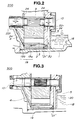
- FIG. 3 there is shown a third embodiment 300 of the present invention.
- the front and rear side blocks 4 and 5 are constructed of aluminum, and these side blocks 4 and 6 bear the shaft 10 of the rotor unit 6 by themselves.
- lubrication of the bearing portions is effected by the oil "O" led from the oil reservoir 18 through the front and rear oil passages 19 and 20. Only the front oil passage 19 is formed with a flow restrictor "Of".
- iron bushes may be used in place of the above-mentioned sliding bearings which are constructed of aluminum.
- At least one of the oil passages 19 and 20 is formed with a flow restrictor "Of" or "Or".
- a flow restrictor "Of" or "Or” the flow restrictor of the invention is free of the drawbacks possessed by the compressor of the above-mentioned US Patent.
Landscapes
- Engineering & Computer Science (AREA)
- Mechanical Engineering (AREA)
- General Engineering & Computer Science (AREA)
- Rotary Pumps (AREA)
- Applications Or Details Of Rotary Compressors (AREA)
Description
- The present invention relates in general to compressors, and more particularly to compressors of a rotary type as indicated in the preamble portion of
claim 1, which is suitable for use in an automotive air conditioning system. More specifically, the present invention is concerned with rotary compressors of a type in which a measure is employed for adjusting the amount of lubrication oil fed to frictionally engaged members, such as bearings for a rotation shaft and the like. - Hitherto, various rotary compressors have been proposed and put into practical use particularly in the field of automotive air conditioning system.
- In order to clarify the task of the present invention, one of the conventional rotary compressors will be described prior to making a detailed description of the present invention.
- Figs. 5 and 6 show the conventional rotary compressor which is disclosed in Japanese Utility Model Second Provisional Publication 61-187991.
- As is seen from Fig. 5, the compressor comprises a
casing 1 in which acylinder 2 is stationarily installed. Thecylinder 2 is sandwiched between front andrear side blocks cylinder 2 and the front andrear side blocks - As is seen from Figs. 5 and 6, the
cylinder 2 is formed with anoval bore 3 with which arotor unit 6 is incorporated. Therotor unit 6 comprises ashaft 10 and a rotor proper 7 which is connected to theshaft 10 via spline connection. As is seen from Fig. 6, the rotor proper 7 is rotatably disposed in theoval bore 3 having two crescent clearances defined therebetween. That is, each clearance is defined between an outer surface of the rotor proper 7 and an inner surface 3a of theoval bore 3. The rotor proper 7 is formed with five radially extendingvane grooves 9 each receiving therein a slidingvane 8. - When the rotor proper 7 is rotated by a drive means such as engine or the like, the sliding
vanes 8 are forced to project outward due to generated centrifugal force, which causes tops of thevanes 8 to contact to and slide along the rounded inner surface 3a of theoval bore 3. As will be described hereinafter, in addition to the centrifugal force, a hydraulic pressure is constantly applied to rear ends of the slidingvanes 8 to bias the same radially outward under operation of the compressor. - Due rotation of the rotor proper 7, a coolant is introduced into compression chambers C through an inlet port 11 formed in the
casing 1 and aninlet opening 12 formed in thefront side block 4, as is indicated by arrows illustrated by broken lines in Fig. 5. Each compression chamber C is defined by adjacentsliding vanes 8, the outer surface of the rotor proper 7 and the inner surface 3a of theoval bore 3. - As is seen from Fig. 6, with rotation of the rotor proper 6, each compression chamber C varies the volume and thus the coolant in the compression chamber C is pressurized. As is seen from Fig. 5, the pressurized coolant is then led into a connection passage 15 through a discharge opening 13 of the
cylinder 2 against a dischargingvalve 14. Designated by reference numeral 14a is a protection plate for thevalve 14. The pressurized coolant flows in the connection passage 15 and impinges against anoil separator 16 which projects into a space "S" defined in thecasing 1. The coolant is then discharged to the outside through anoutlet port 17. - When the coolant impinges against the
oil separator 16, any oil O is separated from the coolant and falls into anoil reservoir 18 which forms a lower portion of the space "S". As shown, theoil reservoir 18 is defined by a bottom wall of thecasing 1 and therear side block 5. Due to the pressure of the pressurized coolant in theoil reservoir 18 as shown by arrows "P", the oil O is forced to flow into both front andrear oil passages front passage 19 includes apassage 19a formed in thecylinder 2 and apassage 19b formed in thefront side block 4. - The oil O in the
front oil passage 19 is led to a front sliding bearing 22f and to ashaft seal 23 andback pressure chambers 24 for the slidingvanes 8. The oil O in therear oil passage 20 is led to a rear sliding bearing 22r and to theback pressure chambers 24. - A lower portion of the
rear side block 5 is formed with an oil inlet opening 30 through which the oil O in theoil reservoir 18 is led into the front andrear oil passages bearings vanes 8 is thus achieved. - As shown in Fig. 5, the oil flow from each
oil passage back pressure chambers 24 is made through an annular clearance which is defined between theshaft 10 and the front or rear bearing 22f or 22r. Due to the pressure of the pressurized oil in theback pressure chambers 24 as well as the afore-mentioned centrifugal force, the slidingvanes 8 are biased radially outward, that is, toward the rounded inner surface 3a of theoval bore 3. Some of conventional rotary compressors use a gear pump for pressurizing the oil O in theoil reservoir 18. - The
shaft 10 of therotor unit 6 is constructed of iron, while the front and rear slidingbearings shaft 10. Accordingly, the amount of oil fed to the sliding bearing and to the given portion varies in accordance with both: - a) the differential pressure between the
oil reservoir 18 and theback pressure chambers 24 for the slidingvanes 8, and - b) the size of the clearance between the
bearing shaft 10, the size being varied due to a differential thermal expansion and a wearing difference therebetween. - Thus, when the compressor is forced to operate under a highly loaded condition, the temperature of the
bearing shaft 10 increases. Thus, in this condition, the oil O which can be reserved in theoil reservoir 18 is reduced, which however induces a possibility of conveying a flash gas to thebearings oil passages - As is understood from the line "A" of the graph of Fig. 4, the amount of oil O fed to the
bearings bearings - As is known, when employed in an automotive air conditioning system, the compressor is subjected to ON/OFF operation for keeping the temperature in a vehicle cabin at a predetermined temperature. However, when the compressor is stopped at the time when the clearance between the
bearing shaft 10 has been increased to a certain degree due to increase in temperature of the interior of the compressor, the oil O is forced to flow from theoil reservoir 18 to an intake chamber 11' through thefront oil passage 19 and the front bearing 22f. That is, under this condition, the intake chamber 11' is relatively low in pressure. When, thereafter, the compressor is restarted, the oil O in the intake chamber 11' is sucked into the compression chambers C and thus pressurized, so that the force needed for driving therotor unit 6 is increased temporarily. - When the
oil reservoir 18 fails to keep therein a sufficient amount of oil O, the durability of the compressor is lowered. In fact, it tends to occur that the tops of the slidingvanes 8 fail to smoothly contact the rounded inner surface 3a of theoval bore 3, which causes generation of noise and vibration of the compressor. - In order to solve the above-mentioned drawbacks, one measure was proposed which is disclosed in US patent 4,875,835. The disclosure of said US patent document corresponds to the features of the preamble portion of
claim 1. - In the measure of this Patent, there are employed flow restrictors which are thrust into oil passages corresponding to the
oil passage - However, even the measure of the Patent has the following new drawbacks.
- 1) Because the flow restrictors are separate members thrust into the oil passages, there is the possibility of disconnection of the flow restrictors from the oil passages. In fact, when the compressor is used in an automotive air conditioning system, vibration of the vehicle tends to increase the possibility.
- 2) Production of the oil passages is difficult or at least troublesome because of the inclined orientation of them. Furthermore, the work for thrusting the flow restrictors into such inclined passages is difficult.
- 3) For achieving a stable settlement of the flow restrictors in the oil passages, the passages should be machined very precisely.
- It is therefore an object of the present invention to provide a rotary compressor which is free of the above-mentioned drawbacks, so that flow restrictors are prevented from being disconnected from the oil passage, production of the oil passage is made easier and more accurate. This object is solved by a rotary compressor having the features of
claim 1. - According to the present invention, there is provided a rotary compressor which comprises a casing; a cylinder unit tightly installed in the casing, the cylinder unit having an enclosed rounded bore formed therein; a rotor unit including a shaft and a rotor proper, the shaft extending along an axis of the casing in such a manner that the rotor proper is rotatably disposed in the rounded bore; a plurality of sliding vanes slidably received in radially extending grooves formed in the rotor unit; means for defining an inlet port exposed to compression chambers, each compression chamber being defined by adjacent two sliding vanes, an inner wall of the rounded bore and an outer wall of the rotor proper; means for defining an outlet port exposed to the compression chambers; bearing means for bearing the shaft relative to the cylinder unit; means for defining an oil reservoir in which lubrication oil is reserved; and oil passage means for defining in the cylinder unit at least one oil passage through which the lubrication oil flows from the oil reservoir to the bearing means, wherein (at least one) oil passage is formed with a flow restrictor which is integrally formed with the cylinder unit.
- Other objects and advantages of the present invention will become apparent from the following description when taken in conjunction with the accompanying drawings, in which:
- Fig. 1 is a sectional view of a rotary compressor which is a first embodiment of the present invention;
- Fig. 2 is an enlarged sectional view of an essential part of a second embodiment of the present invention;
- Fig. 3 is a view similar to Fig. 2, but showing a third embodiment of the present invention;
- Fig. 4 is a graph showing the performance of the present invention in terms of the relationship between the temperature of the interior of a compressor and the amount of oil fed to a bearing;
- Fig. 5 is a view similar to Fig. 1, but showing a prior art rotary compressor; and
- Fig. 6 is a sectional view taken along the line VI-VI of Fig. 5.
- Referring to Fig. 1, there is shown a
rotary compressor 100 which is a first embodiment of the present invention. - Since the
compressor 100 is similar in construction to the above-mentioned conventional compressor of Figs. 5 and 6, only parts and constructions which are different from those of the conventional one will be described in the following for ease of description. The same parts and constructions are designed by the same numerals. - In the first embodiment of the present invention, the front and
rear oil passages oil passages - It is to be noted that both the flow restrictors "Of" and "Or" are defined or formed by the
rear side block 5, as is shown in Fig. 1. - Due to provision of the flow restrictors "Of" and "Or", it never occurs that excessive amount of oil is fed to the
bearings oil reservoir 18 even when the differential pressure between theoil reservoir 18 and thebearing shaft 10 increases. Furthermore, due to provision of such flow restrictors "Of" and "Or", it never occurs that the oil "O" flows toward the intake chamber even when the compressor is stopped at the time when the clearance between the bearing 22f or 22r and theshaft 10 has been increased due to increase in temperature of the interior of the compressor. - These phenomena will be understood from the graph of Fig. 4 in which the solid line "B" shows a case wherein the oil feeding control is carried out by only the flow restrictors "Of" and "Or", and the broken line "C" shows a case wherein the oil feed control is carried out by both the flow restrictors "Of" and "Or" and the clearance between the bearing 22f or 22r and the
shaft 10. - Referring to Fig. 2, there is shown a
second embodiment 200 of the invention in which only thefront oil passage 19 is formed with the flow restrictor "Of". In this embodiment, the amount of oil fed to therear bearing 22r through therear oil passage 20 is increased. This is preferable because therear bearing 22r is more heated than thefront bearing 22f because therear bearing 22r is positioned near the connection passage 15 through which the pressurized and heated coolant flows. - Referring to Fig. 3, there is shown a
third embodiment 300 of the present invention. In this embodiment, the front and rear side blocks 4 and 5 are constructed of aluminum, and theseside blocks shaft 10 of therotor unit 6 by themselves. Of course, lubrication of the bearing portions is effected by the oil "O" led from theoil reservoir 18 through the front andrear oil passages front oil passage 19 is formed with a flow restrictor "Of". - If desired, iron bushes may be used in place of the above-mentioned sliding bearings which are constructed of aluminum.
- As will be understood from the foregoing description, in accordance with the present invention, at least one of the
oil passages bearings rear side block 5, the compressor of the invention is free of the drawbacks possessed by the compressor of the above-mentioned US Patent.
Claims (9)
- A rotary compressor (100, 200, 300) comprising:a casing (1),a cylinder unit (2, 4, 5) tightly installed in said casing (1), said cylinder unit having an enclosed rounded bore (3) formed therein,a rotor unit (6) including a shaft (10) and a rotor proper (7), said shaft (10) extending along an axis of said casing in such a manner that the rotor proper (7) is rotatably disposed in said rounded bore (3),a plurality of sliding vanes (8) slidably received in radially extending grooves (9) formed in said rotor unit (6),means for defining an inlet port (11) exposed to compression chambers (C), each compression chamber (C) being defined by adjacent two sliding vanes (8), an inner wall (3a) of said rounded bore (3) and an outer wall of said rotor proper (7),means for defining an outlet port (17) exposed to said compression chambers (C),bearing means (22f, 22r) for bearing said shaft (10) relative to said cylinder unit,means for defining an oil reservoir (18) in which lubrication oil (O) is reserved, andoil passage means (19, 20) for defining in said cylinder unit at least one oil passage through which the lubrication oil (0) flows from said oil reservoir (18) to said bearing means (22f, 22r),wherein at least one said oil passage (19, 20) is provided with a flow restrictor (Of, Or),characterized in that
said flow restrictor (Of, Or) is integrally formed with said cylinder unit. - A rotary compressor as claimed in claim 1, in which said cylinder unit comprises a cylinder (2), and front and rear side blocks (4, 5) for putting therebetween said cylinder (2) thereby to define said enclosed rounded bore (3) therebetween.
- A rotary compressor as claimed in claim 1, in which said bearing means (22f, 22r) comprises a front bearing (22f) which bears said shaft (10) relative to said front side block (4) and a rear bearing (22r) which bears said shaft (10) relative to said rear side block (5), and in which said oil passage means (19, 20) comprises means for defining a front oil passage (19) which extends from said oil reservoir (18) to said front bearing (22f) and means for defining a rear oil passage (20) which extends from said oil reservoir (18) to said rear bearing (22r).
- A rotary compressor as claimed in claim 3, in which said front and rear oil passages (19, 20) are formed with respective flow restrictors which are defined by said rear side blocks (5).
- A rotary compressor as claimed in claim 3, in which said front bearing (22f) is positioned near said inlet port (11) and said rear bearing (22r) is positioned near said outlet port (17).
- A rotary compressor as claimed in claim 5, in which said rear side block (5) is formed with a common inlet port (30) through which the oil (O) flows into both said front and second oil passages (19, 20).
- A rotary compressor as claimed in claim 5, in which only the front oil passage (19) is formed with a flow restrictor (Of) which is defined by said rear side block (5).
- A rotary compressor as claimed in claim 2, in which said bearing means (22r, 22f) comprises a bearing part defined by said front side block (4) and another bearing part defined by said rear side block (5), said front and rear side blocks (4, 5) being constructed of aluminum.
- A rotary compressor as claimed in claim 7, in which said front and rear bearings are iron bushes and in which said front and rear side blocks (4, 5) are constructed of aluminum.
Applications Claiming Priority (2)
| Application Number | Priority Date | Filing Date | Title |
|---|---|---|---|
| JP1992080531U JP2585380Y2 (en) | 1992-11-20 | 1992-11-20 | Rotary compressor |
| JP80531/92U | 1992-11-20 |
Publications (2)
| Publication Number | Publication Date |
|---|---|
| EP0600313A1 EP0600313A1 (en) | 1994-06-08 |
| EP0600313B1 true EP0600313B1 (en) | 1997-10-08 |
Family
ID=13720927
Family Applications (1)
| Application Number | Title | Priority Date | Filing Date |
|---|---|---|---|
| EP93118583A Expired - Lifetime EP0600313B1 (en) | 1992-11-20 | 1993-11-18 | Lubrication for rotary compressor |
Country Status (4)
| Country | Link |
|---|---|
| US (1) | US5411385A (en) |
| EP (1) | EP0600313B1 (en) |
| JP (1) | JP2585380Y2 (en) |
| DE (1) | DE69314437T2 (en) |
Families Citing this family (24)
| Publication number | Priority date | Publication date | Assignee | Title |
|---|---|---|---|---|
| JPH0712072A (en) * | 1993-06-23 | 1995-01-17 | Toyota Autom Loom Works Ltd | Vane compressor |
| US5536153A (en) * | 1994-06-28 | 1996-07-16 | Edwards; Thomas C. | Non-contact vane-type fluid displacement machine with lubricant separator and sump arrangement |
| DE19613609C2 (en) * | 1996-04-04 | 2000-02-17 | Brueninghaus Hydromatik Gmbh | Axial piston machine with internal flushing circuit |
| JP4103225B2 (en) | 1998-06-24 | 2008-06-18 | 株式会社日本自動車部品総合研究所 | Compressor |
| JP3987697B2 (en) * | 2000-12-22 | 2007-10-10 | カルソニックコンプレッサー株式会社 | Gas compressor |
| US6599101B2 (en) | 2001-03-12 | 2003-07-29 | Seiko Instruments Inc. | Gas compressor |
| EP1277963B1 (en) * | 2001-07-16 | 2006-08-02 | Calsonic Compressor Manufacturing Inc. | Gas compressor with oil separator element |
| JP3819371B2 (en) * | 2002-05-24 | 2006-09-06 | カルソニックコンプレッサー株式会社 | Gas compressor |
| JP4060149B2 (en) * | 2002-08-30 | 2008-03-12 | カルソニックコンプレッサー株式会社 | Gas compressor |
| US7553142B2 (en) * | 2004-02-25 | 2009-06-30 | Carrier Corporation | Lubrication system for compressor |
| EP2105614B1 (en) * | 2008-03-25 | 2012-12-26 | Calsonic Kansei Corporation | Gas compressor |
| US9267504B2 (en) | 2010-08-30 | 2016-02-23 | Hicor Technologies, Inc. | Compressor with liquid injection cooling |
| US8794941B2 (en) | 2010-08-30 | 2014-08-05 | Oscomp Systems Inc. | Compressor with liquid injection cooling |
| JP5701591B2 (en) | 2010-12-16 | 2015-04-15 | カルソニックカンセイ株式会社 | Gas compressor |
| KR101520526B1 (en) * | 2011-07-22 | 2015-05-21 | 한라비스테온공조 주식회사 | Vane rotary compressor |
| KR101519698B1 (en) * | 2012-07-17 | 2015-05-12 | 한라비스테온공조 주식회사 | Vane rotary compressor |
| JP6465626B2 (en) * | 2014-03-05 | 2019-02-06 | カルソニックカンセイ株式会社 | Gas compressor |
| CN106704184B (en) * | 2015-08-18 | 2019-01-04 | 珠海格力电器股份有限公司 | Pump body subassembly, compressor and heat transfer system |
| CN106481555B (en) * | 2015-08-25 | 2018-09-07 | 珠海格力节能环保制冷技术研究中心有限公司 | A kind of horizontal compressor and temperature equipment |
| CN105402125B (en) * | 2015-11-13 | 2018-06-22 | 珠海格力节能环保制冷技术研究中心有限公司 | A kind of sliding-vane compressor |
| BE1023714B1 (en) * | 2015-12-11 | 2017-06-26 | Atlas Copco Airpower Naamloze Vennootschap | Method for controlling the liquid injection of a compressor or expander device, a liquid-injected compressor or expander device and a liquid-injected compressor or expander element |
| EP3505764B1 (en) * | 2015-12-11 | 2021-12-22 | ATLAS COPCO AIRPOWER, naamloze vennootschap | Liquid-injected compressor device or expander device and a liquid-injected compressor element or expander element |
| EP3387258B1 (en) | 2015-12-11 | 2020-02-12 | Atlas Copco Airpower | Method for regulating the liquid injection of a compressor, a liquid-injected compressor and a liquid-injected compressor element |
| BE1023673B1 (en) * | 2015-12-11 | 2017-06-12 | Atlas Copco Airpower Naamloze Vennootschap | Method for controlling the liquid injection of a compressor device, a liquid-injected compressor device and a liquid-injected compressor element |
Family Cites Families (10)
| Publication number | Priority date | Publication date | Assignee | Title |
|---|---|---|---|---|
| JPS57146092A (en) * | 1981-03-05 | 1982-09-09 | Matsushita Electric Ind Co Ltd | Rotary compressor |
| JPS57206791A (en) * | 1981-06-15 | 1982-12-18 | Hitachi Ltd | Oil feed unit for screw compressor |
| JPS5847195A (en) * | 1981-09-14 | 1983-03-18 | Hitachi Ltd | Oil feeding structure for movable-vane type rotary compressor |
| JPS58197494A (en) * | 1982-05-12 | 1983-11-17 | Diesel Kiki Co Ltd | Compressor with vanes |
| US4507065A (en) * | 1982-05-13 | 1985-03-26 | Diesel Kiki Co., Ltd. | Vane compressor having drive shaft journalled by roller bearings |
| JPS59231190A (en) * | 1983-06-13 | 1984-12-25 | Matsushita Electric Ind Co Ltd | Open type refrigerant compressor |
| JPS60145478A (en) * | 1983-12-29 | 1985-07-31 | Matsushita Electric Ind Co Ltd | Oil feeding apparatus for rotary vane type compressor |
| JPS61187991A (en) * | 1985-02-18 | 1986-08-21 | Toshiba Corp | Chlorination control device for clean water plant |
| JPH0617677B2 (en) * | 1987-12-24 | 1994-03-09 | 株式会社ゼクセル | Variable capacity compressor |
| JPH0294388U (en) * | 1989-01-11 | 1990-07-26 |
-
1992
- 1992-11-20 JP JP1992080531U patent/JP2585380Y2/en not_active Expired - Lifetime
-
1993
- 1993-11-18 EP EP93118583A patent/EP0600313B1/en not_active Expired - Lifetime
- 1993-11-18 US US08/154,027 patent/US5411385A/en not_active Expired - Lifetime
- 1993-11-18 DE DE69314437T patent/DE69314437T2/en not_active Expired - Lifetime
Also Published As
| Publication number | Publication date |
|---|---|
| US5411385A (en) | 1995-05-02 |
| DE69314437D1 (en) | 1997-11-13 |
| JP2585380Y2 (en) | 1998-11-18 |
| DE69314437T2 (en) | 1998-02-05 |
| EP0600313A1 (en) | 1994-06-08 |
| JPH0643286U (en) | 1994-06-07 |
Similar Documents
| Publication | Publication Date | Title |
|---|---|---|
| EP0600313B1 (en) | Lubrication for rotary compressor | |
| US5490770A (en) | Vane pump having vane pressurizing grooves | |
| US5752815A (en) | Controllable vane pump | |
| US4522575A (en) | Scroll machine using discharge pressure for axial sealing | |
| US5931650A (en) | Hermetic electric scroll compressor having a lubricating passage in the orbiting scroll | |
| MXPA01001177A (en) | Scroll compressor. | |
| AU2004202610A1 (en) | Plural compressors | |
| US4468180A (en) | Vane compressor having intermittent oil pressure to the vane back pressure chamber | |
| US3760478A (en) | Method for assembling a rotary sliding vane compressor | |
| EP1243794A2 (en) | Vane hydraulic motor | |
| US4512728A (en) | Combined rotary pump and compressor unit | |
| US4795325A (en) | Compressor of rotary vane type | |
| US4484868A (en) | Vane compressor having improved cooling and lubrication of drive shaft-seal means and bearings | |
| US3649140A (en) | Oil metering system for rotary compressor | |
| US4507065A (en) | Vane compressor having drive shaft journalled by roller bearings | |
| US4538976A (en) | Vane compressor having suction port and discharge port located at the same axial side thereof | |
| US4408969A (en) | Vane compressor having improved rotor supporting means | |
| EP0838593B1 (en) | Vane Compressor | |
| JPS6149189A (en) | Variable displacement type rotary compressor | |
| JP2000073975A (en) | Vacuum pump | |
| EP0131157B1 (en) | Rotary compressor | |
| JP3745915B2 (en) | Gas compressor | |
| JPH06221274A (en) | Oil pump for automatic transmission | |
| CN100390419C (en) | Air compressor | |
| CN215927554U (en) | Supercharger, supercharger system, and vehicle |
Legal Events
| Date | Code | Title | Description |
|---|---|---|---|
| PUAI | Public reference made under article 153(3) epc to a published international application that has entered the european phase |
Free format text: ORIGINAL CODE: 0009012 |
|
| 17P | Request for examination filed |
Effective date: 19931118 |
|
| AK | Designated contracting states |
Kind code of ref document: A1 Designated state(s): DE FR GB IT |
|
| 17Q | First examination report despatched |
Effective date: 19950908 |
|
| GRAG | Despatch of communication of intention to grant |
Free format text: ORIGINAL CODE: EPIDOS AGRA |
|
| GRAH | Despatch of communication of intention to grant a patent |
Free format text: ORIGINAL CODE: EPIDOS IGRA |
|
| GRAH | Despatch of communication of intention to grant a patent |
Free format text: ORIGINAL CODE: EPIDOS IGRA |
|
| GRAA | (expected) grant |
Free format text: ORIGINAL CODE: 0009210 |
|
| AK | Designated contracting states |
Kind code of ref document: B1 Designated state(s): DE FR GB IT |
|
| REF | Corresponds to: |
Ref document number: 69314437 Country of ref document: DE Date of ref document: 19971113 |
|
| ET | Fr: translation filed | ||
| ITF | It: translation for a ep patent filed | ||
| PLBE | No opposition filed within time limit |
Free format text: ORIGINAL CODE: 0009261 |
|
| STAA | Information on the status of an ep patent application or granted ep patent |
Free format text: STATUS: NO OPPOSITION FILED WITHIN TIME LIMIT |
|
| 26N | No opposition filed | ||
| REG | Reference to a national code |
Ref country code: GB Ref legal event code: IF02 |
|
| REG | Reference to a national code |
Ref country code: GB Ref legal event code: 732E |
|
| REG | Reference to a national code |
Ref country code: FR Ref legal event code: TQ |
|
| REG | Reference to a national code |
Ref country code: GB Ref legal event code: 732E |
|
| REG | Reference to a national code |
Ref country code: FR Ref legal event code: TQ Ref country code: FR Ref legal event code: CD |
|
| PGFP | Annual fee paid to national office [announced via postgrant information from national office to epo] |
Ref country code: DE Payment date: 20091112 Year of fee payment: 17 |
|
| PGFP | Annual fee paid to national office [announced via postgrant information from national office to epo] |
Ref country code: IT Payment date: 20091116 Year of fee payment: 17 Ref country code: GB Payment date: 20091118 Year of fee payment: 17 Ref country code: FR Payment date: 20091123 Year of fee payment: 17 |
|
| GBPC | Gb: european patent ceased through non-payment of renewal fee |
Effective date: 20101118 |
|
| REG | Reference to a national code |
Ref country code: FR Ref legal event code: ST Effective date: 20110801 |
|
| REG | Reference to a national code |
Ref country code: DE Ref legal event code: R119 Ref document number: 69314437 Country of ref document: DE Effective date: 20110601 Ref country code: DE Ref legal event code: R119 Ref document number: 69314437 Country of ref document: DE Effective date: 20110531 |
|
| PG25 | Lapsed in a contracting state [announced via postgrant information from national office to epo] |
Ref country code: DE Free format text: LAPSE BECAUSE OF NON-PAYMENT OF DUE FEES Effective date: 20110531 |
|
| PG25 | Lapsed in a contracting state [announced via postgrant information from national office to epo] |
Ref country code: FR Free format text: LAPSE BECAUSE OF NON-PAYMENT OF DUE FEES Effective date: 20101130 |
|
| PG25 | Lapsed in a contracting state [announced via postgrant information from national office to epo] |
Ref country code: GB Free format text: LAPSE BECAUSE OF NON-PAYMENT OF DUE FEES Effective date: 20101118 |
|
| PG25 | Lapsed in a contracting state [announced via postgrant information from national office to epo] |
Ref country code: IT Free format text: LAPSE BECAUSE OF NON-PAYMENT OF DUE FEES Effective date: 20101118 |