EP1394246A1 - Stirring arrangement for a biogas fermenter as well as the process for the distribution of biomass in a fermentation liquid by using a stirring arrangement - Google Patents
Stirring arrangement for a biogas fermenter as well as the process for the distribution of biomass in a fermentation liquid by using a stirring arrangement Download PDFInfo
- Publication number
- EP1394246A1 EP1394246A1 EP02013653A EP02013653A EP1394246A1 EP 1394246 A1 EP1394246 A1 EP 1394246A1 EP 02013653 A EP02013653 A EP 02013653A EP 02013653 A EP02013653 A EP 02013653A EP 1394246 A1 EP1394246 A1 EP 1394246A1
- Authority
- EP
- European Patent Office
- Prior art keywords
- stirrer
- fermenter
- flow
- shafts
- area
- Prior art date
- Legal status (The legal status is an assumption and is not a legal conclusion. Google has not performed a legal analysis and makes no representation as to the accuracy of the status listed.)
- Withdrawn
Links
Images


Classifications
-
- C—CHEMISTRY; METALLURGY
- C12—BIOCHEMISTRY; BEER; SPIRITS; WINE; VINEGAR; MICROBIOLOGY; ENZYMOLOGY; MUTATION OR GENETIC ENGINEERING
- C12M—APPARATUS FOR ENZYMOLOGY OR MICROBIOLOGY; APPARATUS FOR CULTURING MICROORGANISMS FOR PRODUCING BIOMASS, FOR GROWING CELLS OR FOR OBTAINING FERMENTATION OR METABOLIC PRODUCTS, i.e. BIOREACTORS OR FERMENTERS
- C12M21/00—Bioreactors or fermenters specially adapted for specific uses
- C12M21/04—Bioreactors or fermenters specially adapted for specific uses for producing gas, e.g. biogas
-
- B—PERFORMING OPERATIONS; TRANSPORTING
- B01—PHYSICAL OR CHEMICAL PROCESSES OR APPARATUS IN GENERAL
- B01F—MIXING, e.g. DISSOLVING, EMULSIFYING OR DISPERSING
- B01F27/00—Mixers with rotary stirring devices in fixed receptacles; Kneaders
- B01F27/80—Mixers with rotary stirring devices in fixed receptacles; Kneaders with stirrers rotating about a substantially vertical axis
- B01F27/85—Mixers with rotary stirring devices in fixed receptacles; Kneaders with stirrers rotating about a substantially vertical axis with two or more stirrers on separate shafts
-
- B—PERFORMING OPERATIONS; TRANSPORTING
- B01—PHYSICAL OR CHEMICAL PROCESSES OR APPARATUS IN GENERAL
- B01F—MIXING, e.g. DISSOLVING, EMULSIFYING OR DISPERSING
- B01F35/00—Accessories for mixers; Auxiliary operations or auxiliary devices; Parts or details of general application
- B01F35/40—Mounting or supporting mixing devices or receptacles; Clamping or holding arrangements therefor
- B01F35/41—Mounting or supporting stirrer shafts or stirrer units on receptacles
- B01F35/411—Mounting or supporting stirrer shafts or stirrer units on receptacles by supporting only one extremity of the shaft
- B01F35/4111—Mounting or supporting stirrer shafts or stirrer units on receptacles by supporting only one extremity of the shaft at the top of the receptacle
-
- B—PERFORMING OPERATIONS; TRANSPORTING
- B01—PHYSICAL OR CHEMICAL PROCESSES OR APPARATUS IN GENERAL
- B01F—MIXING, e.g. DISSOLVING, EMULSIFYING OR DISPERSING
- B01F35/00—Accessories for mixers; Auxiliary operations or auxiliary devices; Parts or details of general application
- B01F35/40—Mounting or supporting mixing devices or receptacles; Clamping or holding arrangements therefor
- B01F35/41—Mounting or supporting stirrer shafts or stirrer units on receptacles
- B01F35/411—Mounting or supporting stirrer shafts or stirrer units on receptacles by supporting only one extremity of the shaft
- B01F35/4113—Mounting or supporting stirrer shafts or stirrer units on receptacles by supporting only one extremity of the shaft at a side wall of the receptacle
-
- B—PERFORMING OPERATIONS; TRANSPORTING
- B01—PHYSICAL OR CHEMICAL PROCESSES OR APPARATUS IN GENERAL
- B01F—MIXING, e.g. DISSOLVING, EMULSIFYING OR DISPERSING
- B01F35/00—Accessories for mixers; Auxiliary operations or auxiliary devices; Parts or details of general application
- B01F35/40—Mounting or supporting mixing devices or receptacles; Clamping or holding arrangements therefor
- B01F35/41—Mounting or supporting stirrer shafts or stirrer units on receptacles
- B01F35/412—Mounting or supporting stirrer shafts or stirrer units on receptacles by supporting both extremities of the shaft
- B01F35/4121—Mounting or supporting stirrer shafts or stirrer units on receptacles by supporting both extremities of the shaft at the top and at the bottom of the receptacle, e.g. for performing a conical orbital movement about a vertical axis
-
- C—CHEMISTRY; METALLURGY
- C12—BIOCHEMISTRY; BEER; SPIRITS; WINE; VINEGAR; MICROBIOLOGY; ENZYMOLOGY; MUTATION OR GENETIC ENGINEERING
- C12M—APPARATUS FOR ENZYMOLOGY OR MICROBIOLOGY; APPARATUS FOR CULTURING MICROORGANISMS FOR PRODUCING BIOMASS, FOR GROWING CELLS OR FOR OBTAINING FERMENTATION OR METABOLIC PRODUCTS, i.e. BIOREACTORS OR FERMENTERS
- C12M27/00—Means for mixing, agitating or circulating fluids in the vessel
- C12M27/02—Stirrer or mobile mixing elements
-
- B—PERFORMING OPERATIONS; TRANSPORTING
- B01—PHYSICAL OR CHEMICAL PROCESSES OR APPARATUS IN GENERAL
- B01F—MIXING, e.g. DISSOLVING, EMULSIFYING OR DISPERSING
- B01F27/00—Mixers with rotary stirring devices in fixed receptacles; Kneaders
- B01F27/05—Stirrers
- B01F27/11—Stirrers characterised by the configuration of the stirrers
- B01F27/112—Stirrers characterised by the configuration of the stirrers with arms, paddles, vanes or blades
- B01F27/1125—Stirrers characterised by the configuration of the stirrers with arms, paddles, vanes or blades with vanes or blades extending parallel or oblique to the stirrer axis
-
- B—PERFORMING OPERATIONS; TRANSPORTING
- B01—PHYSICAL OR CHEMICAL PROCESSES OR APPARATUS IN GENERAL
- B01F—MIXING, e.g. DISSOLVING, EMULSIFYING OR DISPERSING
- B01F27/00—Mixers with rotary stirring devices in fixed receptacles; Kneaders
- B01F27/05—Stirrers
- B01F27/11—Stirrers characterised by the configuration of the stirrers
- B01F27/114—Helically shaped stirrers, i.e. stirrers comprising a helically shaped band or helically shaped band sections
- B01F27/1142—Helically shaped stirrers, i.e. stirrers comprising a helically shaped band or helically shaped band sections of the corkscrew type
-
- B—PERFORMING OPERATIONS; TRANSPORTING
- B01—PHYSICAL OR CHEMICAL PROCESSES OR APPARATUS IN GENERAL
- B01F—MIXING, e.g. DISSOLVING, EMULSIFYING OR DISPERSING
- B01F27/00—Mixers with rotary stirring devices in fixed receptacles; Kneaders
- B01F27/23—Mixers with rotary stirring devices in fixed receptacles; Kneaders characterised by the orientation or disposition of the rotor axis
- B01F27/232—Mixers with rotary stirring devices in fixed receptacles; Kneaders characterised by the orientation or disposition of the rotor axis with two or more rotation axes
- B01F27/2322—Mixers with rotary stirring devices in fixed receptacles; Kneaders characterised by the orientation or disposition of the rotor axis with two or more rotation axes with parallel axes
-
- B—PERFORMING OPERATIONS; TRANSPORTING
- B01—PHYSICAL OR CHEMICAL PROCESSES OR APPARATUS IN GENERAL
- B01F—MIXING, e.g. DISSOLVING, EMULSIFYING OR DISPERSING
- B01F33/00—Other mixers; Mixing plants; Combinations of mixers
- B01F33/50—Movable or transportable mixing devices or plants
- B01F33/501—Movable mixing devices, i.e. readily shifted or displaced from one place to another, e.g. portable during use
-
- B—PERFORMING OPERATIONS; TRANSPORTING
- B01—PHYSICAL OR CHEMICAL PROCESSES OR APPARATUS IN GENERAL
- B01F—MIXING, e.g. DISSOLVING, EMULSIFYING OR DISPERSING
- B01F33/00—Other mixers; Mixing plants; Combinations of mixers
- B01F33/80—Mixing plants; Combinations of mixers
- B01F33/81—Combinations of similar mixers, e.g. with rotary stirring devices in two or more receptacles
-
- B—PERFORMING OPERATIONS; TRANSPORTING
- B01—PHYSICAL OR CHEMICAL PROCESSES OR APPARATUS IN GENERAL
- B01F—MIXING, e.g. DISSOLVING, EMULSIFYING OR DISPERSING
- B01F33/00—Other mixers; Mixing plants; Combinations of mixers
- B01F33/80—Mixing plants; Combinations of mixers
- B01F33/82—Combinations of dissimilar mixers
-
- Y—GENERAL TAGGING OF NEW TECHNOLOGICAL DEVELOPMENTS; GENERAL TAGGING OF CROSS-SECTIONAL TECHNOLOGIES SPANNING OVER SEVERAL SECTIONS OF THE IPC; TECHNICAL SUBJECTS COVERED BY FORMER USPC CROSS-REFERENCE ART COLLECTIONS [XRACs] AND DIGESTS
- Y02—TECHNOLOGIES OR APPLICATIONS FOR MITIGATION OR ADAPTATION AGAINST CLIMATE CHANGE
- Y02E—REDUCTION OF GREENHOUSE GAS [GHG] EMISSIONS, RELATED TO ENERGY GENERATION, TRANSMISSION OR DISTRIBUTION
- Y02E50/00—Technologies for the production of fuel of non-fossil origin
- Y02E50/30—Fuel from waste, e.g. synthetic alcohol or diesel
Definitions
- the invention relates to a stirring device for a fermenter of a biogas plant according to the preamble of claim 1 and a method for distribution of biomass in a fermenter liquid with a stirrer according to the preamble of claim 21.
- a fermentation process takes place in biogas plants, in which organic Substances such as manure from agriculture (cattle manure, Cattle solid manure, pig manure, pig solid manure, chicken manure, chicken dry manure) and / or agricultural residues (cut grass beet leaves, Silages) and / or residues from the agro-industry or related Industries (beer spent grains, fruit leftovers, vegetable leftovers, rapeseed meal, grain cleaning, Stillage, molasses) are gasified as biomass.
- the resulting Gases collect in an upper fermenter container area of a fermenter container and can be used directly for power generation z.
- B. as heating gas for power generation in downstream internal combustion engines with electrical generators.
- the organic substances are mixed with liquid and microorganisms such.
- biomass especially biomass solids in the fermenter liquid are regularly not evenly distributed since they are e.g. B. float up and accumulate in the area of the liquid surface, which z. B. the case is when the specific weight of the biomass is less than that Fermenter liquid, e.g. B. water.
- the problem can also arise exist that biomass, especially biomass solids with a higher specific weight as the fermenter liquid on the bottom of the fermenter tank sink and collect there as sink layers.
- one such accumulation of biomass causes an uneven distribution of biomass in the fermenter liquid, which affects the overall disadvantage Affects the efficiency of the fermentation process.
- Submersible mixers known as stirring devices which are operated by means of a winch are movable along an assembly carrier.
- a stirring device for a fermenter Biogas plant with a stirrer shaft known, the at least one stirrer has, the stirrer shaft being drivable by means of a stirrer shaft drive is and wherein the stirrer shaft in a inside a fermenter absorbable fermenter liquid mixed with biomass is immersible to circulate the fermenter liquid to distribute the biomass in the Fermenter liquid.
- the stirring device is formed here by a submersible mixer, the height adjustable on a unit carrier arranged vertically in the container is held.
- a rope drum is here in the upper area of the Fermenter container arranged so that no gas-tight cable duct through a fermenter tank wall is required.
- One outside the container arranged actuator for the cable drum drive is with the one led through a container wall by means of a sealed bushing Cable drum drive connected.
- the submersible mixer is here by a Submersible motor formed a conventional stirrer shaft with a propeller stirrer drives.
- Such a stirring device with a stirrer shaft arranged propeller stirrer only leads to a mixing of the biomass and the fermenter liquid in a localized area within the Fermenter liquid.
- the submersible mixer is by means of the Swivel the unit carrier around its longitudinal axis, so that the stirrer shaft together with propeller stirrers also regarding biomass accumulations critical fermenter liquid areas mixed.
- This is particularly true complicated gear mechanisms with regard to the cable drum arrangement and / or hinge assemblies required to pivot of the submersible mixer to enable the unit carrier.
- the problem arises that even in the pivoted state then just a mix in that limited area within the Sets fermenter liquid.
- fermenter liquid areas remote from the stirrer shaft there is regular segregation between the Biomass and the fermenter liquid, d. H. there is an undesirable Phase separation and thus for the re-formation of undesired Floating or sinking layers.
- the dimensions of the fermenter containers in particular their inner diameter regularly very large compared to the dimensions of the stirrer shafts with propeller stirrer.
- the diameter of the fermenter tank between 13-15 m, while a stirrer shaft is relatively small, e.g. B. is formed in the range of 0.5 m.
- the object of the invention is therefore a stirring device for a fermenter a biogas plant and a method for distributing biomass in one To create fermenter liquid with a stirrer that is relatively simple Establish a distribution of the biomass in the entire fermenter liquid to avoid biomass floating layers and / or biomass sink layers and therefore an increase in Enable efficiency of the entire fermentation process.
- stirrer shafts provided as a pair of stirrer shafts are aligned approximately parallel to each other and in the fermenter liquid submerged, powered a local, essentially Form turbulent agitator shaft flow around the respective agitator shaft for intensive local mixing of the biomass with the fermenter liquid in the fermenter liquid area near the stirrer shaft.
- stirrer shafts immersed in the fermenter liquid in the driven one Condition is a substantially horizontal, directional circulating flow in the entire volume of the fermenter from such that the in Essentially horizontal circulating flow after flowing through a flow area between the two stirrer shafts by one in the range of Stirrer shafts designed overpressure range starting in the stirrer shaft pair Fermenter liquid area flows away and then again in the circuit to a vacuum area as a suction area in the area of Stirrer shafts flow back.
- Such a construction of the stirring device is advantageous with at least a very intensive local mixing of the stirrer shaft pair Biomass with the fermenter liquid in the liquid area near the stirrer shaft achieved so that the biomass in this local area in optimal Way is particularly evenly distributed in the fermenter liquid, like this desirable for a high efficiency of the fermentation process as a whole is. Due to the essentially superimposed horizontal, directional Circulation flow is also advantageous here the even distribution the biomass in the entire remaining volume of the fermenter tank is reached, d. H.
- the z. B. formed by biomass solids are, therefore, by the local and essentially turbulent agitator shaft flow a very good and even distribution of the individual biomass solids in the entire fermenter liquid area close to the stirrer shaft is achieved, d. that is, the sink layers and / or floating layers essentially be resolved.
- stirring devices are claimed, with which advantageously different types of circulation flows can be adjusted in the fermenter liquid, e.g. B. a circulating flow, which after flowing away from the overpressure area into two opposite divides horizontal circulating part flows.
- a circulating flow which after flowing away from the overpressure area into two opposite divides horizontal circulating part flows.
- the stirrer shafts as a pair of stirrers possible in such a way that essentially a single main flow in the same direction Sets fermenter tank liquid.
- With such structures of the stirrer device can be an advantageous and simple adaptation of the required Circulation flow to the given fermentation conditions for one optimal distribution of the biomass in the fermenter liquid can be selected.
- z. B. takes over a container concrete ceiling
- an eccentric Arrangement of the pair of stirrer shafts an advantageous circulation flow in Radial direction around the center column for a particularly advantageous Even distribution of biomass, especially biomass solids can be achieved in the fermenter liquid.
- the stirrer shafts can basically be based on the fermenter tank aligned approximately vertically or horizontally in the Fermenter tank liquid to be immersed. This increases flexibility when using the stirrer shafts as an advantageous stirrer device for training desired flow conditions.
- the agitator shaft pairs are each driven here that the circulating flow when flowing through the flow area of the respective stirrer shaft pair after a local intensive Mix again to distribute the biomass in the entire fermenter liquid is conveyable in the direction of the circulation flow.
- the size and specific structure of the fermenter tank may also vary more than two pairs of stirrer shafts can be provided.
- a criterion for use of several pairs of stirrer shafts is therefore in particular the respective one between the circulation flow path covered by the individual pairs of stirrer shafts and the degree of segregation of the biomass with the fermenter liquid.
- the stirrer shaft pair can be stored in the interior of the fermenter tank so that it pivoting axis extending in the longitudinal direction of the stirrer shaft are pivotable. It is preferably a definition in different pivot positions intended.
- a common drive for a pair of stirrer shafts Both stirrer shafts are provided, the drive driving one of the stirrer shafts and further means are provided with which a driving force on the each other stirrer shaft is transferable.
- Such means can e.g. B. a Toothed belt in connection with a gear arrangement for reversing the direction of rotation to form an opposite drive direction of the stirrer shafts a pair of stirrers.
- a separate drive is provided for each stirrer shaft of a pair of stirrer shafts becomes.
- stirrer shafts can be used depending on the desired direction the circulating flow in a forward and / or reverse direction, respectively the individual stirrer shafts can be driven in opposite directions a pair of stirrer shafts in connection with an opposing drive have different drive speeds, which z. B. at different trained stirrer shafts may be required. This is through a corresponding implementation or translation even for a single common drive for both stirrer shafts particularly easy to implement. This is an optimal adaptation to the specific conditions in connection with a biogas plant and a fermenter tank possible.
- the drive e.g. B. an electric motor with variable speed control, arranged outside of the fermenter tank according to claim 8 his.
- a container wall e.g. B. by an upper container wall as Container ceiling, which is easy to do.
- This drive which can be driven by means of a working medium, has an energy line connected, on the one hand a pipe and / or hose line as a feed line for the medium that is on a medium compression unit is connected and led tightly through a container wall to the drive is.
- the energy line comprises a pipe and / or hose line as Discharge line for the medium, which is sealed by a container wall from the Fermenter tank is led out.
- the medium compression unit can then preferably operated electrically and outside the fermenter tank to be ordered.
- the Drive be a hydraulic motor, the medium being a hydraulic fluid and the compression unit is a hydraulic compressor.
- the discharge line is a return line in a closed circuit to the hydraulic compressor connected.
- the drive also be formed by a pneumatic motor, being the working medium then air is used and the compression unit as an air compressor is trained. With this arrangement, it is sufficient if the discharge line as an exhaust pipe is only tightly guided out of the fermenter tank.
- another gas for example an inert gas, can a closed gas circuit with a gas return to the air compressor be used.
- the flow area between the stirrer shafts is one Stirrer shaft pair designed so that the stirrer shafts together with their Stirrers either have a gap distance from each other or that the Stirrer shafts, together with their stirrers, mesh at least partially during operation. This depends on the specific design of the stirrer shafts from as well as from the conditions in the fermenter tank, e.g. B. the Diameter sizes or the requirements for the suction area and the overpressure area.
- the stirrer shafts with both stirrer shaft ends in the area the tank walls of a fermenter tank are stored, whereby a stable and safe arrangement of the stirrer shafts in particular Fermenter container in the assembled state results.
- the stirrer shafts can only indirectly with a stirrer shaft end in the area of the tank wall or be mounted immediately, so that the other opposite stirrer shaft end unsupported, d. H. is not stored.
- Such a structure can z. B. then be advantageous if a certain evasibility, d. H. shift the stirrer shafts especially with regard to the flow area large bulky biomass solids pressed through is required since this will keep the functionality without any damage to the stirrer shaft arrangement.
- this is Pair of stirrer shafts each as insertable into the fermenter tank and removable stirrer shaft module.
- the stirrer shaft module according to claim 16 can be inserted into the container wall Bearing plate on which the stirrer shafts with one stirrer shaft end are stored indirectly or directly.
- the drive be arranged at the bottom of the bearing plate while an electric motor be mounted on the top of the bearing plate for explosion protection reasons would.
- Such a module can e.g. B.
- a hoist e.g. B. one Crane
- a pre-assembly module in one Fermenter tanks are used, so that the assembly work can be reduced on the construction site itself.
- a construction with the hoist is also particularly simple Way very quickly removable, e.g. B. in the event of required maintenance and / or repair on a module component.
- Such a module can be special can be easily and quickly pre-assembled in the respective manufacturing company, which is basically desirable for a large number of modules since this results in a greater degree of automation.
- a flow baffle preferably for guiding the flow in the direction towards the suction area of the stirrer shaft pair, and / or at least one Flow breakers, preferably for forming a vertical flow component, intended. This allows the desired circulation flow to be achieved depending on individual needs and desires on simple and set cheap way.
- the stirrer shafts by a worm with helix as Stirrer, if necessary, to form an additional, superimposed vertical partial flow educated.
- the snail can be a soulless snail or can also be designed as a slug.
- the screw spiral the stirrer shafts of each pair of stirrer shafts in a double function at least partly as a shredding device for those entering the flow area Biomass is formed, for. B. on the outside of the helix also striking edges, e.g. B. by welding.
- Such a double function is particularly advantageous because it also makes it larger Biomass solids, e.g. B.
- the helix forming the stirrer can be formed by a worm depending on the drive direction of each Stirrer shaft form an additional vertical flow component, which in turn is particularly beneficial to the even distribution the individual z.
- At least one of the Paddles attached, preferably welded there, to stirrer shafts and / or beams and / or disks and / or propellers and / or grids as Has stirrers, which may also be employed in such a way that forms an additional, superimposed vertical flow component.
- the individual stirrer elements can be set at an angle become.
- the invention relates to the method having the features of the claim 21 solved.
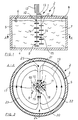
- Fig. 1 is a cross section schematically through a first embodiment of a Stirring device 1 according to the invention for a fermenter 2 of a biogas plant shown in cross section, while Fig. 2 shows a section along the Line A-A of Figure 1.
- the fermenter 2 comprises a cylindrical one Fermenter container 3, a bottom wall 4, a side wall 5 and a top wall 6 has.
- the fermenter container 3 one is here, for example Biomass solids 7 added fermenter liquid 8 added.
- the biomass could also be replaced by a more liquid-like one Material be formed.
- the fermenter container could at least one some have angular cross-section, e.g. B. a square Cross-section.
- the stirring device 1 further comprises a pair of stirrer shafts 9 made of two each other assigned stirrer shafts driven in opposite directions in the operating state 10, 11, which are aligned parallel to each other.
- a common drive 12 for. B. an electric motor provided, the the stirrer shaft 10 drives.
- the stirrer shaft 10 here in the clockwise direction and the stirrer shaft 11 driven counterclockwise. All implementations gas-tight through one of the container walls.
- the two stirrer shafts are each only with an upper stirrer shaft end stored in the area of the bottom wall 4. With her opposite The stirrer shaft ends are self-supporting.
- Stirrer 14 arranged z. B. can be paddles. Between A flow area 15 is provided for both stirrer shafts 10, 11. This Flow-through area 15 is designed here such that the stirrer shafts 10, 11 in the Operation roughly mesh, as is particularly evident from the schematic 1 can be seen.
- the pair of stirrer shafts 9 is here in a central, central fermenter container area arranged approximately vertically.
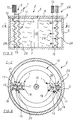
- a fundamentally similar one Structure is shown in FIG. 3, but in which the stirrer shaft pair 9 together with the stirrer shafts 10, 11 eccentrically in the fermenter tank 3 in one is arranged near the side wall.
- the top wall 6 of this fermenter tank 3 is here by means of a central and vertically aligned one Supported center column 16.
- Another difference from the embodiment according to Fig. 1 is that the lower stirrer shaft ends are stored here, and in the area of the bottom wall 4. Otherwise, the structure corresponds that of Fig. 1.
- Fig. 4 is a section along the line B-B of Fig. 3rd shown.
- the agitator shaft pair forms 9 a substantially horizontal, directed circulation flow 19 in total volume of the fermenter tank from (Fig. 2, Fig. 4).
- an overpressure area 20 and Seen in the direction of the circulation flow a vacuum region in front of the stirrer shaft pair 9 as suction area 21, which is based on the flow area 15 and the stirrer shafts 10, 11 between the two stirrer shafts 10, 11 is arranged opposite the overpressure area 20.
- FIGS. 10 to 12 The good and even distribution of the biomass 7 based on the whole Container volume is shown in FIGS. 10 to 12, the different 4 shows an example of the embodiment of FIG 3 and 4 explained.
- Usual fermenter container diameters are in the range of 10 to 20 m, preferably in the range from 13 to 15 m, so that this diameter is very large is compared to the diameter of the stirrer shaft pair 9, the z. B. in the area from about one to two meters. This makes it particularly useful for very large inner diameters of the fermenter container 3 may be required, to provide at least one further pair of stirrer shafts 9, as is shown schematically is shown in Figures 5 and 6, wherein Figure 6 is a schematic Section along the line C-C of Figure 5 shows.
- a second eccentrically arranged stirrer shaft pair 26 is provided, based on the approximately vertical center column 16 the eccentric first stirrer shaft pair 9 is opposite.
- the circulating flow 19 when flowing through the respective flow areas 15 of the agitator shaft pairs 9, 10 after a local intensive there Mix again to distribute the biomass solids 7 throughout Fermenter liquid 8, d. H. in the entire volume of the fermenter tank 3 further promoted in the direction of circulation, so that over the entire Circulation flow path a very good and even distribution of Biomass solids 7 can be achieved in the fermenter liquid 8.
- the second or each further pair of stirrer shafts is thus provided in one area, where the degree of segregation is already so great that a targeted mixing is required.
- Fig. 3 is a schematic and dashed lines lying a pair of stirrer shafts 27 drawn in, which is oriented here approximately horizontally only as an example is arranged eccentrically in the fermenter tank.
- Such a thing horizontally lying pair of agitator shafts 27 can in principle be used alone or but also in combination with several horizontal stirrer shaft pairs or in combination with one or more vertical ones Stirrer shaft pairs depending on the individual requirements and specific Conditions are arranged in the fermenter tank.
- This results in the same results regarding the formation of a local agitator shaft flow 18 and a horizontal circulation flow 19, as before in connection with Figures 1 to 6 has been explained in more detail. in principle it can also be particularly advantageous, e.g. B.
- the stirrers 14 shown only schematically in FIGS. 1 to 4 can to form a possibly desired vertical partial flow, if necessary z. B. be employed at an angle.
- a particularly preferred in this regard Embodiment is shown in Fig. 5, in which the stirrer shaft 9th is formed by two screws as stirrer shafts 10, 11, the screw spiral 28 act as a stirrer, the z. B. depending on the drive direction Auger can also form a superimposed vertical part flow.
- the Screw spiral 28 of the agitator shafts 10, 11 can have a double function at the same time z. B. at least partially as a shredding device, e.g. B.
- stirrer shaft pair 26 is also in connection with the second pair of agitator shafts 26 shown by way of example that for each stirrer shaft of the stirrer shaft pair 26 a separate drive 12 can also be provided, for. B. different To achieve drive speeds of the stirrer shafts.
- FIG. 7 shows, extremely schematically and in principle, that the Stirrer shaft pair 9 also in the interior of the fermenter container 3 can be stored so that this in the longitudinal direction of the stirrer shaft extending pivot axis 30 is pivotable, as is by the Arrow 31 is displayed.
- a definition in the different is advantageous Swivel positions possible.
- flow baffles 32, 33 are also provided by way of example, which in conjunction with a counter clockwise and not here horizontal circulation flow shown a particularly advantageous feed ensure this circulation flow in the suction area 21.
- FIGS. 8 and 9 A further advantageous embodiment variant is shown in FIGS. 8 and 9, in which the stirrer shaft pair 9 can be used as in the fermenter container 3 and removable stirrer shaft module is formed.
- the agitator shaft module a bearing plate 34 which can be inserted into the ceiling wall 6 on which the stirrer shafts 10, 11 with an agitator shaft end are exemplary here are stored immediately.
- the drive 12 is also a component here of the stirrer shaft module, which is arranged here below the bearing plate 34.
- the drive 12 is here, for. B. designed as a hydraulic motor or pneumatic motor, the medium corresponding to a hydraulic fluid in the hydraulic motor or there is air in the pneumatic motor.
- Such a drive by means of a Working medium has an energy line 35, which on the one hand a z.
- Hose line as a supply line 36 for the medium which to a medium compression unit 37, e.g. B. a hydraulic compressor or one Air compressor, is connected and sealed by the bearing plate 34 as Part of the ceiling wall 6 is performed.
- This power line also includes 35 also a z. B. hose line as a discharge line 38 for the medium also sealed from the bearing plate 34 as part of the ceiling wall 6 the fermenter tank 3 is led out.
- the discharge line 38 is in the case of a hydraulic motor as a return line in a closed hydraulic circuit connected to the hydraulic compressor while in the event Blow off a pneumatic motor as a blow-off line into the environment can, as shown in dashed lines in FIG. 8 by the arrow 39.
- the medium compression unit 37 can of course on the bearing plate 34 are stored.
- the entire agitator shaft module then for assembly in the pre-assembled state in the fermenter tank can be used easily and quickly. But it can do just as well removal of the stirrer shaft module for maintenance and / or repair work done quickly and easily, as shown in FIG. 9 is.
Landscapes
- Chemical & Material Sciences (AREA)
- Health & Medical Sciences (AREA)
- Life Sciences & Earth Sciences (AREA)
- Engineering & Computer Science (AREA)
- Chemical Kinetics & Catalysis (AREA)
- Organic Chemistry (AREA)
- Zoology (AREA)
- Wood Science & Technology (AREA)
- Bioinformatics & Cheminformatics (AREA)
- Genetics & Genomics (AREA)
- Biomedical Technology (AREA)
- Biotechnology (AREA)
- Microbiology (AREA)
- Sustainable Development (AREA)
- Molecular Biology (AREA)
- Biochemistry (AREA)
- General Engineering & Computer Science (AREA)
- General Health & Medical Sciences (AREA)
- Oil, Petroleum & Natural Gas (AREA)
- General Chemical & Material Sciences (AREA)
- Processing Of Solid Wastes (AREA)
- Mixers Of The Rotary Stirring Type (AREA)
Abstract
Description
Die Erfindung betrifft eine Rühreinrichtung für einen Fermenter einer Biogasanlage
nach dem Oberbegriff des Anspruchs 1 und ein Verfahren zur Verteilung
von Biomasse in einer Fermenterflüssigkeit mit einer Rühreinrichtung
nach dem Oberbegriff des Anspruchs 21.The invention relates to a stirring device for a fermenter of a biogas plant
according to the preamble of
In Biogasanlagen läuft ein Fermentationsprozess ab, bei dem organische Stoffe, wie beispielsweise Wirtschaftsdünger aus der Landwirtschaft (Rindergülle, Rinder-Festmist, Schweinegülle, Schweine-Festmist, Hühnergülle, Hühner-Trockenkot) und/oder landwirtschaftliche Reststoffe (Grasschnitt-Rübenblätter, Silagen) und/oder Reststoffe aus der Agroindustrie oder verwandten Industrien (Biertreber, Obstreste, Gemüsereste, Rapsschrot, Getreideabputz, Schlempen, Melasse) als Biomasse vergast werden. Die hierbei entstehenden Gase sammeln sich in einem oberen Fermenterbehälterbereich eines Fermenterbehälters und können direkt zur Energieerzeugung verwendet werden, z. B. als Heizgas zur Stromerzeugung in nachgeschalteten Brennkraftmaschinen mit Elektrogeneratoren. Zur Fermentation werden im Fermenterbehälter die organischen Stoffe mit Flüssigkeit versetzt und Mikroorganismen, wie z. B. Hefen, Bakterien, etc. zugeführt, so dass der Fermentations- bzw. der Vergasungsprozess unter aeroben oder anaeroben Bedingungen ablaufen kann. A fermentation process takes place in biogas plants, in which organic Substances such as manure from agriculture (cattle manure, Cattle solid manure, pig manure, pig solid manure, chicken manure, chicken dry manure) and / or agricultural residues (cut grass beet leaves, Silages) and / or residues from the agro-industry or related Industries (beer spent grains, fruit leftovers, vegetable leftovers, rapeseed meal, grain cleaning, Stillage, molasses) are gasified as biomass. The resulting Gases collect in an upper fermenter container area of a fermenter container and can be used directly for power generation z. B. as heating gas for power generation in downstream internal combustion engines with electrical generators. For fermentation are in the fermenter tank the organic substances are mixed with liquid and microorganisms such. B. Yeasts, bacteria, etc. supplied, so that the fermentation or the gasification process can occur under aerobic or anaerobic conditions.
Ein Problem bei derartigen allgemein bekannten Fermentationsprozessen ist, dass die Biomasse, insbesondere Biomasse-Feststoffe in der Fermenterflüssigkeit regelmäßig nicht gleichmäßig verteilt sind, da sie z. B. aufschwimmen und sich im Bereich der Flüssigkeitsoberfläche ansammeln, was z. B. der Fall ist, wenn das spezifische Gewicht der Biomasse geringer ist als dasjenige der Fermenterflüssigkeit, z. B. Wasser. Andererseits kann aber auch das Problem bestehen, dass Biomasse, insbesondere Biomasse-Feststoffe mit einem höheren spezifischen Gewicht als die Fermenterflüssigkeit auf den Fermenterbehälterboden absinken und sich dort als Sinkschichten ansammeln. Auch eine derartige Ansammlung von Biomasse bewirkt eine ungleichmäßige Biomasseverteilung in der Fermenterflüssigkeit, was sich insgesamt nachteilig auf den Wirkungsgrad des Fermentationsprozesses auswirkt.One problem with such well known fermentation processes is that the biomass, especially biomass solids in the fermenter liquid are regularly not evenly distributed since they are e.g. B. float up and accumulate in the area of the liquid surface, which z. B. the case is when the specific weight of the biomass is less than that Fermenter liquid, e.g. B. water. On the other hand, the problem can also arise exist that biomass, especially biomass solids with a higher specific weight as the fermenter liquid on the bottom of the fermenter tank sink and collect there as sink layers. Also one such accumulation of biomass causes an uneven distribution of biomass in the fermenter liquid, which affects the overall disadvantage Affects the efficiency of the fermentation process.
Für eine Verteilung der Biomasse in der Fermenterflüssigkeit sind bereits Tauchmotorrührgeräte als Rühreinrichtungen bekannt, die mittels einer Seilwinde entlang eines Aggregatträgers verfahrbar sind. So ist aus der gattungsgemäßen DE 197 32 168 C1 eine Rühreinrichtung für einen Fermenter einer Biogasanlage mit einer Rührerwelle bekannt, die wenigstens einen Rührer aufweist, wobei die Rührerwelle mittels einem Rührerwellenantrieb antreibbar ist und wobei die Rührerwelle in eine in einem Fermenterbehälterinnenraum aufnehmbare und mit Biomasse versetzte Fermenterflüssigkeit eintauchbar ist zum Umwälzen der Fermenterflüssigkeit zur Verteilung der Biomasse in der Fermenterflüssigkeit.For a distribution of the biomass in the fermenter liquid are already Submersible mixers known as stirring devices, which are operated by means of a winch are movable along an assembly carrier. So is from the generic DE 197 32 168 C1 a stirring device for a fermenter Biogas plant with a stirrer shaft known, the at least one stirrer has, the stirrer shaft being drivable by means of a stirrer shaft drive is and wherein the stirrer shaft in a inside a fermenter absorbable fermenter liquid mixed with biomass is immersible to circulate the fermenter liquid to distribute the biomass in the Fermenter liquid.
Konkret ist die Rühreinrichtung hier durch ein Tauchmotorrührgerät gebildet, das an einem vertikal im Behälter angeordneten Aggregatträger höhenverstellbar gehalten ist. Eine Seiltrommel ist hier innerhalb im oberen Bereich des Fermenterbehälters angeordnet, so dass keine gasdichte Seildurchführung durch eine Fermenterbehälterwand erforderlich ist. Eine außerhalb des Behälters angeordnete Betätigungseinrichtung für den Seiltrommelantrieb ist mit dem mittels einer dichten Durchführung durch eine Behälterwand geführten Seiltrommelantrieb verbunden. Das Tauchmotorrührgerät wird hier durch einen Tauchmotor gebildet, der eine herkömmliche Rührerwelle mit einem Propellerrührer antreibt. Eine derartige Rühreinrichtung mit einem an einer Rührerwelle angeordneten Propellerrührer führt nur zu einer Vermischung der Biomasse und der Fermenterflüssigkeit in einem lokal begrenzten Bereich innerhalb der Fermenterflüssigkeit. Um in unterschiedlichen Fermenterflüssigkeitsbereichen eine Durchmischung zu erreichen, ist das Tauchmotorrührgerät mittels dem Aggregatträger um dessen Längsachse zu verschwenken, damit die Rührerwelle mitsamt Propellerrührer auch andere bezüglich der Biomasseansammlungen kritische Fermenterflüssigkeitsbereiche durchmischt. Hierzu sind insbesondere im Hinblick auf die Seiltrommelanordnung komplizierte Getriebemechaniken und/oder Gelenkanordnungen erforderlich, um das Verschwenken des Tauchmotorrührgerätes um den Aggregatträger zu ermöglichen. Jedoch ergibt sich auch hier wiederum das Problem, dass auch im verschwenkten Zustand dann nur eine Vermischung in diesem begrenzten Bereich innerhalb der Fermenterflüssigkeit einstellt. Insbesondere in rührerwellenfernen Fermenterflüssigkeitsbereichen ergibt sich regelmäßig eine Entmischung zwischen der Biomasse und der Fermenterflüssigkeit, d. h. es kommt zu einer unerwünschten Phasentrennung und damit zur erneuten Ausbildung von unerwünschten Schwimm- oder Sinkschichten. Dies beruht insbesondere auch darauf, dass die Abmessungen der Fermenterbehälter, insbesondere deren Innendurchmesser regelmäßig sehr groß gegenüber den Abmessungen der Rührerwellen mitsamt Propellerrührer ist. So liegen beispielsweise die Fermenterbehälterdurchmesser zwischen 13-15 m, während eine Rührerwelle relativ klein, z. B. im Bereich von 0,5 m, ausgebildet ist. Insgesamt wird somit trotz des Einsatzes derartiger Tauchmotorrührgeräte aufgrund der nach wie vor gegebenen ungleichmäßigen Biomasseverteilung bezogen auf die gesamte Fermenterflüssigkeit der Wirkungsgrad des Fermentationsprozesses nur unwesentlich erhöht. Specifically, the stirring device is formed here by a submersible mixer, the height adjustable on a unit carrier arranged vertically in the container is held. A rope drum is here in the upper area of the Fermenter container arranged so that no gas-tight cable duct through a fermenter tank wall is required. One outside the container arranged actuator for the cable drum drive is with the one led through a container wall by means of a sealed bushing Cable drum drive connected. The submersible mixer is here by a Submersible motor formed a conventional stirrer shaft with a propeller stirrer drives. Such a stirring device with a stirrer shaft arranged propeller stirrer only leads to a mixing of the biomass and the fermenter liquid in a localized area within the Fermenter liquid. To in different fermenter liquid areas To achieve a thorough mixing, the submersible mixer is by means of the Swivel the unit carrier around its longitudinal axis, so that the stirrer shaft together with propeller stirrers also regarding biomass accumulations critical fermenter liquid areas mixed. This is particularly true complicated gear mechanisms with regard to the cable drum arrangement and / or hinge assemblies required to pivot of the submersible mixer to enable the unit carrier. however Here again the problem arises that even in the pivoted state then just a mix in that limited area within the Sets fermenter liquid. Especially in fermenter liquid areas remote from the stirrer shaft there is regular segregation between the Biomass and the fermenter liquid, d. H. there is an undesirable Phase separation and thus for the re-formation of undesired Floating or sinking layers. This is particularly due to the fact that the dimensions of the fermenter containers, in particular their inner diameter regularly very large compared to the dimensions of the stirrer shafts with propeller stirrer. For example, the diameter of the fermenter tank between 13-15 m, while a stirrer shaft is relatively small, e.g. B. is formed in the range of 0.5 m. Overall, despite the stake such submersible mixers due to the still uneven Biomass distribution based on the total fermenter liquid the efficiency of the fermentation process increases only slightly.
Aus Explosionsschutzgründen ist zudem die Anwesenheit von elektrischen Leitungen im eine Gasphase aufweisenden Fermenterbehälterinnenraum problematisch, da dies aus sicherheitstechnischen Gründen eine dauerhafte, zeitaufwendige Kontrolle der Anlage erfordert.For explosion protection reasons, the presence of electrical Pipes in the interior of the fermenter tank having a gas phase problematic because this is a permanent time-consuming control of the system required.
Aufgabe der Erfindung ist es daher, eine Rühreinrichtung für einen Fermenter einer Biogasanlage sowie ein Verfahren zur Verteilung von Biomasse in einer Fermenterflüssigkeit mit einer Rühreinrichtung zu schaffen, die bei relativ einfachem Aufbau eine möglichst gleichmäßige Verteilung der Biomasse in der gesamten Fermenterflüssigkeit zur Vermeidung von Biomasse-Schwimmschichten und/oder Biomasse-Sinkschichten und daher eine Erhöhung des Wirkungsgrades des gesamten Fermentationsprozesses ermöglichen.The object of the invention is therefore a stirring device for a fermenter a biogas plant and a method for distributing biomass in one To create fermenter liquid with a stirrer that is relatively simple Establish a distribution of the biomass in the entire fermenter liquid to avoid biomass floating layers and / or biomass sink layers and therefore an increase in Enable efficiency of the entire fermentation process.
Diese Aufgabe wird bezüglich der Rühreinrichtung gelöst mit den Merkmalen
des Anspruchs 1.This task is solved with the features with the stirring device
of
Gemäß Anspruch 1 sind zwei einander zugeordnete und im Betriebszustand
gegensinnig angetriebene Rührerwellen als Rührerwellenpaar vorgesehen, die
in etwa parallel zueinander ausgerichtet sind und die im in die Fermenterflüssigkeit
eingetauchten, angetriebenen Zustand eine lokale, im Wesentlichen
turbulente Rührerwellenströmung um die jeweilige Rührerwelle herum ausbilden
für eine intensive lokale Vermischung der Biomasse mit der Fermenterflüssigkeit
im rührerwellenpaarnahen Fermenterflüssigkeitsbereich. Ferner
bilden die in die Fermenterflüssigkeit eingetauchten Rührerwellen im angetriebenen
Zustand eine im Wesentlichen horizontale, gerichtete Umwälzströmung
im gesamten Volumen des Fermenterbehälters aus dergestalt, dass die im
Wesentlichen horizontale Umwälzströmung nach Durchströmen eines Durchströmbereiches
zwischen den beiden Rührerwellen von einem im Bereich der
Rührerwellen ausgebildeten Überdruckbereich ausgehend in den rührerwellenpaarfernen
Fermenterflüssigkeitsbereich wegströmt und anschließend wieder
im Kreislauf zu einem Unterdruckbereich als Ansaugbereich im Bereich der
Rührerwellen zurückströmt.According to
Vorteilhaft wird mit einem derartigen Aufbau der Rühreinrichtung mit wenigstens einem Rührerwellenpaar eine sehr intensive lokale Durchmischung der Biomasse mit der Fermenterflüssigkeit im rührerwellenpaarnahen Flüssigkeitsbereich erzielt, so dass die Biomasse in diesem lokalen Bereich in optimaler Weise besonders gleichmäßig in der Fermenterflüssigkeit verteilt ist, wie dies für einen hohen Wirkungsgrad des Fermentationsprozesses insgesamt wünschenswert ist. Durch die im Wesentlichen überlagerte horizontale, gerichtete Umwälzströmung wird hier vorteilhaft zusätzlich die gleichmäßige Verteilung der Biomasse im gesamten Restvolumen des Fermenterbehälters erreicht, d. h. auch in dem rührerwellenpaarfernen Fermenterflüssigkeitsbereich erzielt, da die im Bereich der Rührerwellen durchmischten Fermenterflüssigkeitsbereiche mittels der Umwälzströmung weiterverteilt werden, um die möglichst gleichmäßige Verteilung der Biomasse im gesamten Volumen des Fermenterbehälters zu erzielen.Such a construction of the stirring device is advantageous with at least a very intensive local mixing of the stirrer shaft pair Biomass with the fermenter liquid in the liquid area near the stirrer shaft achieved so that the biomass in this local area in optimal Way is particularly evenly distributed in the fermenter liquid, like this desirable for a high efficiency of the fermentation process as a whole is. Due to the essentially superimposed horizontal, directional Circulation flow is also advantageous here the even distribution the biomass in the entire remaining volume of the fermenter tank is reached, d. H. also achieved in the fermenter liquid area remote from the stirrer shaft pair, since the fermenter liquid areas mixed in the area of the stirrer shafts be redistributed by means of the circulating flow in order to achieve the Even distribution of the biomass in the entire volume of the fermenter tank to achieve.
D. h., dass für den Fall, dass sich Sinkschichten und/oder Schwimmschichten in der Fermenterflüssigkeit ausbilden, die z. B. durch Biomasse-Feststoffe gebildet sind, somit durch die lokale und im Wesentlichen turbulente Rührerwellenströmung eine sehr gute und gleichmäßige Verteilung der einzelnen Biomasse-Feststoffe im gesamten rührerwellenpaarnahen Fermenterflüssigkeitsbereich erzielt wird, d. h., dass die Sinkschichten und/oder Schwimmschichten im Wesentlichen aufgelöst werden. Um auch in dem rührerwellenpaarfernen Fermenterflüssigkeitsbereich eine möglichst gleichmäßige Verteilung der Biomasse-Feststoffe in der Fermenterflüssigkeit zu erzielen, wird mit den Rührerwellen gleichzeitig die im Wesentlichen horizontale, gerichtete Umwälzströmung im gesamten Volumen des Fermenterbehälters ausgebildet, wodurch ausgehend vom lokalen Rührerwellenbereich die eine gleichmäßige Biomasse-Verteilung aufweisenden Fermenterflüssigkeitsteile sozusagen mit der Umwälzströmung auf die Reise geschickt werden, wobei durch die im Kreislauf geführte Umwälzströmung die gleichmäßige Verteilung der Biomasse in der gesamten Fermenterflüssigkeit sichergestellt wird. Sobald es im Verlauf des Umwälzströmungsweges zu einer gewissen Entmischung zwischen der Biomasse und der Fermenterflüssigkeit kommt, werden diese vom Ansaugbereich des Rührerwellenpaares wieder angesaugt und im Bereich der Rührerwellen wieder in der zuvor beschriebenen Art und Weise vermischt, bevor sie wieder in Umwälzströmungsrichtung mit sehr gleichmäßiger Verteilung weiterbefördert werden. Dadurch können Sinkschichten und/oder Schwimmschichten aus Biomasse, insbesondere aus Biomasse-Feststoffen in Fermenterbehältern vorteilhaft sehr gut vermieden werden. Dies insbesondere im Hinblick auf Biogasanlagen, bei denen der Fermenterbehälterdurchmesser in der Größenordnung von 10-20 m, z. B. in der Größenordnung von 13-15 m, liegt und die Rührerwellenanordnung z. B. eine Breite von 1-2 m aufweist, d. h. also der Fermenterbehälter sehr groß gegenüber den Rührerwellen ist.That is, in the event that there are sink layers and / or floating layers form in the fermenter liquid, the z. B. formed by biomass solids are, therefore, by the local and essentially turbulent agitator shaft flow a very good and even distribution of the individual biomass solids in the entire fermenter liquid area close to the stirrer shaft is achieved, d. that is, the sink layers and / or floating layers essentially be resolved. To also in the pair of stirrer shafts Distribution of the biomass solids as evenly as possible To achieve in the fermenter liquid is using the stirrer shafts at the same time the essentially horizontal, directed circulation flow formed in the entire volume of the fermenter tank, whereby based on the local agitator shaft area, the even distribution of biomass having fermenter liquid parts with the circulating flow, so to speak be sent on the trip, being through the cycle guided circulation flow the even distribution of the biomass in the entire fermenter liquid is ensured. Once in the course of Circulation flow path to a certain separation between the biomass and the fermenter liquid comes from the suction area of the pair of stirrer shafts sucked in again and in the area of the stirrer shafts again mixed in the way described before before again conveyed in the direction of the circulation flow with a very uniform distribution become. This can sink layers and / or floating layers Biomass, especially from biomass solids in fermenter tanks advantageously be avoided very well. This especially with regard to biogas plants, where the fermenter tank diameter is of the order of magnitude from 10-20 m, e.g. B. in the order of 13-15 m, and the stirrer shaft arrangement z. B. has a width of 1-2 m, d. H. so the fermenter tank is very large compared to the stirrer shafts.
Mit den Merkmalen der Ansprüche 2 und 3 werden Rühreinrichtungen beansprucht,
mit denen vorteilhaft unterschiedliche Arten von Umwälzströmungen
in der Fermenterflüssigkeit eingestellt werden können, z. B. eine Umwälzströmung,
die sich nach dem Wegströmen vom Überdruckbereich in zwei entgegengesetzte
horizontale Umwälzteilströmungen aufteilt. Ebenso ist aber auch
eine Anordnung der Rührerwellen als Rührerpaar dergestalt möglich, dass sich
im Wesentlichen eine einzige gleichgerichtete Haupt-Umwälzströmung in der
Fermenterbehälterflüssigkeit einstellt. Mit derartigen Aufbauten der Rührereinrichtung
kann eine vorteilhafte und einfache Anpassung der jeweils benötigten
Umwälzströmung an die jeweils gegebenen Fermentationsverhältnisse für eine
optimale Verteilung der Biomasse in der Fermenterflüssigkeit gewählt werden.
Insbesondere mit einer in etwa senkrecht im Fermenterbehälter angeordneten
Mittelsäule, die regelmäßig eine Abstütz- und Tragfunktion für eine Behälterdecke,
z. B. eine Behälterbetondecke, übernimmt, kann bei einer exzentrischen
Anordnung des Rührerwellenpaars eine vorteilhafte Umwälzströmung in
Radialrichtung um die Mittelsäule herum für eine besonders vorteilhafte
gleichmäßige Verteilung der Biomasse, insbesondere von Biomasse-Feststoffen
in der Fermenterflüssigkeit erzielt werden.With the features of
Nach Anspruch 4 können dabei die Rührerwellen grundsätzlich bezogen auf
den Fermenterbehälter in etwa senkrecht oder waagrecht ausgerichtet in die
Fermenterbehälterflüssigkeit eingetaucht werden. Diese erhöht die Flexibilität
beim Einsatz der Rührerwellen als vorteilhafte Rührereinrichtung zur Ausbildung
erwünschter Strömungsverhältnisse.According to
Insbesondere für den Fall, dass die Fermenterbehälterdurchmesser sehr groß
gegenüber den Rührerwellenabmessungen und/oder im Verlauf des Umwälzströmungsweges
zwischen dem Überdruckbereich und dem Ansaugbereich
eine zu große Entmischung zwischen Biomasse und Fermenterflüssigkeit
stattfinden würde, kann gemäß Anspruch 5 vorgesehen sein, dass in Umwälzströmungsrichtung
gesehen beabstandet zum ersten Rührerwellenpaar wenigstens
ein weiteres Rührerwellenpaar vorgesehen ist. Ein derartiger Aufbau
ist besonders bevorzugt in Verbindung mit großen Fermenterbehälterdurchmessern,
die regelmäßig auch eine Mittelsäule aufweisen, bei der ein erstes
exzentrisches Rührerwellenpaar bezogen auf die in etwa senkrechte Mittelsäule
in etwa gegenüberliegend zu einem zweiten exzentrischen Rührerwellenpaar
angeordnet ist. Die Rührerwellenpaare werden hier jeweils so angetrieben,
dass die Umwälzströmung beim Durchströmen des Durchströmbereichs
des jeweiligen Rührerwellenpaares nach einer dortigen lokalen intensiven
Durchmischung wieder zur Verteilung der Biomasse in der gesamten Fermenterflüssigkeit
in Umwälzströmungsrichtung weiterförderbar ist. Je nach
Größe und konkretem Aufbau des Fermenterbehälters können ggf. aber auch
mehr als zwei Rührerwellenpaare vorgesehen sein. Ein Kriterium für den Einsatz
mehrerer Rührerwellenpaare ist somit insbesondere der jeweilige zwischen
den einzelnen Rührerwellenpaaren zurückgelegte Umwälzströmungsweg
und der jeweilige Grad der Entmischung der Biomasse mit der Fermenterflüssigkeit.Especially in the event that the fermenter container diameter is very large
compared to the stirrer shaft dimensions and / or in the course of the circulation flow path
between the overpressure area and the suction area
excessive segregation between biomass and fermenter liquid
would take place, it can be provided according to
Insbesondere zur Veränderung und/oder Beeinflussung der Umwälzströmungsrichtung
kann nach Anspruch 6 vorgesehen sein, dass das Rührerwellenpaar
so im Fermenterbehälterinnenraum lagerbar ist, dass dieses um eine
in Rührerwellenlängsrichtung verlaufende Schwenkachse verschwenkbar sind.
Dabei ist vorzugsweise eine Festlegung in unterschiedlichen Schwenkpositionen
vorgesehen.In particular for changing and / or influencing the direction of the circulation flow
can be provided according to
Nach Anspruch 7 ist für ein Rührerwellenpaar ein gemeinsamer Antrieb für
beide Rührerwellen vorgesehen, wobei der Antrieb eine der Rührerwellen antreibt
und ferner Mittel vorgesehen sind, mit denen eine Antriebskraft auf die
jeweils andere Rührerwelle übertragbar ist. Derartige Mittel können z. B. ein
Zahnriemen in Verbindung mit einer Zahnradanordnung zur Drehrichtungsumkehr
zur Ausbildung einer gegensinnigen Antriebsrichtung der Rührerwellen
eines Rührerpaares sein. Grundsätzlich besteht jedoch auch die Möglichkeit,
dass für jede Rührerwelle eines Rührerwellenpaars ein separater Antrieb vorgesehen
wird. Ferner können die Rührerwellen je nach gewünschter Richtung
der Umwälzströmung in eine Vorwärts- und/oder Rückwärtsrichtung jeweils
gegensinnig angetrieben werden bzw. können auch die einzelnen Rührerwellen
eines Rührerwellenpaars in Verbindung mit einem gegensinnigen Antrieb
unterschiedliche Antriebsgeschwindigkeiten aufweisen, was z. B. bei unterschiedlich
ausgebildeten Rührerwellen erforderlich sein kann. Dies ist durch
eine entsprechende Umsetzung oder Übersetzung auch bei einem einzigen
gemeinsamen Antrieb für beide Rührerwellen besonders einfach realisierbar.
Damit ist eine optimale Anpassung an die jeweils konkret gegebenen Bedingungen
in Verbindung mit einer Biogasanlage und einem Fermenterbehälter
möglich. According to
Grundsätzlich kann der Antrieb, z. B. ein Elektromotor mit variabler Drehzahlsteuerung,
nach Anspruch 8 außerhalb des Fermenterbehälters angeordnet
sein. Hierzu ist z. B. dann lediglich ein Antriebsstrang der Rührerwelle dicht
durch eine Behälterwand zu führen, z. B. durch eine obere Behälterwand als
Behälterdecke, was einfach zu bewerkstelligen ist. Besonders bevorzugt ist
jedoch ein Aufbau gemäß Anspruch 9, bei dem der wenigstens eine Antrieb im
Fermenterbehälter angeordnet und mittels einem Arbeitsmedium antreibbar ist.
Dieser mittels einem Arbeitsmedium antreibbare Antrieb ist mit einer Energieleitung
verbunden, die einerseits eine Rohr- und/oder Schlauchleitung als Zuführleitung
für das Medium aufweist, die an einer Medium-Kompressionseinheit
angeschlossen ist und die dicht durch eine Behälterwand zum Antrieb geführt
ist. Weiter umfasst die Energieleitung eine Rohr- und/oder Schlauchleitung als
Abführleitung für das Medium, die dicht durch eine Behälterwand aus dem
Fermenterbehälter herausgeführt ist. Die Medium-Kompressionseinheit kann
dann vorzugsweise elektrisch betrieben und außerhalb des Fermenterbehälters
angeordnet werden.Basically, the drive, e.g. B. an electric motor with variable speed control,
arranged outside of the fermenter tank according to claim 8
his. For this purpose, e.g. B. then only a drive train of the stirrer shaft is sealed
to lead through a container wall, e.g. B. by an upper container wall as
Container ceiling, which is easy to do. Is particularly preferred
however, a structure according to
Gemäß einer ersten konkreten Ausführungsform nach Anspruch 10 kann der
Antrieb ein Hydraulik-Motor sein, wobei das Medium eine Hydraulikflüssigkeit
und die Kompressionseinheit ein Hydraulik-Kompressor ist. Die Abführleitung
ist dabei als Rückleitung in einem geschlossenen Kreislauf an den Hydraulik-Kompressor
angeschlossen. Alternativ dazu kann nach Anspruch 11 der Antrieb
auch durch einen Pneumatik-Motor gebildet sein, wobei als Arbeitsmedium
hier dann Luft verwendet ist und die Kompressionseinheit als Luftkompressor
ausgebildet ist. Bei dieser Anordnung reicht es aus, wenn die Abführleitung
als Abgasleitung lediglich dicht aus dem Fermenterbehälter geführt ist.
Bei Verwendung eines anderen Gases, beispielsweise eines Inertgases, kann
auch hier ein geschlossener Gaskreislauf mit einer Gasrückführung zum Luftkompressor
eingesetzt werden. Sowohl in der Hydraulik- als auch in der
Pneumatikausführung ergeben sich die Vorteile, dass die elektrisch betriebenen
Kompressoren außerhalb des Fermenterbehälters angeordnet sind und
somit der insbesondere aufgrund der Gasphase erforderliche Explosionsschutz
die Verwendung von Hydraulik- oder Gasleitungen sowie die entsprechenden
Hydraulik- oder Gasmotoren einfach beherrschbar ist. Gegenüber einer elektrischen
Energieversorgung mit Elektrokabeln ist zumindest im Fermenterbehälter
ein Zwei-Leitungssystem mit Rohr- und/oder Schlauchleitungen als Medium-Zuführleitung
und Medium-Abführleitung erforderlich. Insbesondere bei
Verwendung eines Pneumatik-Motors ist ein sonst übliches Abblasen von Luft
unmittelbar am Motor nicht möglich, da diese Luft in den Flüssigkeitsbereich
und dann in den Bereich der Gasphase gelangen würde und dort zu einer unerwünschten
Verdünnung des Biogases und einer Gasvermehrung führen
würde.According to a first concrete embodiment according to
Die Merkmale des Anspruchs 12 wurden bereits zuvor in Verbindung mit den
Merkmalen des Anspruchs 7 gewürdigt, so dass hier nicht mehr näher darauf
eingegangen wird.The features of
Nach Anspruch 13 ist der Durchströmbereich zwischen den Rührerwellen eines
Rührerwellenpaares so ausgebildet, dass die Rührerwellen mitsamt ihrer
Rührer entweder einen Spaltabstand voneinander aufweisen oder dass die
Rührerwellen mitsamt ihrer Rührer im Betrieb wenigstens teilweise ineinandergreifen.
Dies hängt von der jeweiligen konkreten Ausgestaltung der Rührerwellen
ab ebenso wie von den Bedingungen im Fermenterbehälter, z. B. den
Durchmessergrößen oder aber auch den Anforderungen an den Ansaugbereich
und den Überdruckbereich.According to
Grundsätzlich können die Rührerwellen mit beiden Rührerwellenenden im Bereich
der Behälterwände eines Fermenterbehälters gelagert werden, wodurch
sich insbesondere eine stabile und sichere Anordnung der Rührerwellen im
Fermenterbehälter im montierten Zustand ergibt. Gemäß einer besonderen
Ausführungsform nach Anspruch 14 können die Rührerwellen jedoch auch lediglich
mit einem Rührerwellenende im Bereich der Behälterwand mittelbar
oder unmittelbar gelagert sein, so dass das andere gegenüberliegende Rührerwellenende
freitragend, d. h. nicht gelagert ist. Ein derartiger Aufbau kann
z. B. dann von Vorteil sein, wenn eine gewisse Ausweichbarkeit, d. h. Verlagerung
der Rührerwellen insbesondere im Hinblick auf durch den Durchströmbereich
hindurchgepresste große sperrige Biomasse-Feststoffe erforderlich ist,
da hierdurch dann die Funktionsfähigkeit weiterhin erhalten wird ohne eine gegebenenfalls
erfolgende Beschädigung der Rührerwellenanordnung.Basically, the stirrer shafts with both stirrer shaft ends in the area
the tank walls of a fermenter tank are stored, whereby
a stable and safe arrangement of the stirrer shafts in particular
Fermenter container in the assembled state results. According to a special one
Embodiment according to
Gemäß einer besonders bevorzugten Ausgestaltung nach Anspruch 15 ist das
Rührerwellenpaar jeweils als in den Fermenterbehälter einsetzbares und
herausnehmbares Rührerwellenmodul ausgebildet. Besonders bevorzugt weist
dabei das Rührerwellenmodul nach Anspruch 16 eine in die Behälterwand einsetzbare
Lagerplatte auf, an der die Rührerwellen mit einem Rührerwellenende
mittelbar oder unmittelbar gelagert sind. Vorzugsweise ist auch der wenigstens
eine Antrieb Bestandteil des Rührerwellenmoduls und je nach Ausführungsart
des Antriebs bezogen auf den montierten Zustand des Rührerwellenmoduls
wenigstens zum Teil oberhalb oder unterhalb an der Lagerplatte angeordnet.
So kann beispielsweise bei einem Hydraulik- oder Pneumatikmotor der Antrieb
an der Unterseite der Lagerplatte angeordnet sein, während ein Elektromotor
aus Explosionsschutzgründen auf der Oberseite der Lagerplatte montiert sein
müsste. Ein derartiges Modul kann z. B. mittels einem Hebezeug, z. B. einem
Kran, auf einfache Weise komplett fertig montiert als Vormontagemodul in einen
Fermenterbehälter eingesetzt werden, so dass hierdurch die Montagearbeiten
auf der Biogasanlagenbaustelle selbst reduziert werden können. Zudem
ist ein derartiger Aufbau mit dem Hebezeug auch auf besonders einfache
Weise sehr schnell herausnehmbar, z. B. im Falle einer erforderlichen Wartung
und/oder Reparatur an einem Modulbestandteil. Ein derartiges Modul kann besonders
einfach und schnell im jeweiligen Fertigungsbetrieb vormontiert werden,
was grundsätzlich für eine Vielzahl von Modulen wünschenswert ist, da
sich hierdurch ein größerer Grad der Automatisierung ergibt. According to a particularly preferred embodiment according to
Nach Anspruch 17 ist im Strömungsbereich der Umwälzströmung wenigstens
ein Strömungsleitblech, vorzugsweise zum Leiten der Strömung in Richtung
zum Ansaugbereich des Rührerwellenpaars hin, und/oder wenigstens ein
Strömungsbrecher, vorzugweise zum Ausbilden einer Vertikalströmungskomponente,
vorgesehen. Dadurch lässt sich die jeweils gewünschte Umwälzströmung
je nach den individuellen Erfordernissen und Wünschen auf einfache
und preiswerte Weise einstellen.According to
Gemäß einer besonders bevorzugten Ausgestaltung nach Anspruch 18 ist wenigstens
eine der Rührerwellen durch eine Schnecke mit Schneckenwendel als
Rührer gegebenenfalls zur Ausbildung einer zusätzlichen, überlagerten Vertikalteilströmung
gebildet. Die Schnecke kann dabei als seelenlose Schnecke
oder aber auch als Bandschnecke ausgebildet sein. Insbesondere für den
nach Anspruch 19 bevorzugten Anwendungsfall, dass die Schneckenwendel
der Rührerwellen jedes Rührerwellenpaars in einer Doppelfunktion wenigstens
teilweise als Zerkleinerungseinrichtung für die in den Durchströmbereich gelangende
Biomasse ausgebildet ist, können z. B. an den Schneckenwendelaußenseiten
auch Schlagkanten, z. B. durch Aufschweißungen, vorgesehen sein.
Eine derartige Doppelfunktion ist besonders vorteilhaft, da hierdurch auch größere
Biomasse-Feststoffe, z. B. Äste, Zweige oder dergleichen vorteilhaft zerkleinert
werden können, was sich insgesamt positiv auf den Wirkungsgrad des
Fermentationsprozesses auswirkt. Die die Rührer bildenden Schneckenwendel
können dabei je nach Antriebsrichtung der jeweiligen durch eine Schnecke gebildeten
Rührerwelle eine zusätzliche Vertikalströmungskomponente ausbilden,
was sich wiederum besonders vorteilhaft auf die gleichmäßige Verteilung
der einzelnen z. B. Biomasse-Feststoffe in der gesamten Fermenterflüssigkeit
zur Vermeidung von Sinkschichten und/oder Schwimmschichten auswirkt.According to a particularly preferred embodiment according to
Alternativ dazu ist nach Anspruch 20 vorgesehen, dass wenigstens eine der Rührerwellen dort angebrachte, vorzugsweise dort angeschweißte Paddel und/oder Balken und/oder Scheiben und/oder Propeller und/oder Gitter als Rührer aufweist, die gegebenenfalls auch so angestellt sein können, dass sich eine zusätzliche, überlagerte Vertikalströmungskomponente ausbildet. Beispielsweise können die einzelnen Rührerelemente hierzu schräg angestellt werden.Alternatively, it is provided according to claim 20 that at least one of the Paddles attached, preferably welded there, to stirrer shafts and / or beams and / or disks and / or propellers and / or grids as Has stirrers, which may also be employed in such a way that forms an additional, superimposed vertical flow component. For example the individual stirrer elements can be set at an angle become.
Die Erfindung wird bezüglich des Verfahrens mit den Merkmalen des Anspruchs
21 gelöst.The invention relates to the method having the features of the
Die sich hierdurch ergebenden Vorteile und dieselben wie sie bereits zuvor in Verbindung mit der Rühreinrichtung erläutert wurden.The resulting benefits and the same as those previously discussed in Connection with the stirring device have been explained.
Die Erfindung wird nachfolgend anhand einer Zeichnung näher erläutert.The invention is explained in more detail with reference to a drawing.
Es zeigen:
- Fig. 1
- einen schematischen Querschnitt als Prinzipskizze durch eine erfindungsgemäße Rühreinrichtung für einen Fermenter einer Biogasanlage,
- Fig. 2
- einen schematischen Schnitt entlang der Linie A-A der Fig. 1,
- Fig. 3
- einen schematischen Querschnitt durch eine alternative Ausführungsform einer erfindungsgemäßen Rühreinrichtung für einen Fermenter einer Biogasanlage,
- Fig. 4
- einen schematischen Schnitt entlang der Linie B-B der Fig. 3,
- Fig. 5
- einen schematischen Querschnitt durch eine weitere alternative Ausführungsform einer erfindungsgemäßen Rühreinrichtung für einen Fermenter einer Biogasanlage,
- Fig. 6
- eine schematische Schnittansicht entlang der Linie C-C der Fig. 5,
- Fig. 7
- einen schematischen Querschnitt durch einen Fermenterbehälter mit verschwenkbarem Rührerwellenpaar,
- Fig. 8
- einen schematischen Querschnitt durch eine erfindungsgemäße Rühreinrichtung für einen Fermenter einer Biogasanlage, bei der die Rühreinrichtung als Modul ausgebildet ist, im montierten Zustand,
- Fig. 9
- einen schematischen Querschnitt entsprechend Fig. 8 mit teilweise herausgenommenem Modul,
- Fig. 10
- einen schematischen Querschnitt entlang der Linie Z-Z1 der Fig. 4 zur beispielhaften Darstellung des Verteilungsgrades von Biomasse in der Fermenterflüssigkeit,
- Fig. 11
- einen schematischen Querschnitt entlang der Linie Z-Z2 der Fig. 4 zur beispielhaften Darstellung des Verteilungsgrades von Biomasse in der Fermenterflüssigkeit, und
- Fig. 12
- einen schematischen Querschnitt entlang der Linie Z-Z3 der Fig. 4 zur beispielhaften Darstellung des Verteilungsgrades von Biomasse in der Fermenterflüssigkeit.
- Fig. 1
- 1 shows a schematic cross section as a basic sketch through an inventive stirring device for a fermenter of a biogas plant,
- Fig. 2
- 2 shows a schematic section along the line AA in FIG. 1,
- Fig. 3
- 2 shows a schematic cross section through an alternative embodiment of a stirring device according to the invention for a fermenter of a biogas plant,
- Fig. 4
- 3 shows a schematic section along the line BB in FIG. 3,
- Fig. 5
- 2 shows a schematic cross section through a further alternative embodiment of a stirring device according to the invention for a fermenter of a biogas plant,
- Fig. 6
- 5 shows a schematic sectional view along the line CC of FIG. 5,
- Fig. 7
- 1 shows a schematic cross section through a fermenter tank with a pivotable pair of stirrer shafts,
- Fig. 8
- 2 shows a schematic cross section through a stirring device according to the invention for a fermenter of a biogas plant, in which the stirring device is designed as a module, in the assembled state,
- Fig. 9
- 8 shows a schematic cross section corresponding to FIG. 8 with the module partially removed,
- Fig. 10
- 4 shows a schematic cross section along the line Z-Z1 of FIG. 4 for the exemplary representation of the degree of distribution of biomass in the fermenter liquid,
- Fig. 11
- a schematic cross section along the line Z-Z2 of FIG. 4 for the exemplary representation of the degree of distribution of biomass in the fermenter liquid, and
- Fig. 12
- a schematic cross section along the line Z-Z3 of FIG. 4 for the exemplary representation of the degree of distribution of biomass in the fermenter liquid.
In Fig. 1 ist schematisch ein Querschnitt durch eine erste Ausführungsform einer
erfindungsgemäßen Rühreinrichtung 1 für einen Fermenter 2 einer Biogasanlage
im Querschnitt gezeigt, während die Fig. 2 einen Schnitt entlang der
Linie A-A der Fig. 1 darstellt. Der Fermenter 2 umfasst einen zylindrischen
Fermenterbehälter 3, der eine Bodenwand 4, eine Seitenwand 5 und eine Deckenwand
6 aufweist. Im Fermenterbehälter 3 ist eine hier beispielsweise mit
Biomasse-Feststoffen 7 versetzte Fermenterflüssigkeit 8 aufgenommen. In Fig. 1 is a cross section schematically through a first embodiment of a
Grundsätzlich könnte die Biomasse auch durch ein mehr flüssigkeitsähnliches Material gebildet sein. Ebenso könnte der Fermenterbehälter auch einen wenigstens zum Teil eckigen Querschnitt aufweisen, z. B. einen viereckigen Querschnitt.Basically, the biomass could also be replaced by a more liquid-like one Material be formed. Likewise, the fermenter container could at least one some have angular cross-section, e.g. B. a square Cross-section.
Die Rühreinrichtung 1 umfasst ferner ein Rührerwellenpaar 9 aus zwei einander
zugeordneten und im Betriebszustand gegensinnig angetriebenen Rührerwellen
10, 11, die parallel zueinander ausgerichtet sind. Für das Rührerwellenpaar
9 ist ein gemeinsamer Antrieb 12, z. B. ein Elektromotor, vorgesehen, der
die Rührerwelle 10 antreibt. Um die Antriebskraft auf die zweite Rührerwelle 11
so zu übertragen, dass diese gegensinnig zur Rührerwelle 10 angetrieben
wird, sind entsprechende Mittel 13 vorzusehen, z. B. eine Art Keilriemen in
Verbindung mit einer Zahnradanordnung. Wie dies insbesondere aus der Fig.
2 ersichtlich ist, ist die Rührerwelle 10 hier in Uhrzeigerrichtung und die Rührerwelle
11 entgegen die Uhrzeigerrichtung angetrieben. Sämtliche Durchführungen
durch eine der Behälterwände sind gasdicht auszuführen.The stirring
Die beiden Rührerwellen sind hier jeweils lediglich mit einem oberen Rührerwellenende
im Bereich der Bodenwand 4 gelagert. Mit ihrem gegenüberliegenden
Rührerwellenende sind sie freitragend ausgebildet.The two stirrer shafts are each only with an upper stirrer shaft end
stored in the area of the
An den Rührerwellen 10, 11 selbst sind hier lediglich äußerst schematisch dargestellte
Rührer 14 angeordnet, die z. B. Paddel sein können. Zwischen den
beiden Rührerwellen 10, 11 ist ein Durchströmbereich 15 vorgesehen. Dieser
Durchströmbereich 15 ist hier so ausgebildet, dass die Rührerwellen 10, 11 im
Betrieb in etwa ineinandergreifen, wie dies insbesondere aus der schematischen
Darstellung der Fig. 1 zu entnehmen ist.On the
Das Rührerwellenpaar 9 ist hier in einem mittleren, zentralen Fermenterbehälterbereich
in etwa senkrecht ausgerichtet angeordnet. Ein grundsätzlich ähnlicher
Aufbau ist in der Fig. 3 gezeigt, bei der jedoch das Rührerwellenpaar 9
mitsamt den Rührerwellen 10, 11 exzentrisch im Fermenterbehälter 3 in einem
seitenwandnahen Bereich angeordnet ist. Die Deckenwand 6 dieses Fermenterbehälters
3 ist hier mittels einer zentralen und senkrecht ausgerichteten
Mittelsäule 16 abgestützt. Ein weiterer Unterschied zur Ausführungsform nach
Fig. 1 ist, dass hier auch die unteren Rührerwellenenden gelagert sind, und
zwar im Bereich der Bodenwand 4. Ansonsten entspricht der Aufbau aber
demjenigen der Fig. 1. In Fig. 4 ist ein Schnitt entlang der Linie B-B der Fig. 3
gezeigt.The pair of
Die Funktionsweise der erfindungsgemäßen Rühreinrichtung 1 wird nachfolgend
in Verbindung mit den Ausführungsformen der Figuren 1 bis 4 sowie unter
Bezugnahme auf die Figuren 10 bis 12 näher erläutert:The operation of the stirring
Wie dies insbesondere aus den Figuren 2 und 4 ersichtlich ist, bilden die im
Betriebszustand gegensinnig angetriebenen Rührerwellen 10, 11 in einem in
den Figuren 2 und 4 schematisch dargestellten, strichliert umrandeten rührerwellenpaarnahen
Fermenterflüssigkeitsbereich 17 als lokalen Durchmischungsbereich
jeweils eine lokale, im Wesentlichen turbulente Rührerwellenströmung
18 um die jeweilige Rührerwelle 10, 11 herum aus. Dadurch wird
in diesem Bereich, wie dies insbesondere aus der Fig. 10 ersichtlich wird, die
eine schematische Schnittdarstellung entlang der Linie Z-Z1 der Fig. 4 zeigt,
eine intensive lokale Vermischung und Durchmischung der Biomasse-Feststoffe
7 mit der Fermenterflüssigkeit 8 in eben diesem rührerwellenpaarnahen
Fermenterflüssigkeitsbereich als lokalen Durchmischungsbereich 17 ausgebildet.
Dadurch wird eine besonders gleichmäßige und regelmäßige Verteilung
der Biomasse-Feststoffe 7 über die Fermenterflüssigkeit 8 in diesem lokalen
Durchmischungsbereich 17 erzielt.As can be seen in particular from FIGS. 2 and 4, the
Operating state of oppositely driven
Zusätzlich zu dieser lokalen Rührerwellenströmung 18 bildet das Rührerwellenpaar
9 eine im Wesentlichen horizontale, gerichtete Umwälzströmung 19 im
gesamten Volumen des Fermenterbehälters aus (Fig. 2, Fig. 4). Durch den gegensinnigen
Antrieb der Rührerwellen 10, 11 bildet sich in Umwälzströmungsrichtung
gesehen hinter dem Rührerwellenpaar 9 ein Überdruckbereich 20 und
in Umwälzströmungsrichtung gesehen vor dem Rührerwellenpaar 9 ein Unterdruckbereich
als Ansaugbereich 21 aus, der bezogen auf den Durchströmbereich
15 und die Rührerwellen 10, 11 zwischen den beiden Rührerwellen 10,
11 gegenüberliegend zum Überdruckbereich 20 angeordnet ist. Dadurch kann
der sehr gut und intensiv mit Biomasse-Feststoffen 7 durchmischte Fermenterflüssigkeitsteil
nach Durchströmen des Durchströmbereichs 15 vom Überdruckbereich
20 ausgehend in den rührerwellenpaarfernen Fermenterflüssigkeitsbereich
wegströmen und anschließend wieder im Kreislauf zum Ansaugbereich
21 zurückströmen, wie dies in den Figuren 2 und 4 beispielhaft dargestellt
ist.In addition to this local
Im Falle der Ausführung nach den Figuren 1 und 2, bei der das Rührerwellenpaar
9 in einem mittleren zentralen Fermenterbereich angeordnet ist, bildet
sich eine horizontale Umwälzströmung aus, die sich nach dem Wegströmen
vom Überdruckbereich 20 aufteilt in eine erste horizontale Umwälzteilströmung
22 und in eine entgegengesetzt gerichtete, zweite horizontale Umwälzteilströmung
23. Nach dem Wegströmen vom Überdruckbereich 20 strömt dieser gut
durchmischte Flüssigkeitsteil in Richtung Fermenterbehälter-Seitenwand 5, an
der sich die horizontale Umwälzströmung 19 in einem Gabelungsbereich 24 in
die erste und zweite horizontale Umwälzteilströmung aufteilt. Anschließend
strömen die beiden horizontalen Umwälzteilströmungen 22, 23 wieder im
Kreislauf zum Ansaugbereich 21 zurück, wobei die beiden Umwälzteilströme
22, 23 in einem bezogen auf das Rührerwellenpaar 9 dem Gabelungsbereich
24 gegenüberliegenden Vereinigungsbereich 25 wieder aufeinanderprallen und
sich vereinigen.In the case of the embodiment according to Figures 1 and 2, in which the
Im Gegensatz dazu wird bei einer Anordnung gemäß dem Ausführungsbeispiel
der Figuren 3 und 4, d. h., der seitenwandnahen, exzentrischen Anordnung
des Rührerwellenpaares 9 eine einzige gleichgerichtete Haupt-Umwälzströmung
als horizontale Umwälzströmung 19 im Wesentlichen um die Mittelsäule
16 herum ausgebildet.In contrast, an arrangement according to the embodiment
of Figures 3 and 4, d. i.e., the eccentric arrangement close to the side wall
of the stirrer shaft pair 9 a single rectified main circulating flow
as a
Die gute und gleichmäßige Verteilung der Biomasse 7 bezogen auf das gesamte
Behältervolumen wird anhand der Fig. 10 bis 12, die unterschiedliche
Schnittdarstellungen der Fig. 4 zeigen beispielhaft für die Ausführungsform der
Fig. 3 und 4 erläutert.The good and even distribution of the
Wie die Schnitte Z-Z1, Z-Z2 und Z-Z3 der Figuren 10, 11 und 12 zeigen, wird
durch die horizontale Umwälzströmung 19 jeweils eine gleichmäßige Verteilung
der Biomasse-Feststoffe 7 in der gesamten Fermenterflüssigkeit 8 erzielt.
Für den hier beispielhaft gewählten Fall, dass es sich bei den Biomasse-Feststoffen
7 um Sinkstoffe handelt, die im Nichtbetrieb der Rühreinrichtung 1
Sinkschichten ausbilden würden, ist der Grad der Gleichmäßigkeit der Verteilung
der Biomasse-Feststoffe 7 in der Fermenterflüssigkeit 8 nach dem Durchströmen
des Durchströmbereichs 15 am höchsten und nimmt im Verlauf des
Umwälzströmungsweges zwischen dem Überdruckbereich 20 und dem Ansaugbereich
21 in Abhängigkeit von der jeweiligen Biomasse und/oder der jeweiligen
Fermenterflüssigkeit mehr oder weniger ab, wie dies in den Figuren
11 und 12 lediglich äußerst schematisch und prinzipiell dargestellt ist. So ist im
Schnitt Z-Z3 die Entmischung bereits weiter fortgeschritten als im Schnitt Z-Z2.
Da im lokalen Durchmischungsbereich 17 dann jedoch wieder eine intensive
lokale Durchmischung der Biomasse-Feststoffe 7 mit der Fermenterflüssigkeit
8 erfolgt, ist eine insgesamt dauerhafte gleichmäßige und gute Verteilung der
Biomasse-Feststoffe 7 in der Fermenterflüssigkeit 8 einstellbar, was sich besonders
positiv auf den Wirkungsgrad des gesamten Fermentationsprozesses
auswirkt.As the sections Z-Z1, Z-Z2 and Z-Z3 of Figures 10, 11 and 12 show
an even distribution due to the
Übliche Fermenterbehälterdurchmesser liegen im Bereich von 10 bis 20 m,
bevorzugt im Bereich von 13 bis 15 m, so dass dieser Durchmesser sehr groß
ist gegenüber dem Durchmesser des Rührerwellenpaars 9, der z. B. im Bereich
von etwa einem bis zwei Metern liegt. Dadurch kann es insbesondere bei
sehr großen Innendurchmessern des Fermenterbehälters 3 erforderlich sein,
wenigstens ein weiteres Rührerwellenpaar 9 vorzusehen, wie dies schematisch
in den Figuren 5 und 6 dargestellt ist, wobei die Figur 6 einen schematischen
Schnitt entlang der Linie C-C der Figur 5 zeigt. Hier ist in Umwälzströmungsrichtung
gesehen beabstandet zum ersten exzentrischen Rührerwellenpaar
9 ein zweites exzentrisch angeordnetes Rührerwellenpaar 26 vorgesehen,
das bezogen auf die in etwa senkrechte Mittelsäule 16 dem exzentrischen
ersten Rührerwellenpaar 9 gegenüberliegt. Bei einem derartigen Aufbau wird
die Umwälzströmung 19 beim Durchströmen der jeweiligen Durchströmbereiche
15 der Rührerwellenpaare 9, 10 nach einer dortigen lokalen intensiven
Durchmischung wieder zur Verteilung der Biomasse-Feststoffe 7 in der gesamten
Fermenterflüssigkeit 8, d. h. im gesamten Volumen des Fermenterbehälters
3 in Umwälzströmungsrichtung weiter gefördert, so dass über den gesamten
Umwälzströmungsweg eine sehr gute und gleichmäßige Verteilung der
Biomasse-Feststoffe 7 in der Fermenterflüssigkeit 8 erreicht werden kann. Das
zweite oder jedes weitere Rührerwellenpaar wird somit in einem Bereich vorgesehen,
wo der Grad der Entmischung bereits wieder so groß ist, dass eine
gezielte Durchmischung erforderlich ist.Usual fermenter container diameters are in the range of 10 to 20 m,
preferably in the range from 13 to 15 m, so that this diameter is very large
is compared to the diameter of the
In der Fig. 3 ist schematisch und strichliert weiter ein liegendes Rührerwellenpaar
27 eingezeichnet, das hier in etwa waagrecht ausgerichtet lediglich beispielhaft
exzentrisch im Fermenterbehälter angeordnet ist. Ein derartiges
waagrecht liegendes Rührerwellenpaar 27 kann grundsätzlich alleine oder
aber auch in Kombination mit mehreren waagrecht liegenden Rührerwellenpaaren
oder aber auch in Kombination mit einem oder mehreren senkrechten
Rührerwellenpaaren je nach den individuellen Erfordernissen und konkreten
Gegebenheiten im Fermenterbehälter angeordnet werden. Dadurch ergeben
sich die gleichen Ergebnisse bezüglich der Ausbildung einer lokalen Rührerwellenströmung
18 und einer horizontalen Umwälzströmung 19, wie dies zuvor
in Verbindung mit den Figuren 1 bis 6 näher erläutert worden ist. Grundsätzlich
kann es auch besonders vorteilhaft sein, z. B. in Verbindung mit einem Aufbau
gemäß der Fig. 3 zwischen dem Rührerwellenpaar 9 und der Mittelsäule 16 ein
weiteres Rührerwellenpaar einzusetzen, das quasi auf der gedachten Verbindungslinie
zwischen Mittelsäule 16 und erstem Rührerwellenpaar 9 liegt, was
hier aber nicht dargestellt ist. Auch dies kann z. B. insbesondere in Verbindung
mit großen Fermenterbehältern vorteilhaft sein.In Fig. 3 is a schematic and dashed lines lying a pair of
Die in den Figuren 1 bis 4 lediglich schematisch dargestellten Rührer 14 können
zur Ausbildung einer eventuell gewünschten vertikalen Teilströmung gegebenenfalls
z. B. schräg angestellt sein. Eine diesbezüglich besonders bevorzugte
Ausführungsform ist in Fig. 5 gezeigt, bei der das Rührerwellenpaar 9
durch zwei Schnecken als Rührerwellen 10, 11 gebildet ist, deren Schneckenwendel
28 als Rührer fungieren, die z. B. je nach Antriebsrichtung der
Schnecke auch eine überlagerte Vertikalteilströmung ausbilden können. Die
Schneckenwendel 28 der Rührerwellen 10, 11 können in einer Doppelfunktion
gleichzeitig z. B. wenigstens teilweise als Zerkleinerungseinrichtung, z. B.
durch aufgeschweißte Schlagplatten oder dergleichen, ausgebildet sein, so
dass die in den Durchströmbereich 15 gelangende Biomasse, insbesondere
Biomasse-Feststoffe dort auch noch vorteilhaft zerkleinert werden können.
Dies ist besonders vorteilhaft in Verbindung mit zwei Schnecken als Rührerwellen
10, 11 eines Rührerwellenpaares. Grundsätzlich ist jedoch auch eine
Kombination von z. B. einer Schnecke als Rührerwelle mit einer Rührerwelle
die Rührerpaddel 29 als Rührer aufweist möglich, wie dies beispielhaft für das
zweite Rührerwellenpaar 26 der Fig. 5 gezeigt ist. Auch hier können die Rührerpaddel
29, die vorzugsweise angeschweißt sind, gegebenenfalls schräg angestellt
werden für eine Ausbildung einer zusätzlichen überlagerten Vertikalteilströmungskomponente.The
In der Fig. 5 ist ferner in Verbindung mit dem zweiten Rührerwellenpaar 26
beispielhaft gezeigt, dass für jede Rührerwelle des Rührerwellenpaares 26
auch ein separater Antrieb 12 vorgesehen sein kann, z. B. um unterschiedliche
Antriebsgeschwindigkeiten der Rührerwellen zu bewerkstelligen.5 is also in connection with the second pair of
Äußerst schematisch und vom Prinzip her dargestellt ist in Fig. 7, dass das
Rührerwellenpaar 9 auch so im Fermenterbehälterinnenraum des Fermenterbehälters
3 gelagert werden kann, dass dieses um eine in Rührerwellenlängsrichtung
verlaufende Schwenkachse 30 verschwenkbar ist, wie dies durch den
Pfeil 31 angezeigt ist. Vorteilhaft ist eine Festlegung in den unterschiedlichen
Schwenkpositionen möglich.FIG. 7 shows, extremely schematically and in principle, that the
In der Fig. 7 sind ferner Strömungsleitbleche 32, 33 beispielhaft vorgesehen,
die in Verbindung mit einer gegen den Uhrzeigersinn gerichteten und hier nicht
dargestellten horizontalen Umwälzströmung eine besonders vorteilhafte Zuführung
dieser Umwälzströmung im Ansaugbereich 21 sicherstellen.In FIG. 7, flow baffles 32, 33 are also provided by way of example,
which in conjunction with a counter clockwise and not here
horizontal circulation flow shown a particularly advantageous feed
ensure this circulation flow in the
In den Figuren 8 und 9 ist eine weitere vorteilhafte Ausführungsvariante gezeigt,
bei der das Rührerwellenpaar 9 als in den Fermenterbehälter 3 einsetzbares
und herausnehmbares Rührerwellenmodul ausgebildet ist. Dazu weist
das Rührerwellenmodul eine in die Deckenwand 6 einsetzbare Lagerplatte 34
auf, an der die Rührerwellen 10, 11 mit einem Rührerwellenende hier beispielhaft
unmittelbar gelagert sind. Weiter ist hier auch der Antrieb 12 Bestandteil
des Rührerwellenmoduls, der hier unterhalb der Lagerplatte 34 angeordnet ist.
Der Antrieb 12 ist hier z. B. als Hydraulik-Motor oder Pneumatik-Motor ausgebildet,
wobei das Medium entsprechend eine Hydraulikflüssigkeit beim Hydraulik-Motor
oder Luft beim Pneumatik-Motor ist. Ein derartiger Antrieb mittels einem
Arbeitsmedium weist eine Energieleitung 35 auf, die einerseits eine z. B.
Schlauchleitung als Zuführleitung 36 für das Medium aufweist, die an eine Medium-Kompressionseinheit
37, z. B. einen Hydraulik-Kompressor oder einen
Luft-Kompressor, angeschlossen ist und die dicht durch die Lagerplatte 34 als
Bestandteil der Deckenwand 6 geführt ist. Weiter umfasst diese Energieleitung
35 auch eine z. B. Schlauchleitung als Abführleitung 38 für das Medium, die
ebenfalls dicht durch die Lagerplatte 34 als Bestandteil der Deckenwand 6 aus
dem Fermenterbehälter 3 herausgeführt ist. Die Abführleitung 38 ist im Falle
eines Hydraulik-Motors als Rückleitung in einem geschlossenen HydraulikKreislauf
an den Hydraulik-Kompressor angeschlossen, während sie im Falle
eines Pneumatik-Motors als Abblasleitung auch in die Umgebung abblasen
kann, wie dies in der Fig. 8 strichliert durch den Pfeil 39 dargestellt ist. Auch
die Medium-Kompressionseinheit 37 kann selbstverständlich an der Lagerplatte
34 gelagert werden.A further advantageous embodiment variant is shown in FIGS. 8 and 9,
in which the
Wie aus den Figuren 8 und 9 ersichtlich ist, kann das gesamte Rührwellenmodul dann zur Montage bereits im vormontierten Zustand in den Fermenterbehälter einfach und schnell eingesetzt werden. Genau so gut kann aber auch eine Entnahme des Rührerwellenmoduls zu Wartungs- und/oder Reparaturarbeiten auf schnelle und einfache Weise erfolgen, wie dies in der Fig. 9 gezeigt ist.As can be seen from FIGS. 8 and 9, the entire agitator shaft module then for assembly in the pre-assembled state in the fermenter tank can be used easily and quickly. But it can do just as well removal of the stirrer shaft module for maintenance and / or repair work done quickly and easily, as shown in FIG. 9 is.
Claims (21)
mit einer Rührerwelle, die wenigstens einen Rührer aufweist, wobei die Rührerwelle mittels einem Rührerwellenantrieb antreibbar ist und wobei die Rührerwelle in eine in einem Fermenterbehälterinnenraum aufnehmbare und mit Biomasse versetzte Fermenterflüssigkeit eintauchbar ist zum Umwälzen der Fermenterflüssigkeit zur Verteilung der Biomasse in der Fermenterflüssigkeit,
dadurch gekennzeichnet, dass zwei einander zugeordnete und im Betriebszustand gegensinnig angetriebene Rührerwellen (10,11) als Rührerwellenpaar (9; 26; 27) vorgesehen sind, die in etwa parallel zueinander ausgerichtet sind und die im in die Fermenterflüssigkeit (8) eingetauchten, angetriebenen Zustand eine lokale, im Wesentlichen turbulente Rührerwellenströmung (18) um die jeweilige Rührerwelle (10, 11) herum ausbilden für eine intensive lokale Vermischung der Biomasse (7) mit der Fermenterflüssigkeit (8) im rührerwellenpaarnahen Fermenterflüssigkeitsbereich (17), und
die im in die Fermenterflüssigkeit (8) eingetauchten Zustand ferner eine im Wesentlichen horizontale, gerichtete Umwälzströmung (19) im gesamten Volumen des Fermenterbehälters (3) ausbilden dergestalt, dass die im Wesentlichen horizontale Umwälzströmung (19) nach Durchströmen eines Durchströmbereiches (15) zwischen den beiden Rührerwellen (10, 11) von einem im Bereich der Rührerwellen (10, 11) ausgebildeten Überdruckbereich (20) ausgehend in den rührerwellenpaarfernen Fermenterflüssigkeitsbereich wegströmt und anschließend wieder im Kreislauf zu einem Unterdruckbereich als Ansaugbereich (21).Stirring device for a fermenter in a biogas plant
with a stirrer shaft which has at least one stirrer, the stirrer shaft being drivable by means of a stirrer shaft drive and the stirrer shaft being immersible in a fermenter liquid which can be received in a fermenter container interior and mixed with biomass, for circulating the fermenter liquid for distributing the biomass in the fermenter liquid,
characterized in that two mutually assigned stirrer shafts (10, 11), driven in opposite directions in the operating state, are provided as a pair of stirrer shafts (9; 26; 27) which are aligned approximately parallel to one another and which are driven when immersed in the fermenter liquid (8) form a local, essentially turbulent stirrer shaft flow (18) around the respective stirrer shaft (10, 11) for intensive local mixing of the biomass (7) with the fermenter liquid (8) in the fermenter liquid region (17) near the stirrer shaft pair, and
which, when immersed in the fermenter liquid (8), also form a substantially horizontal, directed circulation flow (19) in the entire volume of the fermenter tank (3) such that the essentially horizontal circulation flow (19) after flowing through a flow area (15) between the Both stirrer shafts (10, 11) flow away from an overpressure area (20) formed in the area of the stirrer shafts (10, 11) into the fermenter liquid area remote from the stirrer shafts and then again in the circuit to a vacuum area as a suction area (21).
dass sich zusätzlich zur lokalen Rührerwellenströmung (18) in der gesamten Fermenterflüssigkeit (8) eine Umwälzströmung (19) einstellt, die sich nach dem Wegströmen vom Überdruckbereich (20) aufteilt in eine erste horizontale Umwälzteilströmung (22) und in eine entgegengesetzt gerichtete zweite horizontale Umwälzteilströmung (23), die in einem Gabelungsbereich (24) voneinander weg in eine entgegengesetzte Richtung strömen und anschließend im Kreislauf wieder zum Ansaugbereich (21) zurückströmen, ggf. unter vorheriger Vereinigung der beiden Umwälzströme (22, 23) in einem Vereinigungsbereich (25).Stirring device according to claim 1, characterized in that the stirrer shafts (10, 11) spaced apart from the fermenter container wall (5), preferably in an approximately central fermenter area, can be immersed in the fermenter liquid (8),
that in addition to the local agitator shaft flow (18), a recirculation flow (19) is established in the entire fermenter liquid (8), which, after flowing away from the overpressure region (20), is divided into a first horizontal recirculation partial flow (22) and an oppositely directed second horizontal recirculation partial flow (23), which flow away from each other in an opposite direction in a bifurcation area (24) and then flow back again in the circuit to the suction area (21), possibly with the previous combination of the two circulation flows (22, 23) in a union area (25).
dass sich zusätzlich zur lokalen Rührerwellenströmung (18) in der gesamten Fermenterflüssigkeit (8) im Wesentlichen eine einzige gleichgerichtete Haupt-Umwälzströmung (19) einstellt.Stirring device according to claim 1, characterized in that the stirrer shafts (10, 11) can be immersed eccentrically, preferably in the fermenter area near the fermenter tank wall, into the fermenter liquid (8), preferably eccentrically to a central column (16) of the fermenter tank (16) arranged approximately vertically in the central fermenter area. 3),
that , in addition to the local agitator shaft flow (18), there is essentially a single rectified main circulating flow (19) in the entire fermenter liquid (8).
dass die Umwälzströmung (19) beim Durchströmen des Durchströmbereichs (15) des jeweiligen Rührerwellenpaares (9, 26; 27) nach einer dortigen lokalen intensiven Durchmischung wieder in Umwälzströmungsrichtung (19) weiterförderbar ist.Stirring device according to one of claims 1 to 4, characterized in that at least one further stirrer shaft pair (26), preferably a second eccentrically arranged and preferably related to an approximately vertical center column (16), is provided at a distance from the first stirrer shaft pair (9), as seen in the direction of the circulation flow the eccentric first stirrer shaft pair (9) opposite stirrer shaft pair (10) is provided, in such a way
that the circulating flow (19) can be conveyed again in the circulating flow direction (19) after flowing through the flow area (15) of the respective stirrer shaft pair (9, 26; 27) after local intensive mixing there.
dass der Antrieb (12) eine der Rührerwellen (10) antreibt und ferner Mittel (13) vorgesehen sind, mit denen eine Antriebskraft auf die jeweils andere Rührerwelle (11) des Rührerwellenpaars (9; 27) übertragbar ist.Stirring device according to one of claims 1 to 6, characterized in that each pair of stirrer shafts (9; 27) has a common drive (12) for both stirrer shafts (10, 11), and
that the drive (12) drives one of the stirrer shafts (10) and furthermore means (13) are provided with which a driving force can be transmitted to the other stirrer shaft (11) of the stirrer shaft pair (9; 27).
dass der Antrieb mit einer Energieleitung (35) verbunden ist,
dass die Energieleitung (35) einerseits eine Rohr- und/oder Schlauchleitung als Zuführleitung (36) für das Medium, die an eine Medium-Kompressionseinheit (37) angeschlossen ist und die dicht durch eine Behälterwand (6) zum Antrieb (12) geführt ist, und andererseits eine Rohrund/oder Schlauchleitung als Abführleitung (38) für das Medium, die dicht durch eine Behälterwand (6) aus dem Fermenterbehälter (3) herausgeführt ist, umfasst, und
dass die Medium-Kompressionseinheit (37) vorzugsweise elektrisch betreibbar ist und vorzugsweise außerhalb des Fermenterbehälters (3) angeordnet ist.Stirring device according to one of claims 1 to 7, characterized in that the at least one drive (12) can be arranged in the fermenter container (3) and driven by means of a working medium,
that the drive is connected to an energy line (35),
that the energy line (35) is on the one hand a pipe and / or hose line as a supply line (36) for the medium, which is connected to a medium compression unit (37) and which is tightly guided through a container wall (6) to the drive (12) , and, on the other hand, a pipe and / or hose line as a discharge line (38) for the medium, which is led out tightly through a container wall (6) from the fermenter container (3), and
that the medium compression unit (37) is preferably electrically operable and is preferably arranged outside the fermenter container (3).
dass die Abführleitung (38) als Rückleitung in einem geschlossenen Hydraulikkreislauf an den Hydraulik-Kompressor angeschlossen ist.Stirring device according to claim 9, characterized in that the drive (12) is a hydraulic motor, the medium being a hydraulic fluid and the medium compression unit (37) being a hydraulic compressor, and
that the discharge line (38) is connected as a return line in a closed hydraulic circuit to the hydraulic compressor.
dass die Abführleitung (38) als Abblasleitung dicht aus dem Fermenterbehälter (3) geführt ist.Stirring device according to claim 9, characterized in that the drive (12) is a pneumatic motor, the medium being air and the medium compression unit (37) being an air compressor, and
that the discharge line (38) as a blow-off line is led tightly out of the fermenter tank (3).
dass vorzugsweise auch der wenigstens eine Antrieb (12) Bestandteil des Rührerwellenmoduls ist und je nach Ausführungsart des Antriebs (12) bezogen auf den montierten Zustand des Rührerwellenmoduls wenigstens zum Teil oberhalb oder unterhalb an der Lagerplatte (34) angeordnet ist.Stirring device according to claim 15, characterized in that the stirrer shaft module has a bearing plate (34) which can be inserted into the container wall (6) and on which the stirrer shafts (10, 11) are indirectly or directly supported with a stirrer shaft end, and
that preferably the at least one drive (12) is part of the stirrer shaft module and, depending on the design of the drive (12), is arranged at least in part above or below the bearing plate (34) in relation to the assembled state of the stirrer shaft module.
bei dem mittels einer wenigstens einen Rührer aufweisenden Rührerwelle Biomasse in einer in einem Fermenterbehälter aufgenommenen Fermenterflüssigkeit verteilt wird,
dadurch gekennzeichnet, dass mittels einem Rührwellenpaar (9; 26; 27), das zwei im Betriebszustand gegenläufige und in etwa parallel zueinander ausgerichtete Rührerwellen (10, 11) aufweist, eine lokale, im Wesentlichen turbulente Rührerwellenströmung (18) um die jeweilige Rührerwelle (10, 11) herum ausgebildet wird zur intensiven lokalen Vermischung der Biomasse (7) mit der Fermenterflüssigkeit (8) im rührerwellennahen Fermenterflüssigkeitsbereich,
dass im Betrieb des Rührerwellenpaars (9; 26; 27) zusätzlich eine im Wesentlichen horizontale, gerichtete Umwälzströmung (19) im gesamten Volumen des Fermenterbehälters (3) ausgebildet wird dergestalt,
dass die Umwälzströmung (19) nach intensiver lokaler Durchmischung der Biomasse (7) mit der Fermenterflüssigkeit beim Durchströmen eines Durchströmbereichs (15) zwischen den Rührerwellen (10, 11) von einem im Bereich der Rührerwellen (10, 11) ausgebildeten Überdruckbereich (20) ausgehend in den rührwellenfernen Fermenterflüssigkeitsbereich wegströmt und anschließend wieder im Kreislauf zu einem im Bereich der Rührerwellen (10, 11) ausgebildeten Unterdruckbereich als Ansaugbereich (21), wobei der Grad der Gleichmäßigkeit der Verteilung der Biomasse (7) in der Fermenterflüssigkeit (8) nach dem Durchströmen des Durchströmbereiches (15) am höchsten ist und im Verlauf des Umwälzströmungsweges zwischen einem Überdruckbereich (20) und einem Ansaugbereich (21) in Abhängigkeit von der jeweiligen Biomasse (7) und/oder Fermenterflüssigkeit (8) abnimmt.Method for distributing biomass in a fermenter liquid with a stirring device, in particular a stirring device according to one of claims 1 to 20,
in which biomass is distributed in a fermenter liquid received in a fermenter tank by means of a stirrer shaft having at least one stirrer,
characterized in that by means of a pair of agitator shafts (9; 26; 27) which has two agitator shafts (10, 11) which run in opposite directions and are approximately parallel to one another, a local, essentially turbulent agitator shaft flow (18) around the respective agitator shaft (10 , 11) is formed around for intensive local mixing of the biomass (7) with the fermenter liquid (8) in the region of the fermenter liquid near the stirrer shaft,
that in operation of the stirrer shaft pair (9; 26; 27) an essentially horizontal, directed circulation flow (19) is additionally formed in the entire volume of the fermenter container (3),
that the circulating flow (19) after intensive local mixing of the biomass (7) with the fermenter liquid when flowing through a flow area (15) between the stirrer shafts (10, 11) starting from an overpressure area (20) formed in the area of the stirrer shafts (10, 11) flows away into the fermenter liquid area remote from the agitator shaft and then again in the circuit to a vacuum area formed in the area of the agitator shafts (10, 11) as a suction area (21), the degree of uniformity of the distribution of the biomass (7) in the fermenter liquid (8) after flowing through of the flow area (15) is highest and decreases in the course of the circulation flow path between an overpressure area (20) and a suction area (21) depending on the respective biomass (7) and / or fermenter liquid (8).
Priority Applications (1)
| Application Number | Priority Date | Filing Date | Title |
|---|---|---|---|
| EP02013653A EP1394246A1 (en) | 2002-06-20 | 2002-06-20 | Stirring arrangement for a biogas fermenter as well as the process for the distribution of biomass in a fermentation liquid by using a stirring arrangement |
Applications Claiming Priority (1)
| Application Number | Priority Date | Filing Date | Title |
|---|---|---|---|
| EP02013653A EP1394246A1 (en) | 2002-06-20 | 2002-06-20 | Stirring arrangement for a biogas fermenter as well as the process for the distribution of biomass in a fermentation liquid by using a stirring arrangement |
Publications (1)
| Publication Number | Publication Date |
|---|---|
| EP1394246A1 true EP1394246A1 (en) | 2004-03-03 |
Family
ID=31197771
Family Applications (1)
| Application Number | Title | Priority Date | Filing Date |
|---|---|---|---|
| EP02013653A Withdrawn EP1394246A1 (en) | 2002-06-20 | 2002-06-20 | Stirring arrangement for a biogas fermenter as well as the process for the distribution of biomass in a fermentation liquid by using a stirring arrangement |
Country Status (1)
| Country | Link |
|---|---|
| EP (1) | EP1394246A1 (en) |
Cited By (13)
| Publication number | Priority date | Publication date | Assignee | Title |
|---|---|---|---|---|
| DE102005041798A1 (en) * | 2005-09-02 | 2007-03-08 | Agraferm Technologies Ag | Agitator for a fermenter, fermenter and method for operating a fermenter |
| WO2008095644A2 (en) * | 2007-02-07 | 2008-08-14 | Lipp Bio Plus Gmbh | Device for agitating the content of a fermenting or anaerobic digestion container and fermenting or anaerobic digestion container having such a device |
| DE102008049265A1 (en) * | 2008-09-26 | 2010-04-15 | Azo Holding Gmbh | Mixer has mixing container and agitator arranged in mixing container, which is rotated by drive around agitator axis supported on mixing container or on cover |
| DE102009002925A1 (en) | 2009-05-08 | 2010-11-18 | Fachhochschule Hannover | Method and device for simultaneous stirring and heating of liquid fermenters (heating stirrer registers) |
| WO2011121024A1 (en) * | 2010-04-01 | 2011-10-06 | Ksb Aktiengesellschaft | Method and appliance for producing biogas |
| US20120129249A1 (en) * | 2010-11-24 | 2012-05-24 | King Abdul Aziz City For Science And Technology | Stirring apparatus for stirring microorganisms in a culturing medium |
| CN102947437A (en) * | 2010-04-01 | 2013-02-27 | Ksb股份公司 | Control of biogas plants |
| DE202005022122U1 (en) | 2005-09-02 | 2014-03-28 | Agraferm Technologies Ag | Fermenter for operating a fermenter |
| EP2878365A3 (en) * | 2013-11-07 | 2015-08-05 | Agraferm Technologies AG | Agitator for a biogas fermenter |
| CN109439521A (en) * | 2018-12-18 | 2019-03-08 | 湖南大学 | A kind of multilayer mechanical stirring device for large-scale anaerobic fermentation tank |
| CN111218385A (en) * | 2020-02-27 | 2020-06-02 | 北京盈和瑞环境科技股份有限公司 | Large mixing stirring type facultative hydrolysis reactor and material mixing method |
| CN112044338A (en) * | 2020-09-17 | 2020-12-08 | 尹翠粉 | Construction equipment for building engineering |
| CN118236901A (en) * | 2024-05-30 | 2024-06-25 | 淄博昌聚源环保科技有限公司 | Preparation system and method of liquid-phase dechlorinating agent |
Citations (5)
| Publication number | Priority date | Publication date | Assignee | Title |
|---|---|---|---|---|
| FR1238075A (en) * | 1959-10-16 | 1960-08-05 | Improvements to removable devices allowing the mixing of liquids or pastes in tanks | |
| US2962268A (en) * | 1957-06-17 | 1960-11-29 | Ciba Ltd | Stirring apparatus |
| DD108113A1 (en) * | 1973-10-25 | 1974-09-05 | ||
| US3861656A (en) * | 1972-04-27 | 1975-01-21 | Petzholdt Maschf J S | Vertical mixer |
| US4493557A (en) * | 1982-11-01 | 1985-01-15 | Corning Glass Works | Mixing apparatus |
-
2002
- 2002-06-20 EP EP02013653A patent/EP1394246A1/en not_active Withdrawn
Patent Citations (5)
| Publication number | Priority date | Publication date | Assignee | Title |
|---|---|---|---|---|
| US2962268A (en) * | 1957-06-17 | 1960-11-29 | Ciba Ltd | Stirring apparatus |
| FR1238075A (en) * | 1959-10-16 | 1960-08-05 | Improvements to removable devices allowing the mixing of liquids or pastes in tanks | |
| US3861656A (en) * | 1972-04-27 | 1975-01-21 | Petzholdt Maschf J S | Vertical mixer |
| DD108113A1 (en) * | 1973-10-25 | 1974-09-05 | ||
| US4493557A (en) * | 1982-11-01 | 1985-01-15 | Corning Glass Works | Mixing apparatus |
Cited By (25)
| Publication number | Priority date | Publication date | Assignee | Title |
|---|---|---|---|---|
| DE102005041798A1 (en) * | 2005-09-02 | 2007-03-08 | Agraferm Technologies Ag | Agitator for a fermenter, fermenter and method for operating a fermenter |
| WO2007025739A2 (en) * | 2005-09-02 | 2007-03-08 | Agraferm Technologies Ag | Agitator for a fermenter, fermenter and method for operating a fermenter |
| WO2007025739A3 (en) * | 2005-09-02 | 2007-05-18 | Agraferm Technologies Ag | Agitator for a fermenter, fermenter and method for operating a fermenter |
| DE102005041798B4 (en) * | 2005-09-02 | 2014-08-14 | Agraferm Technologies Ag | Fermenter and method for operating a fermenter |
| DE202005022122U1 (en) | 2005-09-02 | 2014-03-28 | Agraferm Technologies Ag | Fermenter for operating a fermenter |
| US8293523B2 (en) | 2005-09-02 | 2012-10-23 | Agraferm Technologies Ag | Agitator for a fermenter, fermenter and method for operating a fermenter |
| WO2008095644A2 (en) * | 2007-02-07 | 2008-08-14 | Lipp Bio Plus Gmbh | Device for agitating the content of a fermenting or anaerobic digestion container and fermenting or anaerobic digestion container having such a device |
| WO2008095644A3 (en) * | 2007-02-07 | 2008-09-25 | Lipp Bio Plus Gmbh | Device for agitating the content of a fermenting or anaerobic digestion container and fermenting or anaerobic digestion container having such a device |
| DE102008049265A1 (en) * | 2008-09-26 | 2010-04-15 | Azo Holding Gmbh | Mixer has mixing container and agitator arranged in mixing container, which is rotated by drive around agitator axis supported on mixing container or on cover |
| DE102008049265B4 (en) * | 2008-09-26 | 2012-12-13 | Azo Holding Gmbh | mixer |
| DE102009002925A1 (en) | 2009-05-08 | 2010-11-18 | Fachhochschule Hannover | Method and device for simultaneous stirring and heating of liquid fermenters (heating stirrer registers) |
| CN102947437A (en) * | 2010-04-01 | 2013-02-27 | Ksb股份公司 | Control of biogas plants |
| CN102844424A (en) * | 2010-04-01 | 2012-12-26 | Ksb股份公司 | Method and appliance for producing biogas |
| CN102947437B (en) * | 2010-04-01 | 2015-09-30 | Ksb股份公司 | The adjustment of biogas generation equipment |
| WO2011121024A1 (en) * | 2010-04-01 | 2011-10-06 | Ksb Aktiengesellschaft | Method and appliance for producing biogas |
| US8889404B2 (en) | 2010-04-01 | 2014-11-18 | Ksb Aktiengesellschaft | Method and apparatus for producing biogas |
| CN102844424B (en) * | 2010-04-01 | 2015-03-25 | Ksb股份公司 | Method and appliance for producing biogas |
| US9127243B2 (en) * | 2010-11-24 | 2015-09-08 | King Abdulaziz City for Science and Technology (KACST) | Stirring apparatus for stirring microorganisms in a culturing medium |
| US20120129249A1 (en) * | 2010-11-24 | 2012-05-24 | King Abdul Aziz City For Science And Technology | Stirring apparatus for stirring microorganisms in a culturing medium |
| EP2878365A3 (en) * | 2013-11-07 | 2015-08-05 | Agraferm Technologies AG | Agitator for a biogas fermenter |
| CN109439521A (en) * | 2018-12-18 | 2019-03-08 | 湖南大学 | A kind of multilayer mechanical stirring device for large-scale anaerobic fermentation tank |
| CN111218385A (en) * | 2020-02-27 | 2020-06-02 | 北京盈和瑞环境科技股份有限公司 | Large mixing stirring type facultative hydrolysis reactor and material mixing method |
| CN111218385B (en) * | 2020-02-27 | 2022-08-19 | 北京盈和瑞环境科技有限公司 | Large mixing stirring type facultative hydrolysis reactor and material mixing method |
| CN112044338A (en) * | 2020-09-17 | 2020-12-08 | 尹翠粉 | Construction equipment for building engineering |
| CN118236901A (en) * | 2024-05-30 | 2024-06-25 | 淄博昌聚源环保科技有限公司 | Preparation system and method of liquid-phase dechlorinating agent |
Similar Documents
| Publication | Publication Date | Title |
|---|---|---|
| WO2005113469A1 (en) | Method and fermenter for the anaerobic fermentation of biological waste | |
| DE202004004101U1 (en) | Fermenter of a biogas plant with a stirring device | |
| EP1394246A1 (en) | Stirring arrangement for a biogas fermenter as well as the process for the distribution of biomass in a fermentation liquid by using a stirring arrangement | |
| DE3027567A1 (en) | AGITATOR WITH TWO AGITATING ORGANS DRIVED AROUND THE SAME GEOMETRIC AXIS | |
| DE102005057978A1 (en) | Fermentation device with coupled substrate and sediment transport and method for operating the fermentation device | |
| CH687526A5 (en) | Fermentation device. | |
| DE19648875B4 (en) | Fermenter for biomass | |
| DE102010003601B4 (en) | Twin-screw extruder | |
| DE202006020742U1 (en) | Fermenter of a biogas plant with a stirring device | |
| DE3312869C2 (en) | ||
| EP2011563A1 (en) | Mixing-drying unit and/or reactor | |
| EP1362635A1 (en) | Stirring device for a fermenter of a biogas plant | |
| DE19621914C1 (en) | Fermentation assembly | |
| EP1619239A2 (en) | Biogas plant for the fermentation of organic material | |
| EP2171032B1 (en) | Fermentation plant | |
| CH694245A5 (en) | Gear for a mill. | |
| EP2730338A2 (en) | Device for shredding a substrate and housing wall for such a device | |
| EP1541239A1 (en) | Device for shredding of solids, adding of liquid and transporting of made suspension into converting plant | |
| EP3065852A1 (en) | Agitator for mixing fluids | |
| DE4416521A1 (en) | Fermenter operated with plug flow and having a stirrer | |
| EP1884564A1 (en) | Preparation of liquid manure and organic solids for a fermentation | |
| EP1884563A1 (en) | Device for creating a suspension from biomass | |
| EP1106242A2 (en) | Loop reactor | |
| EP2465918B1 (en) | Biomass dry fermenter with continuous loading and emptying | |
| DD233787A5 (en) | STROEMUNGSMISCHMASCHINE |
Legal Events
| Date | Code | Title | Description |
|---|---|---|---|
| PUAI | Public reference made under article 153(3) epc to a published international application that has entered the european phase |
Free format text: ORIGINAL CODE: 0009012 |
|
| AK | Designated contracting states |
Kind code of ref document: A1 Designated state(s): AT BE CH CY DE DK ES FI FR GB GR IE IT LI LU MC NL PT SE TR |
|
| AX | Request for extension of the european patent |
Extension state: AL LT LV MK RO SI |
|
| AKX | Designation fees paid | ||
| REG | Reference to a national code |
Ref country code: DE Ref legal event code: 8566 |
|
| STAA | Information on the status of an ep patent application or granted ep patent |
Free format text: STATUS: THE APPLICATION IS DEEMED TO BE WITHDRAWN |
|
| 18D | Application deemed to be withdrawn |
Effective date: 20041123 |