EP1393993A1 - Gassackmodul - Google Patents
Gassackmodul Download PDFInfo
- Publication number
- EP1393993A1 EP1393993A1 EP03017655A EP03017655A EP1393993A1 EP 1393993 A1 EP1393993 A1 EP 1393993A1 EP 03017655 A EP03017655 A EP 03017655A EP 03017655 A EP03017655 A EP 03017655A EP 1393993 A1 EP1393993 A1 EP 1393993A1
- Authority
- EP
- European Patent Office
- Prior art keywords
- airbag
- holding element
- airbag module
- module according
- gas bag
- Prior art date
- Legal status (The legal status is an assumption and is not a legal conclusion. Google has not performed a legal analysis and makes no representation as to the accuracy of the status listed.)
- Granted
Links
- 239000011324 bead Substances 0.000 claims description 6
- 238000000034 method Methods 0.000 claims description 6
- 238000004519 manufacturing process Methods 0.000 description 2
- 239000002184 metal Substances 0.000 description 2
- 238000010276 construction Methods 0.000 description 1
- 238000005516 engineering process Methods 0.000 description 1
- 238000002347 injection Methods 0.000 description 1
- 239000007924 injection Substances 0.000 description 1
- 238000001746 injection moulding Methods 0.000 description 1
- 238000003780 insertion Methods 0.000 description 1
- 230000037431 insertion Effects 0.000 description 1
- 238000009434 installation Methods 0.000 description 1
Images


Classifications
-
- B—PERFORMING OPERATIONS; TRANSPORTING
- B60—VEHICLES IN GENERAL
- B60R—VEHICLES, VEHICLE FITTINGS, OR VEHICLE PARTS, NOT OTHERWISE PROVIDED FOR
- B60R21/00—Arrangements or fittings on vehicles for protecting or preventing injuries to occupants or pedestrians in case of accidents or other traffic risks
- B60R21/02—Occupant safety arrangements or fittings, e.g. crash pads
- B60R21/16—Inflatable occupant restraints or confinements designed to inflate upon impact or impending impact, e.g. air bags
- B60R21/20—Arrangements for storing inflatable members in their non-use or deflated condition; Arrangement or mounting of air bag modules or components
- B60R21/217—Inflation fluid source retainers, e.g. reaction canisters; Connection of bags, covers, diffusers or inflation fluid sources therewith or together
Definitions
- the invention relates to an airbag module with an airbag, an airbag holding element and a gas generator support and a method for assembly and Disassembly of an airbag module.
- Gas bags for the driver and front passenger now belong in many vehicles standard equipment. There is therefore a need for such gas bag modules to manufacture as inexpensively as possible.
- a time-consuming step is that Assemble the module and here, among other things, the assembly step in which the Airbag over an airbag holding element with a gas generator and / or one Generator carrier or a module housing is connected. This connection must withstand high forces so that the gas bag does not unfold when unfolded can solve the module.
- a well-known but labor-intensive way exists in providing the gas bag holding element with threaded bolts, which with nuts be secured.
- the invention creates a simple, fast and inexpensive connection between an airbag holding element and a generator support or one Module housing.
- Impact screws are fasteners known from construction technology, combine the properties of nails and screws.
- the impact screw is designed so that it is like a nail by a purely translational force a component can be driven, but thanks to an incorporated one Thread like a normal screw by a rotational movement from the Can remove component.
- Impact screws therefore have the advantage that they quickly and on the one hand due to a brief, purely axial application of force have it fastened securely, but on the other hand simply loosened like a screw can be.
- the assembly time is significantly shorter than with a conventional one Screw connection. Since no thread is provided on the gas bag holding element must reduce the manufacturing cost of this component.
- impact screw also includes a Screw nail, especially understood according to DIN 68 163 A.
- the generator carrier is the component on which the gas bag is attached is defined via the gas bag holding element.
- the generator carrier can too be designed as a module housing and thus the gas generator and the Pick up the airbag.
- the generator carrier can also be attached directly to the vehicle or be connected to the vehicle via other components.
- the gas bag holding element and the gas generator support preferably consist of Plastic.
- the impact screw can also be made of plastic or Be metal.
- an impact screw which has a sawtooth profile, which prevents the attachment by a train in the axial direction is solvable.
- the impact screw also has an integrated thread on, so that it can be dismantled like an ordinary screw.
- the gas bag holding element has at least one expandable, sleeve-like extension for receiving the Impact screw, the sleeve-like extension e.g. by at least one axial slot is expandable.
- the sleeve-like extension is advantageous from the Impact screw spread radially, which ensures a secure clamping of the sleeve-like Extension in the generator carrier is accessible.
- the sleeve-like extension also has a locking shoulder, which in System comes to the generator carrier. Especially in connection with the radial expansion of the sleeve-like extension can be done in a simple manner achieve an axially acting positive connection with the generator carrier.
- An inner wall of the extension preferably has at least one bead that engages with the impact screw. This bead prevents that can loosen the impact screw with axial pull.
- the method presented for connecting the gas bag holding element with the Generator carrier can also be transferred to other connections, e.g. on Installation of the gas generator support on a vehicle.
- the invention also provides a simple method for assembly and disassembly of an airbag module.
- the procedure is both for attaching Individual components of the module as well as for the assembly of the entire gas bag module suitable on the vehicle. It provides that at least one with one for assembly Threaded impact screw is used by a purely translational Force is driven into two components to be fastened together and at disassembly by rotating the components is turned out.
- the gas bag module 10 shown in FIG. 1 has a generator support 12 on, which is designed as a module housing in the example shown here.
- a gas generator 14 and an airbag 16 are attached to an airbag holding element 18 Generator carrier 12 attached.
- the gas bag holding element 18 is ring-shaped and into an injection mouth of the gas bag 16 used.
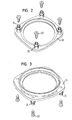
- the gas bag holding element 18 has several integrally molded sleeve-like extensions 20 (see also FIGS. 2 to 7), the extend through openings in the gas bag 16 and in the generator support 12. In these sleeve-like extensions 20 are inserted impact screws 22, via the the gas bag holding element 18, the gas generator 14, the gas bag 16 and the Generator carrier 12 are firmly connected.
- Each impact screw 22 has an attack structure at its head end, which can be designed as a depression or as a projection.
- the attack structure allows using a tool, e.g. an Allen key or Phillips screwdriver, to transmit a rotational movement to the impact screw 22, to release them from the gas bag module 10.
- the gas bag holding element 18 is described in detail below. At the each end has a sleeve-like end facing away from the gas bag holding element 18 Extension 20 on axial slots 24.
- the slots 24 can be annular Base body 25 of the gas bag holding element 18 extend so that the Extension 20 from several, in the example shown four arcuate segments 26 composed.
- the locking shoulders 27 have acting in the insertion direction Bevels 30 on which the passage of the sleeve-like extensions 20 through facilitate the openings in the generator support 12.
- the sleeve-like extension 20 becomes radial direction slightly expanded, so that the locking shoulders 27 the generator support 12 reach behind and lie firmly against the generator support 12, which in Axial direction a positive connection and also a secure clamp connection between the extensions 20 and the generator support 12 results.
- the Impact screw 22 is replaced by a purely translational, axial Force driven into the generator support 12 and the extension 20.
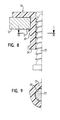
- Beads 28 are formed on the inner wall of the sleeve-like extensions 20, which can run in the axial or circumferential direction (Fig. 9).
- the impact screw 22 has a thread with a sawtooth profile, as can be seen in FIG. 8.
- the beads 28 engage in the sawtooth profile, whereby the impact screw 22nd is additionally secured against loosening by axial pull.
- the beads 28 act as a counter thread, so that the impact screw 22nd like a normal screw.
- the gas bag holding element 18 is preferably made of plastic and can be advantageous be produced in one piece by injection molding. Even the generator carrier 12 and the impact screw 22 can be made of a suitable plastic be made, but can also consist of metal.
- the gas bag module 10 is assembled in a simple manner.
- the gas generator 14 is in the generator support 12 and the gas bag holding element 18 in the Airbag 16 inserted, and the sleeve-like extensions 20 of the airbag holding element through the openings in the gas bag 16 and in the generator support 12 plugged.
- the impact screws 22 are briefly axial force is driven into the sleeve-like extensions 20.
- For one Disassembly need only the impact screws 22 from the sleeve-like Extensions 20 are unscrewed.
- the gas bag module 10 can also be connected via similarly designed connections attached to a vehicle (not shown).
- the gas bag holding element 18 through the flange 50 of the gas generator 14 can be formed, the flange 50 the annular Base body 25 of the gas bag holding element 18 replaced.
- the sleeve-like extensions 20 as individual plastic dowels train, which snap into holes on the flange and through the openings in the Gas generator carrier protrude.
- the sleeve-like extensions 20 could also on the gas bag holding element Generator support 12 may be provided and through openings in the flange 50 or in project a separate gas bag holding element 18, the attachment analogous to Embodiment described above takes place.
Landscapes
- Engineering & Computer Science (AREA)
- Mechanical Engineering (AREA)
- Air Bags (AREA)
Abstract
Description
- Figur 1 eine schematische geschnittene Teilansicht eines erfindungsgemäßen Gassackmoduls, bei dem Bauteile mittels des erfindungsgemäßen Verfahrens aneinander befestigt werden;
- Figur 2 eine schematische perspektivische Ansicht eines Gassackhalteelements zur Verwendung in einem erfindungsgemäßen Gassackmodul;
- Figur 3 das Gassackhalteelement aus Fig. 2 von dessen Oberseite gesehen;
- Figur 4 eine Draufsicht auf das Gassackhalteelement aus Fig. 3;
- Figur 5 einen Schnitt entlang der Linie V-V in Fig. 4;
- Figur 6 einen vergrößerten Ausschnitt X aus Fig. 5, der einem Schnitt entlang der Linie VI-VI in Fig. 4 entspricht;
- Figur 7 einen Schnitt entlang der Linie VII-VII in Fig. 6;
- Figur 8 eine vergrößerte schematische Teilansicht aus Fig. 1;
- Figur 9 eine schematische Schnittansicht entlang der Linie IX-IX in Fig. 8;
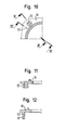
- Figur 10 einen Ausschnitt eines Gassackhalteelements eines Gassackmoduls gemäß einer weiteren Ausführungsform der Erfindung;
- Figur 11 einen Schnitt durch das Gassackhalteelement aus Figur 10 entlang der Linie XI-XI; und
- Figur 12 einen Schnitt durch das Gassackhalteelement aus Figur 10 entlang der Linie XII-XII.
Claims (11)
- Gassackmodul mit einem Gassack (16), einem Gassackhalteelement (18) und einem Generatorträger (12),
dadurch gekennzeichnet, daß das Gassackhalteelement (18) am Generatorträger (12) über wenigstens eine Schlagschraube (22) befestigt ist. - Gassackmodul nach Anspruch 1, dadurch gekennzeichnet, daß das Gassackhalteelement (18) aus Kunststoff besteht.
- Gassackmodul nach einem der vorhergehenden Ansprüche, dadurch gekennzeichnet, daß der Generatorträger (12) aus Kunststoff besteht.
- Gassackmodul nach einem der vorhergehenden Ansprüche, dadurch gekennzeichnet, daß die Schlagschraube (22) aus Kunststoff besteht.
- Gassackmodul nach einem der vorhergehenden Ansprüche, dadurch gekennzeichnet, daß die Schlagschraube (22) ein Sägezahnprofil aufweist.
- Gassackmodul nach einem der vorhergehenden Ansprüche, dadurch gekennzeichnet, daß das Gassackhalteelement (18) wenigstens einen aufweitbaren, hülsenartigen Fortsatz (20) zur Aufnahme einer Schlagschraube (22) aufweist.
- Gassackmodul nach Anspruch 6, dadurch gekennzeichnet, daß der hülsenartige Fortsatz (20) wenigstens einen axialen Schlitz (24) aufweist.
- Gassackmodul nach einem der Ansprüche 6 und 7, dadurch gekennzeichnet, daß der hülsenartige Fortsatz (20) von der Schlagschraube (22) radial aufgespreizt ist.
- Gassackmodul nach einem der Ansprüche 6 bis 8, dadurch gekennzeichnet, daß der hülsenartige Fortsatz (20) eine Rastschulter (27) aufweist, die am Generatorträger (12) anliegt.
- Gassackmodul nach einem der Ansprüche 6 bis 9, dadurch gekennzeichnet, daß an einer Innenwandung des Fortsatzes (20) wenigstens ein Wulst (28) ausgebildet ist, der mit der Schlagschraube (22) in Eingriff ist.
- Verfahren zur Montage und Demontage eines Gassackmoduls, mit einem Gassäck (16), einem Gassackhalteelement (18) und einem Generatorträger (12), dadurch gekennzeichnet, daß zur Montage wenigstens eine mit einem Gewinde versehene Schlagschraube (22) verwendet wird, die durch eine rein translatorische Kraft in zwei miteinander zu befestigende Bauteile getrieben wird und bei der Demontage durch eine rotatorische Bewegung aus den Bauteilen wieder herausgedreht wird.
Applications Claiming Priority (2)
| Application Number | Priority Date | Filing Date | Title |
|---|---|---|---|
| DE20213144U | 2002-08-27 | ||
| DE20213144U DE20213144U1 (de) | 2002-08-27 | 2002-08-27 | Gassackmodul |
Publications (2)
| Publication Number | Publication Date |
|---|---|
| EP1393993A1 true EP1393993A1 (de) | 2004-03-03 |
| EP1393993B1 EP1393993B1 (de) | 2005-12-21 |
Family
ID=7974461
Family Applications (1)
| Application Number | Title | Priority Date | Filing Date |
|---|---|---|---|
| EP03017655A Expired - Lifetime EP1393993B1 (de) | 2002-08-27 | 2003-08-13 | Gassackmodul |
Country Status (4)
| Country | Link |
|---|---|
| US (1) | US20040041373A1 (de) |
| EP (1) | EP1393993B1 (de) |
| DE (3) | DE20213144U1 (de) |
| ES (1) | ES2254835T3 (de) |
Families Citing this family (11)
| Publication number | Priority date | Publication date | Assignee | Title |
|---|---|---|---|---|
| ATE307744T1 (de) * | 2002-06-07 | 2005-11-15 | Autoliv Dev | Elektrisch isolierte befestigungsanordnung für ein airbagmodul |
| DE20317961U1 (de) * | 2003-11-20 | 2004-04-01 | Trw Automotive Safety Systems Gmbh | Gassackmodul |
| US7556281B2 (en) * | 2004-03-16 | 2009-07-07 | Toyoda Gosei Co., Ltd. | Stamped airbag retention members and method of airbag assembly |
| DE202004005994U1 (de) | 2004-04-08 | 2004-06-24 | Takata-Petri Ag | Vorrichtung zur Verbindung eines Airbagmoduls mit einem tragenden Fahrzeugteil |
| DE102004035464B4 (de) * | 2004-07-22 | 2010-07-01 | Trw Automotive Gmbh | Vorrichtung zur Befestigung eines Seitengassackmoduls an einem fahrzeugfesten Bauteil |
| DE102004037300B4 (de) * | 2004-07-31 | 2011-06-09 | Audi Ag | Kraftwagen mit einem Träger und einer Abdeckung |
| DE102011106310B4 (de) * | 2011-07-01 | 2013-01-31 | Trw Automotive Electronics & Components Gmbh | Befestigungsclip |
| DE102012203992A1 (de) * | 2012-03-14 | 2013-09-19 | TAKATA Aktiengesellschaft | Gassackmodul für ein Fahrzeuginsassen-Rückhaltesystem |
| DE202014008432U1 (de) * | 2014-10-23 | 2016-01-26 | Trw Automotive Safety Systems Gmbh | Vorrichtung zur schwingfähigen Befestigung eines Gasgenerators in einem Airbagmodul |
| DE102016005020B4 (de) * | 2016-04-26 | 2019-08-14 | Dalphi Metal Espana, S.A. | Gassackeinheit und Fahrzeuginsassensicherheitssystem mit einer solchen Gassackeinheit sowie Herstellungsverfahren |
| JP6619293B2 (ja) * | 2016-05-23 | 2019-12-11 | 株式会社ダイセル | ガス発生器 |
Citations (4)
| Publication number | Priority date | Publication date | Assignee | Title |
|---|---|---|---|---|
| US3865006A (en) * | 1973-02-14 | 1975-02-11 | Textron Inc | Push type threaded fastener and method of using same |
| DE2644215A1 (de) * | 1976-09-30 | 1978-04-06 | Agfa Gevaert Ag | Schraube |
| EP0709259A1 (de) * | 1994-10-17 | 1996-05-01 | Morton International, Inc. | Beifahrer-Airbag-Einheit mit stirnseitig mittels Ankerstiften verbundenen Deckelkappen |
| DE10155856A1 (de) * | 2000-11-20 | 2002-06-20 | Trw Vehicle Safety Systems | Einschnapp-Airbagmodul |
Family Cites Families (8)
| Publication number | Priority date | Publication date | Assignee | Title |
|---|---|---|---|---|
| US4263833A (en) * | 1979-05-15 | 1981-04-28 | Illinois Tool Works Inc. | Removable one-piece drive rivet |
| US4988119A (en) * | 1988-10-14 | 1991-01-29 | Irvin Automotive Products, Inc. | Vehicle occupant restraint system |
| US5199834A (en) * | 1992-01-14 | 1993-04-06 | Textron Inc. | Air bag stud |
| US5556125A (en) * | 1995-07-21 | 1996-09-17 | Morton International, Inc. | Air bag inflator for snap-on attachment to a steering wheel |
| DE19541180A1 (de) * | 1995-11-04 | 1997-05-07 | Mst Automotive Gmbh | Mittel zur Befestigung eines Airbag-Moduls |
| DE19724029A1 (de) * | 1997-06-06 | 1998-12-24 | Takata Europ Gmbh | Airbag-Vorrichtung |
| US6250665B1 (en) * | 1998-12-15 | 2001-06-26 | Trw Vehicle Safety Systems Inc. | Retainer structure for an inflatable vehicle occupant protection device |
| JP4429492B2 (ja) * | 2000-07-25 | 2010-03-10 | マツダ株式会社 | エアバッグ装置 |
-
2002
- 2002-08-27 DE DE20213144U patent/DE20213144U1/de not_active Expired - Lifetime
-
2003
- 2003-01-08 DE DE20300171U patent/DE20300171U1/de not_active Expired - Lifetime
- 2003-08-13 DE DE50301973T patent/DE50301973D1/de not_active Expired - Fee Related
- 2003-08-13 EP EP03017655A patent/EP1393993B1/de not_active Expired - Lifetime
- 2003-08-13 ES ES03017655T patent/ES2254835T3/es not_active Expired - Lifetime
- 2003-08-21 US US10/645,242 patent/US20040041373A1/en not_active Abandoned
Patent Citations (4)
| Publication number | Priority date | Publication date | Assignee | Title |
|---|---|---|---|---|
| US3865006A (en) * | 1973-02-14 | 1975-02-11 | Textron Inc | Push type threaded fastener and method of using same |
| DE2644215A1 (de) * | 1976-09-30 | 1978-04-06 | Agfa Gevaert Ag | Schraube |
| EP0709259A1 (de) * | 1994-10-17 | 1996-05-01 | Morton International, Inc. | Beifahrer-Airbag-Einheit mit stirnseitig mittels Ankerstiften verbundenen Deckelkappen |
| DE10155856A1 (de) * | 2000-11-20 | 2002-06-20 | Trw Vehicle Safety Systems | Einschnapp-Airbagmodul |
Also Published As
| Publication number | Publication date |
|---|---|
| EP1393993B1 (de) | 2005-12-21 |
| DE20300171U1 (de) | 2003-06-05 |
| ES2254835T3 (es) | 2006-06-16 |
| DE20213144U1 (de) | 2003-01-09 |
| DE50301973D1 (de) | 2006-01-26 |
| US20040041373A1 (en) | 2004-03-04 |
Similar Documents
| Publication | Publication Date | Title |
|---|---|---|
| DE10135492B4 (de) | Komponentenbefestigungseinrichtung | |
| DE69411410T2 (de) | Schnell abnehmbarer Befestiger, insbesondere für Möbel | |
| EP2324522B1 (de) | Anordnung und verfahren zum halten einer mehrzahl von elektrischen kondensatorbaugruppen | |
| DE2732048A1 (de) | Befestigungsvorrichtung | |
| DE102010051372A1 (de) | Verbindungselement mit integrierter Schnappverbindung | |
| EP1343974B2 (de) | Verbindereinrichtung für profile | |
| DE102013004515B4 (de) | Einrichtung zum lösbaren Befestigen eines Montageteils | |
| WO2009141138A1 (de) | Verbindungsbaugruppe zur befestigung eines anbauelements auf einem träger | |
| DE202008010262U1 (de) | Verbindungsbaugruppe zur Befestigung eines Anbauelements auf einem Trägerelement | |
| DE102012003337A1 (de) | Befestigungsvorrichtung | |
| DE3232926A1 (de) | Vorrichtung zur verbindung von konstruktionsteilen oder konstruktionselementen miteinander | |
| EP1393993B1 (de) | Gassackmodul | |
| DE102010008040A1 (de) | Vorrichtung zur lösbaren Verbindung zweier Bauteile | |
| WO2006103265A1 (de) | Befestigungselement zur anbringung auf einem gewindebolzen | |
| EP4105497A1 (de) | Haltevorrichtung und verfahren zu deren anbringung | |
| WO1998038063A1 (de) | Befestigungsvorrichtung für ein fahrzeugteil | |
| EP3508737B1 (de) | Verbindungsanordnung für scheinwerferkomponenten | |
| DE102013105443A1 (de) | Befestigungselement | |
| DE102013208494A1 (de) | Vorrichtung zur werkzeuglosen Verbindung zweier Bauteile | |
| DE19724802A1 (de) | Dichtungselement | |
| WO2004022416A1 (de) | Hybridbauteil mit spritzguss-kunstoffverbindern für kraftfahrzeuge und verfahren zur seiner reparatur | |
| DE102004050674B4 (de) | Befestigungsanordnung für elektrische Komponenten in einem Fahrzeug | |
| DE202013101020U1 (de) | Vorrichtung zum Befestigen eines Trägerelements an der Karosseriestruktur eines Kraftfahrzeugs | |
| DE19908010C1 (de) | Befestigungsvorrichtung für Blenden oder Abdeckungen von Kraftfahrzeugen | |
| EP0823562B1 (de) | Schlaganker zur Befestigung an dünnwandigen Betonteilen |
Legal Events
| Date | Code | Title | Description |
|---|---|---|---|
| PUAI | Public reference made under article 153(3) epc to a published international application that has entered the european phase |
Free format text: ORIGINAL CODE: 0009012 |
|
| AK | Designated contracting states |
Kind code of ref document: A1 Designated state(s): AT BE BG CH CY CZ DE DK EE ES FI FR GB GR HU IE IT LI LU MC NL PT RO SE SI SK TR |
|
| AX | Request for extension of the european patent |
Extension state: AL LT LV MK |
|
| 17P | Request for examination filed |
Effective date: 20040805 |
|
| AKX | Designation fees paid |
Designated state(s): DE ES FR GB IT |
|
| 17Q | First examination report despatched |
Effective date: 20050215 |
|
| GRAP | Despatch of communication of intention to grant a patent |
Free format text: ORIGINAL CODE: EPIDOSNIGR1 |
|
| GRAS | Grant fee paid |
Free format text: ORIGINAL CODE: EPIDOSNIGR3 |
|
| GRAA | (expected) grant |
Free format text: ORIGINAL CODE: 0009210 |
|
| AK | Designated contracting states |
Kind code of ref document: B1 Designated state(s): DE ES FR GB IT |
|
| PG25 | Lapsed in a contracting state [announced via postgrant information from national office to epo] |
Ref country code: GB Free format text: LAPSE BECAUSE OF FAILURE TO SUBMIT A TRANSLATION OF THE DESCRIPTION OR TO PAY THE FEE WITHIN THE PRESCRIBED TIME-LIMIT Effective date: 20051221 |
|
| REG | Reference to a national code |
Ref country code: GB Ref legal event code: FG4D Free format text: NOT ENGLISH |
|
| REF | Corresponds to: |
Ref document number: 50301973 Country of ref document: DE Date of ref document: 20060126 Kind code of ref document: P |
|
| REG | Reference to a national code |
Ref country code: ES Ref legal event code: FG2A Ref document number: 2254835 Country of ref document: ES Kind code of ref document: T3 |
|
| GBV | Gb: ep patent (uk) treated as always having been void in accordance with gb section 77(7)/1977 [no translation filed] |
Effective date: 20051221 |
|
| PGFP | Annual fee paid to national office [announced via postgrant information from national office to epo] |
Ref country code: FR Payment date: 20060803 Year of fee payment: 4 |
|
| ET | Fr: translation filed | ||
| PLBE | No opposition filed within time limit |
Free format text: ORIGINAL CODE: 0009261 |
|
| STAA | Information on the status of an ep patent application or granted ep patent |
Free format text: STATUS: NO OPPOSITION FILED WITHIN TIME LIMIT |
|
| 26N | No opposition filed |
Effective date: 20060922 |
|
| REG | Reference to a national code |
Ref country code: FR Ref legal event code: ST Effective date: 20080430 |
|
| PG25 | Lapsed in a contracting state [announced via postgrant information from national office to epo] |
Ref country code: FR Free format text: LAPSE BECAUSE OF NON-PAYMENT OF DUE FEES Effective date: 20070831 |
|
| PGFP | Annual fee paid to national office [announced via postgrant information from national office to epo] |
Ref country code: DE Payment date: 20080829 Year of fee payment: 6 |
|
| REG | Reference to a national code |
Ref country code: ES Ref legal event code: FD2A Effective date: 20070814 |
|
| PGFP | Annual fee paid to national office [announced via postgrant information from national office to epo] |
Ref country code: IT Payment date: 20080818 Year of fee payment: 6 |
|
| PG25 | Lapsed in a contracting state [announced via postgrant information from national office to epo] |
Ref country code: ES Free format text: LAPSE BECAUSE OF NON-PAYMENT OF DUE FEES Effective date: 20070814 |
|
| PG25 | Lapsed in a contracting state [announced via postgrant information from national office to epo] |
Ref country code: DE Free format text: LAPSE BECAUSE OF NON-PAYMENT OF DUE FEES Effective date: 20100302 |
|
| PG25 | Lapsed in a contracting state [announced via postgrant information from national office to epo] |
Ref country code: IT Free format text: LAPSE BECAUSE OF NON-PAYMENT OF DUE FEES Effective date: 20090813 |