EP1393984A1 - Elektrische Verkabelung eines Fahrzeugs - Google Patents
Elektrische Verkabelung eines Fahrzeugs Download PDFInfo
- Publication number
- EP1393984A1 EP1393984A1 EP03018779A EP03018779A EP1393984A1 EP 1393984 A1 EP1393984 A1 EP 1393984A1 EP 03018779 A EP03018779 A EP 03018779A EP 03018779 A EP03018779 A EP 03018779A EP 1393984 A1 EP1393984 A1 EP 1393984A1
- Authority
- EP
- European Patent Office
- Prior art keywords
- cable
- brake
- shield
- electrical cables
- carriage
- Prior art date
- Legal status (The legal status is an assumption and is not a legal conclusion. Google has not performed a legal analysis and makes no representation as to the accuracy of the status listed.)
- Granted
Links
- 239000002184 metal Substances 0.000 claims description 5
- 229910052751 metal Inorganic materials 0.000 claims description 5
- 230000000712 assembly Effects 0.000 claims description 3
- 238000000429 assembly Methods 0.000 claims description 3
- 238000009429 electrical wiring Methods 0.000 claims description 3
- 239000011888 foil Substances 0.000 claims description 2
- 239000011810 insulating material Substances 0.000 claims 1
- 238000012216 screening Methods 0.000 abstract description 7
- 238000009413 insulation Methods 0.000 abstract description 2
- 230000001105 regulatory effect Effects 0.000 description 8
- 210000004907 gland Anatomy 0.000 description 6
- 230000033001 locomotion Effects 0.000 description 6
- 230000006870 function Effects 0.000 description 5
- 239000013307 optical fiber Substances 0.000 description 5
- 238000004146 energy storage Methods 0.000 description 4
- 230000005540 biological transmission Effects 0.000 description 3
- 230000000295 complement effect Effects 0.000 description 3
- 239000000463 material Substances 0.000 description 3
- 238000012544 monitoring process Methods 0.000 description 3
- 230000011664 signaling Effects 0.000 description 3
- RYGMFSIKBFXOCR-UHFFFAOYSA-N Copper Chemical compound [Cu] RYGMFSIKBFXOCR-UHFFFAOYSA-N 0.000 description 2
- 230000033228 biological regulation Effects 0.000 description 2
- 239000004020 conductor Substances 0.000 description 2
- 230000008878 coupling Effects 0.000 description 2
- 238000010168 coupling process Methods 0.000 description 2
- 238000005859 coupling reaction Methods 0.000 description 2
- 238000011161 development Methods 0.000 description 2
- 230000018109 developmental process Effects 0.000 description 2
- 239000012774 insulation material Substances 0.000 description 2
- 238000010008 shearing Methods 0.000 description 2
- 230000020347 spindle assembly Effects 0.000 description 2
- 229920000049 Carbon (fiber) Polymers 0.000 description 1
- 238000004026 adhesive bonding Methods 0.000 description 1
- 239000004917 carbon fiber Substances 0.000 description 1
- 238000006243 chemical reaction Methods 0.000 description 1
- 230000006835 compression Effects 0.000 description 1
- 238000007906 compression Methods 0.000 description 1
- 230000001276 controlling effect Effects 0.000 description 1
- 229910052802 copper Inorganic materials 0.000 description 1
- 239000010949 copper Substances 0.000 description 1
- 230000001419 dependent effect Effects 0.000 description 1
- 238000013461 design Methods 0.000 description 1
- 239000000835 fiber Substances 0.000 description 1
- 239000000945 filler Substances 0.000 description 1
- 238000009434 installation Methods 0.000 description 1
- 238000002955 isolation Methods 0.000 description 1
- 238000005259 measurement Methods 0.000 description 1
- VNWKTOKETHGBQD-UHFFFAOYSA-N methane Chemical compound C VNWKTOKETHGBQD-UHFFFAOYSA-N 0.000 description 1
- 230000002093 peripheral effect Effects 0.000 description 1
- 239000011253 protective coating Substances 0.000 description 1
- 230000001681 protective effect Effects 0.000 description 1
- 230000002787 reinforcement Effects 0.000 description 1
- 238000000926 separation method Methods 0.000 description 1
- 230000008054 signal transmission Effects 0.000 description 1
- 238000012795 verification Methods 0.000 description 1
- 238000004804 winding Methods 0.000 description 1
Images


Classifications
-
- H—ELECTRICITY
- H01—ELECTRIC ELEMENTS
- H01B—CABLES; CONDUCTORS; INSULATORS; SELECTION OF MATERIALS FOR THEIR CONDUCTIVE, INSULATING OR DIELECTRIC PROPERTIES
- H01B9/00—Power cables
- H01B9/003—Power cables including electrical control or communication wires
-
- B—PERFORMING OPERATIONS; TRANSPORTING
- B60—VEHICLES IN GENERAL
- B60T—VEHICLE BRAKE CONTROL SYSTEMS OR PARTS THEREOF; BRAKE CONTROL SYSTEMS OR PARTS THEREOF, IN GENERAL; ARRANGEMENT OF BRAKING ELEMENTS ON VEHICLES IN GENERAL; PORTABLE DEVICES FOR PREVENTING UNWANTED MOVEMENT OF VEHICLES; VEHICLE MODIFICATIONS TO FACILITATE COOLING OF BRAKES
- B60T13/00—Transmitting braking action from initiating means to ultimate brake actuator with power assistance or drive; Brake systems incorporating such transmitting means, e.g. air-pressure brake systems
- B60T13/74—Transmitting braking action from initiating means to ultimate brake actuator with power assistance or drive; Brake systems incorporating such transmitting means, e.g. air-pressure brake systems with electrical assistance or drive
-
- B—PERFORMING OPERATIONS; TRANSPORTING
- B61—RAILWAYS
- B61D—BODY DETAILS OR KINDS OF RAILWAY VEHICLES
- B61D49/00—Other details
-
- H—ELECTRICITY
- H01—ELECTRIC ELEMENTS
- H01B—CABLES; CONDUCTORS; INSULATORS; SELECTION OF MATERIALS FOR THEIR CONDUCTIVE, INSULATING OR DIELECTRIC PROPERTIES
- H01B11/00—Communication cables or conductors
- H01B11/22—Cables including at least one electrical conductor together with optical fibres
-
- F—MECHANICAL ENGINEERING; LIGHTING; HEATING; WEAPONS; BLASTING
- F16—ENGINEERING ELEMENTS AND UNITS; GENERAL MEASURES FOR PRODUCING AND MAINTAINING EFFECTIVE FUNCTIONING OF MACHINES OR INSTALLATIONS; THERMAL INSULATION IN GENERAL
- F16D—COUPLINGS FOR TRANSMITTING ROTATION; CLUTCHES; BRAKES
- F16D66/00—Arrangements for monitoring working conditions, e.g. wear, temperature
- F16D2066/001—Temperature
-
- F—MECHANICAL ENGINEERING; LIGHTING; HEATING; WEAPONS; BLASTING
- F16—ENGINEERING ELEMENTS AND UNITS; GENERAL MEASURES FOR PRODUCING AND MAINTAINING EFFECTIVE FUNCTIONING OF MACHINES OR INSTALLATIONS; THERMAL INSULATION IN GENERAL
- F16D—COUPLINGS FOR TRANSMITTING ROTATION; CLUTCHES; BRAKES
- F16D66/00—Arrangements for monitoring working conditions, e.g. wear, temperature
- F16D2066/005—Force, torque, stress or strain
-
- Y—GENERAL TAGGING OF NEW TECHNOLOGICAL DEVELOPMENTS; GENERAL TAGGING OF CROSS-SECTIONAL TECHNOLOGIES SPANNING OVER SEVERAL SECTIONS OF THE IPC; TECHNICAL SUBJECTS COVERED BY FORMER USPC CROSS-REFERENCE ART COLLECTIONS [XRACs] AND DIGESTS
- Y02—TECHNOLOGIES OR APPLICATIONS FOR MITIGATION OR ADAPTATION AGAINST CLIMATE CHANGE
- Y02T—CLIMATE CHANGE MITIGATION TECHNOLOGIES RELATED TO TRANSPORTATION
- Y02T30/00—Transportation of goods or passengers via railways, e.g. energy recovery or reducing air resistance
Definitions
- the invention relates to an electrical wiring of a vehicle or Vehicle train, in particular a rail vehicle, which one between two Components, assemblies or cars of the vehicle or vehicle train running Collective cable includes, in which a plurality of electrical cables are combined, according to the preamble of claim 1.
- the service brake unit includes a brake force generator for applying and / or Release the brake in the form of an electric motor drive.
- the memory brake unit unifint at least one energy storage for storing and releasing energy for Braking the brake as an operational emergency brake in the sense of an underlaid Safety level in case of failure of the service brake unit and / or as parking or Parking brake.
- the memory brake unit is generally known as a spring brake educated.
- a power converter ensures the implementation of the braking force generator and / or energy emitted by the energy storage in a Bremszuspannzi.
- Electromotive drive is usually through a control and power electronics too slip-controlled (anti-skid control) and / or load-corrected braking can be controlled.
- the shield must be grounded or earthed be.
- the signal transmission disturbing potential equalization currents between the mass of the control, signaling and / or power supply facilities haven and the mass of the brake application device or of the bogie be prevented. Such currents can in extreme cases to a Damage to the cables.
- the present invention is therefore an object of an electric Wiring of the type mentioned above to provide, on the one hand a good shielding against electromagnetic interference ensured and on the other hand prevents the occurrence of potential equalization currents.
- the isolatorische separation of the individual shields prevents from the Total shield in conjunction with each only one-sided and to the mass of the each other component, assembly or the other car existing Connection of the individual shields and the total shield that through the Shields an electrically conductive connection between the mass of one Component, assembly or one carriage and the mass of the other component, Assembly or the other car arises. Consequently, over the shields no potential equalization currents due to different potentials of the Components, assemblies or cars run, which are mainly digital signals of a Data bus and the sensor signals interfere sensitively.
- the overall screen surrounds the individual screens and therebetween insulation, i. one Dielectric is present, there is also a capacitive coupling of the Overall screen with the individual screens. This capacitive coupling causes in Advantageously, that high-frequency interference are derived.
- the insulating layer is through Air and / or other insulation material and / or by one or more Cable sheaths are formed, within each of which a group of electrical cables is stirred, wherein at least some of the cable sheaths of the groups of electrical cables are provided with mutually electrically isolated individual shields.
- Such Arrangement is especially useful when, by the electrical cables one by itself shielded group signals or currents are conducted, which are not simultaneously occur or do not influence each other. In such a case can on a Single shielding of each individual cable of the group can be dispensed with.
- All Electrical cables and / or groups of electrical cables are preferably within a Sammelraitmantels the collective cable out, which with the Overall shield is provided, wherein the overall shield preferably at the radially inner peripheral surface of the collecting cable sheath is arranged. This is the Overall shield protected against external influences.
- the collective cable runs between one on one Car body of a car of a rail vehicle arranged connection and on a bogie of the car arranged Bremszuspann issued and serves for Connection of the latter with control, signaling and / or power supply facilities.
- a car-side detachable connection and a Bremszuspein With a respective connector, the overall screen by means of the Bremsspann droves ses connection to the mass of the bogie and the individual screens by means of car-side connector connected to the mass of the car body. Conceivable but is also a reversal of the connections such that the overall screen by means of car-side connector with the body of the car body and the individual screens by means of the brake booster side connector with the mass of Bogie is connected It is crucial that no electrically conductive Connection between the overall shield and the individual shields comes.
- the entire shield is connected to a shield cable gland of a Rundsteckers a connector clamped surface, so that the shield also on the interface is consistent and unbroken.
- the designated in Fig. 1 in total with 1, preferred embodiment of a Electromechanical brake application device forms one of several Bremszuspann wornen a rail vehicle, such as a S-Bru.
- the Brake application device 1 includes a brake actuator 2 with a Service brake unit and a memory brake unit
- the service brake unit has one electric drive, for example, an electric servomotor 4, in one Actuator 6 of the brake actuator 2 is housed.
- a mechanical one Power converter 8 is used to implement the output from the brake actuator 2 energy in a brake application movement.
- the servo motor 4 sets a coaxial brake spindle 10 in rotation, which by the Power converter 8 in a Bremszuspannzi of brake pads 12 toward a wave brake disk 14 are converted.
- the power converter 8 includes under Others, a nut / spindle assembly 16 with a rotatable on the brake spindle 10 mounted spindle nut 18, which upon rotation of the brake spindle 10 linear movements in the direction of the spindle axis 42 can perform.
- the storage spring 24 is part of the storage brake unit and serves as energy storage for Saving and releasing energy to apply the brake as operational Emergency brake in the sense of an underlying safety level in the event of failure of the Service brake and / or parking or parking brake. Both the operating as also the memory brake unit act on the connecting rod 20.
- In Bremslinate too is the Memory spring 24 by a locking device 26 in the biased position held.
- a connecting rod 28 of the connecting rod 20 protrudes from the sliding sleeve 22 and is at one Brake lever 36 is articulated by means of a hinge 40 perpendicular to the spindle axis 42.
- a hinge 40 perpendicular to the spindle axis 42.
- the other end of the brake lever 36 acts on an eccentric with a Eccentric shaft 46 which is articulated to a caliper lever 48, which together with a further caliper lever 50 forms a brake caliper 52.
- a caliper lever 48 At one end of the pliers lever 48, 50 respectively pad holder 54 are arranged with brake pads 12, which in the direction of Axle of the shaft brake disc 14 are displaceable.
- the of the brake pads 12th remote ends of the pliers levers 48, 50 are connected to each other via a Push rod actuator 56 connected, which is designed preferably electrically operated.
- the arrangement described also forms part of the power converter 8, the from the Actuator 4 or caused by the memory spring 24 extension movements of the connecting rod 20th in a Bremszuspanniolo the brake pads 12 in the direction of the brake disc 14th converts.
- the hinge pin of the joint 40 is preferably by a Scherkraftmeßbolzen 58 educated.
- the Scherkraftmeßbolzen 58 is not at least one of scale reasons provided measuring sensor for measuring sizes, from which the to the Brake pads 12 acting braking force is indirectly or directly derivable.
- DMS strain gauges
- the transducer by strain gauges (DMS) formed on the circumference of Scherkraftmeßbolzens 58 preferably by gluing such are fixed so that they due to the opposing shear forces caused shearing deformations of Scherkraftmeßbolzens 58 proportional signals produce.
- DMS strain gauges
- the Scherkraftmeßbolzen 58 or in addition to this can also be or a plurality of strain gauges may be disposed on the brake lever 36 to recover from the deformations the brake lever 36 to derive the braking forces can.
- a transmitter containing a strain gauge bridge circuit finds a Conversion of shear deformation signals into signals for the respective brake pads 12 acting Ist-Zuspannkraft instead, which via a signal line 59 to a control and Control device 60 are forwarded to a reference to a target-actual comparison Control difference between a target clamping force and the actual clamping force to calculate.
- the braking force setpoint specification is based, for example, on reaching a required target clamping force in the shortest possible time, for example, 75% of the maximum Clamping force in 0.3 seconds.
- the control and regulating device 60 controls a power section 62, which in Dependence of the calculated control difference an operating current for the servomotor 4 which controls by a to a between the power section 62 and the servo motor. 4 extending electrical line 64 connected current sensor 66 is measured, wherein a feedback to the control and regulating device 60 by a corresponding, via a signal line 68 recirculated motor current signal is carried out. Except for the Einregelung one Target clamping force are used in the control and regulating device 60 signals for the actual clamping forces and for the respective motor current for monitoring the Force control and functionality of the brake application device 1 at safety-related braking. For verification of the measurement results can also On the drive side by the current sensor 66 measured motor current in the control and Regulating device 60 are matched with the signal for the actual application force.
- An arranged in the motor winding of the servomotor 4 temperature sensor 70 is used for Temperature monitoring during operation and provides via a signal line 72nd corresponding signals to the control and regulating device 60.
- more Temperature sensors for temperature monitoring of one or more Components of the brake application device 1 may be provided, for example a Temperature sensor for measuring the temperature of the power section 62.
- a temperature sensor for measuring ambient temperature values to the control and Control device 60 ranem.
- the brake application device 1 is preferably for generating load-corrected and / or slip-controlled braking forces, wherein under a load-corrected Braking a substantially to the respective present weight of Rail vehicle adapted braking force and under a slip-controlled braking force a braking force is to be understood by which the braking with ideal Wheel slip occurs (anti-slip control).
- control and regulating device 60 corresponding control functions.
- the control and regulating electronics 60 is preferably in housed a separate, not shown for reasons of scale housing, which on the actuator housing 6 is flanged. Alternatively, could the control and Control electronics 60 but also far from the Bremszuspann Huawei in a car of the S-Bru be arranged.
- the brake application device 1 is mounted on a bogie 74 of a carriage 76 of the rail vehicle, wherein the brake disk 14 with a bogie 74 mounted shaft 78 is rotatably connected.
- the bogie 74 can rotary and Vertical movements with respect to a car body 80 of the carriage 76 run.
- At least between the Bremszuspann acknowledged 1 and the car body 80 of the carriage 76 are all electrical cables and / or optical fibers in a single bus 84 summarized, which with the Bremszuspann engaged 1 and / or with the carriage box-side terminal 82 is detachably connected.
- both ends of the collecting cable 84 are both on the carriage side as well brake booster device side by means of a releasable plug or screw connection 86, 88 connectable, wherein the collecting cable 84, the distance between one on the ground the car body 76 arranged terminal box 82 and a housing 90 of the Brake application device 1 bridged is conceivable also any other kind of solvable Connection.
- the carriage-side plug or screw for example, by a connector 86 with shield bracket and the brake chuck side Plug connection be realized by a round plug 88 with shield support.
- the collective cable 84 could Also by means of a karêt cable entry into the housing 90 of Open brake clamp 1 or in the terminal box 82. It is crucial that at least one releasable connection 86, 88 for the collecting cable 84 is present.
- the terminal box 82 is connected to a terminal row, not shown for reasons of scale into which ends of cables and lines open out, which of the control, Signalgeber- and / or power supply facilities are brought forth.
- the single ones Terminals of the terminal row are in turn with associated contacts of car-side releasable connection 86 connected.
- the collecting cable 84 is longer than the shortest connection between the brake booster side and the car side releasable connection 86, 88, to allow unimpeded movement of the Bogie 74 with respect to the car body 80 to allow.
- the overall shield 100 surrounds the individual shields 99 and is of these one or more isolation layers separated, which for example by air and / or a other insulation material and / or by the cable sheath 98 of the groups 92, 94, 96, 97 of Cables is formed. Furthermore, the individual shields 99 are preferably by the Cable sheaths 98 also insulated from each other.
- the control lines 96 for triggering Safety and parking brakes are preferably along the radially inner surface of the Overall shield 100 arranged with circumferential spacing and surround the other cables and lines 92, 94, 97.
- the control and regulation electronics shown schematically in FIG 60 is preferably in its own, on the housing 90 of the brake application device. 1 Flanged housing housed Therefore, appropriate control lines are not here Component of the collecting cable 84.
- control electronics 60 not as preferred on the housing 90th arranged the Bremszuspann Road 1, but fem of this example in or on a carriage of the rail vehicle, preferably on an underbody of the Trolley is arranged in the collective cable 102, the corresponding Control lines to be integrated as electrical lines or optical fibers.
- the cables and lines 104, 106, 108, 110, 112 packed as close as possible, the interstices with a filler 114th are poured out or contain air.
- the statements apply to the previously described Embodiment.
- the Collective cable sheath 116 have a further protective coating, for example in shape a protective tube, which also be integrated into the collective cable sheath 116 itself can. All cable sheaths 105 and in particular the collective cable sheath 116 exist Made of a material that is resistant to high temperature fluctuations, large Deformations, vibrations and impact load is.
- the overall shield 100 of the collector cable 84 according to the preferred embodiment by means of the brake booster side connector 88 with the mass of Bogie 74 electrically connected.
- the overall shield 100 is at one Shield cable gland 120 of a circular connector 122 of the connector 88 area clamped, as shown in Fig. 5 shows the circular connector 122 has a shield support in Form of an adapter 124 with a cone-shaped radially inner clamping surface on, against which a cone ring 126 with complementary conical clamping surface means an axial pressure screw 128 is tensioned to an exposed, radially outward bent end 130, preferably made of metal mesh Total shield 100 between the clamping surfaces to clamp.
- the Compression screw 128 and the cone ring 126, a rubber ring 132 and a disc 134th axially interposed are not shown with plug contacts of Round plug 122 in conjunction.
- the adapter 124, the cone ring 126 and the Pressure screw 128 are made of an electrically conductive material and form together the shield cable gland 120.
- a socket is also made of electrically conductive material and is connected to the ground of the Bogie 74 electrically connected.
- the plug 138 is in a complementary, on the terminal box 82 of the car body 80th arranged socket 144 inserted, the contacts with corresponding terminals of the Terminal row in connection.
- the connector 86 of the device Shield contact strap 140 with a complementary shield contact bow 146 of the socket 144 in electrically conductive connection.
- the Schirmuttonbügel 146 is in turn by a ground strap 148 electrically connected to the car body 80, so that the Single shields 99 of the collecting cable 84 placed on the mass of the car body 80 are.
- the overall shield 100 to the mass of the bogie 74 and the Single shields 99 to the mass of the car body 80 to put can also be reverse assignment, i. that the total shield 100 to the mass of the Car body 80 and the individual shields 99 to the mass of the bogie 74th be connected. It is crucial that the total shield 100 the Single shields 99 at least partially surrounds and with respect to these electrically is isolated.
Landscapes
- Engineering & Computer Science (AREA)
- Transportation (AREA)
- Mechanical Engineering (AREA)
- Braking Systems And Boosters (AREA)
Abstract
Description
- Die Energieversorgung eines Leistungsteils der Bremszuspanneinrichtung zum Auf- bzw. zum Abbau der Zuspannkraft;
- die Energieversorgung der Steuerung und Regelung der Bremszuspanneinrichtung;
- die Übermittlung von Steuersignalen wie beispielsweise das momentane Bremsanforderungssignal, Signale zum Auslösen der Parkbremsfunktion, zum Auslösen der Hilfsbremsfunktion etc.;
- die Übermittlung von Sensorsignalen wie beispielsweise die Signale eines Impulsgebers zur Ermittlung der Raddrehzahl oder von Endlagenschaltern;
- die Übermittlung von Diagnosedaten.
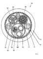
- Fig.1
- eine schematische Darstellung einer elektromechanischen Bremszuspanneinrichtung;
- Fig.2
- eine schematische Darstellung eines bevorzugten Ausführungsbeispiels einer elektrischen Verkabelung zwischen einem an einem Wagenboden angeordneten Klemmkasten und der Bremszuspanneinrichtung von Fig.1 in Form eines Sammelkabels;
- Fig.3
- einen Querschnitt durch das Sammelkabel von Fig.2;
- Fig.4
- einen Querschnitt durch ein weiteres Sammelkabel;
- Fig.5
- eine schematische Darstellung einer bremszuspanneinrichtungsseitigen Kabel-Steckverbindung;
- Fig.6
- eine schematische Darstellung einer wagenseitigen Kabel-Steckverbindung.
- mehrere Impulsgebersignal- und Versorgungskabel 92, welche in einer Gruppe mit eigenem Kabelmantel 98 und eigener Abschirmung 99 zusammengefaßt sind, welche Signale eines an der Radnabe angeordneten Impulsgebers zur Drehzahlmessung des Rades sowie die für den Impulsgeber notwendige elektrische Energie übertragen,
- mehrere Feldbuskabel 94 eines CAN-Busses aus Kupfer, welche in einer Gruppe mit eigenem Kabelmantel 98 und eigener Abschirmung 99 zusammengefaßt sind,
- Steuerleitungen 96 zum Auslösen von Sicherheits- und Parkbremsungen,
- mehrere Leitungen 97 zur Leistungsversorgung des Stellmotors mit eigenem Kabelmantel 98 und eigener Abschirmung 99.
- mehrere Leistungsversorgungskabel 104 mit eigenem Kabelmantel 105 und eigener Abschirmung 107,
- mehrere Impulsgebersignal- und Versorgungskabel 106 mit eigenem Kabelmantel 105 und eigener Abschirmung 107,
- Feldbuskabel 108 als Lichtwellenleiter,
- Steuerleitungen 110 zur Ansteuerung und Versorgung einer elektrischen Hilfslöseeinrichtung sowie Steuerleitungen 112 zum Auslösen von Sicherheits- und Parkbremsungen mit eigenem Kabelmantel 105.
- 1
- Bremszuspanneinrichtung
- 2
- Bremsaktuator
- 4
- Stellmotor
- 6
- Aktuatorgehäuse
- 8
- Kraftumsetzer
- 10
- Bremsspindel
- 12
- Bremsbelag
- 14
- Bremsscheibe
- 16
- Mutter-/Spindel-Baueinheit
- 18
- Spindelmutter
- 20
- Pleuel
- 22
- Schiebehülse
- 24
- Speicherfeder
- 26
- Verriegelungseinrichtung
- 28
- Pleuelkopf
- 36
- Bremshebel
- 40
- Gelenk
- 42
- Spindelachse
- 46
- Exzenterwelle
- 48
- Zangenhebel
- 50
- Zangenhebel
- 52
- Bremszange
- 54
- Belaghalter
- 56
- Druckstangensteller
- 58
- Scherkraftmeßbolzen
- 59
- Signalleitung
- 60
- Steuer- und Regeleinrichtung
- 62
- Leistungsteil
- 64
- elektrische Leitung
- 66
- Stromsensor
- 68
- Signalleitung
- 70
- Temperatursensor
- 72
- Signalleitung
- 74
- Drehgestell
- 76
- Wagen
- 78
- Achse
- 80
- Wagenkasten
- 82
- Klemmkasten
- 84
- Sammelkabel
- 86
- Steckverbinder
- 88
- Steckverbinder
- 90
- Gehäuse
- 91
- Sammelkabelmantel
- 92
- Impulsgebersignal- und Versorgungskabel
- 94
- Feldbuskabel
- 96
- Steuerleitungen
- 97
- Leitungen
- 98
- Kabelmantel
- 99
- Abschirmung
- 100
- Gesamtabschirmung
- 102
- Sammelkabel
- 104
- Leistungsversorgungskabel
- 105
- Kabelmantel
- 106
- Impulsgeber- und Versorgungskabel
- 107
- Abschirmung
- 108
- Feldbuskabel
- 110
- Steuerleitungen
- 112
- Steuerleitungen
- 114
- Füllmaterial
- 116
- Sammelkabelmantel
- 118
- Gesamtabschirmung
- 120
- Schirmkabelverschraubung
- 122
- Rundstecker
- 124
- Adapter
- 126
- Konusring
- 128
- Druckschraube
- 130
- Ende
- 132
- Gummiring
- 134
- Scheibe
- 138
- Stecker
- 140
- Schirmkontaktbügel
- 142
- Klemmschellen
- 144
- Buchse
- 146
- Schirmkontaktbügel
- 148
- Masseband
Claims (12)
- Elektrische Verkabelung eines Fahrzeugs oder Fahrzeugzuges, insbesondere eines Schienenfahrzeugs, welche ein zwischen zwei Komponenten, Baugruppen oder Wagen des Fahrzeugs oder Fahrzeugzuges verlaufendes Sammelkabel beinhaltet, in welchem mehrere elektrische Kabel zusammengefaßt sind, dadurch gekennzeichnet, daß das Sammelkabel (84; 102) eine Gesamtabschirmung (100; 118) und wenigstens eines der elektrischen Kabel eine Einzelabschirmung (99; 107) aufweist, wobei letztere innerhalb der Gesamtabschirmung (100; 118) verläuft und von dieser durch eine oder mehrere Isolationsschichten (98; 105) getrennt ist und wobei die Einzelabschirmung (99; 107) mit der Masse der einen Komponente, Baugruppe (80) oder dem einen Wagen und die Gesamtabschirmung (100; 118) mit der Masse der anderen Komponente, Baugruppe (74) oder dem anderen Wagen elektrisch leitend verbunden ist oder umgekehrt.
- Vorrichtung nach Anspruch 1, dadurch gekennzeichnet, daß die Isolationsschicht durch Luft und/oder ein anderes Isolationsmaterial (114) und/oder durch einen oder mehrere Kabelmäntel (98; 105) gebildet wird, innerhalb welchen jeweils eine Gruppe (92, 94, 96, 97;104, 106, 108, 110, 112) von elektrischen Kabeln gerührt ist.
- Vorrichtung nach Anspruch 2, dadurch gekennzeichnet, daß wenigstens einige der Kabelmäntel (98; 105) der Gruppen (92, 94, 96, 97;104, 106, 108, 110, 112) von elektrischen Kabeln mit gegeneinander elektrisch isolierten Einzelabschirmungen (99; 107) versehen sind.
- Vorrichtung nach Anspruch 3, dadurch gekennzeichnet, daß sämtliche elektrischen Kabel und/oder Gruppen (92, 94, 96, 97;104, 106, 108, 110, 112) von elektrischen Kabeln innerhalb eines Sammelkabelmantels (91; 116) des Sammelkabels (84; 102) geführt sind, welcher mit der Gesamtabschirmung (100; 118) versehen ist.
- Vorrichtung nach Anspruch 4, dadurch gekennzeichnet, daß die Gesamtabschirmung (100; 118) an der radial inneren Umfangsfläche des Sammelkabelmantels (91; 116) angeordnet ist.
- Vorrichtung nach einem der vorhergehenden Ansprüche, dadurch gekennzeichnet, daß die Gesamtabschirmung (100; 118) und/oder die Einzelabschirmungen (99; 107) ein Metallgeflecht und/oder eine elektrisch leitende Folie beinhalten.
- Verkabelung nach einem der vorhergehenden Ansprüche, dadurch gekennzeichnet, daß das Sammelkabel (84; 102) zwischen einem an einem Wagenkasten (80) eines Wagens (76) eines Schienenfahrzeugs angeordneten Anschluß (82) und einer an einem Drehgestell (74) des Wagens (76) angeordneten Bremszuspanneinrichtung (1) verläuft und zur Verbindung letzterer mit Steuer-, Signalgeber- und/oder Energieversorgungseinrichtungen (62) dient.
- Vorrichtung nach Anspruch 7, dadurch gekennzeichnet, daß wenigstens ein Ende des Sammelkabels (84; 102) mittels einer lösbaren Verbindung (86, 88) am Wagenkasten (80) oder an der Bremszuspanneinrichtung (1) befestigt ist.
- Vorrichtung nach Anspruch 8, dadurch gekennzeichnet, daß die wagenseitige lösbare Verbindung und eine bremszuspanneinrichtungsseitige Verbindung durch je einen Steckverbinder (86; 88) gebildet wird.
- Vorrichtung nach Anspruch 9, dadurch gekennzeichnet, daß die Gesamtabschirmung (100; 118) mittels des bremszuspanneinrichtungsseitigen Steckverbinders (88) an die Masse des Drehgestells (74) angeschlossen ist.
- Vorrichtung nach Anspruch 10, dadurch gekennzeichnet, daß die Gesamtabschirmung (100; 118) an einem elektrisch leitenden Steckergehäuses (122, 124, 132, 134) eines Steckers (120) des bremszuspanneinrichtungsseitigen Steckverbinders (88) flächig geklemmt ist.
- Vorrichtung nach Anspruch 11, dadurch gekennzeichnet, daß die Einzelschirme (99; 107) mittels des wagenseitigen Steckverbinders (86) an die Masse des Wagenkastens (80) angeschlossen sind.
Applications Claiming Priority (2)
| Application Number | Priority Date | Filing Date | Title |
|---|---|---|---|
| DE10239695A DE10239695C1 (de) | 2002-08-29 | 2002-08-29 | Elektrische Verkabelung eines Fahrzeugs |
| DE10239695 | 2002-08-29 |
Publications (2)
| Publication Number | Publication Date |
|---|---|
| EP1393984A1 true EP1393984A1 (de) | 2004-03-03 |
| EP1393984B1 EP1393984B1 (de) | 2007-01-17 |
Family
ID=29225197
Family Applications (1)
| Application Number | Title | Priority Date | Filing Date |
|---|---|---|---|
| EP03018779A Expired - Lifetime EP1393984B1 (de) | 2002-08-29 | 2003-08-28 | Elektrische Verkabelung eines Fahrzeugs |
Country Status (2)
| Country | Link |
|---|---|
| EP (1) | EP1393984B1 (de) |
| DE (2) | DE10239695C1 (de) |
Cited By (3)
| Publication number | Priority date | Publication date | Assignee | Title |
|---|---|---|---|---|
| CN101155701B (zh) * | 2005-12-22 | 2010-09-29 | 塞夫·霍兰德有限公司 | 轮毂装置 |
| US20210241936A1 (en) * | 2020-02-04 | 2021-08-05 | Structured Home Wiring Direct, LLC | Composite Hybrid Cables and Methods of Manufacturing and Installing the Same |
| EP3971918A4 (de) * | 2019-05-16 | 2023-05-17 | LS Cable & System Ltd. | Verbundkabel für ein fahrzeug und verbundkabelanordnung damit |
Families Citing this family (4)
| Publication number | Priority date | Publication date | Assignee | Title |
|---|---|---|---|---|
| JP4577605B2 (ja) * | 2004-07-30 | 2010-11-10 | 日立オートモティブシステムズ株式会社 | 電動ディスクブレーキ |
| WO2007021192A1 (en) * | 2005-08-15 | 2007-02-22 | Fugro-Geoteam As | Generic tow lead-in for streamers |
| US7432446B2 (en) | 2005-09-28 | 2008-10-07 | Symbol Technologies, Inc. | Coiled electronic article surveillance (EAS) cable |
| DE102014109269B4 (de) * | 2014-07-02 | 2021-04-08 | Lisa Dräxlmaier GmbH | Energieversorgungssystem für ein Kraftfahrzeug |
Citations (5)
| Publication number | Priority date | Publication date | Assignee | Title |
|---|---|---|---|---|
| GB502122A (en) * | 1937-10-19 | 1939-03-13 | Western Electric Co | Improvements in electric cables having shielded conductors |
| WO1994020968A1 (de) * | 1993-03-04 | 1994-09-15 | Aeg Schienenfahrzeuge Gmbh | Elektromagnetisch abgeschirmtes kabel bzw. leitung |
| EP0685239A2 (de) * | 1994-06-03 | 1995-12-06 | Siemens Medical Systems, Inc. | Flexibles Kabel für mehrere Parameter |
| WO2001091137A2 (en) * | 2000-05-19 | 2001-11-29 | Spirent Communications | Multiple shielded cable |
| US20010054123A1 (en) * | 1996-09-16 | 2001-12-20 | Gregory K. Henrikson | Ieee 1394 active wall disconnect and aircraft qualified cable |
Family Cites Families (1)
| Publication number | Priority date | Publication date | Assignee | Title |
|---|---|---|---|---|
| DE19945701A1 (de) * | 1999-09-23 | 2001-04-19 | Knorr Bremse Systeme | Bremsaktuator |
-
2002
- 2002-08-29 DE DE10239695A patent/DE10239695C1/de not_active Revoked
-
2003
- 2003-08-28 EP EP03018779A patent/EP1393984B1/de not_active Expired - Lifetime
- 2003-08-28 DE DE50306293T patent/DE50306293D1/de not_active Expired - Lifetime
Patent Citations (5)
| Publication number | Priority date | Publication date | Assignee | Title |
|---|---|---|---|---|
| GB502122A (en) * | 1937-10-19 | 1939-03-13 | Western Electric Co | Improvements in electric cables having shielded conductors |
| WO1994020968A1 (de) * | 1993-03-04 | 1994-09-15 | Aeg Schienenfahrzeuge Gmbh | Elektromagnetisch abgeschirmtes kabel bzw. leitung |
| EP0685239A2 (de) * | 1994-06-03 | 1995-12-06 | Siemens Medical Systems, Inc. | Flexibles Kabel für mehrere Parameter |
| US20010054123A1 (en) * | 1996-09-16 | 2001-12-20 | Gregory K. Henrikson | Ieee 1394 active wall disconnect and aircraft qualified cable |
| WO2001091137A2 (en) * | 2000-05-19 | 2001-11-29 | Spirent Communications | Multiple shielded cable |
Cited By (6)
| Publication number | Priority date | Publication date | Assignee | Title |
|---|---|---|---|---|
| CN101155701B (zh) * | 2005-12-22 | 2010-09-29 | 塞夫·霍兰德有限公司 | 轮毂装置 |
| EP3971918A4 (de) * | 2019-05-16 | 2023-05-17 | LS Cable & System Ltd. | Verbundkabel für ein fahrzeug und verbundkabelanordnung damit |
| US11955255B2 (en) | 2019-05-16 | 2024-04-09 | Ls Cable & System Ltd. | Composite cable for vehicle and composite cable assembly including same |
| US12327652B2 (en) | 2019-05-16 | 2025-06-10 | Ls Cable & System Ltd. | Composite cable for vehicle and composite cable assembly including same |
| US20210241936A1 (en) * | 2020-02-04 | 2021-08-05 | Structured Home Wiring Direct, LLC | Composite Hybrid Cables and Methods of Manufacturing and Installing the Same |
| US11823817B2 (en) * | 2020-02-04 | 2023-11-21 | Structured Home Wiring Direct, LLC | Composite hybrid cables and methods of manufacturing and installing the same |
Also Published As
| Publication number | Publication date |
|---|---|
| EP1393984B1 (de) | 2007-01-17 |
| DE10239695C1 (de) | 2003-11-13 |
| DE50306293D1 (de) | 2007-03-08 |
Similar Documents
| Publication | Publication Date | Title |
|---|---|---|
| DE102009032754A1 (de) | Antriebsvorrichtung für einen Anhänger | |
| EP2132870B1 (de) | Motoranordnung | |
| DE102019107608B4 (de) | Verbundkabel | |
| DE102010025475A1 (de) | Stellsystem eines Flugzeugs mit einer Stellklappe | |
| AT512846B1 (de) | Verfahren und Einrichtung zur Stromabnehmerausfallüberwachung | |
| DE102010039847A1 (de) | Erdungskontakt | |
| EP1393984B1 (de) | Elektrische Verkabelung eines Fahrzeugs | |
| EP3509923B1 (de) | Mehrteilig ausgeführte bremsregelung | |
| DE10239696B3 (de) | Vorrichtung zur Verbindung einer elektromechanischen Bremszuspanneinrichtung einer Schienenfahrzeugbremse mit zugeordneten Steuer-, Signalgeber- und/oder Energieversorgungseinrichtungen | |
| DE19814657C2 (de) | Steuer- und/oder Regelvorrichtung für eine elektrische Feststellbremseinrichtung von Fahrzeugen | |
| DE102013008185A1 (de) | Bremselement und Verfahren zum Herstellen eines Bremselements zum Erfassen einer Verformung einer Bremse für ein Schienenfahrzeug | |
| EP0743528B1 (de) | Vorrichtung zum Messen der Netzspannung für Schienenfahrzeuge | |
| DE102019107581A1 (de) | Verbundkabel | |
| DE10347115B3 (de) | Bremszuspanneinrichtung einer Schienenfahrzeugbremse | |
| EP2238367B1 (de) | Bremsanlage für ein fahrzeug | |
| DE102010024738A1 (de) | Fahrzeuglenkung | |
| EP1726473B1 (de) | Kraftmesseinrichtung und Verfahren zur Bestimmung einer Seitenführungskraft | |
| DE10106374C2 (de) | Verfahren zur Reduktion der Betriebstemperatur elektromechanischer Bremszuspanneinrichtungen einer Fahrzeugbremse | |
| DE102013202800A1 (de) | Fahrzeugradvorrichtung | |
| EP2888146B1 (de) | Vorrichtung für ein schienenfahrzeug | |
| DE102019217610A1 (de) | Verfahren zum Betrieb eines aus einem Zugfahrzeug und wenigstens einem Anhänger bestehenden Gespanns | |
| DE102010044991A1 (de) | Verfahren zum Übertragen von Daten zwischen einem Sensor und zumindest einer weiteren elektronischen Komponente in einem Kraftfahrzeug und Sensorvorrichtung | |
| EP4126630B1 (de) | Betriebsbremszylinder mit bremszustandserfassung und verfahren zum erfassen eines bremszustands eines betriebsbremszylinders | |
| EP3461662A1 (de) | Dämpfungsvorrichtung | |
| EP1726472B1 (de) | Kraftmesseinrichtung und Verfahren zur Bestimmung einer Kontaktkraft |
Legal Events
| Date | Code | Title | Description |
|---|---|---|---|
| PUAI | Public reference made under article 153(3) epc to a published international application that has entered the european phase |
Free format text: ORIGINAL CODE: 0009012 |
|
| AK | Designated contracting states |
Kind code of ref document: A1 Designated state(s): AT BE BG CH CY CZ DE DK EE ES FI FR GB GR HU IE IT LI LU MC NL PT RO SE SI SK TR |
|
| AX | Request for extension of the european patent |
Extension state: AL LT LV MK |
|
| 17P | Request for examination filed |
Effective date: 20040903 |
|
| AKX | Designation fees paid |
Designated state(s): AT BE BG CH CY CZ DE DK EE ES FI FR GB GR HU IE IT LI LU MC NL PT RO SE SI SK TR |
|
| 17Q | First examination report despatched |
Effective date: 20041116 |
|
| GRAP | Despatch of communication of intention to grant a patent |
Free format text: ORIGINAL CODE: EPIDOSNIGR1 |
|
| GRAS | Grant fee paid |
Free format text: ORIGINAL CODE: EPIDOSNIGR3 |
|
| GRAA | (expected) grant |
Free format text: ORIGINAL CODE: 0009210 |
|
| AK | Designated contracting states |
Kind code of ref document: B1 Designated state(s): AT BE BG CH CY CZ DE DK EE ES FI FR GB GR HU IE IT LI LU MC NL PT RO SE SI SK TR |
|
| PG25 | Lapsed in a contracting state [announced via postgrant information from national office to epo] |
Ref country code: DK Free format text: LAPSE BECAUSE OF FAILURE TO SUBMIT A TRANSLATION OF THE DESCRIPTION OR TO PAY THE FEE WITHIN THE PRESCRIBED TIME-LIMIT Effective date: 20070117 Ref country code: FI Free format text: LAPSE BECAUSE OF FAILURE TO SUBMIT A TRANSLATION OF THE DESCRIPTION OR TO PAY THE FEE WITHIN THE PRESCRIBED TIME-LIMIT Effective date: 20070117 Ref country code: IE Free format text: LAPSE BECAUSE OF FAILURE TO SUBMIT A TRANSLATION OF THE DESCRIPTION OR TO PAY THE FEE WITHIN THE PRESCRIBED TIME-LIMIT Effective date: 20070117 Ref country code: SI Free format text: LAPSE BECAUSE OF FAILURE TO SUBMIT A TRANSLATION OF THE DESCRIPTION OR TO PAY THE FEE WITHIN THE PRESCRIBED TIME-LIMIT Effective date: 20070117 Ref country code: NL Free format text: LAPSE BECAUSE OF FAILURE TO SUBMIT A TRANSLATION OF THE DESCRIPTION OR TO PAY THE FEE WITHIN THE PRESCRIBED TIME-LIMIT Effective date: 20070117 |
|
| REG | Reference to a national code |
Ref country code: GB Ref legal event code: FG4D Free format text: NOT ENGLISH |
|
| REG | Reference to a national code |
Ref country code: CH Ref legal event code: EP Ref country code: CH Ref legal event code: NV Representative=s name: ISLER & PEDRAZZINI AG |
|
| REG | Reference to a national code |
Ref country code: SE Ref legal event code: TRGR |
|
| GBT | Gb: translation of ep patent filed (gb section 77(6)(a)/1977) |
Effective date: 20070202 |
|
| REG | Reference to a national code |
Ref country code: IE Ref legal event code: FG4D Free format text: LANGUAGE OF EP DOCUMENT: GERMAN |
|
| REF | Corresponds to: |
Ref document number: 50306293 Country of ref document: DE Date of ref document: 20070308 Kind code of ref document: P |
|
| PG25 | Lapsed in a contracting state [announced via postgrant information from national office to epo] |
Ref country code: BG Free format text: LAPSE BECAUSE OF EXPIRATION OF PROTECTION Effective date: 20070418 |
|
| PG25 | Lapsed in a contracting state [announced via postgrant information from national office to epo] |
Ref country code: ES Free format text: LAPSE BECAUSE OF FAILURE TO SUBMIT A TRANSLATION OF THE DESCRIPTION OR TO PAY THE FEE WITHIN THE PRESCRIBED TIME-LIMIT Effective date: 20070428 |
|
| PG25 | Lapsed in a contracting state [announced via postgrant information from national office to epo] |
Ref country code: PT Free format text: LAPSE BECAUSE OF FAILURE TO SUBMIT A TRANSLATION OF THE DESCRIPTION OR TO PAY THE FEE WITHIN THE PRESCRIBED TIME-LIMIT Effective date: 20070618 |
|
| NLV1 | Nl: lapsed or annulled due to failure to fulfill the requirements of art. 29p and 29m of the patents act | ||
| ET | Fr: translation filed | ||
| REG | Reference to a national code |
Ref country code: IE Ref legal event code: FD4D |
|
| REG | Reference to a national code |
Ref country code: CH Ref legal event code: PCAR Free format text: ISLER & PEDRAZZINI AG;POSTFACH 1772;8027 ZUERICH (CH) |
|
| PLBI | Opposition filed |
Free format text: ORIGINAL CODE: 0009260 |
|
| PLAX | Notice of opposition and request to file observation + time limit sent |
Free format text: ORIGINAL CODE: EPIDOSNOBS2 |
|
| PG25 | Lapsed in a contracting state [announced via postgrant information from national office to epo] |
Ref country code: SK Free format text: LAPSE BECAUSE OF FAILURE TO SUBMIT A TRANSLATION OF THE DESCRIPTION OR TO PAY THE FEE WITHIN THE PRESCRIBED TIME-LIMIT Effective date: 20070117 |
|
| 26 | Opposition filed |
Opponent name: DEUTSCHE BAHN AG PATENTABTEILUNG Effective date: 20071017 |
|
| PG25 | Lapsed in a contracting state [announced via postgrant information from national office to epo] |
Ref country code: CZ Free format text: LAPSE BECAUSE OF FAILURE TO SUBMIT A TRANSLATION OF THE DESCRIPTION OR TO PAY THE FEE WITHIN THE PRESCRIBED TIME-LIMIT Effective date: 20070117 Ref country code: RO Free format text: LAPSE BECAUSE OF FAILURE TO SUBMIT A TRANSLATION OF THE DESCRIPTION OR TO PAY THE FEE WITHIN THE PRESCRIBED TIME-LIMIT Effective date: 20070117 |
|
| BERE | Be: lapsed |
Owner name: KNORR-BREMSE SYSTEME FUR SCHIENENFAHRZEUGE G.M.B. Effective date: 20070831 |
|
| PLBB | Reply of patent proprietor to notice(s) of opposition received |
Free format text: ORIGINAL CODE: EPIDOSNOBS3 |
|
| PG25 | Lapsed in a contracting state [announced via postgrant information from national office to epo] |
Ref country code: MC Free format text: LAPSE BECAUSE OF NON-PAYMENT OF DUE FEES Effective date: 20070831 Ref country code: GR Free format text: LAPSE BECAUSE OF FAILURE TO SUBMIT A TRANSLATION OF THE DESCRIPTION OR TO PAY THE FEE WITHIN THE PRESCRIBED TIME-LIMIT Effective date: 20070418 |
|
| PG25 | Lapsed in a contracting state [announced via postgrant information from national office to epo] |
Ref country code: BE Free format text: LAPSE BECAUSE OF NON-PAYMENT OF DUE FEES Effective date: 20070831 |
|
| PG25 | Lapsed in a contracting state [announced via postgrant information from national office to epo] |
Ref country code: EE Free format text: LAPSE BECAUSE OF FAILURE TO SUBMIT A TRANSLATION OF THE DESCRIPTION OR TO PAY THE FEE WITHIN THE PRESCRIBED TIME-LIMIT Effective date: 20070117 |
|
| PG25 | Lapsed in a contracting state [announced via postgrant information from national office to epo] |
Ref country code: CY Free format text: LAPSE BECAUSE OF FAILURE TO SUBMIT A TRANSLATION OF THE DESCRIPTION OR TO PAY THE FEE WITHIN THE PRESCRIBED TIME-LIMIT Effective date: 20070117 |
|
| PG25 | Lapsed in a contracting state [announced via postgrant information from national office to epo] |
Ref country code: LU Free format text: LAPSE BECAUSE OF NON-PAYMENT OF DUE FEES Effective date: 20070828 |
|
| PG25 | Lapsed in a contracting state [announced via postgrant information from national office to epo] |
Ref country code: TR Free format text: LAPSE BECAUSE OF FAILURE TO SUBMIT A TRANSLATION OF THE DESCRIPTION OR TO PAY THE FEE WITHIN THE PRESCRIBED TIME-LIMIT Effective date: 20070117 Ref country code: HU Free format text: LAPSE BECAUSE OF FAILURE TO SUBMIT A TRANSLATION OF THE DESCRIPTION OR TO PAY THE FEE WITHIN THE PRESCRIBED TIME-LIMIT Effective date: 20070718 |
|
| PLCK | Communication despatched that opposition was rejected |
Free format text: ORIGINAL CODE: EPIDOSNREJ1 |
|
| PLBN | Opposition rejected |
Free format text: ORIGINAL CODE: 0009273 |
|
| STAA | Information on the status of an ep patent application or granted ep patent |
Free format text: STATUS: OPPOSITION REJECTED |
|
| 27O | Opposition rejected |
Effective date: 20091006 |
|
| REG | Reference to a national code |
Ref country code: FR Ref legal event code: PLFP Year of fee payment: 13 |
|
| PGFP | Annual fee paid to national office [announced via postgrant information from national office to epo] |
Ref country code: CH Payment date: 20150824 Year of fee payment: 13 Ref country code: GB Payment date: 20150824 Year of fee payment: 13 |
|
| PGFP | Annual fee paid to national office [announced via postgrant information from national office to epo] |
Ref country code: SE Payment date: 20150824 Year of fee payment: 13 Ref country code: FR Payment date: 20150824 Year of fee payment: 13 |
|
| PGFP | Annual fee paid to national office [announced via postgrant information from national office to epo] |
Ref country code: IT Payment date: 20150827 Year of fee payment: 13 |
|
| PGFP | Annual fee paid to national office [announced via postgrant information from national office to epo] |
Ref country code: AT Payment date: 20160822 Year of fee payment: 14 |
|
| REG | Reference to a national code |
Ref country code: SE Ref legal event code: EUG |
|
| REG | Reference to a national code |
Ref country code: CH Ref legal event code: PL |
|
| GBPC | Gb: european patent ceased through non-payment of renewal fee |
Effective date: 20160828 |
|
| PG25 | Lapsed in a contracting state [announced via postgrant information from national office to epo] |
Ref country code: CH Free format text: LAPSE BECAUSE OF NON-PAYMENT OF DUE FEES Effective date: 20160831 Ref country code: SE Free format text: LAPSE BECAUSE OF NON-PAYMENT OF DUE FEES Effective date: 20160829 Ref country code: LI Free format text: LAPSE BECAUSE OF NON-PAYMENT OF DUE FEES Effective date: 20160831 |
|
| REG | Reference to a national code |
Ref country code: FR Ref legal event code: ST Effective date: 20170428 |
|
| PG25 | Lapsed in a contracting state [announced via postgrant information from national office to epo] |
Ref country code: FR Free format text: LAPSE BECAUSE OF NON-PAYMENT OF DUE FEES Effective date: 20160831 Ref country code: GB Free format text: LAPSE BECAUSE OF NON-PAYMENT OF DUE FEES Effective date: 20160828 |
|
| PG25 | Lapsed in a contracting state [announced via postgrant information from national office to epo] |
Ref country code: IT Free format text: LAPSE BECAUSE OF NON-PAYMENT OF DUE FEES Effective date: 20160828 |
|
| REG | Reference to a national code |
Ref country code: AT Ref legal event code: MM01 Ref document number: 351770 Country of ref document: AT Kind code of ref document: T Effective date: 20170828 |
|
| PG25 | Lapsed in a contracting state [announced via postgrant information from national office to epo] |
Ref country code: AT Free format text: LAPSE BECAUSE OF NON-PAYMENT OF DUE FEES Effective date: 20170828 |
|
| PGFP | Annual fee paid to national office [announced via postgrant information from national office to epo] |
Ref country code: DE Payment date: 20190822 Year of fee payment: 17 |
|
| REG | Reference to a national code |
Ref country code: DE Ref legal event code: R119 Ref document number: 50306293 Country of ref document: DE |
|
| PG25 | Lapsed in a contracting state [announced via postgrant information from national office to epo] |
Ref country code: DE Free format text: LAPSE BECAUSE OF NON-PAYMENT OF DUE FEES Effective date: 20210302 |