EP1393984A1 - Electric wiring of a vehicle - Google Patents
Electric wiring of a vehicle Download PDFInfo
- Publication number
- EP1393984A1 EP1393984A1 EP03018779A EP03018779A EP1393984A1 EP 1393984 A1 EP1393984 A1 EP 1393984A1 EP 03018779 A EP03018779 A EP 03018779A EP 03018779 A EP03018779 A EP 03018779A EP 1393984 A1 EP1393984 A1 EP 1393984A1
- Authority
- EP
- European Patent Office
- Prior art keywords
- cable
- brake
- shield
- electrical cables
- carriage
- Prior art date
- Legal status (The legal status is an assumption and is not a legal conclusion. Google has not performed a legal analysis and makes no representation as to the accuracy of the status listed.)
- Granted
Links
Images


Classifications
-
- H—ELECTRICITY
- H01—ELECTRIC ELEMENTS
- H01B—CABLES; CONDUCTORS; INSULATORS; SELECTION OF MATERIALS FOR THEIR CONDUCTIVE, INSULATING OR DIELECTRIC PROPERTIES
- H01B9/00—Power cables
- H01B9/003—Power cables including electrical control or communication wires
-
- B—PERFORMING OPERATIONS; TRANSPORTING
- B60—VEHICLES IN GENERAL
- B60T—VEHICLE BRAKE CONTROL SYSTEMS OR PARTS THEREOF; BRAKE CONTROL SYSTEMS OR PARTS THEREOF, IN GENERAL; ARRANGEMENT OF BRAKING ELEMENTS ON VEHICLES IN GENERAL; PORTABLE DEVICES FOR PREVENTING UNWANTED MOVEMENT OF VEHICLES; VEHICLE MODIFICATIONS TO FACILITATE COOLING OF BRAKES
- B60T13/00—Transmitting braking action from initiating means to ultimate brake actuator with power assistance or drive; Brake systems incorporating such transmitting means, e.g. air-pressure brake systems
- B60T13/74—Transmitting braking action from initiating means to ultimate brake actuator with power assistance or drive; Brake systems incorporating such transmitting means, e.g. air-pressure brake systems with electrical assistance or drive
-
- B—PERFORMING OPERATIONS; TRANSPORTING
- B61—RAILWAYS
- B61D—BODY DETAILS OR KINDS OF RAILWAY VEHICLES
- B61D49/00—Other details
-
- H—ELECTRICITY
- H01—ELECTRIC ELEMENTS
- H01B—CABLES; CONDUCTORS; INSULATORS; SELECTION OF MATERIALS FOR THEIR CONDUCTIVE, INSULATING OR DIELECTRIC PROPERTIES
- H01B11/00—Communication cables or conductors
- H01B11/22—Cables including at least one electrical conductor together with optical fibres
-
- F—MECHANICAL ENGINEERING; LIGHTING; HEATING; WEAPONS; BLASTING
- F16—ENGINEERING ELEMENTS AND UNITS; GENERAL MEASURES FOR PRODUCING AND MAINTAINING EFFECTIVE FUNCTIONING OF MACHINES OR INSTALLATIONS; THERMAL INSULATION IN GENERAL
- F16D—COUPLINGS FOR TRANSMITTING ROTATION; CLUTCHES; BRAKES
- F16D66/00—Arrangements for monitoring working conditions, e.g. wear, temperature
- F16D2066/001—Temperature
-
- F—MECHANICAL ENGINEERING; LIGHTING; HEATING; WEAPONS; BLASTING
- F16—ENGINEERING ELEMENTS AND UNITS; GENERAL MEASURES FOR PRODUCING AND MAINTAINING EFFECTIVE FUNCTIONING OF MACHINES OR INSTALLATIONS; THERMAL INSULATION IN GENERAL
- F16D—COUPLINGS FOR TRANSMITTING ROTATION; CLUTCHES; BRAKES
- F16D66/00—Arrangements for monitoring working conditions, e.g. wear, temperature
- F16D2066/005—Force, torque, stress or strain
-
- Y—GENERAL TAGGING OF NEW TECHNOLOGICAL DEVELOPMENTS; GENERAL TAGGING OF CROSS-SECTIONAL TECHNOLOGIES SPANNING OVER SEVERAL SECTIONS OF THE IPC; TECHNICAL SUBJECTS COVERED BY FORMER USPC CROSS-REFERENCE ART COLLECTIONS [XRACs] AND DIGESTS
- Y02—TECHNOLOGIES OR APPLICATIONS FOR MITIGATION OR ADAPTATION AGAINST CLIMATE CHANGE
- Y02T—CLIMATE CHANGE MITIGATION TECHNOLOGIES RELATED TO TRANSPORTATION
- Y02T30/00—Transportation of goods or passengers via railways, e.g. energy recovery or reducing air resistance
Landscapes
- Engineering & Computer Science (AREA)
- Transportation (AREA)
- Mechanical Engineering (AREA)
- Braking Systems And Boosters (AREA)
Abstract
Description
Die Erfindung geht aus von einer elektrischen Verkabelung eines Fahrzeugs oder Fahrzeugzuges, insbesondere eines Schienenfahrzeugs, welche ein zwischen zwei Komponenten, Baugruppen oder Wagen des Fahrzeugs oder Fahrzeugzuges verlaufendes Sammelkabel beinhaltet, in welchem mehrere elektrische Kabel zusammengefaßt sind, nach der Gattung des Patentanspruchs 1.The invention relates to an electrical wiring of a vehicle or Vehicle train, in particular a rail vehicle, which one between two Components, assemblies or cars of the vehicle or vehicle train running Collective cable includes, in which a plurality of electrical cables are combined, according to the preamble of claim 1.
Ein Beispiel, bei welchem eine solche Verkabelung eingesetzt werden kann, ist in der DE 199 45 701 A1 beschrieben. Diese Schrift offenbart eine elektromechanische Bremszuspanneinrichtung für Schienenfahrzeuge mit einem Bremsaktuator, der eine Betriebsbremseinheit sowie eine Speicherbremseinheit mit einem Energiespeicher umfaßt Die Betriebsbremseinheit beinhaltet einen Bremskrafterzeuger zum Zuspannen und/oder Lösen der Bremse in Form eines elektromotorischen Antriebs. Die Speicherbremseinheit unifaßt mindestens einen Energiespeicher zum Speichern und Abgeben von Energie zum Zuspannen der Bremse als betriebliche Notbremse im Sinne einer unterlegten Sicherheitsebene bei Ausfall der Betriebsbremseinheit und/oder als Park- oder Feststellbremse. Die Speicherbremseinheit ist im allgemeinen als Federspeicherbremse ausgebildet. Ein Kraftumsetzer sorgt für eine Umsetzung der vom Bremskrafterzeuger und/oder vom Energiespeicher abgegebenen Energie in eine Bremszuspannbewegung. Der elektromotorische Antrieb ist meist durch eine Regelungs- und Leistungselektronik zu schlupfgeregelten (Gleitschutzregelung) und/oder lastkorrigierten Bremsungen ansteuerbar. An example in which such a wiring can be used, is in the DE 199 45 701 A1. This document discloses an electromechanical Bremszuspanneinrichtung for rail vehicles with a brake actuator, the one Includes a service brake unit and a memory brake unit with an energy storage The service brake unit includes a brake force generator for applying and / or Release the brake in the form of an electric motor drive. The memory brake unit unifaßt at least one energy storage for storing and releasing energy for Braking the brake as an operational emergency brake in the sense of an underlaid Safety level in case of failure of the service brake unit and / or as parking or Parking brake. The memory brake unit is generally known as a spring brake educated. A power converter ensures the implementation of the braking force generator and / or energy emitted by the energy storage in a Bremszuspannbewegung. Of the Electromotive drive is usually through a control and power electronics too slip-controlled (anti-skid control) and / or load-corrected braking can be controlled.
Eine solche Bremszuspanneinrichtung ist üblicherweise an einem Drehgestell eines Wagens des Schienenfahrzeugs befestigt, so daß eine Reihe von elektrischen Kabeln und/oder Lichtwellenleitem vorhanden sind, um die Bremszuspanneinrichtung mit zugeordneten Steuer-, Signalgeber- und/oder Energieversorgungseinrichtungen zu verbinden, welche nicht in unmittelbarer Nachbarschaft der Bremszuspanneinrichtung sondem in einem Wagen des Schienenfahrzeugzuges angeordnet sind. Unter anderem werden durch diese Kabel beispielsweise folgende Funktionen übernommen:
- Die Energieversorgung eines Leistungsteils der Bremszuspanneinrichtung zum Auf- bzw. zum Abbau der Zuspannkraft;
- die Energieversorgung der Steuerung und Regelung der Bremszuspanneinrichtung;
- die Übermittlung von Steuersignalen wie beispielsweise das momentane Bremsanforderungssignal, Signale zum Auslösen der Parkbremsfunktion, zum Auslösen der Hilfsbremsfunktion etc.;
- die Übermittlung von Sensorsignalen wie beispielsweise die Signale eines Impulsgebers zur Ermittlung der Raddrehzahl oder von Endlagenschaltern;
- die Übermittlung von Diagnosedaten.
- The power supply of a power section of the brake application device for mounting or dismantling the application force;
- the power supply of the control and regulation of the brake application device;
- the transmission of control signals such as the instantaneous brake request signal, signals to trigger the parking brake function, to trigger the auxiliary brake function, etc .;
- the transmission of sensor signals such as the signals of a pulse generator for determining the wheel speed or limit switches;
- the transmission of diagnostic data.
Einerseits besteht der Wunsch, diese elektrischen Kabel gegen elektromagnetische Störungen abzuschirmen. Hierzu muß die Abschirmung an Masse anliegen bzw. geerdet sein. Andererseits sollen jedoch die Signalübertragung störende Potentialausgleichsströme zwischen der Masse des die Steuer-, Signalgeber- und/oder Energieversorgungseinrichtungen beherbergenden Wagens und der Masse der Bremszuspanneinrichtung bzw. des Drehgestells verhindert werden. Solche Ströme können in Extremfällen zu einer Beschädigung der Kabel führen.On the one hand there is a desire to protect these electrical cables against electromagnetic Shield faults. For this purpose, the shield must be grounded or earthed be. On the other hand, however, the signal transmission disturbing potential equalization currents between the mass of the control, signaling and / or power supply facilities haven and the mass of the brake application device or of the bogie be prevented. Such currents can in extreme cases to a Damage to the cables.
Der vorliegenden Erfindung liegt demzufolge die Aufgabe zugrunde, eine elektrische Verkabelung der eingangs erwähnten Art zur Verfügung zu stellen, welche einerseits eine gute Abschirmung gegen elektromagnetische Störungen gewährleistet und andererseits aber das Zustandekommen von Potentialausgleichsströmen verhindert. The present invention is therefore an object of an electric Wiring of the type mentioned above to provide, on the one hand a good shielding against electromagnetic interference ensured and on the other hand prevents the occurrence of potential equalization currents.
Erfindungsgemäß wird diese Aufgabe durch die kennzeichnenden Merkmale des Anspruchs 1 gelöst.According to the invention this object is achieved by the characterizing features of Claim 1 solved.
Aufgrund des Vorhandenseins von Einzelabschirmungen und der diese umgebenden Gesamtabschirmung ist zum einen eine doppelte und damit äußerst wirksame Abschirmung der im Sammelkabel zusammengefaßten elektrischen Kabel gegen äußere elektromagnetische Störungen gegeben. Zum andern werden die mit einer Einzelabschirmung versehenen Kabel oder Kabelgruppen gegen elektromagnetische Störungen geschützt, welche auf elektrischen Strömen basieren, die durch die weiteren, im Sammelkabel vorhandenen Kabel fließen.Due to the presence of individual shields and their surrounding Overall shielding is on the one hand a double and thus extremely effective shielding the combined in the collective cable electrical cable against the outside given electromagnetic interference. On the other hand, those with a Single-shielded cable or cable groups against electromagnetic Interference protected, which are based on electric currents, by the other, in the Collective cable existing cable flow.
Zusätzlich verhindert die isolatorische Trennung der Einzelabschirmungen von der Gesamtabschirmung in Verbindung mit dem jeweils nur einseitig und an die Masse der jeweils anderen Komponente, Baugruppe oder des jeweils anderen Wagens vorhandenen Anschlusses der Einzelabschirmungen und der Gesamtabschirmung, daß durch die Abschirmungen eine elektrisch leitende Verbindung zwischen der Masse der einen Komponente, Baugruppe oder des einen Wagens und der Masse der anderen Komponente, Baugruppe oder des anderen Wagens entsteht. Folglich können über die Abschirmungen keine Potentialausgleichsströme aufgrund von unterschiedlichen Potentialen der Komponenten, Baugruppen oder Wagen laufen, welche vor allem digitale Signale eines Datenbusses und die Sensorsignale empfindlich stören.In addition, the isolatorische separation of the individual shields prevents from the Total shield in conjunction with each only one-sided and to the mass of the each other component, assembly or the other car existing Connection of the individual shields and the total shield that through the Shields an electrically conductive connection between the mass of one Component, assembly or one carriage and the mass of the other component, Assembly or the other car arises. Consequently, over the shields no potential equalization currents due to different potentials of the Components, assemblies or cars run, which are mainly digital signals of a Data bus and the sensor signals interfere sensitively.
Weil der Gesamtschirm die Einzelschirme umgibt und dazwischen eine Isolation, d.h. ein Dielektrikum vorhanden ist, ergibt sich zudem eine kapazitive Koppelung des Gesamtschirms mit den Einzelschirmen. Diese kapazitive Kopplung bewirkt in vorteilhafter Weise, daß hochfrequente Störungen abgeleitet werden.Because the overall screen surrounds the individual screens and therebetween insulation, i. one Dielectric is present, there is also a capacitive coupling of the Overall screen with the individual screens. This capacitive coupling causes in Advantageously, that high-frequency interference are derived.
Durch die in den Unteransprüchen aufgefuhrten Maßnahmen sind vorteilhafte Weiterbildungen und Verbesserungen der im Patentanspruch 1 angegebenen Erfindung möglich. The measures listed in the dependent claims are advantageous Further developments and improvements of the invention specified in claim 1 possible.
Gemäß einer bevorzugten Ausführungsform der Erfindung wird die Isolationsschicht durch Luft und/oder ein anderes Isolationsmaterial und/oder durch einen oder mehrere Kabelmäntel gebildet, innerhalb welchen jeweils eine Gruppe von elektrischen Kabeln gerührt ist, wobei wenigstens einige der Kabelmäntel der Gruppen von elektrischen Kabeln mit gegeneinander elektrisch isolierten Einzelabschirmungen versehen sind. Eine solche Anordnung bietet sich vor allem dann an, wenn durch die elektrischen Kabel einer für sich abgeschirmten Gruppe Signale oder Ströme geführt werden, welche nicht gleichzeitig auftreten oder sich nicht gegenseitig beeinflussen. In einem solchen Fall kann auf eine Einzelabschirmung jedes einzelnen Kabels der Gruppe verzichtet werden. Sämtliche elektrischen Kabel und/oder Gruppen von elektrischen Kabeln sind vorzugsweise innerhalb eines Sammelkabelmantels des Sammelkabels geführt, welcher mit der Gesamtabschirmung versehen ist, wobei die Gesamtabschirmung vorzugsweise an der radial inneren Umfangsfläche des Sammelkabelmantels angeordnet ist. Hierdurch ist die Gesamtabschirmung gegen äußere Einflüsse geschützt.According to a preferred embodiment of the invention, the insulating layer is through Air and / or other insulation material and / or by one or more Cable sheaths are formed, within each of which a group of electrical cables is stirred, wherein at least some of the cable sheaths of the groups of electrical cables are provided with mutually electrically isolated individual shields. Such Arrangement is especially useful when, by the electrical cables one by itself shielded group signals or currents are conducted, which are not simultaneously occur or do not influence each other. In such a case can on a Single shielding of each individual cable of the group can be dispensed with. All Electrical cables and / or groups of electrical cables are preferably within a Sammelkabelmantels the collective cable out, which with the Overall shield is provided, wherein the overall shield preferably at the radially inner peripheral surface of the collecting cable sheath is arranged. This is the Overall shield protected against external influences.
In besonders bevorzugter Anwendung verläuft das Sammelkabel zwischen einem an einem Wagenkasten eines Wagens eines Schienenfahrzeugs angeordneten Anschluß und einer an einem Drehgestell des Wagens angeordneten Bremszuspanneinrichtung und dient zur Verbindung letzterer mit Steuer-, Signalgeber- und/oder Energieversorgungseinrichtungen. Gemäß einer Weiterbildung sind beide Enden des Sammelkabels mittels je einer lösbaren Verbindung am Anschluß des Wagenkastens und an der Bremszuspanneinrichtung befestigt Weil sämtliche Einzelkabel in einem einzigen Sammelkabel mit Steckverbindung zusammengefaßt sind, können die Kabelverbindungen der Bremszuspanneinrichtung mittels lediglich einer einzigen Steckverbindung hergestellt werden, ohne daß hierfür Fachwissen über die Zuordnung und Funktion der einzelnen Kabel notwendig ist. Weiterhin kann die Bremszuspanneinrichtung selbst durch Lösen der Steckverbindung schnell und einfach demontiert und ausgewechselt werden, ohne daß Manipulationen an den Kabelverbindungen durchgeführt werden müßten. Außerdem ist das Sammelkabel kompakt und spart Bauraum. In a particularly preferred application, the collective cable runs between one on one Car body of a car of a rail vehicle arranged connection and on a bogie of the car arranged Bremszuspanneinrichtung and serves for Connection of the latter with control, signaling and / or power supply facilities. According to a development, both ends of the collecting cable by means of a respective detachable Connection at the connection of the car body and on the Bremszuspanneinrichtung fastened Because all single cables in a single collective cable with connector are summarized, the cable connections of Bremszuspanneinrichtung be made by means of only a single connector, without this Expertise on the assignment and function of each cable is necessary. Furthermore, the Bremszuspanneinrichtung itself by loosening the connector quickly and easily disassembled and replaced, without any manipulation the cable connections would have to be performed. In addition, the collective cable compact and saves installation space.
In besonders zu bevorzugender Weise wird eine wagenseitige lösbare Verbindung und eine bremszuspanneinrichtungsseitige Verbindung durch je eine Steckverbindung gebildet. Beispielsweise sind der Gesamtschirm mittels der bremszuspanneinrichtungsseitigen Steckverbindung an die Masse des Drehgestells und die Einzelschirme mittels der wagenseitigen Steckverbindung an die Masse des Wagenkastens angeschlossen. Denkbar ist aber auch eine Umkehrung der Anschlüsse dergestalt, daß der Gesamtschirm mittels der wagenseitigen Steckverbindung mit der Masse des Wagenkastens und die Einzelschirme mittels der bremszuspanneinrichtungsseitigen Steckverbindung mit der Masse des Drehgestells in Verbindung steht Entscheidend ist, daß keine elektrisch leitende Verbindung zwischen der Gesamtabschirmung und den Einzelabschirmungen zustande kommt.In a particularly preferable manner, a car-side detachable connection and a Bremszuspeineinrichtungsseitige connection formed by a respective connector. For example, the overall screen by means of the Bremsspanneinrichtungsseitigen Plug connection to the mass of the bogie and the individual screens by means of car-side connector connected to the mass of the car body. Conceivable but is also a reversal of the connections such that the overall screen by means of car-side connector with the body of the car body and the individual screens by means of the brake booster side connector with the mass of Bogie is connected It is crucial that no electrically conductive Connection between the overall shield and the individual shields comes.
Vorzugsweise ist der Gesamtschirm an einer Schirmkabelverschraubung eines Rundsteckers einer Steckverbindung flächig geklemmt, so daß die Abschirmung auch an der Schnittstelle durchgängig und nicht durchbrochen ist.Preferably, the entire shield is connected to a shield cable gland of a Rundsteckers a connector clamped surface, so that the shield also on the interface is consistent and unbroken.
Ausführungsbeispiele der Erfindung sind in den Zeichnungen dargestellt und in der nachfolgenden Beschreibung näher erläutert In den Zeichnungen zeigt:
- Fig.1
- eine schematische Darstellung einer elektromechanischen Bremszuspanneinrichtung;
- Fig.2
- eine schematische Darstellung eines bevorzugten Ausführungsbeispiels einer elektrischen Verkabelung zwischen einem an einem Wagenboden angeordneten Klemmkasten und der Bremszuspanneinrichtung von Fig.1 in Form eines Sammelkabels;
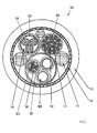
- Fig.3
- einen Querschnitt durch das Sammelkabel von Fig.2;
- Fig.4
- einen Querschnitt durch ein weiteres Sammelkabel;
- Fig.5
- eine schematische Darstellung einer bremszuspanneinrichtungsseitigen Kabel-Steckverbindung;
- Fig.6
- eine schematische Darstellung einer wagenseitigen Kabel-Steckverbindung.
- Fig.1
- a schematic representation of an electromechanical Bremszuspanneinrichtung;
- Fig.2
- a schematic representation of a preferred embodiment of an electrical wiring between a arranged on a car floor terminal box and the Bremszuspanneinrichtung of Figure 1 in the form of a collecting cable;
- Figure 3
- a cross section through the collecting cable of Figure 2;
- Figure 4
- a cross section through another collecting cable;
- Figure 5
- a schematic representation of a brake booster side cable connector;
- Figure 6
- a schematic representation of a car-side cable connector.
Die in Fig. 1 insgesamt mit 1 bezeichnete, bevorzugte Ausführungsform einer
elektromechanischen Bremszuspanneinrichtung bildet eine von mehreren
Bremszuspanneinrichtungen eines Schienenfahrzeugs, beispielsweise einer S-Bahn. Die
Bremszuspanneinrichtung 1 beinhaltet einen Bremsaktuator 2 mit einer
Betriebsbremseinheit und einer Speicherbremseinheit Die Betriebsbremseinheit hat einen
elektrischen Antrieb, beispielsweise einen elektrischen Stellmotor 4, der in einem
Aktuatorgehäuse 6 des Bremsaktuators 2 untergebracht ist. Ein mechanischer
Kraftumsetzer 8 dient zur Umsetzung der vom Bremsaktuator 2 abgegebenen Energie in
eine Bremszuspannbewegung.The designated in Fig. 1 in total with 1, preferred embodiment of a
Electromechanical brake application device forms one of several
Bremszuspanneinrichtungen a rail vehicle, such as a S-Bahn. The
Brake application device 1 includes a brake actuator 2 with a
Service brake unit and a memory brake unit The service brake unit has one
electric drive, for example, an electric servomotor 4, in one
Actuator 6 of the brake actuator 2 is housed. A mechanical one
Der Stellmotor 4 versetzt eine koaxiale Bremsspindel 10 in Drehung, welche durch den
Kraftumsetzer 8 in eine Bremszuspannbewegung von Bremsbelägen 12 in Richtung auf
eine Wellenbremsscheibe 14 gewandelt werden. Der Kraftumsetzer 8 umfaßt unter
anderem eine Mutter-/Spindel-Baueinheit 16 mit einer auf der Bremsspindel 10 drehbar
gelagerten Spindelmutter 18, welche bei Drehung der Bremsspindel 10 Linearbewegungen
in Richtung der Spindelachse 42 ausführen kann. Das vom Stellmotor 4 abgewandte Ende
der Bremsspindel 10 ragt in einen zylindrischen Hohlabschnitt eines Pleuels 20 hinein, der
mit der Spindelmutter 18 dreh und axialfest verbunden ist Außerdem ist der zylindrische
Hohlabschnitt des Pleuels 20 in einer Schiebehülse 22 dreh- und axialfest gehalten, auf
welche wenigstens eine sich am Aktuatorgehäuse 6 abstützende Speicherfeder 24 wirkt
Die Speicherfeder 24 ist Teil der Speicherbremseinheit und dient als Energiespeicher zum
Speichern und Abgeben von Energie zum Zuspannen der Bremse als betriebliche
Notbremse im Sinne einer unterlegten Sicherheitsebene bei Ausfall der
Betriebsbremseinheit und/oder als Park- oder Feststellbremse. Sowohl die Betriebs- als
auch die Speicherbremseinheit wirken auf den Pleuel 20. In Bremslösestellung ist die
Speicherfeder 24 durch eine Verriegelungseinrichtung 26 in der vorgespannten Stellung
gehalten.The servo motor 4 sets a
Ein Pleuelkopf 28 des Pleuels 20 ragt aus der Schiebehülse 22 heraus und ist an einem
Bremshebel 36 mittels eines Gelenks 40 senkrecht zur Spindelachse 42 angelenkt. Bei
Antrieb der Bremsspindel 10 in Bremszuspannrichtung bzw. bei Lösen der
Verriegelungseinrichtung 26 der Speicherfeder 24 wird aufgrund des dann axial
ausfahrenden Pleuels 20 ein Gelenkbolzen des Gelenks 40 unter anderem durch im
wesentlichen senkrecht zur Bolzenachse angreifende Scherkräfte beansprucht.A connecting
Das andere Ende des Bremshebels 36 wirkt auf eine Exzenteranordnung mit einer
Exzenterwelle 46, die an einen Zangenhebel 48 angelenkt ist, der zusammen mit einem
weiteren Zangenhebel 50 eine Bremszange 52 bildet. An den einen Enden der Zangenhebel
48, 50 sind jeweils Belaghalter 54 mit Bremsbelägen 12 angeordnet, die in Richtung der
Achse der Wellenbremsscheibe 14 verschieblich sind. Die von den Bremsbelägen 12
abgewandt liegenden Enden der Zangenhebel 48, 50 sind miteinander über einen
Druckstangensteller 56 verbunden, der vorzugsweise elektrisch betätigt ausgelegt ist. Die
beschriebene Anordnung bildet ebenfalls einen Teil des Kraftumsetzers 8, der die vom
Stellmotor 4 oder von der Speicherfeder 24 veranlaßten Ausfahrbewegungen des Pleuels 20
in eine Bremszuspannbewegung der Bremsbeläge 12 in Richtung auf die Bremsscheibe 14
wandelt.The other end of the
Der Gelenkbolzen des Gelenks 40 wird vorzugsweise durch einen Scherkraftmeßbolzen 58
gebildet. Der Scherkraftmeßbolzen 58 ist mit wenigstens einem aus Maßstabsgründen nicht
dargestellten Meßaufnehmer zur Messung von Größen versehen, aus welchen die an den
Bremsbelägen 12 wirkende Bremskraft mittelbar oder unmittelbar ableitbar ist. In
bevorzugter Ausführungsform wird der Meßaufnehmer durch Dehnmeßstreifen (DMS)
gebildet, die am Umfang des Scherkraftmeßbolzens 58 vorzugsweise durch Klebung derart
befestigt sind, daß sie den aufgrund der gegensinnig wirkenden Scherkräfte
hervorgerufenen Scherverformungen des Scherkraftmeßbolzens 58 proportionale Signale
erzeugen. Anstatt am Scherkraftmeßbolzen 58 oder zusätzlich hierzu können auch ein oder
mehrere Dehnmeßstreifen am Bremshebel 36 angeordnet sein, um aus den Verformungen
des Bremshebels 36 die Bremskräfte ableiten zu können.The hinge pin of the joint 40 is preferably by a
In einer eine DMS-Brückenschaltung beinhaltenden Auswerteelektronik findet eine
Umrechnung der Scherverformungssignale in Signale für die jeweils an den Bremsbelägen
12 wirkende Ist-Zuspannkraft statt, welche über eine Signalleitung 59 an eine Steuer- und
Regeleinrichtung 60 weitergeleitet werden, um anhand eines Soll-Ist-Vergleichs eine
Regeldifferenz zwischen einer Soll-Zuspannkraft und der Ist-Zuspannkraft zu berechnen.
Die Bremskraft-Sollwertvorgabe orientiert sich beispielsweise am Erreichen einer
geforderten Soll-Zuspannkraft in möglichst kurzer Zeit, beispielsweise 75% der maximalen
Zuspannkraft in 0,3 Sekunden.In a transmitter containing a strain gauge bridge circuit finds a
Conversion of shear deformation signals into signals for the
Die Steuer- und Regeleinrichtung 60 steuert ein Leistungsteil 62 an, welches in
Abhängigkeit der berechneten Regeldifferenz einen Betriebsstrom für den Stellmotor 4
aussteuert, der durch einen an eine zwischen dem Leistungsteil 62 und dem Stellmotor 4
verlaufende elektrische Leitung 64 angeschlossenen Stromsensor 66 gemessen wird, wobei
eine Rückmeldung an die Steuer- und Regeleinrichtung 60 durch ein entsprechendes, über
eine Signalleitung 68 rückgeführtes Motorstromsignal erfolgt. Außer zur Einregelung einer
Soll-Zuspannkraft dienen die in die Steuer- und Regeleinrichtung 60 eingesteuerten Signale
für die Ist-Zuspannkräfte und für den jeweiligen Motorstrom zur Überwachung der
Krafteinsteuerung und Funktionsfähigkeit der Bremszuspanneinrichtung 1 bei
sicherheitsrelevanten Bremsungen. Zur Verifizierung der Meßergebnisse kann auch der
antriebsseitig durch den Stromsensor 66 gemessene Motorstrom in der Steuer- und
Regeleinrichtung 60 mit dem Signal für die Ist-Zuspannkraft abgeglichen werden.The control and regulating
Ein in der Motorwicklung des Stellmotors 4 angeordneter Temperatursensor 70 dient zur
Temperaturüberwachung während des Betriebs und liefert über eine Signalleitung 72
entsprechende Signale an die Steuer- und Regeleinrichtung 60. Zusätzlich können weitere
Temperatursensoren zur Temperaturüberwachung von einzelnen oder mehreren
Komponenten der Bremszuspanneinrichtung 1 vorgesehen sein, beispielsweise ein
Temperatursensor zur Messung der Temperatur des Leistungsteils 62. Darüber hinaus kann
auch ein Temperatursensor zur Messung der Umgebungstemperatur Werte an die Steuerund
Regeleinrichtung 60 liefem.An arranged in the motor winding of the servomotor 4
Die Bremszuspanneinrichtung 1 ist vorzugsweise zur Erzeugung von lastkorrigierten
und/oder schlupfgeregelten Bremskräften ausgebildet, wobei unter einer lastkorrigierten
Bremskraft eine im wesentlichen an das jeweils vorliegende Gewicht des
Schienenfahrzeugs angepaßte Bremskraft und unter einer schlupfgeregelten Bremskraft
eine Bremskraft verstanden werden soll, durch welche die Bremsung mit idealem
Radschlupf erfolgt (Gleitschutzregelung). Hierzu weist Steuer- und Regeleinrichtung 60
entsprechende Regelfunktionen auf. Die Steuer- und Regelelektronik 60 ist vorzugsweise in
einem separaten, aus Maßstabsgründen nicht gezeigten Gehäuse untergebracht, welches an
das Aktuatorgehäuse 6 angeflanscht ist Alternativ hierzu könnte die Steuer- und
Regelelektronik 60 aber auch fern der Bremszuspanneinrichtung in einem Wagen der S-Bahn
angeordnet sein.The brake application device 1 is preferably for generating load-corrected
and / or slip-controlled braking forces, wherein under a load-corrected
Braking a substantially to the respective present weight of
Rail vehicle adapted braking force and under a slip-controlled braking force
a braking force is to be understood by which the braking with ideal
Wheel slip occurs (anti-slip control). For this purpose, control and regulating
Wie Fig.2 zeigt, ist die Bremszuspanneinrichtung 1 an einem Drehgestell 74 eines Wagens
76 des Schienenfahrzeugs festgelegt, wobei die Bremsscheibe 14 mit einer am Drehgestell
74 gelagerten Achse 78 drehfest verbunden ist. Das Drehgestell 74 kann Dreh- und
Vertikalbewegungen in Bezug zu einem Wagenkasten 80 des Wagens 76 ausführen. Eine
energie- und/oder signalübertragende Verbindung der Bremszuspanneinrichtung 1 mit
einem wagenkastenseitigen Anschluß 82, der mit zugeordneten Steuer-, Signalgeberund/oder
Energieversorgungseinrichtungen im Wagen 76 oder in einem anderen Wagen in
Kontakt steht, erfolgt durch Bewegungen des Drehgestells 74 tolerierende elektrische
Kabel und/oder Lichtwellenleiter, wie beispielsweise die elektrische Leitung 64 gemäß
Fig.1, welche den Stellmotor 4 mit dem Leistungsteil 62 verbindet. Zumindest zwischen
der Bremszuspanneinrichtung 1 und dem Wagenkasten 80 des Wagens 76 sind sämtliche
elektrischen Kabel und/oder Lichtwellenleiter in einem einzigen Sammelkabel 84
zusammengefaßt, welches mit der Bremszuspanneinrichtung 1 und/oder mit dem
wagenkastenseitigen Anschluß 82 lösbar verbunden ist.As FIG. 2 shows, the brake application device 1 is mounted on a
Vorzugsweise sind beide Enden des Sammelkabels 84 sowohl wagenseitig als auch
bremszuspanneinrichtungsseitig mittels je einer lösbaren Steck- oder Schraubverbindung
86, 88 anschließbar, wobei das Sammelkabel 84 die Entfernung zwischen einem am Boden
des Wagenkastens 76 angeordneten Klemmkasten 82 und einem Gehäuse 90 der
Bremszuspanneinrichtung 1 überbrückt Denkbar ist auch jegliche andere Art von lösbarer
Verbindung. Die wagenseitige Steck- oder Schraubverbindung kann beispielsweise durch
einen Steckverbinder 86 mit Schirmbügel und die bremszuspanneinrichtungsseitige
Steckverbindung durch einen Rundstecker 88 mit Schirmauflage realisiert sein. Wie beim
Sammelkabel 84, so sind auch bei den Steck- oder Schraubverbindungen 86, 88 sämtliche
den einzelnen Kabeln und Leitungen zugeordneten Kontakte in jeweils einem einzigen
Stecker bzw. in einer einzigen Buchse integriert. Alternativ könnte das Sammelkabel 84
auch mittels einer zuggesicherten Kabeldurchführung in das Gehäuse 90 der
Bremszuspanneinrichtung 1 oder in den Klemmkasten 82 münden. Entscheidend ist, daß
mindestens eine lösbare Verbindung 86, 88 für das Sammelkabel 84 vorhanden ist.Preferably, both ends of the collecting
Der Klemmkasten 82 ist mit einer aus Maßstabsgründen nicht dargestellten Klemmenreihe
versehen, in welche Enden von Kabeln und Leitungen münden, welche von den Steuer-,
Signalgeber- und/oder Energieversorgungseinrichtungen hergeführt sind. Die einzelnen
Klemmen der Klemmenreihe sind wiederum mit zugeordneten Kontakten der
wagenseitigen lösbaren Verbindung 86 verbunden. Das Sammelkabel 84 ist länger als die
kürzeste Verbindung zwischen der bremszuspanneinrichtungsseitigen und der
wagenseitigen lösbaren Verbindung 86, 88, um eine ungehinderte Bewegung des
Drehgestells 74 in Bezug zum Wagenkasten 80 zu ermöglichen.The
Das Sammelkabel 84 kann beispielsweise durch Bündelung einzelner, etwa gleich langer Kabel mittels Kabelbinder realisiert sein, wobei die Enden jeweils mit einem männlichen oder weiblichen Steckkontakt versehen sind. Vorzugsweise sind sämtliche Einzelkabel jedoch innerhalb eines einzigen Sammelkabelmantels 91 geführt, wie Fig.3 zeigt, in welcher eine bevorzugte Ausführungsform des Sammelkabels 84 dargestellt ist. Wie bereits erwähnt, dient das Sammelkabel 84 zur Leitung von Lichtwellen und analoger und/oder digitaler Signale, wobei in dem Sammelkabel 84 beispielsweise folgende Einzelkabel oder Einzelleitungen zusammengefaßt sind :
- mehrere Impulsgebersignal-
und Versorgungskabel 92, welche in einer Gruppe mit eigenem Kabelmantel 98 und eigener Abschirmung 99 zusammengefaßt sind, welche Signale eines an der Radnabe angeordneten Impulsgebers zur Drehzahlmessung des Rades sowie die für den Impulsgeber notwendige elektrische Energie übertragen, mehrere Feldbuskabel 94 eines CAN-Busses aus Kupfer, welche in einer Gruppe mit eigenem Kabelmantel 98 und eigener Abschirmung 99 zusammengefaßt sind,Steuerleitungen 96 zum Auslösen von Sicherheits- und Parkbremsungen,mehrere Leitungen 97 zur Leistungsversorgung des Stellmotors mit eigenem Kabelmantel 98 und eigener Abschirmung 99.
- a plurality of pulser signal and
supply cables 92, which are combined in a group with itsown cable sheath 98 and itsown shielding 99, which transmit signals of a arranged on the wheel hub pulse generator for measuring the speed of the wheel and the necessary for the pulse generator electrical energy, - a plurality of
field bus cables 94 of a CAN bus made of copper, which are combined in a group with itsown cable sheath 98 and itsown shielding 99, -
Control lines 96 for triggering safety and parking brakes, -
several lines 97 for power supply of the servo motor with itsown cable sheath 98 and its own shield 99th
Folglich sind gleichartige oder demselben Zweck dienende Kabel und Leitungen 92, 94, 96,
97 vorzugsweise in jeweils einer Gruppe mit eigenem Kabelmantel 98 und teilweise auch mit
eigener Einzelabschirmung 99 innerhalb des Sammelkabelmantels 91 geführt. Der
Sammelkabelmantel 91 ist vorzugsweise faserverstärkt, beispielsweise durch Metall- oder
Karbonfasem, weiterhin ist ein Metallgestrick zur Verstärkung denkbar. Die radial innere
Fläche des Sammelkabelmantels 91 ist mit einer durchgehenden Gesamtabschirmung 100
bedeckt, welche vorzugsweise aus geflochtenem und mit Vlies unterlegtem Abschirmmaterial
besteht. Beispielsweise kann als Abschirmmaterial ein Metallgeflecht und/oder eine elektrisch
leitende Folie verwendet werden.Consequently, similar or the same purpose cables and
Die Gesamtabschirmung 100 umgibt die Einzelabschirmungen 99 und ist von diesen durch
eine oder mehrere Isolationsschichten getrennt, welche beispielsweise durch Luft und/oder ein
anderes Isolationsmaterial und/oder durch die Kabelmäntel 98 der Gruppen 92, 94, 96, 97 von
Kabeln gebildet wird. Weiterhin sind die Einzelabschirmungen 99 vorzugsweise durch die
Kabelmäntel 98 ebenfalls voneinander isoliert Die Steuerleitungen 96 zum Auslösen von
Sicherheits- und Parkbremsungen sind vorzugsweise längs der radial inneren Fläche der
Gesamtabschirmung 100 mit Umfangsabstand angeordnet und umgeben die weiteren Kabel
und Leitungen 92, 94, 97. Die in Fig.1 schematisch dargestellte Steuer- und Regelelektronik
60 ist bevorzugt in einem eigenen, am Gehäuse 90 der Bremszuspanneinrichtung 1
angeflanschten Gehäuse untergebracht Deshalb sind entsprechende Steuerleitungen hier nicht
Bestandteil des Sammelkabels 84.The
Eine weitere Ausrührungsform eines Sammelkabels 102 ist in Fig.4 dargestellt, wobei in dem Sammelkabel 102 folgende Einzelkabel oder Einzelleitungen zusammengefaßt sind :
mehrere Leistungsversorgungskabel 104mit eigenem Kabelmantel 105 und eigener Abschirmung 107,- mehrere Impulsgebersignal-
und Versorgungskabel 106mit eigenem Kabelmantel 105 und eigener Abschirmung 107, Feldbuskabel 108 als Lichtwellenleiter,Steuerleitungen 110 zur Ansteuerung und Versorgung einer elektrischen Hilfslöseeinrichtung sowie Steuerleitungen 112 zum Auslösen von Sicherheits- und Parkbremsungenmit eigenem Kabelmantel 105.
- several
power supply cables 104 with theirown cable sheath 105 andown shielding 107, - several pulser signal and
supply cable 106 with itsown cable sheath 105 and itsown shielding 107, -
Fieldbus cable 108 as optical fiber, -
Control lines 110 for controlling and supplying an electrical auxiliary release device andcontrol lines 112 for triggering safety and parking brakes with their own cable sheath 105th
Für den Fall, daß die Steuer- und Regelelektronik 60 nicht wie bevorzugt am Gehäuse 90
der Bremszuspanneinrichtung 1 angeordnet, sondern fem von dieser beispielsweise in oder
an einem Wagen des Schienenfahrzeugs, vorzugsweise an einem Unterboden des
Wagenskastens angeordnet ist, können in dem Sammelkabel 102 auch die entsprechenden
Steuerleitungen als elektrische Leitungen oder Lichtwellenleiter integriert sein.In the event that the
Um eine kompakte Bauform zu erzielen, sind die Kabel und Leitungen 104, 106, 108, 110,
112 möglichst dicht gepackt, wobei die Zwischenräume mit einem Füllmaterial 114
ausgegossen sind oder Luft enthalten. Für den Sammelkabelmantel 116 und die
Gesamtabschirmung 118 gelten die Ausführungen zu der vorangehend beschriebenen
Ausführungsform. Zum zusätzlichen Schutz gegen mechanische Beschädigung kann der
Sammelkabelmantel 116 einen weiteren Schutzüberzug aufweisen, beispielsweise in Form
eines Schutzschlauches, welcher auch in den Sammelkabelmantel 116 selbst integriert sein
kann. Sämtliche Kabelmäntel 105 und insbesondere der Sammelkabelmantel 116 bestehen
aus einem Material, welches resistent gegenüber hohen Temperaturschwankungen, großen
Verformungen, Schwingungen und Schlagbelastung ist.In order to achieve a compact design, the cables and
Die Gesamtabschirmung 100 des Sammelkabels 84 gemäß der bevorzugten Ausführung ist
mittels des bremszuspanneinrichtungsseitigen Steckverbinders 88 mit der Masse des
Drehgestells 74 elektrisch verbunden. Hierzu ist die Gesamtschirmung 100 an einer
Schirmkabelverschraubung 120 eines Rundsteckers 122 des Steckverbinders 88 flächig
geklemmt, wie aus Fig. 5 hervorgeht Der Rundstecker 122 weist eine Schirmauflage in
Form eines Adapters 124 mit konusförmiger radial innerer Klemmfläche auf, gegen
welchen ein Konusring 126 mit komplementär konisch ausgebildeter Klemmfläche mittels
einer axialen Druckschraube 128 gespannt ist, um ein freigelegtes, nach radial außen
umgebogenes Ende 130 der vorzugsweise aus Metallgeflecht bestehenden
Gesamtabschirmung 100 zwischen den Klemmflächen zu klemmen. Vorzugsweise sind der
Druckschraube 128 und dem Konusring 126 ein Gummiring 132 und eine Scheibe 134
axial zwischengeordnet. Die innerhalb der Gesamtabschirmung 100 verlaufenden
elektrischen Kabel 92, 94, 96, 97 stehen mit nicht gezeigten Steckkontakten des
Rundsteckers 122 in Verbindung. Der Adapter 124, der Konusring 126 und die
Druckschraube 128 bestehen aus einem elektrisch leitfähigem Material und bilden
zusammen die Schirmkabelverschraubung 120. Ein aus Maßstabsgründen in Fig.5 nicht
gezeigter, am Gehäuse 90 der Bremszuspanneinrichtung 1 angeordneter Buchsenkörper
einer Buchse besteht ebenfalls aus elektrisch leitendem Material und ist mit der Masse des
Drehgestells 74 elektrisch leitend verbunden. Folglich gerät bei in die Buchse
eingestecktem oder eingeschraubtem Rundstecker 122 die Schirmkabelverschraubung 120
mit dem Buchsengehäuse in Kontakt, so daß die Gesamtabschirmung 100 des
Sammelkabels 84 durch das Drehgestell 74 geerdet wird. Weiterhin bildet die
Schirmkabelverschraubung 120 und das Buchsengehäuse eine Fortsetzung der
Gesamtabschirmung 100 des Sammelkabels 84. Die Einzelabschirmungen 99 der Gruppen
92, 94, 96, 97 von Kabeln und Leitungen sind jedoch gegenüber der
Schirmkabelverschraubung 120 isoliert.The
Andererseits sind die Einzelabschirmungen 99 der Gruppen 92, 94, 96, 97 von Kabeln und
Leitungen mittels des wagenseitigen Steckverbinders 86 mit der Masse des Wagenkastens
80 elektrisch leitend verbunden. Hierzu ist ein am anderen Ende des Sammelkabels 84
angeordneter Stecker 138 mit einem elektrisch leitenden Schirmkontaktbügel 140
vorgesehen, an welchem die innerhalb des Sammelkabels 84 geführten und endseitig blank
gelegten Einzelabschirmungen 99 durch Klemmschellen 142 geklemmt und mit ihm
dadurch elektrisch leitend verbunden sind, wie Fig.6 zeigt. Hingegen ist die
Gesamtabschirmung 100 gegenüber dem Schirmkontaktbügel 140 isoliert. On the other hand, the
Der Stecker 138 ist in eine komplementäre, am Klemmkasten 82 des Wagenkastens 80
angeordnete Buchse 144 eingesteckt, deren Kontakte mit entsprechenden Klemmen der
Klemmenreihe in Verbindung stehen. Durch den Steckverbinder 86 gerät der
Schirmkontaktbügel 140 mit einem komplementären Schirmkontaktbügel 146 der Buchse
144 in elektrisch leitende Verbindung. Der Schirmkontaktbügel 146 ist seinerseits durch
ein Masseband 148 mit dem Wagenkasten 80 elektrisch verbunden, so daß die
Einzelabschirmungen 99 des Sammelkabels 84 an die Masse des Wagenkastens 80 gelegt
sind.The
Anstatt die Gesamtabschirmung 100 an die Masse des Drehgestells 74 und die
Einzelabschirmungen 99 an die Masse des Wagenkastens 80 zu legen, kann auch eine
umgekehrte Zuordnung erfolgen, d.h. daß die Gesamtabschirmung 100 an die Masse des
Wagenkastens 80 und die Einzelabschirmungen 99 an die Masse des Drehgestells 74
angeschlossen werden. Entscheidend ist, daß die Gesamtabschirmung 100 die
Einzelabschirmungen 99 zumindest teilweise umgibt und gegenüber diesen elektrisch
isoliert ist. Instead of the
- 11
- Bremszuspanneinrichtungbrake application
- 22
- Bremsaktuatorbrake actuator
- 44
- Stellmotorservomotor
- 66
- Aktuatorgehäuseactuator housing
- 88th
- Kraftumsetzerpower converter
- 1010
- Bremsspindelbrake spindle
- 1212
- Bremsbelagbrake lining
- 1414
- Bremsscheibebrake disc
- 1616
- Mutter-/Spindel-BaueinheitParent / spindle assembly
- 1818
- Spindelmutterspindle nut
- 2020
- Pleuelpleuel
- 2222
- Schiebehülsesliding sleeve
- 2424
- Speicherfederstorage spring
- 2626
- Verriegelungseinrichtunglocking device
- 2828
- Pleuelkopfsmall end
- 3636
- Bremshebelbrake lever
- 4040
- Gelenkjoint
- 4242
- Spindelachsespindle axis
- 4646
- Exzenterwelleeccentric shaft
- 4848
- Zangenhebelcaliper lever
- 5050
- Zangenhebelcaliper lever
- 5252
- Bremszangecaliper
- 5454
- Belaghalterpad holders
- 5656
- DruckstangenstellerPlunger rod adjuster
- 5858
- Scherkraftmeßbolzenshearing force measuring
- 5959
- Signalleitungsignal line
- 6060
- Steuer- und RegeleinrichtungControl and regulating device
- 6262
- Leistungsteilpower unit
- 6464
- elektrische Leitung electrical line
- 6666
- Stromsensorcurrent sensor
- 6868
- Signalleitungsignal line
- 7070
- Temperatursensortemperature sensor
- 7272
- Signalleitungsignal line
- 7474
- Drehgestellbogie
- 7676
- Wagendare
- 7878
- Achseaxis
- 8080
- Wagenkastencar body
- 8282
- Klemmkastenterminal box
- 8484
- Sammelkabeltrunk cable
- 8686
- SteckverbinderConnectors
- 8888
- SteckverbinderConnectors
- 9090
- Gehäusecasing
- 9191
- SammelkabelmantelCommon cable sheath
- 9292
- Impulsgebersignal- und VersorgungskabelPulse generator signal and supply cable
- 9494
- Feldbuskabelfieldbus
- 9696
- Steuerleitungencontrol lines
- 9797
- Leitungencables
- 9898
- Kabelmantelcable sheath
- 9999
- Abschirmungshielding
- 100100
- Gesamtabschirmungtotal screening
- 102102
- Sammelkabeltrunk cable
- 104104
- LeistungsversorgungskabelPower supply cable
- 105105
- Kabelmantelcable sheath
- 106106
- Impulsgeber- und VersorgungskabelPulse and supply cable
- 107107
- Abschirmungshielding
- 108108
- Feldbuskabelfieldbus
- 110110
- Steuerleitungencontrol lines
- 112112
- Steuerleitungencontrol lines
- 114114
- Füllmaterialfilling material
- 116116
- Sammelkabelmantel Common cable sheath
- 118118
- Gesamtabschirmungtotal screening
- 120120
- SchirmkabelverschraubungSchirmkabelverschraubung
- 122122
- Rundsteckerround plug
- 124124
- Adapteradapter
- 126126
- Konusringcone ring
- 128128
- Druckschraubepressure screw
- 130130
- EndeThe End
- 132132
- Gummiringrubber ring
- 134134
- Scheibedisc
- 138138
- Steckerplug
- 140140
- SchirmkontaktbügelScreen contact bow
- 142142
- Klemmschellenclamps
- 144144
- BuchseRifle
- 146146
- SchirmkontaktbügelScreen contact bow
- 148148
- Massebandground strap
Claims (12)
Applications Claiming Priority (2)
| Application Number | Priority Date | Filing Date | Title |
|---|---|---|---|
| DE10239695A DE10239695C1 (en) | 2002-08-29 | 2002-08-29 | Electrical cabling for rail vehicle electrics has individually screened electrical cables housed in common cable provided with overall screening |
| DE10239695 | 2002-08-29 |
Publications (2)
| Publication Number | Publication Date |
|---|---|
| EP1393984A1 true EP1393984A1 (en) | 2004-03-03 |
| EP1393984B1 EP1393984B1 (en) | 2007-01-17 |
Family
ID=29225197
Family Applications (1)
| Application Number | Title | Priority Date | Filing Date |
|---|---|---|---|
| EP03018779A Expired - Lifetime EP1393984B1 (en) | 2002-08-29 | 2003-08-28 | Electric wiring of a vehicle |
Country Status (2)
| Country | Link |
|---|---|
| EP (1) | EP1393984B1 (en) |
| DE (2) | DE10239695C1 (en) |
Cited By (3)
| Publication number | Priority date | Publication date | Assignee | Title |
|---|---|---|---|---|
| CN101155701B (en) * | 2005-12-22 | 2010-09-29 | 塞夫·霍兰德有限公司 | Wheel hub arrangement |
| US20210241936A1 (en) * | 2020-02-04 | 2021-08-05 | Structured Home Wiring Direct, LLC | Composite Hybrid Cables and Methods of Manufacturing and Installing the Same |
| EP3971918A4 (en) * | 2019-05-16 | 2023-05-17 | LS Cable & System Ltd. | Composite cable for vehicle and composite cable assembly including same |
Families Citing this family (4)
| Publication number | Priority date | Publication date | Assignee | Title |
|---|---|---|---|---|
| JP4577605B2 (en) * | 2004-07-30 | 2010-11-10 | 日立オートモティブシステムズ株式会社 | Electric disc brake |
| CN101479813B (en) * | 2005-08-15 | 2012-06-06 | 辉固地质组股份公司 | Generic tow lead-in for streamers |
| US7432446B2 (en) * | 2005-09-28 | 2008-10-07 | Symbol Technologies, Inc. | Coiled electronic article surveillance (EAS) cable |
| DE102014109269B4 (en) * | 2014-07-02 | 2021-04-08 | Lisa Dräxlmaier GmbH | Energy supply system for a motor vehicle |
Citations (5)
| Publication number | Priority date | Publication date | Assignee | Title |
|---|---|---|---|---|
| GB502122A (en) * | 1937-10-19 | 1939-03-13 | Western Electric Co | Improvements in electric cables having shielded conductors |
| WO1994020968A1 (en) * | 1993-03-04 | 1994-09-15 | Aeg Schienenfahrzeuge Gmbh | Electromagnetically shielded cable or line |
| EP0685239A2 (en) * | 1994-06-03 | 1995-12-06 | Siemens Medical Systems, Inc. | Flexible multi-parameter cable |
| WO2001091137A2 (en) * | 2000-05-19 | 2001-11-29 | Spirent Communications | Multiple shielded cable |
| US20010054123A1 (en) * | 1996-09-16 | 2001-12-20 | Gregory K. Henrikson | Ieee 1394 active wall disconnect and aircraft qualified cable |
Family Cites Families (1)
| Publication number | Priority date | Publication date | Assignee | Title |
|---|---|---|---|---|
| DE19945701A1 (en) * | 1999-09-23 | 2001-04-19 | Knorr Bremse Systeme | Brake actuator |
-
2002
- 2002-08-29 DE DE10239695A patent/DE10239695C1/en not_active Revoked
-
2003
- 2003-08-28 DE DE50306293T patent/DE50306293D1/en not_active Expired - Lifetime
- 2003-08-28 EP EP03018779A patent/EP1393984B1/en not_active Expired - Lifetime
Patent Citations (5)
| Publication number | Priority date | Publication date | Assignee | Title |
|---|---|---|---|---|
| GB502122A (en) * | 1937-10-19 | 1939-03-13 | Western Electric Co | Improvements in electric cables having shielded conductors |
| WO1994020968A1 (en) * | 1993-03-04 | 1994-09-15 | Aeg Schienenfahrzeuge Gmbh | Electromagnetically shielded cable or line |
| EP0685239A2 (en) * | 1994-06-03 | 1995-12-06 | Siemens Medical Systems, Inc. | Flexible multi-parameter cable |
| US20010054123A1 (en) * | 1996-09-16 | 2001-12-20 | Gregory K. Henrikson | Ieee 1394 active wall disconnect and aircraft qualified cable |
| WO2001091137A2 (en) * | 2000-05-19 | 2001-11-29 | Spirent Communications | Multiple shielded cable |
Cited By (5)
| Publication number | Priority date | Publication date | Assignee | Title |
|---|---|---|---|---|
| CN101155701B (en) * | 2005-12-22 | 2010-09-29 | 塞夫·霍兰德有限公司 | Wheel hub arrangement |
| EP3971918A4 (en) * | 2019-05-16 | 2023-05-17 | LS Cable & System Ltd. | Composite cable for vehicle and composite cable assembly including same |
| US11955255B2 (en) | 2019-05-16 | 2024-04-09 | Ls Cable & System Ltd. | Composite cable for vehicle and composite cable assembly including same |
| US20210241936A1 (en) * | 2020-02-04 | 2021-08-05 | Structured Home Wiring Direct, LLC | Composite Hybrid Cables and Methods of Manufacturing and Installing the Same |
| US11823817B2 (en) * | 2020-02-04 | 2023-11-21 | Structured Home Wiring Direct, LLC | Composite hybrid cables and methods of manufacturing and installing the same |
Also Published As
| Publication number | Publication date |
|---|---|
| DE50306293D1 (en) | 2007-03-08 |
| EP1393984B1 (en) | 2007-01-17 |
| DE10239695C1 (en) | 2003-11-13 |
Similar Documents
| Publication | Publication Date | Title |
|---|---|---|
| DE102010025475A1 (en) | Control system of an aircraft with a valve | |
| WO2008119477A2 (en) | Motor arrangement | |
| EP2280263A2 (en) | Supporting load measuring device and retrofitting method for a vehicle trailer device | |
| DE102019107608A1 (en) | composite cable | |
| EP2423068A1 (en) | Earthing contact | |
| AT512846B1 (en) | Method and device for pantograph failure monitoring | |
| EP1148266A1 (en) | Apparatus and process to monitor the temperature of brake discs | |
| EP1393984B1 (en) | Electric wiring of a vehicle | |
| EP3509923B1 (en) | Multi-part closed-loop brake controller | |
| DE10239696B3 (en) | Device for connecting an electromechanical brake application device of a rail vehicle brake with associated control, signaling and / or energy supply devices | |
| EP1726473B1 (en) | Force measuring device and method for determining a transversal force | |
| DE102018204184A1 (en) | Method for monitoring a supply system of a robot | |
| DE102019107581A1 (en) | composite cable | |
| EP0743528B1 (en) | Mains voltage measuring appliance for track vehicles | |
| DE10347115B3 (en) | Brake operating device for rail carriage brake has electromechanical brake actuator contained in actuator housing ventilated via at least one air line | |
| DE102012015357A1 (en) | Non-shiftable clutch with torque monitoring | |
| DE102013202800A1 (en) | Wheel device for use as e.g. alternator, in car, has energy conversion element to convert mechanical energy into electrical energy in operating condition, where conversion element includes smart material designed as electroactive polymer | |
| EP1726472B1 (en) | Force measuring device and method for determining a contact force | |
| EP2238367B1 (en) | Brake system for a vehicle | |
| DE102010024738A1 (en) | Steering gear i.e. electromechanical steering gear, for passenger motor car, has interconnection formed as wireless plug connections between control device and rotational torque measurement unit and between control device and electromotor | |
| EP3461662A1 (en) | Damping device | |
| DE10106374C2 (en) | Method for reducing the operating temperature of electromechanical brake application devices of a vehicle brake | |
| DE102010044991A1 (en) | Method for transferring data between environment sensors for detecting motor car-external objects, involves transmitting data with different information between environment sensors and control device over respective electric lines | |
| EP0850400A1 (en) | Compression-tension transducer, especially for electromechanical braking systems | |
| DE102010001521A1 (en) | position Steller |
Legal Events
| Date | Code | Title | Description |
|---|---|---|---|
| PUAI | Public reference made under article 153(3) epc to a published international application that has entered the european phase |
Free format text: ORIGINAL CODE: 0009012 |
|
| AK | Designated contracting states |
Kind code of ref document: A1 Designated state(s): AT BE BG CH CY CZ DE DK EE ES FI FR GB GR HU IE IT LI LU MC NL PT RO SE SI SK TR |
|
| AX | Request for extension of the european patent |
Extension state: AL LT LV MK |
|
| 17P | Request for examination filed |
Effective date: 20040903 |
|
| AKX | Designation fees paid |
Designated state(s): AT BE BG CH CY CZ DE DK EE ES FI FR GB GR HU IE IT LI LU MC NL PT RO SE SI SK TR |
|
| 17Q | First examination report despatched |
Effective date: 20041116 |
|
| GRAP | Despatch of communication of intention to grant a patent |
Free format text: ORIGINAL CODE: EPIDOSNIGR1 |
|
| GRAS | Grant fee paid |
Free format text: ORIGINAL CODE: EPIDOSNIGR3 |
|
| GRAA | (expected) grant |
Free format text: ORIGINAL CODE: 0009210 |
|
| AK | Designated contracting states |
Kind code of ref document: B1 Designated state(s): AT BE BG CH CY CZ DE DK EE ES FI FR GB GR HU IE IT LI LU MC NL PT RO SE SI SK TR |
|
| PG25 | Lapsed in a contracting state [announced via postgrant information from national office to epo] |
Ref country code: DK Free format text: LAPSE BECAUSE OF FAILURE TO SUBMIT A TRANSLATION OF THE DESCRIPTION OR TO PAY THE FEE WITHIN THE PRESCRIBED TIME-LIMIT Effective date: 20070117 Ref country code: FI Free format text: LAPSE BECAUSE OF FAILURE TO SUBMIT A TRANSLATION OF THE DESCRIPTION OR TO PAY THE FEE WITHIN THE PRESCRIBED TIME-LIMIT Effective date: 20070117 Ref country code: IE Free format text: LAPSE BECAUSE OF FAILURE TO SUBMIT A TRANSLATION OF THE DESCRIPTION OR TO PAY THE FEE WITHIN THE PRESCRIBED TIME-LIMIT Effective date: 20070117 Ref country code: SI Free format text: LAPSE BECAUSE OF FAILURE TO SUBMIT A TRANSLATION OF THE DESCRIPTION OR TO PAY THE FEE WITHIN THE PRESCRIBED TIME-LIMIT Effective date: 20070117 Ref country code: NL Free format text: LAPSE BECAUSE OF FAILURE TO SUBMIT A TRANSLATION OF THE DESCRIPTION OR TO PAY THE FEE WITHIN THE PRESCRIBED TIME-LIMIT Effective date: 20070117 |
|
| REG | Reference to a national code |
Ref country code: GB Ref legal event code: FG4D Free format text: NOT ENGLISH |
|
| REG | Reference to a national code |
Ref country code: CH Ref legal event code: EP Ref country code: CH Ref legal event code: NV Representative=s name: ISLER & PEDRAZZINI AG |
|
| REG | Reference to a national code |
Ref country code: SE Ref legal event code: TRGR |
|
| GBT | Gb: translation of ep patent filed (gb section 77(6)(a)/1977) |
Effective date: 20070202 |
|
| REG | Reference to a national code |
Ref country code: IE Ref legal event code: FG4D Free format text: LANGUAGE OF EP DOCUMENT: GERMAN |
|
| REF | Corresponds to: |
Ref document number: 50306293 Country of ref document: DE Date of ref document: 20070308 Kind code of ref document: P |
|
| PG25 | Lapsed in a contracting state [announced via postgrant information from national office to epo] |
Ref country code: BG Free format text: LAPSE BECAUSE OF EXPIRATION OF PROTECTION Effective date: 20070418 |
|
| PG25 | Lapsed in a contracting state [announced via postgrant information from national office to epo] |
Ref country code: ES Free format text: LAPSE BECAUSE OF FAILURE TO SUBMIT A TRANSLATION OF THE DESCRIPTION OR TO PAY THE FEE WITHIN THE PRESCRIBED TIME-LIMIT Effective date: 20070428 |
|
| PG25 | Lapsed in a contracting state [announced via postgrant information from national office to epo] |
Ref country code: PT Free format text: LAPSE BECAUSE OF FAILURE TO SUBMIT A TRANSLATION OF THE DESCRIPTION OR TO PAY THE FEE WITHIN THE PRESCRIBED TIME-LIMIT Effective date: 20070618 |
|
| NLV1 | Nl: lapsed or annulled due to failure to fulfill the requirements of art. 29p and 29m of the patents act | ||
| ET | Fr: translation filed | ||
| REG | Reference to a national code |
Ref country code: IE Ref legal event code: FD4D |
|
| REG | Reference to a national code |
Ref country code: CH Ref legal event code: PCAR Free format text: ISLER & PEDRAZZINI AG;POSTFACH 1772;8027 ZUERICH (CH) |
|
| PLBI | Opposition filed |
Free format text: ORIGINAL CODE: 0009260 |
|
| PLAX | Notice of opposition and request to file observation + time limit sent |
Free format text: ORIGINAL CODE: EPIDOSNOBS2 |
|
| PG25 | Lapsed in a contracting state [announced via postgrant information from national office to epo] |
Ref country code: SK Free format text: LAPSE BECAUSE OF FAILURE TO SUBMIT A TRANSLATION OF THE DESCRIPTION OR TO PAY THE FEE WITHIN THE PRESCRIBED TIME-LIMIT Effective date: 20070117 |
|
| 26 | Opposition filed |
Opponent name: DEUTSCHE BAHN AG PATENTABTEILUNG Effective date: 20071017 |
|
| PG25 | Lapsed in a contracting state [announced via postgrant information from national office to epo] |
Ref country code: CZ Free format text: LAPSE BECAUSE OF FAILURE TO SUBMIT A TRANSLATION OF THE DESCRIPTION OR TO PAY THE FEE WITHIN THE PRESCRIBED TIME-LIMIT Effective date: 20070117 Ref country code: RO Free format text: LAPSE BECAUSE OF FAILURE TO SUBMIT A TRANSLATION OF THE DESCRIPTION OR TO PAY THE FEE WITHIN THE PRESCRIBED TIME-LIMIT Effective date: 20070117 |
|
| BERE | Be: lapsed |
Owner name: KNORR-BREMSE SYSTEME FUR SCHIENENFAHRZEUGE G.M.B. Effective date: 20070831 |
|
| PLBB | Reply of patent proprietor to notice(s) of opposition received |
Free format text: ORIGINAL CODE: EPIDOSNOBS3 |
|
| PG25 | Lapsed in a contracting state [announced via postgrant information from national office to epo] |
Ref country code: MC Free format text: LAPSE BECAUSE OF NON-PAYMENT OF DUE FEES Effective date: 20070831 Ref country code: GR Free format text: LAPSE BECAUSE OF FAILURE TO SUBMIT A TRANSLATION OF THE DESCRIPTION OR TO PAY THE FEE WITHIN THE PRESCRIBED TIME-LIMIT Effective date: 20070418 |
|
| PG25 | Lapsed in a contracting state [announced via postgrant information from national office to epo] |
Ref country code: BE Free format text: LAPSE BECAUSE OF NON-PAYMENT OF DUE FEES Effective date: 20070831 |
|
| PG25 | Lapsed in a contracting state [announced via postgrant information from national office to epo] |
Ref country code: EE Free format text: LAPSE BECAUSE OF FAILURE TO SUBMIT A TRANSLATION OF THE DESCRIPTION OR TO PAY THE FEE WITHIN THE PRESCRIBED TIME-LIMIT Effective date: 20070117 |
|
| PG25 | Lapsed in a contracting state [announced via postgrant information from national office to epo] |
Ref country code: CY Free format text: LAPSE BECAUSE OF FAILURE TO SUBMIT A TRANSLATION OF THE DESCRIPTION OR TO PAY THE FEE WITHIN THE PRESCRIBED TIME-LIMIT Effective date: 20070117 |
|
| PG25 | Lapsed in a contracting state [announced via postgrant information from national office to epo] |
Ref country code: LU Free format text: LAPSE BECAUSE OF NON-PAYMENT OF DUE FEES Effective date: 20070828 |
|
| PG25 | Lapsed in a contracting state [announced via postgrant information from national office to epo] |
Ref country code: TR Free format text: LAPSE BECAUSE OF FAILURE TO SUBMIT A TRANSLATION OF THE DESCRIPTION OR TO PAY THE FEE WITHIN THE PRESCRIBED TIME-LIMIT Effective date: 20070117 Ref country code: HU Free format text: LAPSE BECAUSE OF FAILURE TO SUBMIT A TRANSLATION OF THE DESCRIPTION OR TO PAY THE FEE WITHIN THE PRESCRIBED TIME-LIMIT Effective date: 20070718 |
|
| PLCK | Communication despatched that opposition was rejected |
Free format text: ORIGINAL CODE: EPIDOSNREJ1 |
|
| PLBN | Opposition rejected |
Free format text: ORIGINAL CODE: 0009273 |
|
| STAA | Information on the status of an ep patent application or granted ep patent |
Free format text: STATUS: OPPOSITION REJECTED |
|
| 27O | Opposition rejected |
Effective date: 20091006 |
|
| REG | Reference to a national code |
Ref country code: FR Ref legal event code: PLFP Year of fee payment: 13 |
|
| PGFP | Annual fee paid to national office [announced via postgrant information from national office to epo] |
Ref country code: CH Payment date: 20150824 Year of fee payment: 13 Ref country code: GB Payment date: 20150824 Year of fee payment: 13 |
|
| PGFP | Annual fee paid to national office [announced via postgrant information from national office to epo] |
Ref country code: SE Payment date: 20150824 Year of fee payment: 13 Ref country code: FR Payment date: 20150824 Year of fee payment: 13 |
|
| PGFP | Annual fee paid to national office [announced via postgrant information from national office to epo] |
Ref country code: IT Payment date: 20150827 Year of fee payment: 13 |
|
| PGFP | Annual fee paid to national office [announced via postgrant information from national office to epo] |
Ref country code: AT Payment date: 20160822 Year of fee payment: 14 |
|
| REG | Reference to a national code |
Ref country code: SE Ref legal event code: EUG |
|
| REG | Reference to a national code |
Ref country code: CH Ref legal event code: PL |
|
| GBPC | Gb: european patent ceased through non-payment of renewal fee |
Effective date: 20160828 |
|
| PG25 | Lapsed in a contracting state [announced via postgrant information from national office to epo] |
Ref country code: CH Free format text: LAPSE BECAUSE OF NON-PAYMENT OF DUE FEES Effective date: 20160831 Ref country code: SE Free format text: LAPSE BECAUSE OF NON-PAYMENT OF DUE FEES Effective date: 20160829 Ref country code: LI Free format text: LAPSE BECAUSE OF NON-PAYMENT OF DUE FEES Effective date: 20160831 |
|
| REG | Reference to a national code |
Ref country code: FR Ref legal event code: ST Effective date: 20170428 |
|
| PG25 | Lapsed in a contracting state [announced via postgrant information from national office to epo] |
Ref country code: FR Free format text: LAPSE BECAUSE OF NON-PAYMENT OF DUE FEES Effective date: 20160831 Ref country code: GB Free format text: LAPSE BECAUSE OF NON-PAYMENT OF DUE FEES Effective date: 20160828 |
|
| PG25 | Lapsed in a contracting state [announced via postgrant information from national office to epo] |
Ref country code: IT Free format text: LAPSE BECAUSE OF NON-PAYMENT OF DUE FEES Effective date: 20160828 |
|
| REG | Reference to a national code |
Ref country code: AT Ref legal event code: MM01 Ref document number: 351770 Country of ref document: AT Kind code of ref document: T Effective date: 20170828 |
|
| PG25 | Lapsed in a contracting state [announced via postgrant information from national office to epo] |
Ref country code: AT Free format text: LAPSE BECAUSE OF NON-PAYMENT OF DUE FEES Effective date: 20170828 |
|
| PGFP | Annual fee paid to national office [announced via postgrant information from national office to epo] |
Ref country code: DE Payment date: 20190822 Year of fee payment: 17 |
|
| REG | Reference to a national code |
Ref country code: DE Ref legal event code: R119 Ref document number: 50306293 Country of ref document: DE |
|
| PG25 | Lapsed in a contracting state [announced via postgrant information from national office to epo] |
Ref country code: DE Free format text: LAPSE BECAUSE OF NON-PAYMENT OF DUE FEES Effective date: 20210302 |