EP4126630B1 - Betriebsbremszylinder mit bremszustandserfassung und verfahren zum erfassen eines bremszustands eines betriebsbremszylinders - Google Patents
Betriebsbremszylinder mit bremszustandserfassung und verfahren zum erfassen eines bremszustands eines betriebsbremszylinders Download PDFInfo
- Publication number
- EP4126630B1 EP4126630B1 EP21709390.5A EP21709390A EP4126630B1 EP 4126630 B1 EP4126630 B1 EP 4126630B1 EP 21709390 A EP21709390 A EP 21709390A EP 4126630 B1 EP4126630 B1 EP 4126630B1
- Authority
- EP
- European Patent Office
- Prior art keywords
- state
- sensor
- brake
- brake cylinder
- service brake
- Prior art date
- Legal status (The legal status is an assumption and is not a legal conclusion. Google has not performed a legal analysis and makes no representation as to the accuracy of the status listed.)
- Active
Links
Images

Classifications
-
- F—MECHANICAL ENGINEERING; LIGHTING; HEATING; WEAPONS; BLASTING
- F16—ENGINEERING ELEMENTS AND UNITS; GENERAL MEASURES FOR PRODUCING AND MAINTAINING EFFECTIVE FUNCTIONING OF MACHINES OR INSTALLATIONS; THERMAL INSULATION IN GENERAL
- F16D—COUPLINGS FOR TRANSMITTING ROTATION; CLUTCHES; BRAKES
- F16D49/00—Brakes with a braking member co-operating with the periphery of a drum, wheel-rim, or the like
-
- F—MECHANICAL ENGINEERING; LIGHTING; HEATING; WEAPONS; BLASTING
- F16—ENGINEERING ELEMENTS AND UNITS; GENERAL MEASURES FOR PRODUCING AND MAINTAINING EFFECTIVE FUNCTIONING OF MACHINES OR INSTALLATIONS; THERMAL INSULATION IN GENERAL
- F16D—COUPLINGS FOR TRANSMITTING ROTATION; CLUTCHES; BRAKES
- F16D65/00—Parts or details
- F16D65/14—Actuating mechanisms for brakes; Means for initiating operation at a predetermined position
- F16D65/28—Actuating mechanisms for brakes; Means for initiating operation at a predetermined position arranged apart from the brake
-
- F—MECHANICAL ENGINEERING; LIGHTING; HEATING; WEAPONS; BLASTING
- F16—ENGINEERING ELEMENTS AND UNITS; GENERAL MEASURES FOR PRODUCING AND MAINTAINING EFFECTIVE FUNCTIONING OF MACHINES OR INSTALLATIONS; THERMAL INSULATION IN GENERAL
- F16D—COUPLINGS FOR TRANSMITTING ROTATION; CLUTCHES; BRAKES
- F16D66/00—Arrangements for monitoring working conditions, e.g. wear, temperature
- F16D2066/003—Position, angle or speed
Definitions
- the invention relates to a service brake cylinder, in particular a block brake, with brake state detection, in particular for a rail vehicle, according to the preamble of claim 1.
- the invention also relates to a method for detecting a brake state of a service brake cylinder, in particular a block brake.
- a block brake also called a tread brake
- a tread brake is very often used in rail vehicles as a friction brake in freight vehicles, because it is simply constructed and the brake blocks with their friction lining use the wheel tread of the wheel to be braked as a friction surface.
- the brake pads and wheels wear out during daily operation.
- the condition of the brake i.e. the brake pads, must be checked regularly for safety reasons.
- the current inspection procedure is regular visual inspection and testing with a tool, e.g. a hammer, with the brake pads applied and released by the maintenance staff. This is costly and requires well-trained maintenance staff.
- WO 2015/135074 A1 describes a brake setting monitoring device for a pneumatic brake system, which comprises a contactless proximity sensor which is mounted on a wall of a brake chamber in order to generate a signal when the rear plate of the push rod comes within the detection distance of the proximity sensor. It is seen as a disadvantage that the proximity sensor protrudes into the brake chamber through an opening made in the housing of the brake chamber with one part and with another part which has an electrical connection with cable protrudes outwards into the environment and is exposed to the environmental conditions.
- the object of the invention is to provide a generic service brake cylinder, in particular a block brake, with improved brake condition detection while simultaneously reducing costs and components.
- a service brake cylinder in particular a block brake, comprises a housing with a spindle and a brake state detection device for detecting an application state and a release state of the service brake cylinder.
- the brake state detection device is arranged completely within an interior of the service brake cylinder, enclosed by the housing, and detects the position of the spindle.
- the brake state detection device provides information about the piston position.
- Such a brake state detection device is advantageous not only because it increases the level of safety compared to the currently established manual check, but also because it offers a simple structure.
- a particular advantage is that the brake state detection device in the interior of the housing of the service brake cylinder is completely surrounded by the housing and is well protected from the effects of the weather and damage.
- the brake state detection device can be accessed from the outside in the event of maintenance, e.g. through a resealable maintenance opening.
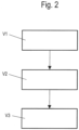
- a method for detecting a brake state of the above-mentioned service brake cylinder comprises the method steps (V1) providing a brake state detection device and arranging the brake state detection device within the service brake cylinder and supplying at least one sensor of the brake state detection device with electrical energy; (V2) generating at least one electrical signal as a brake state signal depending on a brake state, namely application state and/or release state, by the sensor; and (V3) outputting a detected brake state as an application state or release state of the service brake cylinder based on the brake state signals thus detected.
- the detected states i.e. application state and release state
- the operator can use the data to monitor the release or brake actuation state of the brake.
- a particular advantage is that this recorded data is essential in tunnels (e.g. subways or long train tunnels) or in automatic/autonomous operation to avoid incorrect brake application, which can lead to unexpected smoke in a poorly ventilated area.
- potential sources of fire can be detected early enough and prevented.
- the brake state detection device detects the position of a pressure ring or a spindle housing which are connected to the spindle.
- existing functional components or sections thereof can advantageously be used directly or indirectly to detect the position of the spindle and thus the state of the service brake cylinder.
- the brake state detection device has at least one sensor which is arranged in an interior section of the housing of the service brake cylinder between a front wall and a projection of the spindle housing.
- the brake state detection device has at least one sensor which is arranged in an interior section of the housing of the service brake cylinder between a front wall and a projection of the spindle housing.
- the at least one sensor is attached to a holder by means of a fastening section, wherein an axial position of the at least one sensor on the holder can be adjusted.
- the holder can also be designed to accommodate more than one sensor. This is advantageous if an additional sensor is used for plausibility checks.
- the at least one sensor interacts with the projection of the spindle housing in such a way that the at least one sensor is activated in the applied state (A) of the service brake cylinder depending on the position of the projection of the spindle housing and is not activated in the released state (L) of the service brake cylinder.
- the at least one sensor is designed as an inductive proximity sensor or proximity switch.
- Such components are available on the market in a suitable design at low cost and in high quality.
- the at least one sensor can be a contact and/or contactless sensor.
- the at least one brake state signal generated by the at least one sensor is checked for plausibility using at least one further brake state signal generated by at least one further sensor.
- This further sensor can, for example, be attached to the same bracket. However, it is also possible for the further sensor to be arranged at a different location in the housing of the service brake cylinder and to detect the release state, with the first sensor detecting the application state.
- a further embodiment of the method according to the invention provides that the braking states (A, L) output in method step (V3) as the application state (A) or release state (L) of the service brake cylinder are assigned to signals for applying and/or releasing the service brake cylinder of a higher-level brake control system, and an alarm is issued if no application state (A) is detected after receiving a signal to apply the service brake cylinder, and/or if no release state (L) is detected after receiving a signal to release the service brake cylinder.
- This is advantageous because it enables simple and effective detection of non-released brake pads in the release state and of non-applied brake pads in the applied state.
- Figure 1 shows a schematic sectional view of a service brake cylinder 1 according to the invention with a brake state detection device 10.
- the service brake cylinder 1 is designed as a service brake cylinder 1 of a so-called block brake, which is also referred to as a tread brake.
- the braking device 1 is a disk brake, which is not shown here but is conceivable.
- the service brake cylinder 1 comprises a housing 2, a spindle 5, a pressure ring 7 and a spindle housing 8.
- the generally known structure, the function of the service brake cylinder 4 and the interaction with brake rods, brake calipers and/or brake pads are not described in further detail here.
- the housing 2 of the service brake cylinder 1 has a rear wall 2a and a front wall 2b opposite it.
- a surrounding housing wall 2c connects the closed rear wall 2a and the front wall 2b.
- a The interior space 3 of the housing 2 is defined by the rear wall 2a, the front wall 2b and the housing wall 2c.
- the spindle 5 is arranged between the rear wall 2a and the front wall 2b so as to be displaceable in a direction of movement x which runs in the spindle 5.
- the spindle 5 is connected to a service brake piston (not shown), with a brake block shoe 6 being attached to an end of the spindle 5 which protrudes through the front wall 2b.
- the brake block shoe 6 is connected to a brake pad/brake block (not shown). The brake pad interacts with a wheel to be braked (also not shown but easy to imagine) during braking operations.
- the pressure ring 7 and the spindle housing 8 are arranged around the spindle 5 and coupled to it in a manner not described in detail.
- the spindle housing 8 has a radial projection 9 in the form of a flange section. This projection 9 defines a section of the interior 3 between itself, the front wall 2b, housing wall 2c and an outside of the spindle housing 8.
- the brake i.e. the service brake cylinder 1
- the brake has two basic states, namely the application state A and the release state L.
- the spindle 5 in the service brake cylinder 1 moves together with the pressure ring 7 and the spindle housing 8 in the direction of the spindle 5 in the positive direction of movement x, and thus the brake block/brake lining is also pressed onto the wheel to be braked for a braking operation.
- a distance between the projection 9 of the spindle housing 8 and the rear wall 2a of the housing 2 of the service brake cylinder 2 is increased.
- a distance between the projection 9 of the spindle housing 8 and the front wall 2a of the housing 2 is reduced.
- the brake or the service brake cylinder 1 assumes the application state A. In this case, the spindle 5 with its end connected to the brake block 6 is moved out of the housing 2 by a certain amount.
- the arrangement of the braking state detection device 10 is selected such that the braking state detection device 10 can interact with a component movable in the direction of the spindle 5 in order to detect either the release state L, the application state A or both states.
- a suitable component for monitoring the two states is the pressure ring 7 and/or the spindle housing 8, since these components are moved along with the movement of the spindle 5 when the brake is applied and released.
- the brake state detection device 10 here comprises a sensor 11 within the housing 2 of the service brake cylinder 2 in the interior 3.
- the brake state detection device 10 is arranged here in the interior 3 of the housing 2 inside the housing 2 of the service brake cylinder 1.
- the sensor 11 is fastened here between the front wall 2b and the projection 9 of the spindle housing 8 in the interior 3 to a holder 15.
- the senor 11 or an additional sensor 11 can be arranged in another section in the interior space 3 within the housing 2 between the rear wall 2a and the projection 9 of the spindle housing 8.
- the senor 11 is designed as an inductive proximity sensor or inductive proximity switch, which interacts with the metallic projection 9 of the spindle housing 8 in such a way that the sensor 11, depending on the position of the projection 9 of the spindle housing 8 is activated in the application state A and is not activated in the release state L.
- the sensor has a detection side 12, a connection section 13 and a fastening section 14. When installed, the detection side 12 faces the projection 9 of the spindle housing 8.
- the connection section 13 serves for the electrical connection of the sensor 11 and has a corresponding IP protection class against the ingress of moisture and dirt with, for example, an already tightly inserted/injected cable.
- the spindle housing 8 with the projection 9 moves in the positive direction of movement +X towards the detection side 12 of the sensor 11.
- a sensor-specific distance value of the projection 9 in the direction of the spindle 5 to the detection side 12 of the sensor 11 is undershot and the sensor 11 is activated.
- This sensor-specific distance value or active range of the sensor 11 can be determined in advance, e.g. on the sensor 11 and/or by means of a control unit 17.
- the sensor 11 When the brake is released, the sensor 11 is deactivated as soon as the sensor-specific distance value between the projection 9 and the detection side 12 of the sensor 11 is exceeded, i.e. when the projection 9 leaves the active range of the sensor 11.
- the fastening section 14 of the sensor 11 enables a position adjustment of the sensor 11 in a certain area in the holder 15, e.g. in an axial area parallel to the spindle 5. This allows the active area of the sensor 11 to be adapted to the position of the projection 9.
- the release state L can be assumed. However, the release state L can only be assumed because there is no plausibility check.
- Such a plausibility check of the release state L can be carried out, for example, by detecting the position of the projection 9 in the release state L by a further sensor 11. This further sensor 11 then detects the release state L by activating the further sensor 11.
- two sensors 11 are arranged in the interior 3 of the housing 2 such that one of the two sensors 11 detects the release state L and the other of the two sensors 11 detects the application state A.
- the sensor 11 is connected to a control unit 17 by an electrically conductive connecting line 16.
- the control unit 17 supplies the sensor 11 with electrical energy via the connecting line 16 and receives signals from the sensor 11 as brake status signals.
- the signals from the sensor 11 correspond to the respective brake status of the service brake cylinder 1, namely the release status L and the application status A, and can be further processed by the control unit 17, such as amplified, shaped, etc.
- these brake status signals are digital switching signals ("ON", "OFF"), i.e. one status is represented by the presence of an amplitude of a signal, e.g. a voltage or current value, and the other status by the absence of an amplitude of a signal, e.g. a voltage or current value. Intermediate values are not required.
- the two states can also be represented by different electrical voltages and/or currents, resistances, frequencies, etc.
- the signal is then forwarded via a connection 18 via a further control unit 19 by means of a further electrically conductive connection 20 to an evaluation unit 21.
- the evaluation unit 21 outputs an output signal at an output 22, for example as an optical, acoustic or haptic indication of the braking status A, L.
- an output signal for example as an optical, acoustic or haptic indication of the braking status A, L.
- a screen display of an entire braking system of a train can be made, with the braking status of each service brake cylinder 1 being clearly displayed.
- the output signal can also be saved or processed in another way.
- This further sensor 11 can be arranged, for example, as a second, redundant sensor 11 in the service brake cylinder 1. Two more such sensors 11 can also be provided.
- the additional control unit 17' is intended to represent a number of control units 17 that are required for a complete braking system of a train to which the service brake cylinders 1 are assigned, with a number of service brake cylinders 1 with respective braking state detection devices 10 with corresponding braking state signals.
- This number of braking state signals of the entire braking system is prepared in the additional control unit 19, e.g. also in connection with data from the higher-level braking control via an additional connection 23a, for simple and quick evaluation in the evaluation unit 21.
- the sensor 11 is well protected from the effects of weather and damage in the interior 3 in the housing 2 of the service brake cylinder 1.
- the sensor 11 can be accessed from the outside in the event of maintenance, e.g. through a resealable maintenance opening.
- the shape and materials of the sensor 11 are designed so that the efficiency of the sensor 11 can be maximized.
- certain plastics can be used as housings which are resistant to the media found in the service brake cylinder 1, such as lubricant.
- suitable metallic shielding of the sensor 11 can improve its electromagnetic compatibility with respect to interference signals.
- Figure 2 a schematic flow diagram of a method according to the invention for detecting a braking state of a service brake cylinder 1 according to Figure 1 represents.
- a brake state detection device 10 is provided in a service brake cylinder 1.
- a sensor 11 of the brake state detection device 10 is supplied with electrical energy.
- electrical signals from the sensor 11 are generated as braking state signals depending on a braking state, namely application state A and release state L, by the sensor 11.
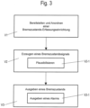
- Figure 3 shows a schematic flow diagram of a further method according to the invention for detecting a braking state of a service brake cylinder 1 according to Figure 1 .
- the brake state signals generated by the sensor 11 are checked for plausibility by at least one further sensor 11.
- the output brake states A, L are further checked with signals for applying and/or releasing the service brake cylinder 1 of a higher-level brake control, and an alarm is issued if no application state A is detected after receiving a signal for applying the service brake cylinder 1, or/and if no release state L is detected after receiving a signal for releasing the service brake cylinder 1.
- the senor 11 and/or the redundant sensor(s) 11 are based on an optical distance measuring principle, such as a reflection light barrier, laser, on an acoustic distance measuring principle, such as ultrasound, or on an electromagnetic distance measuring principle, such as radar.
- an optical distance measuring principle such as a reflection light barrier, laser
- an acoustic distance measuring principle such as ultrasound
- an electromagnetic distance measuring principle such as radar.
- connections 18, 18', 20, 23, 23a can also be optical conductors and/or wireless transmission links, depending on the application.
Landscapes
- Engineering & Computer Science (AREA)
- General Engineering & Computer Science (AREA)
- Mechanical Engineering (AREA)
- Braking Arrangements (AREA)
- Valves And Accessory Devices For Braking Systems (AREA)
Description
- Die Erfindung betrifft einen Betriebsbremszylinder, insbesondere einer Klotzbremse, mit Bremszustandserfassung, insbesondere für ein Schienenfahrzeug, nach dem Oberbegriff des Anspruchs 1. Die Erfindung bezieht sich auch auf ein Verfahren zum Erfassen eines Bremszustands eines Betriebsbremszylinders, insbesondere einer Klotzbremse.
- Eine Klotzbremse, die auch Laufflächenbremse genannt wird, wird bei Schienenfahrzeugen als Reibungsbremse in Güterfahrzeugen sehr häufig eingesetzt, da sie einfach aufgebaut ist und die Bremsklötze mit ihrem Reibbelag die Radlauffläche des abzubremsenden Rades als Reibfläche benutzen.
- Bei einer solchen Laufflächenbremse verschleißen Bremsklötze und Räder während des täglichen Betriebs. Der Zustand der Bremse, d.h. der Bremsklötze, muss aus Sicherheitsgründen regelmäßig überprüft werden. Das aktuelle Kontrollverfahren ist die regelmäßige Sichtkontrolle und Prüfen mit einem Werkzeug, z.B. Hammer, im angelegten und gelösten Zustand der Bremsklötze durch das Wartungspersonal. Das ist kostenintensiv und erfordert gut ausgebildetes Wartungspersonal.
- Für eine Überprüfung der Bremse, ob diese auch während der Fahrt des Zuges nach einem Lösen tatsächlich gelöst ist und sich nach einem Anlegen auch in einem Anlagezustand befindet, sind unterschiedliche Lösungsvorschläge gemacht worden.
- Das Dokument
WO 2015/135074 A1 beschreibt eine Bremseinstellungs-Überwachungsvorrichtung für ein Druckluftbremssystem, welche einen berührungslosen Näherungssensor umfasst, der an einer Wand einer Bremskammer montiert ist, um ein Signal zu erzeugen, wenn die Rückplatte der Schubstange in den Erfassungsabstand des Näherungssensors kommt. Als nachteilig wird es dabei gesehen, dass der Näherungssensor durch eine in das Gehäuse der Bremskammer eingebrachte Öffnung mit einem Teil in die Bremskammer hervorsteht und mit einem anderen Teil, das einen elektrischen Anschluss mit Kabei aufweist, nach außen in die Umgebung hervorsteht und den Umgebungsbedingungen ausgesetzt ist. - Ähnliche Ausführungen sind in den folgenden Dokumenten beschrieben:
DE102015219058A ;DE19857092B4 ;EP1384638B1 ;EP1640233B1 ;US4583071A ;US5816778A ;US6352137B1 ;US6501375B1 ;US7624849B2 ;US8616342B2 ;US8662602B2 WO2015135074A1 ;WO2016040430A1 . - Daher besteht die Aufgabe der Erfindung darin, einen gattungsgemäßen Betriebsbremszylinder, insbesondere einer Klotzbremse, mit einer verbesserten Bremszustandserfassung bei gleichzeitiger Reduzierung von Kosten und Bauteilen zu schaffen.
- Die Aufgabe wird durch einen Betriebsbremszylinder mit den Merkmalen des Anspruchs 1 und ein Verfahren mit den Merkmalen des Anspruchs 6 gelöst.
- Ein erfindungsgemäßer Betriebsbremszylinder, insbesondere einer Klotzbremse, umfasst ein Gehäuse mit einer Spindel und einer Bremszustands-Erfassungseinrichtung zur Erfassung eines Anlegezustands und eines Lösezustands des Betriebsbremszylinders. Die Bremszustands-Erfassungseinrichtung ist vollständig innerhalb eines Innenraums des Betriebsbremszylinders von dem Gehäuse umschlossen angeordnet und erfasst die Position der Spindel. Die Bremszustands-Erfassungseinrichtung liefert eine Information über die Kolbenposition. Eine solche Bremszustands-Erfassungseinrichtung ist vorteilhaft, nicht nur weil sie das Sicherheitsniveau gegenüber der derzeit etablierten manuellen Überprüfung erhöht, sondern auch einen einfachen Aufbau bietet.
- Ein besonderer Vorteil ist es, dass die Bremszustands-Erfassungseinrichtung in dem Innenraum in dem Gehäuse des Betriebsbremszylinders vollständig von dem Gehäuse umgeben vor Witterungseinflüssen und Beschädigungen gut geschützt ist. Die Bremszustands-Erfassungseinrichtung ist im Wartungsfall von außen erreichbar, z.B. durch eine wieder verschließbare Wartungsöffnung. Ein erfindungsgemäßes Verfahren zum Erfassen eines Bremszustands des oben angegebenen Betriebsbremszylinders umfasst die Verfahrensschritte (V1) Bereitstellen einer Bremszustands-Erfassungseinrichtung und Anordnen der Bremszustands-Erfassungseinrichtung innerhalb des Betriebsbremszylinders und Versorgen mindestens eines Sensors der Bremszustands-Erfassungseinrichtung mit elektrischer Energie; (V2) Erzeugen mindestens eines elektrischen Signals als Bremszustandssignal in Abhängigkeit von einem Bremszustand, nämlich Anlegezustand und/oder Lösezustand, durch den Sensor; und (V3) Ausgeben eines erfassten Bremszustands als Anlegezustand oder Lösezustand des Betriebsbremszylinders anhand der so erfassten Bremszustandssignale.
- Es ist von Vorteil, dass die erfassten Zustände, also Anlegezustand und Lösezustand in einfacher Weise mittels der Bremszustands-Erfassungseinrichtung objektive und für eine automatische Verarbeitung geeignete Daten liefern. Zusätzlich kann der Bediener die Daten zur Überwachung des Löse- oder Bremsbetätigungszustandes der Bremse verwenden.
- Ein besonderer Vorteil besteht darin, dass diese erfassten Daten in Tunneln (z.B.: U-Bahnen oder langen Zugtunneln) oder im automatischen/autonomen Betrieb unerlässlich sind, um eine fehlerhafte Bremsbetätigung zu vermeiden, die in einem nicht gut belüfteten Bereich zu unerwartetem Rauch führen kann. Zudem können somit mögliche Brandherde früh genug erkannt und verhindert werden.
- Vorteilhafte Weiterbildungen der Erfindung sind durch die Gegenstände der Unteransprüche angegeben.
- Gemäß der Erfindung, erfasst die Bremszustands-Erfassungseinrichtung die Position eines Druckrings oder eines Spindelgehäuses, welche mit der Spindel verbunden sind. So können vorteilhaft bereits vorhandene Funktionsbauteile oder deren Abschnitte direkt oder indirekt zur Erfassung der Position der Spindel und somit des Zustands des Betriebsbremszylinders verwendet werden.
- Gemäß der Erfindung, weist die Bremszustands-Erfassungseinrichtung mindestens einen Sensor auf, der in einem Innenraumabschnitt des Gehäuses des Betriebsbremszylinders zwischen einer Frontwand und einem Vorsprung des Spindelgehäuses angeordnet ist. In diesem Bereich sind vorteilhaft keine anderen störenden Bauteile wie z.B. ihre Lage oder/und Form verändernde Federn vorhanden, die beim Erfassen einer Position der Spindel zu Fehlern führen könnten.
- In einer weiteren Ausführung ist der mindestens eine Sensor mittels eines Befestigungsabschnitts an einer Halterung befestigt, wobei eine axiale Position des mindestens einen Sensors an der Halterung einstellbar ist. Dies ist von Vorteil, da einerseits mittels der Halterung eine einfache Anordnung und Befestigung gewährleistet wird, und andererseits damit eine Position des Sensors in Zusammenwirkung mit dem Teil, dessen Position zu erfassen ist, einfach zu justieren ist.
- Die Halterung kann auch so ausgebildet sein, dass sie mehr als einen Sensor aufnehmen kann. Dies ist vorteilhaft, wenn ein weiterer Sensor zu Plausibilisierung verwendet wird.
- In einer noch weiteren Ausführung wirkt der mindestens eine Sensor mit dem Vorsprung des Spindelgehäuses derart zusammen, dass der mindestens eine Sensor in Abhängigkeit von der Position des Vorsprungs des Spindelgehäuses im Anlegezustand (A) des Betriebsbremszylinders aktiviert ist und im Lösezustand (L) des Betriebsbremszylinders nicht aktiviert ist. Dies ergibt einen einfachen Aufbau mit geringer Teilezahl.
- Eine Ausführung sieht vor, dass der mindestens eine Sensor als ein induktiver Näherungssensor oder Näherungsschalter ausgebildet ist. Derartige Bauteile sind kostengünstig in hoher Qualität am Markt in passender Ausführung verfügbar.
- Alternativ oder als zusätzlicher Sensor kann der mindestens eine Sensor ein kontaktbehafteter oder/und kontaktloser Sensor sein.
- Bei dem erfindungsgemäßen Verfahren wird in dem Verfahrensschritt (V2) das von dem mindestens einen Sensor erzeugte mindestens eine Bremszustandssignal anhand mindestens eines weiteren von mindestens einem weiteren Sensor erzeugten Bremszustandssignals plausibilisiert. Dieser weitere Sensor kann z.B. an der gleichen Halterung angebracht sein. Es ist aber auch möglich, dass der weitere Sensor auch im Gehäuse des Betriebsbremszylinders an einer anderen Stelle angeordnet ist und den Lösezustand erfasst, wobei der erste Sensor den Anlegezustand erfasst.
- Eine noch weitere Ausführung des erfindungsgemäßen Verfahrens sieht vor, dass als Anlegezustand (A) oder Lösezustand (L) des Betriebsbremszylinders im Verfahrensschritt (V3) ausgegebenen Bremszustände (A, L) mit Signalen zum Anlegen und/oder Lösen des Betriebsbremszylinders einer übergeordneten Bremssteuerung überprüft werden, und ein Alarm ausgegeben wird, wenn nach Erhalt eines Signals zum Anlegen des Betriebsbremszylinders kein Anlegezustand (A) erfasst wird, oder/und wenn nach Erhalt eines Signals zum Lösen des Betriebsbremszylinders kein Lösezustand (L) erfasst wird. Dies ist von Vorteil, da auf diese Weise eine einfache und wirkungsvolle Erfassung von nicht gelösten Bremsklötzen im Lösezustand und von nicht angelegten Bremsklötzen im Anlegezustand ermöglicht werden kann.
- Ein Ausführungsbeispiel der Erfindung wird nachfolgend anhand der beigefügten Zeichnungen beschrieben.
- Es zeigen:
- Figur 1
- eine schematische Schnittdarstellung Ausführungsbeispiel eines erfindungsgemäßen Betriebsbremszylinders mit einer Bremszustand-Erfassungseinrichtung; und
- Figur 2-3
- schematische Flussdiagramme erfindungsgemäßer Verfahren zum Erfassen eines Bremszustands eines Betriebsbremszylinders nach
Figur 1 . -
Figur 1 zeigt eine schematische Schnittdarstellung eines erfindungsgemäßen Betriebsbremszylinders 1 mit einer Bremszustand-Erfassungseinrichtung 10. - Der Betriebsbremszylinder 1 ist in diesem Beispiel als Betriebsbremszylinder 1 einer so genannten Klotzbremse ausgebildet, die auch als Laufflächenbremse bezeichnet wird. In einer anderen Ausführung ist die Bremsvorrichtung 1 eine Scheibenbremse, was hier nicht dargestellt aber vorstellbar ist.
- Der Betriebsbremszylinder 1 umfasst ein Gehäuse 2, eine Spindel 5, einen Druckring 7 und ein Spindelgehäuse 8. Der allgemein bekannte Aufbau, die Funktion des Betriebsbremszylinders 4 und das Zusammenwirken mit Bremsgestänge, Bremszangen oder/und Bremsklötzen werden hier nicht weiter im Detail beschrieben.
- Das Gehäuse 2 des Betriebsbremszylinders 1 weist eine Rückwand 2a und eine dieser gegenüberliegende Frontwand 2b auf. Eine umlaufende Gehäusewand 2c verbindet die geschlossene Rückwand 2a und die Frontwand 2b. Ein Innenraum 3 des Gehäuses 2 ist durch die Rückwand 2a, die Frontwand 2b und die Gehäusewand 2c festgelegt.
- In dem Innenraum 3 des Gehäuses 2 des Betriebsbremszylinders 1 ist die Spindel 5 zwischen der Rückwand 2a und der Frontwand 2b in einer Bewegungsrichtung x, welche in Spindel 5 verläuft, verschiebbar angeordnet. Die Spindel 5 ist mit einem nicht bezeichneten Betriebsbremskolben verbunden, wobei ein Bremsklotzschuh 6 an einem durch die Frontwand 2b hervorstehenden Ende der Spindel 5 angebracht ist. Der Bremsklotzschuh 6 ist mit einem nicht gezeigten Bremsbelag/Bremsklotz verbunden. Der Bremsbelag steht mit einem ebenfalls nicht gezeigten, aber leicht vorzustellenden, abzubremsenden Rad bei Bremsvorgängen in Zusammenwirkung.
- In einem mittleren Abschnitt der Spindel 5 sind hier der Druckring 7 und das Spindelgehäuse 8 um die Spindel 5 herum angeordnet und mit ihr in nicht näher beschriebener Weise gekoppelt. Das Spindelgehäuse 8 weist einen radialen Vorsprung 9 in Form eines Flanschabschnitts auf. Dieser Vorsprung 9 legt einen Abschnitt des Innenraums 3 zwischen sich, der Frontwand 2b, Gehäusewand 2c und eine Außenseite des Spindelgehäuses 8 fest.
- Die Bremse, d.h. der Betriebsbremszylinder 1, hat zwei Grundzustände, nämlich den Anlegezustand A und den Lösezustand L.
- In dem Lösezustand L, welcher in
Fig. 1 dargestellt ist, wird ein bestimmter Abstand zwischen dem abzubremsenden Rad und dem Bremsklotz/Bremsbelag durch die Stellung der Spindel 5 eingehalten. Dabei ist die Spindel 5 in das Gehäuse 2 eingefahren. - Wenn die Bremse angelegt bzw. zugespannt wird, bewegt sich die Spindel 5 in dem Betriebsbremszylinder 1 zusammen mit dem Druckring 7 und dem Spindelgehäuse 8 in Richtung der Spindel 5 in positiver Bewegungsrichtung x, und somit wird auch der Bremsklotz/Bremsbelag auf das abzubremsende Rad für einen Bremsvorgang gepresst. Dabei wird ein Abstand zwischen dem Vorsprung 9 des Spindelgehäuses 8 und der Rückwand 2a des Gehäuses 2 des Betriebsbremszylinders 2 vergrößert. Gleichzeitig wird ein Abstand zwischen dem Vorsprung 9 des Spindelgehäuses 8 und der Frontwand 2a des Gehäuses 2 verkleinert. Am Ende dieser Anlege- bzw. Zuspannbewegung nimmt die Bremse bzw. der Betriebsbremszylinder 1 den Anlegezustand A ein. Dabei ist die Spindel 5 mit ihrem mit dem Bremsklotzschuh 6 verbundenen Ende aus dem Gehäuse 2 um ein bestimmtes Maß herausgefahren.
- Beim Lösen der Bremse verläuft die Bewegung umgekehrt in negativer Bewegungsrichtung x. Dabei nähert sich das Spindelgehäuse 8 der Rückwand 2a des Gehäuses 2. Die Bremse bzw. der Betriebsbremszylinder 1 befindet sich nach dem Lösen in dem Lösezustand L.
- Diese beiden Zustände der Bremse bzw. des Betriebsbremszylinders 1, nämlich der Lösezustand L und der Anlegezustand A, können mit der Bremszustands-Erfassungseinrichtung 10 erfasst werden.
- Die Anordnung der Bremszustands-Erfassungseinrichtung 10 ist so gewählt, dass die Bremszustands-Erfassungseinrichtung 10 mit einem in Richtung der Spindel 5 bewegbaren Bauteil zusammenwirken kann, um entweder den Lösezustand L, den Anlegezustand A oder beide Zustände zu erfassen.
- In dem gezeigten Ausführungsbeispiel ist ein geeignetes Bauteil zur Überwachung der beiden Zustände (Lösezustand L und Anlegezustand A) der Druckring 7 oder/und das Spindelgehäuse 8, da diese Bauteile mit der Bewegung der Spindel 5 beim Anlegen und Lösen der Bremse mitbewegt werden.
- Die Bremszustands-Erfassungseinrichtung 10 umfasst hier einen Sensor 11 innerhalb des Gehäuses 2 des Betriebsbremszylinders 2 in dem Innenraum 3.
- Die Bremszustands-Erfassungseinrichtung 10 ist hier in dem Innenraum 3 des Gehäuses 2 innerhalb des Gehäuses 2 des Betriebsbremszylinders 1 angeordnet. Der Sensor 11 ist hier zwischen der Frontwand 2b und dem Vorsprung 9 des Spindelgehäuses 8 in dem Innenraum 3 an einer Halterung 15 befestigt.
- Alternativ kann der Sensor 11 oder auch ein zusätzlicher Sensor 11 in einem anderen Abschnitt in dem Innenraum 3 innerhalb des Gehäuses 2 zwischen der Rückwand 2a und dem Vorsprung 9 des Spindelgehäuses 8 angeordnet sein.
- In diesem Ausführungsbeispiel ist der Sensor 11 als ein induktiver Näherungssensor oder induktiver Näherungsschalter ausgebildet, welcher mit dem metallischen Vorsprung 9 des Spindelgehäuses 8 derart zusammenwirkt, dass der Sensor 11 in Abhängigkeit von der Position des Vorsprungs 9 des Spindelgehäuses 8 im Anlegezustand A aktiviert ist und im Lösezustand L nicht aktiviert ist.
- Der Sensor weist eine Erfassungsseite 12, einen Anschlussabschnitt 13 und einen Befestigungsabschnitt 14 auf. Im eingebauten Zustand weist die Erfassungsseite 12 zu dem Vorsprung 9 des Spindelgehäuses 8. Der Anschlussabschnitt 13 dient zum elektrischen Anschluss des Sensors 11 und weist eine entsprechende IP-Schutzart gegen Eindringen von Feuchtigkeit und Schmutz mit z.B. einem schon dicht eingeführten/eingespritzten Kabel auf.
- Wenn die Bremse angelegt bzw. zugespannt wird, bewegt sich das Spindelgehäuse 8 mit dem Vorsprung 9 in positiver Bewegungsrichtung +X auf die Erfassungsseite 12 des Sensors 11 zu. Wenn der Anlegezustand A eingenommen wird, wird ein sensorspezifischer Abstandswert des Vorsprungs 9 (in Richtung der Spindel 5) zu der Erfassungsseite 12 des Sensors 11 unterschritten und der Sensor 11 aktiviert. Dieser sensorspezifische Abstandswert bzw. Aktivbereich des Sensors 11 kann vorher festgelegt werden, z.B. am Sensor 11 oder/und mittels eines Steuergerätes 17.
- Beim Lösen der Bremse wird der Sensor 11 deaktiviert, sobald der sensorspezifische Abstandswert zwischen Vorsprung 9 und Erfassungsseite 12 des Sensors 11 überschritten wird, d.h. wenn der Vorsprung 9 den Aktivbereich des Sensors 11 verlässt.
- Der Befestigungsabschnitt 14 des Sensors 11 ermöglicht eine Positionsanpassung des Sensors 11 in einem bestimmten Bereich in der Halterung 15, z.B. in einem axialen Bereich parallel zu Spindel 5. Damit kann der Aktivbereich des Sensors 11 an die Position des Vorsprungs 9 angepasst werden.
- Auf diese Weise ist es möglich, den Anlegezustand A durch den aktivierten Sensor 11 genau zu erfassen. Wenn der Sensor 11 dann deaktiviert wird und deaktiviert ist, kann der Lösezustand L eingenommen sein. Der Lösezustand L kann dabei jedoch nur angenommen werden, da keine Plausibilisierung vorhanden ist.
- Eine solche Plausibilisierung des Lösezustands L kann beispielsweise durch Erfassung der Position des Vorsprungs 9 in dem Lösezustand L durch einen weiteren Sensor 11 erfolgen. Dieser weitere Sensor 11 erfasst dann den Lösezustand L, indem der weitere Sensor 11 aktiviert ist.
- In einer solchen Ausführung, die nicht gezeigt aber leicht vorstellbar ist, sind zwei Sensoren 11 so in dem Innenraum 3 des Gehäuses 2 angeordnet, dass der eine von den zwei Sensoren 11 den Lösezustand L und der andere von den zwei Sensoren 11 den Anlegezustand A erfasst.
- Der Sensor 11 ist mit einer elektrisch leitenden Anschlussleitung 16 mit einem Steuergerät 17 verbunden. Das Steuergerät 17 versorgt den Sensor 11 über die Anschlussleitung 16 mit elektrischer Energie und empfängt Signale des Sensors 11 als Bremszustandssignale. Die Signale des Sensors 11 entsprechen dem jeweiligen Bremszustand des Betriebsbremszylinders 1, nämlich dem Lösezustand L und dem Anlegezustand A, und können von dem Steuergerät 17 weiterbearbeitet, wie z.B. verstärkt, geformt usw., werden. Diese Bremszustandssignale sind im einfachsten Fall als digitale Schaltsignale ("EIN", "AUS"), d.h. der eine Zustand wird durch das Vorhandensein einer Amplitude eines Signals, z.B. eines Spannungs- oder Stromwertes dargestellt, und der andere Zustand durch das Nichtvorhandensein einer Amplitude eines Signals, z.B. eines Spannungs- oder Stromwertes. Zwischenwerte sind nicht erforderlich. Natürlich können die beiden Zustände auch durch unterschiedliche elektrische Spannungen oder/und Ströme, Widerstände, Frequenzen o.dgl. dargestellt werden.
- Dann erfolgt eine Weiterleitung über eine Verbindung 18 über ein weiteres Steuergerät 19 mittels einer weiteren elektrisch leitenden Verbindung 20 an eine Auswerteeinheit 21.
- Die Auswerteeinheit 21 gibt an einem Ausgang 22 z.B. ein Ausgangsignal als Anzeige des Bremszustands A, L optisch, akustisch, haptisch aus. Beispielsweise kann eine Bildschirmanzeige eines gesamten Bremssystems eines Zuges erfolgen, wobei der Bremszustand eines jeden Betriebsbremszylinders 1 übersichtlich dargestellt wird. Das Ausgangssignal kann auch gespeichert oder anderweitig weiterverarbeitet werden.
- Die Auswerteeinheit 21 ist zudem über eine Verbindung 23 mit einer übergeordneten Bremssteuerung (nicht gezeigt) verbunden, von der die Auswerteeinheit 21 Bremsanlege- und -lösesignale erhält, um diese mit den jeweiligen erfassten Bremszuständen der Betriebsbremszylinder 1 zu vergleichen. Natürlich können auch andere Daten ausgetauscht werden.
- in der
Figur 1 ist ein weiteres Steuergerät 17' mit einer Anschlussleitung 16' für einen weiteren Sensor 11 (nicht gezeigt) und einer Verbindung 18' angegeben. Dieser weitere Sensor 11 kann z.B. als zweiter, redundanter Sensor 11 in dem Betriebsbremszylinder 1 angeordnet sein. Es können auch mehr zwei solche Sensoren 11 vorgesehen sein. - Zudem soll das weitere Steuergerät 17' stellvertretend für eine Anzahl von Steuergeräten 17 stehen, die für ein komplettes Bremssystem eines Zuges, dem die Betriebsbremszylinder 1 zugeordnet sind, mit einer Anzahl von Betriebsbremszylindern 1 mit jeweiliger Bremszustands-Erfassungseinrichtung 10 mit entsprechenden Bremszustandssignalen erforderlich sind. Diese Anzahl von Bremszustandssignalen des gesamten Bremssystems wird in dem weiteren Steuergerät 19, z.B. auch im Zusammenhang mit Daten aus der übergeordneten Bremssteuerung über eine weitere Verbindung 23a, für eine einfache und schnelle Auswertung in der Auswerteeinheit 21 vorbereitet.
- Der Sensor 11 kann ein kontaktbehafteter oder/und kontaktloser Sensor 11 sein.
- Der Sensor 11 ist in dem Innenraum 3 in dem Gehäuse 2 des Betriebsbremszylinders 1 vor Witterungseinflüssen und Beschädigungen gut geschützt. Der Sensor 11 ist im Wartungsfall von außen erreichbar, z.B. durch eine wieder verschließbare Wartungsöffnung.
- Form und Werkstoffe des Sensors 11 sind so bemessen, dass die Effizienz des Sensors 11 maximiert werden kann. Dazu sind bestimmte Kunststoffe als Gehäuse verwendbar, welche gegenüber den im Betriebsbremszylinder 1 vorkommenden Medien, wie z.B. Schmierstoff, resistent sind. Außerdem können geeignete metallische Abschirmungen des Sensors 11 dessen elektromagnetische Verträglichkeit gegenüber Einstrahlung von Störsignalen verbessern.
-
Figur 2 ein schematisches Flussdiagramm eines erfindungsgemäßen Verfahrens zum Erfassen eines Bremszustands eines Betriebsbremszylinders 1 nachFigur 1 dar. - In einem ersten Verfahrensschritt V1 wird eine Bremszustands-Erfassungseinrichtung 10 in einem Betriebsbremszylinder 1 bereitgestellt. Ein Sensor 11 der Bremszustands-Erfassungseinrichtung 10 wird mit elektrischer Energie versorgt.
- Dann werden in einem zweiten Verfahrensschritt V2 elektrische Signale des Sensors 11 als Bremszustandssignale in Abhängigkeit von einem Bremszustand, nämlich Anlegezustand A und Lösezustand L, von dem Sensor 11 erzeugt.
- In einem dritten Verfahrensschritt V3 werden die so erhaltenen Bremszustandssignale als erfasster Bremszustand Anlegezustand A oder Lösezustand L ausgegeben.
-
Figur 3 zeigt ein schematisches Flussdiagramm eines weiteren erfindungsgemäßen Verfahrens zum Erfassen eines Bremszustands eines Betriebsbremszylinders 1 nachFigur 1 . - Die Verfahrensschritte V1, V2 und V3 entsprechen denjenigen des Verfahrens nach
Figur 2 . - Zusätzlich werden hier in einem untergeordneten Verfahrensschritt V2-1 des zweiten Verfahrensschritts V2 die von dem Sensor 11 erzeugten Bremszustandssignale von mindestens einem weiteren Sensor 11 plausibilisiert.
- In einem zusätzlichen untergeordneten Verfahrensschritt V3-1 des dritten Verfahrensschritts V3 werden die ausgegebenen Bremszustände A, L weiterhin mit Signalen zum Anlegen und/oder Lösen des Betriebsbremszylinders 1 einer übergeordneten Bremssteuerung überprüft, und ein Alarm ausgegeben, wenn nach Erhalt eines Signals zum Anlegen des Betriebsbremszylinders 1 kein Anlegezustand A erfasst wird, oder/und wenn nach Erhalt eines Signals zum Lösen des Betriebsbremszylinders 1 kein Lösezustand L erfasst wird.
- Die Erfindung ist durch das oben angegebene Ausführungsbeispiel nicht eingeschränkt, sondern im Rahmen der Ansprüche modifizierbar.
- So ist es z.B. denkbar, dass der Sensor 11 oder/und der/die redundante/n Sensorten 11 auf einem optischen Entfernungsmessprinzip, wie z.B. Reflexionslichtschranke, Laser, auf einem akustischen Entfernungsmessprinzip, wie z.B. Ultraschall, oder auf einem elektromagnetischem Entfernungsmessprinzip, wie z.B. Radar, beruht.
- Die Verbindungen 18, 18', 20, 23, 23a können auch je nach Einsatzfall optische Leiter oder/und drahtlose Übertragungsstrecken sein.
-
- 1
- Betriebsbremszylinder
- 2
- Gehäuse
- 2a
- Rückwand
- 2b
- Frontwand
- 3
- Innenraum
- 4
- - entfällt -
- 5
- Spindel
- 6
- Bremsklotzschuh
- 7
- Druckring
- 8
- Spindelgehäuse
- 9
- Vorsprung
- 10
- Bremszustands-Erfassungseinrichtung
- 11
- Sensor
- 12
- Erfassungsseite
- 13
- Anschlussabschnitt
- 14
- Befestigungsabschnitt
- 15
- Halterung
- 16, 16'
- Anschlussleitung
- 17, 17'; 19
- Steuergerät
- 18, 18'; 20
- Verbindung
- 21
- Auswerteeinheit
- 22
- Ausgang
- 23, 23a
- Verbindung
- A
- Anlegeposition/Anlegezustand
- L
- Löseposition/Lösezustand
- V1 ...3; 2-1; 3-1
- Verfahrensschritt
- x
- Bewegungsrichtung
Claims (7)
- Betriebsbremszylinder (1), insbesondere einer Klotzbremse, aufweisend ein Gehäuse (2) mit einer Spindel (5) und einer Bremszustands-Erfassungseinrichtung (10) zur Erfassung eines Anlegezustands (A) und eines Lösezustands (L) des Betriebsbremszylinders (1) angeordnet ist, wobei die Bremszustands-Erfassungseinrichtung (10) vollständig innerhalb eines Innenraums (3) des Betriebsbremszylinders (1) von dem Gehäuse (2) umschlossen angeordnet ist und die Position der Spindel (5) erfasst, wobei die Bremszustands-Erfassungseinrichtung (10) die Position eines Druckrings (7) oder eines Spindelgehäuses (8), welche mit der Spindel (5) verbunden sind, erfasst, wobei die Bremszustands-Erfassungseinrichtung (10) mindestens einen Sensor (11) aufweist, der in einem Innenraum (3) des Gehäuses (2) des Betriebsbremszylinders (2) zwischen einer Frontwand (2b) und einem Vorsprung (9) des Spindelgehäuses (8) angeordnet ist,
dadurch gekennzeichnet, dass ein weiterer Sensor (11) in dem Innenraum (3) des Gehäuses (2) angeordnet ist, welcher mindestens ein Bremszustandssignals des mindestens einen Sensors (11) anhand mindestens eines weiteren von dem mindestens einem weiteren Sensor (11) erzeugten Bremszustandssignals plausibilisiert. - Betriebsbremszylinder (1) nach Anspruch 1, dadurch gekennzeichnet, dass der mindestens eine Sensor (11) mittels eines Befestigungsabschnitts (14) an einer Halterung (15) befestigt ist, wobei eine axiale Position des mindestens einen Sensors (11) an der Halterung (15) einstellbar ist.
- Betriebsbremszylinder (1) nach Anspruch 1 oder 2, dadurch gekennzeichnet, dass der mindestens eine Sensor (11) mit dem Vorsprung (9) des Spindelgehäuses (8) derart zusammenwirkt, dass der mindestens eine Sensor (11) in Abhängigkeit von der Position des Vorsprungs (9) des Spindelgehäuses (8) im Anlegezustand (A) des Betriebsbremszylinders (1) aktiviert ist und im Lösezustand (L) des Betriebsbremszylinders (1) nicht aktiviert ist.
- Betriebsbremszylinder (1), nach einem der Ansprüche 1 bis 3, dadurch gekennzeichnet, dass der mindestens eine Sensor (11) als ein induktiver Näherungssensor oder Näherungsschalter ausgebildet ist.
- Betriebsbremszylinder (1) nach einem der Ansprüche 1 bis 4, dadurch gekennzeichnet, dass der mindestens eine Sensor (11) ein kontaktbehafteter oder/und kontaktloser Sensor (11) ist.
- Verfahren zum Erfassen eines Bremszustands eines Betriebsbremszylinders (1) nach einem der vorhergehenden Ansprüche, mit den Verfahrensschritten(V1) Bereitstellen einer Bremszustands-Erfassungseinrichtung (10) und Anordnen der Bremszustands-Erfassungseinrichtung (10) innerhalb des Betriebsbremszylinders (1) und Versorgen mindestens eines Sensors (11) der Bremszustands-Erfassungseinrichtung (10) mit elektrischer Energie;(V2) Erzeugen mindestens eines elektrischen Signals als Bremszustands-signal in Abhängigkeit von einem Bremszustand, nämlich Anlegezustand (A) und/oder Lösezustand (L), durch den Sensor (11); und(V3) Ausgeben eines erfassten Bremszustands als Anlegezustand (A) oder Lösezustand (L) des Betriebsbremszylinders (1) anhand der so erfassten Bremszustandssignale,dadurch gekennzeichnet, dass in dem Verfahrensschritt (V2) das von dem mindestens einen Sensor (11) erzeugte mindestens eine Bremszustandssignal anhand mindestens eines weiteren von mindestens einem weiteren Sensor (11) erzeugten Bremszustandssignals in einem untergeordneten Verfahrensschritt (V2-1) plausibilisiert wird.
- Verfahren nach Anspruch 6, dadurch gekennzeichnet, dass die als Anlegezustand (A) oder Lösezustand (L) des Betriebsbremszylinders (1) im Verfahrensschritt (V3) ausgegebenen Bremszustände (A, L) in einem untergeordneten Verfahrensschritt (V3-1) mit Signalen zum Anlegen und/oder Lösen des Betriebsbremszylinders (1) einer übergeordneten Bremssteuerung überprüft werden, und ein Alarm ausgegeben wird, wenn nach Erhalt eines Signals zum Anlegen des Betriebsbremszylinders (1) kein Anlegezustand (A) erfasst wird, oder/und wenn nach Erhalt eines Signals zum Lösen des Betriebsbremszylinders (1) kein Lösezustand (L) erfasst wird.
Applications Claiming Priority (2)
| Application Number | Priority Date | Filing Date | Title |
|---|---|---|---|
| DE102020107835.8A DE102020107835A1 (de) | 2020-03-23 | 2020-03-23 | Betriebsbremszylinder, insbesondere einer Klotzbremse, mit Bremszustandserfassung und Verfahren zum Erfassen eines Bremszustands eines Betriebsbremszylinders, insbesondere einer Klotzbremse |
| PCT/EP2021/055058 WO2021190866A1 (de) | 2020-03-23 | 2021-03-01 | Betriebsbremszylinder mit bremszustandserfassung und verfahren zum erfassen eines bremszustands eines betriebsbremszylinders |
Publications (2)
| Publication Number | Publication Date |
|---|---|
| EP4126630A1 EP4126630A1 (de) | 2023-02-08 |
| EP4126630B1 true EP4126630B1 (de) | 2024-12-25 |
Family
ID=74853648
Family Applications (1)
| Application Number | Title | Priority Date | Filing Date |
|---|---|---|---|
| EP21709390.5A Active EP4126630B1 (de) | 2020-03-23 | 2021-03-01 | Betriebsbremszylinder mit bremszustandserfassung und verfahren zum erfassen eines bremszustands eines betriebsbremszylinders |
Country Status (3)
| Country | Link |
|---|---|
| EP (1) | EP4126630B1 (de) |
| DE (1) | DE102020107835A1 (de) |
| WO (1) | WO2021190866A1 (de) |
Families Citing this family (1)
| Publication number | Priority date | Publication date | Assignee | Title |
|---|---|---|---|---|
| US12358770B2 (en) | 2022-07-01 | 2025-07-15 | Darron Alderman | Man basket for attachment to telehandler |
Family Cites Families (16)
| Publication number | Priority date | Publication date | Assignee | Title |
|---|---|---|---|---|
| US4583071A (en) | 1984-05-02 | 1986-04-15 | Adam Sebalos | Brake adjustment monitoring device for automotive vehicles |
| US5816778A (en) | 1996-01-16 | 1998-10-06 | Micron Technology, Inc. | System for controlling the stroke length of a double-diaphragm pump |
| WO1998016407A1 (en) | 1996-10-11 | 1998-04-23 | Indian Head Industries, Inc. | Brake monitoring system |
| DE19857092B4 (de) | 1998-12-10 | 2006-03-02 | Knorr-Bremse Systeme für Schienenfahrzeuge GmbH | Bremsbacke, insbesondere für Scheibenbremseinrichtungen für den Einsatz in Schienenfahrzeugen |
| US6352137B1 (en) | 2000-03-22 | 2002-03-05 | Indian Head Industries, Inc. | Brake monitoring system |
| CA2456242C (en) | 2001-08-03 | 2011-03-15 | Spectra Products Inc. | Brake system |
| DE10233844B4 (de) | 2002-07-25 | 2007-06-14 | Knorr-Bremse Systeme für Schienenfahrzeuge GmbH | Vorrichtung und Verfahren zur Überwachung des Funktions- und/oder Verschleißzustandes von Bremsbelägen und Bremsscheiben einer Fahrzeugbremse |
| DE102004045846A1 (de) | 2004-09-20 | 2006-03-23 | Faiveley Transport Remscheid Gmbh | Vorrichtung und Verfahren zur Überwachung der Funktion einer Bremszange |
| JP5014916B2 (ja) | 2007-08-10 | 2012-08-29 | 日立オートモティブシステムズ株式会社 | ブレーキ制御装置 |
| DE102010011725A1 (de) | 2010-03-17 | 2011-09-22 | Haldex Brake Products Ab | Scheibenbremse und Herstellungsverfahren für eine Scheibenbremse |
| KR101681799B1 (ko) | 2010-06-18 | 2016-12-12 | 인디언 헤드 인더스트리즈, 인코포레이티드 | 에어 디스크 브레이크용 전자 스트로크 센서 |
| DE102011100726A1 (de) * | 2011-05-06 | 2012-11-08 | Man Truck & Bus Ag | Verfahren und Vorrichtung zum Überwachen des Bremsbelagverschleißes und Lüftspiels einer Betriebsbremse in Kraftfahrzeugen |
| WO2015135074A1 (en) | 2014-03-12 | 2015-09-17 | Schmidt Dieter Albert | Brake chamber with proximity sensor |
| US9616875B2 (en) | 2014-09-11 | 2017-04-11 | Westinghouse Air Brake Technologies Corporation | Piston stroke sensor arrangement for a brake unit |
| DE102015219058B3 (de) * | 2015-09-29 | 2017-04-13 | Kes Keschwari Electronic Systems Gmbh & Co. Kg | Bremszylinder mit integriertem Verschleißnachsteller für Schienenfahrzeuge |
| DE102015013199A1 (de) | 2015-10-12 | 2017-04-13 | Wabco Europe Bvba | Überwachungseinrichtung für eine Scheibenbremse eines Kraftfahrzeuges |
-
2020
- 2020-03-23 DE DE102020107835.8A patent/DE102020107835A1/de not_active Ceased
-
2021
- 2021-03-01 EP EP21709390.5A patent/EP4126630B1/de active Active
- 2021-03-01 WO PCT/EP2021/055058 patent/WO2021190866A1/de not_active Ceased
Also Published As
| Publication number | Publication date |
|---|---|
| WO2021190866A1 (de) | 2021-09-30 |
| DE102020107835A1 (de) | 2021-09-23 |
| EP4126630A1 (de) | 2023-02-08 |
Similar Documents
| Publication | Publication Date | Title |
|---|---|---|
| EP2635473B1 (de) | Bremshalter, vorrichtung und verfahren zur ermittlung einer massgrösse für eine wirkende bremskraft oder reibkraft an einer scheibenbremse | |
| EP1979645B1 (de) | Verfahren zum anzeigen von verschleiss zumindest eines bremsbelags bei einer scheibenbremse mit elektromotorischem aktuator | |
| EP3362699B1 (de) | Überwachungseinrichtung für eine scheibenbremse eines kraftfahrzeuges | |
| EP3580101B1 (de) | Bremsmotor-steuergerät, bremssystem für ein fahrzeug mit einem elektrischen bremsmotor und verfahren zur ansteuerung des bremsmotorsteuergeräts | |
| EP3328702B1 (de) | Verfahren und system zur analyse des verschleissverhaltens von bremsbelägen | |
| EP2707261B1 (de) | Sensoranordnung zur übertragung einer bremsbetätigungsinformation | |
| DE102014216206A1 (de) | Intelligente Motorbremse für einen Längenwinkelgeber eines Krans | |
| EP4126630B1 (de) | Betriebsbremszylinder mit bremszustandserfassung und verfahren zum erfassen eines bremszustands eines betriebsbremszylinders | |
| DE102019135030B4 (de) | Magnetorheologische Bremsvorrichtung, insbesondere Bedieneinrichtung | |
| DE102014220358A1 (de) | Vorrichtung zur Ermittlung einer Position und/oder eines Verstellwegs eines linear verstellbaren Kolbens eines Bremssystems eines Fahrzeugs und Herstellungsverfahren für eine derartige Vorrichtung | |
| DE102019129548A1 (de) | Magnetorheologische Bremsvorrichtung, insbesondere Bedieneinrichtung | |
| EP3859351A1 (de) | Schutzhülse für einen drehzahlsensor und drehzahlsensor mit schutzhülse | |
| EP0567155B1 (de) | Verschleissüberwachungsvorrichtung für eine Gleitsattel-Scheibenbremse | |
| DE102011103250B4 (de) | Vorrichtung zur Überwachung der Einbaulage von Sensoren | |
| EP1132741A2 (de) | Auswerteschaltung für einen magnetoresistiven Sensor | |
| DE102018122882B4 (de) | Nachrüstbares Messsystem zur Ermitteln eines Verschleißes eines Bremsbelags einer Reibungsbremse | |
| DE202008005499U1 (de) | Einrichtung zur Bremskraftermittlung | |
| EP3497407B1 (de) | Überwachen einer relativbewegung zweier elemente | |
| EP3180535B1 (de) | Bremsvorrichtung | |
| EP3593152A1 (de) | Stromsensoranordnung und verfahren | |
| DE10223449A1 (de) | Teleskopiersystem mit ankoppelbarer Teleskopiereinrichtung | |
| DE10242266A1 (de) | In einen Hauptzylinder integrierter Signalgeber Magneto-Widerstand | |
| AT525000B1 (de) | Bremszangeneinheit mit einer Verschleißsensorvorrichtung und Verfahren zum Erfassen von Verschleiß von Bremsbelägen und Bremsscheibe einer Bremszangeneinheit einer Scheibenbremse | |
| DE102019215536A1 (de) | Fahrzeug-Feststellbremse mit einem ersten und einem zweiten elektrischen Bremsmotor | |
| DE102014006339A1 (de) | Lenkvorrichtung zur Verringerung des Wenderadius eines Fahrzeugs |
Legal Events
| Date | Code | Title | Description |
|---|---|---|---|
| STAA | Information on the status of an ep patent application or granted ep patent |
Free format text: STATUS: UNKNOWN |
|
| STAA | Information on the status of an ep patent application or granted ep patent |
Free format text: STATUS: THE INTERNATIONAL PUBLICATION HAS BEEN MADE |
|
| PUAI | Public reference made under article 153(3) epc to a published international application that has entered the european phase |
Free format text: ORIGINAL CODE: 0009012 |
|
| STAA | Information on the status of an ep patent application or granted ep patent |
Free format text: STATUS: REQUEST FOR EXAMINATION WAS MADE |
|
| 17P | Request for examination filed |
Effective date: 20221024 |
|
| AK | Designated contracting states |
Kind code of ref document: A1 Designated state(s): AL AT BE BG CH CY CZ DE DK EE ES FI FR GB GR HR HU IE IS IT LI LT LU LV MC MK MT NL NO PL PT RO RS SE SI SK SM TR |
|
| DAV | Request for validation of the european patent (deleted) | ||
| DAX | Request for extension of the european patent (deleted) | ||
| GRAP | Despatch of communication of intention to grant a patent |
Free format text: ORIGINAL CODE: EPIDOSNIGR1 |
|
| STAA | Information on the status of an ep patent application or granted ep patent |
Free format text: STATUS: GRANT OF PATENT IS INTENDED |
|
| INTG | Intention to grant announced |
Effective date: 20240805 |
|
| GRAS | Grant fee paid |
Free format text: ORIGINAL CODE: EPIDOSNIGR3 |
|
| GRAA | (expected) grant |
Free format text: ORIGINAL CODE: 0009210 |
|
| STAA | Information on the status of an ep patent application or granted ep patent |
Free format text: STATUS: THE PATENT HAS BEEN GRANTED |
|
| AK | Designated contracting states |
Kind code of ref document: B1 Designated state(s): AL AT BE BG CH CY CZ DE DK EE ES FI FR GB GR HR HU IE IS IT LI LT LU LV MC MK MT NL NO PL PT RO RS SE SI SK SM TR |
|
| REG | Reference to a national code |
Ref country code: GB Ref legal event code: FG4D Free format text: NOT ENGLISH |
|
| REG | Reference to a national code |
Ref country code: CH Ref legal event code: EP |
|
| REG | Reference to a national code |
Ref country code: DE Ref legal event code: R096 Ref document number: 502021006206 Country of ref document: DE |
|
| REG | Reference to a national code |
Ref country code: IE Ref legal event code: FG4D Free format text: LANGUAGE OF EP DOCUMENT: GERMAN |
|
| REG | Reference to a national code |
Ref country code: LT Ref legal event code: MG9D |
|
| PG25 | Lapsed in a contracting state [announced via postgrant information from national office to epo] |
Ref country code: HR Free format text: LAPSE BECAUSE OF FAILURE TO SUBMIT A TRANSLATION OF THE DESCRIPTION OR TO PAY THE FEE WITHIN THE PRESCRIBED TIME-LIMIT Effective date: 20241225 |
|
| PG25 | Lapsed in a contracting state [announced via postgrant information from national office to epo] |
Ref country code: FI Free format text: LAPSE BECAUSE OF FAILURE TO SUBMIT A TRANSLATION OF THE DESCRIPTION OR TO PAY THE FEE WITHIN THE PRESCRIBED TIME-LIMIT Effective date: 20241225 |
|
| PG25 | Lapsed in a contracting state [announced via postgrant information from national office to epo] |
Ref country code: BG Free format text: LAPSE BECAUSE OF FAILURE TO SUBMIT A TRANSLATION OF THE DESCRIPTION OR TO PAY THE FEE WITHIN THE PRESCRIBED TIME-LIMIT Effective date: 20241225 |
|
| PG25 | Lapsed in a contracting state [announced via postgrant information from national office to epo] |
Ref country code: NO Free format text: LAPSE BECAUSE OF FAILURE TO SUBMIT A TRANSLATION OF THE DESCRIPTION OR TO PAY THE FEE WITHIN THE PRESCRIBED TIME-LIMIT Effective date: 20250325 |
|
| PG25 | Lapsed in a contracting state [announced via postgrant information from national office to epo] |
Ref country code: GR Free format text: LAPSE BECAUSE OF FAILURE TO SUBMIT A TRANSLATION OF THE DESCRIPTION OR TO PAY THE FEE WITHIN THE PRESCRIBED TIME-LIMIT Effective date: 20250326 Ref country code: LV Free format text: LAPSE BECAUSE OF FAILURE TO SUBMIT A TRANSLATION OF THE DESCRIPTION OR TO PAY THE FEE WITHIN THE PRESCRIBED TIME-LIMIT Effective date: 20241225 |
|
| PGFP | Annual fee paid to national office [announced via postgrant information from national office to epo] |
Ref country code: AT Payment date: 20250417 Year of fee payment: 5 |
|
| PG25 | Lapsed in a contracting state [announced via postgrant information from national office to epo] |
Ref country code: RS Free format text: LAPSE BECAUSE OF FAILURE TO SUBMIT A TRANSLATION OF THE DESCRIPTION OR TO PAY THE FEE WITHIN THE PRESCRIBED TIME-LIMIT Effective date: 20250325 |
|
| REG | Reference to a national code |
Ref country code: NL Ref legal event code: MP Effective date: 20241225 |
|
| PG25 | Lapsed in a contracting state [announced via postgrant information from national office to epo] |
Ref country code: NL Free format text: LAPSE BECAUSE OF FAILURE TO SUBMIT A TRANSLATION OF THE DESCRIPTION OR TO PAY THE FEE WITHIN THE PRESCRIBED TIME-LIMIT Effective date: 20241225 |
|
| PG25 | Lapsed in a contracting state [announced via postgrant information from national office to epo] |
Ref country code: SM Free format text: LAPSE BECAUSE OF FAILURE TO SUBMIT A TRANSLATION OF THE DESCRIPTION OR TO PAY THE FEE WITHIN THE PRESCRIBED TIME-LIMIT Effective date: 20241225 |
|
| PG25 | Lapsed in a contracting state [announced via postgrant information from national office to epo] |
Ref country code: PL Free format text: LAPSE BECAUSE OF FAILURE TO SUBMIT A TRANSLATION OF THE DESCRIPTION OR TO PAY THE FEE WITHIN THE PRESCRIBED TIME-LIMIT Effective date: 20241225 |
|
| PG25 | Lapsed in a contracting state [announced via postgrant information from national office to epo] |
Ref country code: ES Free format text: LAPSE BECAUSE OF FAILURE TO SUBMIT A TRANSLATION OF THE DESCRIPTION OR TO PAY THE FEE WITHIN THE PRESCRIBED TIME-LIMIT Effective date: 20241225 |
|
| PG25 | Lapsed in a contracting state [announced via postgrant information from national office to epo] |
Ref country code: IS Free format text: LAPSE BECAUSE OF FAILURE TO SUBMIT A TRANSLATION OF THE DESCRIPTION OR TO PAY THE FEE WITHIN THE PRESCRIBED TIME-LIMIT Effective date: 20250425 |
|
| PG25 | Lapsed in a contracting state [announced via postgrant information from national office to epo] |
Ref country code: PT Free format text: LAPSE BECAUSE OF FAILURE TO SUBMIT A TRANSLATION OF THE DESCRIPTION OR TO PAY THE FEE WITHIN THE PRESCRIBED TIME-LIMIT Effective date: 20250428 |
|
| PG25 | Lapsed in a contracting state [announced via postgrant information from national office to epo] |
Ref country code: EE Free format text: LAPSE BECAUSE OF FAILURE TO SUBMIT A TRANSLATION OF THE DESCRIPTION OR TO PAY THE FEE WITHIN THE PRESCRIBED TIME-LIMIT Effective date: 20241225 |
|
| PG25 | Lapsed in a contracting state [announced via postgrant information from national office to epo] |
Ref country code: RO Free format text: LAPSE BECAUSE OF FAILURE TO SUBMIT A TRANSLATION OF THE DESCRIPTION OR TO PAY THE FEE WITHIN THE PRESCRIBED TIME-LIMIT Effective date: 20241225 |
|
| PG25 | Lapsed in a contracting state [announced via postgrant information from national office to epo] |
Ref country code: SK Free format text: LAPSE BECAUSE OF FAILURE TO SUBMIT A TRANSLATION OF THE DESCRIPTION OR TO PAY THE FEE WITHIN THE PRESCRIBED TIME-LIMIT Effective date: 20241225 |
|
| PG25 | Lapsed in a contracting state [announced via postgrant information from national office to epo] |
Ref country code: CZ Free format text: LAPSE BECAUSE OF FAILURE TO SUBMIT A TRANSLATION OF THE DESCRIPTION OR TO PAY THE FEE WITHIN THE PRESCRIBED TIME-LIMIT Effective date: 20241225 |
|
| PG25 | Lapsed in a contracting state [announced via postgrant information from national office to epo] |
Ref country code: IT Free format text: LAPSE BECAUSE OF FAILURE TO SUBMIT A TRANSLATION OF THE DESCRIPTION OR TO PAY THE FEE WITHIN THE PRESCRIBED TIME-LIMIT Effective date: 20241225 |
|
| PG25 | Lapsed in a contracting state [announced via postgrant information from national office to epo] |
Ref country code: SE Free format text: LAPSE BECAUSE OF FAILURE TO SUBMIT A TRANSLATION OF THE DESCRIPTION OR TO PAY THE FEE WITHIN THE PRESCRIBED TIME-LIMIT Effective date: 20241225 |
|
| REG | Reference to a national code |
Ref country code: DE Ref legal event code: R097 Ref document number: 502021006206 Country of ref document: DE |
|
| REG | Reference to a national code |
Ref country code: DE Ref legal event code: R119 Ref document number: 502021006206 Country of ref document: DE |
|
| PG25 | Lapsed in a contracting state [announced via postgrant information from national office to epo] |
Ref country code: DK Free format text: LAPSE BECAUSE OF FAILURE TO SUBMIT A TRANSLATION OF THE DESCRIPTION OR TO PAY THE FEE WITHIN THE PRESCRIBED TIME-LIMIT Effective date: 20241225 |
|
| PG25 | Lapsed in a contracting state [announced via postgrant information from national office to epo] |
Ref country code: MC Free format text: LAPSE BECAUSE OF FAILURE TO SUBMIT A TRANSLATION OF THE DESCRIPTION OR TO PAY THE FEE WITHIN THE PRESCRIBED TIME-LIMIT Effective date: 20241225 |
|
| REG | Reference to a national code |
Ref country code: CH Ref legal event code: H13 Free format text: ST27 STATUS EVENT CODE: U-0-0-H10-H13 (AS PROVIDED BY THE NATIONAL OFFICE) Effective date: 20251023 |
|
| PLBE | No opposition filed within time limit |
Free format text: ORIGINAL CODE: 0009261 |
|
| STAA | Information on the status of an ep patent application or granted ep patent |
Free format text: STATUS: NO OPPOSITION FILED WITHIN TIME LIMIT |
|
| PG25 | Lapsed in a contracting state [announced via postgrant information from national office to epo] |
Ref country code: LU Free format text: LAPSE BECAUSE OF NON-PAYMENT OF DUE FEES Effective date: 20250301 |
|
| GBPC | Gb: european patent ceased through non-payment of renewal fee |
Effective date: 20250325 |
|
| 26N | No opposition filed |
Effective date: 20250926 |
|
| REG | Reference to a national code |
Ref country code: BE Ref legal event code: MM Effective date: 20250331 |
|
| PG25 | Lapsed in a contracting state [announced via postgrant information from national office to epo] |
Ref country code: DE Free format text: LAPSE BECAUSE OF NON-PAYMENT OF DUE FEES Effective date: 20251001 |
|
| PG25 | Lapsed in a contracting state [announced via postgrant information from national office to epo] |
Ref country code: GB Free format text: LAPSE BECAUSE OF NON-PAYMENT OF DUE FEES Effective date: 20250325 |
|
| PG25 | Lapsed in a contracting state [announced via postgrant information from national office to epo] |
Ref country code: FR Free format text: LAPSE BECAUSE OF NON-PAYMENT OF DUE FEES Effective date: 20250331 |
|
| PG25 | Lapsed in a contracting state [announced via postgrant information from national office to epo] |
Ref country code: BE Free format text: LAPSE BECAUSE OF NON-PAYMENT OF DUE FEES Effective date: 20250331 |
|
| PG25 | Lapsed in a contracting state [announced via postgrant information from national office to epo] |
Ref country code: CH Free format text: LAPSE BECAUSE OF NON-PAYMENT OF DUE FEES Effective date: 20250331 |
|
| PG25 | Lapsed in a contracting state [announced via postgrant information from national office to epo] |
Ref country code: IE Free format text: LAPSE BECAUSE OF NON-PAYMENT OF DUE FEES Effective date: 20250301 |