EP1393327B1 - X-ray optical system - Google Patents
X-ray optical system Download PDFInfo
- Publication number
- EP1393327B1 EP1393327B1 EP02733099A EP02733099A EP1393327B1 EP 1393327 B1 EP1393327 B1 EP 1393327B1 EP 02733099 A EP02733099 A EP 02733099A EP 02733099 A EP02733099 A EP 02733099A EP 1393327 B1 EP1393327 B1 EP 1393327B1
- Authority
- EP
- European Patent Office
- Prior art keywords
- ray optical
- collimator
- optical element
- ray
- exit side
- Prior art date
- Legal status (The legal status is an assumption and is not a legal conclusion. Google has not performed a legal analysis and makes no representation as to the accuracy of the status listed.)
- Expired - Lifetime
Links
- 230000003287 optical effect Effects 0.000 title claims abstract description 46
- 230000005855 radiation Effects 0.000 claims description 32
- 239000000463 material Substances 0.000 claims description 18
- 238000009304 pastoral farming Methods 0.000 claims description 8
- 238000010521 absorption reaction Methods 0.000 description 6
- 230000003993 interaction Effects 0.000 description 4
- 238000010276 construction Methods 0.000 description 3
- 238000004454 trace mineral analysis Methods 0.000 description 3
- 230000005540 biological transmission Effects 0.000 description 2
- 238000001514 detection method Methods 0.000 description 2
- 230000006399 behavior Effects 0.000 description 1
- 230000015572 biosynthetic process Effects 0.000 description 1
- 230000000052 comparative effect Effects 0.000 description 1
- 230000000694 effects Effects 0.000 description 1
- 230000005670 electromagnetic radiation Effects 0.000 description 1
- 238000003384 imaging method Methods 0.000 description 1
- 238000009607 mammography Methods 0.000 description 1
- 238000005259 measurement Methods 0.000 description 1
- 238000000034 method Methods 0.000 description 1
- 239000010445 mica Substances 0.000 description 1
- 229910052618 mica group Inorganic materials 0.000 description 1
- 230000001902 propagating effect Effects 0.000 description 1
- 230000003595 spectral effect Effects 0.000 description 1
- 230000001629 suppression Effects 0.000 description 1
Images

Classifications
-
- G—PHYSICS
- G21—NUCLEAR PHYSICS; NUCLEAR ENGINEERING
- G21K—TECHNIQUES FOR HANDLING PARTICLES OR IONISING RADIATION NOT OTHERWISE PROVIDED FOR; IRRADIATION DEVICES; GAMMA RAY OR X-RAY MICROSCOPES
- G21K1/00—Arrangements for handling particles or ionising radiation, e.g. focusing or moderating
- G21K1/02—Arrangements for handling particles or ionising radiation, e.g. focusing or moderating using diaphragms, collimators
Definitions
- the invention relates to a collimator disclosed in claim 1, to an X-ray detector as disclosed in claim 7 as well as to a spectrometer as claim 8.
- diaphragms that is, components which leave only a small opening for the passage of radiation.
- secondary radiation or reflected radiation can also pas through this opening.
- Such disturbing radiation is reduced when a succession of diaphragms is arrange along the optical path at a distance from one another.
- secondary radiation is also produced at the area of the opening for the radiation; this is due to the interaction of the radiation with the edge zone of the passage opening, for example, of the diaphragm aperture. This again yields radiation which falsifies a measuring result and is mixed with the measuring signal.
- the more diaphragms or the like are arranged in succession, the larger the surface area of interaction will be. Therefore, the occurrence of disturbing radiation cannot be effectively counteracted by simply increasing the number of diaphragms.
- US 3,898,455 describes an X-ray focussing system which has internal walls lined with a material such as mica to diffract X-rays at the Bragg angle and focus them.
- GB 1,136,255 describes an X-ray collimator with multiple screens with apertures and magnets around the X-ray path between adjacent apertures.
- US 4,097,748 describes an X-ray mammography apparatus with three movable slits.
- the angle is such that the passage opening becomes narrower in the beam direction.
- the rays interacting with the edge zone of the passage opening; therefore, are incident on a surface which is inclined towards the rays in the case of a parallel beam path and hence are very thoroughly deflected way from the propagation direction followed thus far upon incidence on this surface.
- the risk that such deflected rays or secondary rays are also detected, therefore, is small.
- X-ray optical elements of this kind can be used in various devices, notably in collimators in X-ray spectrometers and X-ray detectors for the examination of information originating from an X-ray beam. Trace analysis represents one possible field of application.
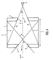
- the collimator 1 shown in Fig.1 forms part of an X-ray spectrometer (not completely shown) or an X-ray detector in which the X-rays 7 are conducted to a detection surface 2.
- the collimator I serves as an imaging element which operates purely in the transmission mode for high-energy electromagnetic rays, for example, for X-rays.
- the collimator I includes an entrance diaphragm 3 and an exit diaphragm 4 as well as a tube 5 which is situated therebetween and on the inner walls 6 of which reflection, scattering or other formation of secondary radiation of the electromagnetic rays propagating along the optical path 8 can take place.
- the diaphragms 3, 4 are provided with respective passage openings 3a, 4a which are constructed, for example, as a slit or as a passage opening bounded by a round contour.
- the edge zones 3b, 4b are angulated (angled) relative to the direction of propagation of the rays which in this case coincides with the optical axis 8.
- the X-ray optical elements 3,4 may be provided with different angulations in their edge zones 9, 10 as shown in Fig. 3 .
- the angle a of the edge zone 9 of the diaphragm 3 at the entrance side relative to the optical axis 8 is chosen to be such that a light beam 7a which is incident at a grazing angle would not be incident on the diaphragm 4 at the exit side, but on the zones 6 of the walls of the collimator. It is thus ensured that all rays which are not incident at a grazing angle but are reflected at an angle ⁇ relative to the surface of the edge zone 9 will be incident on the inner wall zones 6. The same holds for secondary rays emanating at an angle ⁇ .
- angles ⁇ of the edge zones 10 around the passage opening 4a of the X-ray optical element 4 at the exit side is such that a grazing ray 7b thereon just has to originate from the inner walls 6.
- the distance L between the entrance diaphragm 3 and the exit diaphragm 4 is chosen accordingly.
- the edge zones 9,10 are angulated each time on the full circle surrounding the passage zone 3a, 4a.
- the passage opening 3 a, 4a for example, in the case of a slit-shaped diaphragm, this is not absolutely necessary.
- the cross-section of the diaphragms opening 3a or 4a of the diaphragms 3 or 4 is shown in detail in Fig. 2 . It appears that a ray 11 penetrates the material of the diaphragm because it enters near the edge zone and hence cannot be completely absorbed by the locally remaining effective diaphragm thickness D. A similar situation occurs in the reverse circumstances as shown in Fig. 3 .
- the shortest ray 12 shown therein will emanate approximately perpendicularly to the angulated surface 9, 10; this path, however, is shorter than the path of the ray 11 in the reverse orientation of the diaphragm. This gives rise to more fluorescence and more scattering which could disturb the measurement.
- the collimator I may also be provided with a total of more than one diaphragm 3 at the entrance side and one diaphragm 4 at the exit side, that is, an arrangement of a plurality of diaphragms may be provided in the beam path 7; in that case each of said diaphragms or some of said diaphragms may be provided with angulated edge zones 9, 10.
- the X-ray optical elements 3, 4 together lead to a stronger enlargement of the emission angle ⁇ of scattered radiation and fluorescent radiation, emanating as secondary rays in the case of interaction between high-energy electromagnetic waves and matter, from the beam path 7 relative to the propagation direction 7 of the rays to be measured on the detector 2. Consequently, fewer of such disturbing rays appear on the detector window 2.
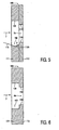
- Figs. 5 and 6 show X-ray optical elements 103, 104 which can be used as an alternative for the X-ray optical elements 3,4 in an example useful for understanding the invention but not forming an embodiment.
- a combination of diaphragms 103, 104 and diaphragms 3, 4, for example, within a collimator 1, is also for feasible an example useful for understanding the invention but not forming an embodiment.
- the diaphragms 3, 4 as well as 103, 104 can be selected and used also in an X-ray detector or spectrometer, as desired.
- Fig. 5 shows a diaphragm 103 which is composed of two assembled plate members 111, 112; such plate members 111, 112 may contain different materials.
- X-ray optical elements 3,4,103,104 of this kind are generally known for use in spectrometers, for example, for trace analysis, or in X-ray detectors, for example, for the acquisition of information concerning different absorption behaviors of X-rays in a spatially resolved manner.
- X-ray detectors or spectrometers or spectrometers utilizing similar high-energy radiation are generally known for use in spectrometers, for example, for trace analysis, or in X-ray detectors, for example, for the acquisition of information concerning different absorption behaviors of X-rays in a spatially resolved manner.
- a special application is found in X-ray detectors or spectrometers or spectrometers utilizing similar high-energy radiation.
Landscapes
- Physics & Mathematics (AREA)
- Spectroscopy & Molecular Physics (AREA)
- Engineering & Computer Science (AREA)
- General Engineering & Computer Science (AREA)
- High Energy & Nuclear Physics (AREA)
- Analysing Materials By The Use Of Radiation (AREA)
- X-Ray Techniques (AREA)
Priority Applications (1)
| Application Number | Priority Date | Filing Date | Title |
|---|---|---|---|
| EP02733099A EP1393327B1 (en) | 2001-06-01 | 2002-05-30 | X-ray optical system |
Applications Claiming Priority (4)
| Application Number | Priority Date | Filing Date | Title |
|---|---|---|---|
| EP01202113 | 2001-06-01 | ||
| EP01202113 | 2001-06-01 | ||
| PCT/IB2002/001965 WO2002097826A1 (en) | 2001-06-01 | 2002-05-30 | X-ray optical system |
| EP02733099A EP1393327B1 (en) | 2001-06-01 | 2002-05-30 | X-ray optical system |
Publications (2)
| Publication Number | Publication Date |
|---|---|
| EP1393327A1 EP1393327A1 (en) | 2004-03-03 |
| EP1393327B1 true EP1393327B1 (en) | 2010-08-25 |
Family
ID=8180414
Family Applications (1)
| Application Number | Title | Priority Date | Filing Date |
|---|---|---|---|
| EP02733099A Expired - Lifetime EP1393327B1 (en) | 2001-06-01 | 2002-05-30 | X-ray optical system |
Country Status (6)
| Country | Link |
|---|---|
| US (1) | US7194067B2 (enExample) |
| EP (1) | EP1393327B1 (enExample) |
| JP (1) | JP4315798B2 (enExample) |
| AT (1) | ATE479191T1 (enExample) |
| DE (1) | DE60237442D1 (enExample) |
| WO (1) | WO2002097826A1 (enExample) |
Families Citing this family (1)
| Publication number | Priority date | Publication date | Assignee | Title |
|---|---|---|---|---|
| JP2010277942A (ja) | 2009-06-01 | 2010-12-09 | Mitsubishi Electric Corp | Hモード型ドリフトチューブ線形加速器、およびその電場分布調整方法 |
Citations (2)
| Publication number | Priority date | Publication date | Assignee | Title |
|---|---|---|---|---|
| GB1136255A (en) * | 1966-03-28 | 1968-12-11 | Ass Elect Ind | Improvements relating to collimators |
| US3898455A (en) * | 1973-11-12 | 1975-08-05 | Jr Thomas C Furnas | X-ray monochromatic and focusing system |
Family Cites Families (7)
| Publication number | Priority date | Publication date | Assignee | Title |
|---|---|---|---|---|
| US2558492A (en) * | 1947-11-26 | 1951-06-26 | Hartford Nat Bank & Trust Co | Tubular x-ray diaphragm |
| FR2391699A1 (fr) * | 1976-04-09 | 1978-12-22 | Radiologie Cie Gle | Appareil de radiographie, notamment de mammographie |
| JPS5821583A (ja) * | 1981-07-31 | 1983-02-08 | Seiko Epson Corp | コリメ−タ− |
| US4506374A (en) * | 1982-04-08 | 1985-03-19 | Technicare Corporation | Hybrid collimator |
| US4809314A (en) * | 1986-02-25 | 1989-02-28 | General Electric Company | Method of aligning a linear array X-ray detector |
| US4910759A (en) * | 1988-05-03 | 1990-03-20 | University Of Delaware | Xray lens and collimator |
| US5682415A (en) * | 1995-10-13 | 1997-10-28 | O'hara; David B. | Collimator for x-ray spectroscopy |
-
2002
- 2002-05-30 EP EP02733099A patent/EP1393327B1/en not_active Expired - Lifetime
- 2002-05-30 AT AT02733099T patent/ATE479191T1/de not_active IP Right Cessation
- 2002-05-30 DE DE60237442T patent/DE60237442D1/de not_active Expired - Lifetime
- 2002-05-30 US US10/479,498 patent/US7194067B2/en not_active Expired - Lifetime
- 2002-05-30 WO PCT/IB2002/001965 patent/WO2002097826A1/en not_active Ceased
- 2002-05-30 JP JP2003500923A patent/JP4315798B2/ja not_active Expired - Fee Related
Patent Citations (2)
| Publication number | Priority date | Publication date | Assignee | Title |
|---|---|---|---|---|
| GB1136255A (en) * | 1966-03-28 | 1968-12-11 | Ass Elect Ind | Improvements relating to collimators |
| US3898455A (en) * | 1973-11-12 | 1975-08-05 | Jr Thomas C Furnas | X-ray monochromatic and focusing system |
Also Published As
| Publication number | Publication date |
|---|---|
| ATE479191T1 (de) | 2010-09-15 |
| WO2002097826A1 (en) | 2002-12-05 |
| US20040240620A1 (en) | 2004-12-02 |
| US7194067B2 (en) | 2007-03-20 |
| JP2004527773A (ja) | 2004-09-09 |
| EP1393327A1 (en) | 2004-03-03 |
| DE60237442D1 (de) | 2010-10-07 |
| JP4315798B2 (ja) | 2009-08-19 |
Similar Documents
| Publication | Publication Date | Title |
|---|---|---|
| JP6937380B2 (ja) | X線分光を実施するための方法およびx線吸収分光システム | |
| US6054712A (en) | Inspection equipment using small-angle topography in determining an object's internal structure and composition | |
| AU2011227502B2 (en) | Multiple screen detection systems | |
| US8148693B2 (en) | Multiple screen detection systems | |
| JP5116014B2 (ja) | 小角広角x線測定装置 | |
| Flippo et al. | Development of a Big Area BackLighter for high energy density experiments | |
| UA59495C2 (uk) | Рентгенівський вимірювально-випробувальний комплекс | |
| RU2001119066A (ru) | Рентгеновский измерительно-испытательный комплекс | |
| US3143651A (en) | X-ray reflection collimator adapted to focus x-radiation directly on a detector | |
| EP0898704A1 (en) | Inspection equipment using small-angle topography in determining an object's internal structure and composition | |
| JP3260459B2 (ja) | 弾性的散乱x線量のパルス伝送スペクトルを測定する装置 | |
| US20120294426A1 (en) | Compact x-ray analysis system | |
| EP3661421B1 (en) | Convergent x-ray imaging device and method | |
| US8416921B2 (en) | X-ray convergence element and X-ray irradiation device | |
| EP1393327B1 (en) | X-ray optical system | |
| JPH0954050A (ja) | X線小角散乱装置 | |
| RU2239822C2 (ru) | Рентгеновский микроскоп | |
| RU2072515C1 (ru) | Многоканальный рентгеновский анализатор элементного состава | |
| JP3529068B2 (ja) | X線小角散乱装置 | |
| JP5646147B2 (ja) | 二次元分布を測定する方法及び装置 | |
| EP1434983B1 (en) | Limiting device for electromagnetic radiation, notably in an analysis device | |
| RU2602433C2 (ru) | Рентгеновский источник с оптической индикацией | |
| RU2006799C1 (ru) | Гониофотометр | |
| JP2001074892A (ja) | コリメータ及びx線装置 | |
| Priedhorsky et al. | Laué diffraction hard x‐ray spectrometer for laser fusion diagnostics |
Legal Events
| Date | Code | Title | Description |
|---|---|---|---|
| PUAI | Public reference made under article 153(3) epc to a published international application that has entered the european phase |
Free format text: ORIGINAL CODE: 0009012 |
|
| 17P | Request for examination filed |
Effective date: 20031211 |
|
| AK | Designated contracting states |
Kind code of ref document: A1 Designated state(s): AT BE CH CY DE DK ES FI FR GB GR IE IT LI LU MC NL PT SE TR |
|
| 17Q | First examination report despatched |
Effective date: 20070425 |
|
| GRAP | Despatch of communication of intention to grant a patent |
Free format text: ORIGINAL CODE: EPIDOSNIGR1 |
|
| GRAS | Grant fee paid |
Free format text: ORIGINAL CODE: EPIDOSNIGR3 |
|
| GRAA | (expected) grant |
Free format text: ORIGINAL CODE: 0009210 |
|
| AK | Designated contracting states |
Kind code of ref document: B1 Designated state(s): AT BE CH CY DE DK ES FI FR GB GR IE IT LI LU MC NL PT SE TR |
|
| REG | Reference to a national code |
Ref country code: GB Ref legal event code: FG4D |
|
| REG | Reference to a national code |
Ref country code: CH Ref legal event code: EP |
|
| REG | Reference to a national code |
Ref country code: IE Ref legal event code: FG4D |
|
| REF | Corresponds to: |
Ref document number: 60237442 Country of ref document: DE Date of ref document: 20101007 Kind code of ref document: P |
|
| REG | Reference to a national code |
Ref country code: NL Ref legal event code: T3 |
|
| PG25 | Lapsed in a contracting state [announced via postgrant information from national office to epo] |
Ref country code: AT Free format text: LAPSE BECAUSE OF FAILURE TO SUBMIT A TRANSLATION OF THE DESCRIPTION OR TO PAY THE FEE WITHIN THE PRESCRIBED TIME-LIMIT Effective date: 20100825 Ref country code: FI Free format text: LAPSE BECAUSE OF FAILURE TO SUBMIT A TRANSLATION OF THE DESCRIPTION OR TO PAY THE FEE WITHIN THE PRESCRIBED TIME-LIMIT Effective date: 20100825 |
|
| PG25 | Lapsed in a contracting state [announced via postgrant information from national office to epo] |
Ref country code: PT Free format text: LAPSE BECAUSE OF FAILURE TO SUBMIT A TRANSLATION OF THE DESCRIPTION OR TO PAY THE FEE WITHIN THE PRESCRIBED TIME-LIMIT Effective date: 20101227 Ref country code: CY Free format text: LAPSE BECAUSE OF FAILURE TO SUBMIT A TRANSLATION OF THE DESCRIPTION OR TO PAY THE FEE WITHIN THE PRESCRIBED TIME-LIMIT Effective date: 20100825 |
|
| PG25 | Lapsed in a contracting state [announced via postgrant information from national office to epo] |
Ref country code: BE Free format text: LAPSE BECAUSE OF FAILURE TO SUBMIT A TRANSLATION OF THE DESCRIPTION OR TO PAY THE FEE WITHIN THE PRESCRIBED TIME-LIMIT Effective date: 20100825 Ref country code: GR Free format text: LAPSE BECAUSE OF FAILURE TO SUBMIT A TRANSLATION OF THE DESCRIPTION OR TO PAY THE FEE WITHIN THE PRESCRIBED TIME-LIMIT Effective date: 20101126 Ref country code: SE Free format text: LAPSE BECAUSE OF FAILURE TO SUBMIT A TRANSLATION OF THE DESCRIPTION OR TO PAY THE FEE WITHIN THE PRESCRIBED TIME-LIMIT Effective date: 20100825 |
|
| PG25 | Lapsed in a contracting state [announced via postgrant information from national office to epo] |
Ref country code: DK Free format text: LAPSE BECAUSE OF FAILURE TO SUBMIT A TRANSLATION OF THE DESCRIPTION OR TO PAY THE FEE WITHIN THE PRESCRIBED TIME-LIMIT Effective date: 20100825 |
|
| PG25 | Lapsed in a contracting state [announced via postgrant information from national office to epo] |
Ref country code: IT Free format text: LAPSE BECAUSE OF FAILURE TO SUBMIT A TRANSLATION OF THE DESCRIPTION OR TO PAY THE FEE WITHIN THE PRESCRIBED TIME-LIMIT Effective date: 20100825 |
|
| PG25 | Lapsed in a contracting state [announced via postgrant information from national office to epo] |
Ref country code: ES Free format text: LAPSE BECAUSE OF FAILURE TO SUBMIT A TRANSLATION OF THE DESCRIPTION OR TO PAY THE FEE WITHIN THE PRESCRIBED TIME-LIMIT Effective date: 20101206 |
|
| PLBE | No opposition filed within time limit |
Free format text: ORIGINAL CODE: 0009261 |
|
| STAA | Information on the status of an ep patent application or granted ep patent |
Free format text: STATUS: NO OPPOSITION FILED WITHIN TIME LIMIT |
|
| 26N | No opposition filed |
Effective date: 20110526 |
|
| REG | Reference to a national code |
Ref country code: DE Ref legal event code: R097 Ref document number: 60237442 Country of ref document: DE Effective date: 20110526 |
|
| PG25 | Lapsed in a contracting state [announced via postgrant information from national office to epo] |
Ref country code: MC Free format text: LAPSE BECAUSE OF NON-PAYMENT OF DUE FEES Effective date: 20110531 |
|
| REG | Reference to a national code |
Ref country code: CH Ref legal event code: PL |
|
| PG25 | Lapsed in a contracting state [announced via postgrant information from national office to epo] |
Ref country code: CH Free format text: LAPSE BECAUSE OF NON-PAYMENT OF DUE FEES Effective date: 20110531 Ref country code: LI Free format text: LAPSE BECAUSE OF NON-PAYMENT OF DUE FEES Effective date: 20110531 |
|
| REG | Reference to a national code |
Ref country code: IE Ref legal event code: MM4A |
|
| PG25 | Lapsed in a contracting state [announced via postgrant information from national office to epo] |
Ref country code: IE Free format text: LAPSE BECAUSE OF NON-PAYMENT OF DUE FEES Effective date: 20110530 |
|
| PG25 | Lapsed in a contracting state [announced via postgrant information from national office to epo] |
Ref country code: LU Free format text: LAPSE BECAUSE OF NON-PAYMENT OF DUE FEES Effective date: 20110530 |
|
| PG25 | Lapsed in a contracting state [announced via postgrant information from national office to epo] |
Ref country code: TR Free format text: LAPSE BECAUSE OF FAILURE TO SUBMIT A TRANSLATION OF THE DESCRIPTION OR TO PAY THE FEE WITHIN THE PRESCRIBED TIME-LIMIT Effective date: 20100825 |
|
| REG | Reference to a national code |
Ref country code: FR Ref legal event code: PLFP Year of fee payment: 14 |
|
| REG | Reference to a national code |
Ref country code: FR Ref legal event code: PLFP Year of fee payment: 15 |
|
| REG | Reference to a national code |
Ref country code: FR Ref legal event code: PLFP Year of fee payment: 16 |
|
| REG | Reference to a national code |
Ref country code: DE Ref legal event code: R082 Ref document number: 60237442 Country of ref document: DE Representative=s name: PATENTANWAELTE RUFF, WILHELM, BEIER, DAUSTER &, DE Ref country code: DE Ref legal event code: R081 Ref document number: 60237442 Country of ref document: DE Owner name: MALVERN PANALYTICAL B.V., NL Free format text: FORMER OWNER: PANALYTICAL B.V., ALMELO, NL |
|
| REG | Reference to a national code |
Ref country code: NL Ref legal event code: HC Owner name: MALVERN PANALYTICAL B.V.; NL Free format text: DETAILS ASSIGNMENT: CHANGE OF OWNER(S), CHANGE OF OWNER(S) NAME; FORMER OWNER NAME: PANALYTICAL B.V. Effective date: 20180206 |
|
| REG | Reference to a national code |
Ref country code: FR Ref legal event code: PLFP Year of fee payment: 17 |
|
| REG | Reference to a national code |
Ref country code: FR Ref legal event code: CD Owner name: MALVERN PANALYTICAL B.V., NL Effective date: 20180529 |
|
| PGFP | Annual fee paid to national office [announced via postgrant information from national office to epo] |
Ref country code: NL Payment date: 20190515 Year of fee payment: 18 |
|
| PGFP | Annual fee paid to national office [announced via postgrant information from national office to epo] |
Ref country code: DE Payment date: 20190514 Year of fee payment: 18 |
|
| PGFP | Annual fee paid to national office [announced via postgrant information from national office to epo] |
Ref country code: FR Payment date: 20190410 Year of fee payment: 18 |
|
| PGFP | Annual fee paid to national office [announced via postgrant information from national office to epo] |
Ref country code: GB Payment date: 20190529 Year of fee payment: 18 |
|
| REG | Reference to a national code |
Ref country code: DE Ref legal event code: R119 Ref document number: 60237442 Country of ref document: DE |
|
| REG | Reference to a national code |
Ref country code: NL Ref legal event code: MM Effective date: 20200601 |
|
| PG25 | Lapsed in a contracting state [announced via postgrant information from national office to epo] |
Ref country code: NL Free format text: LAPSE BECAUSE OF NON-PAYMENT OF DUE FEES Effective date: 20200601 |
|
| GBPC | Gb: european patent ceased through non-payment of renewal fee |
Effective date: 20200530 |
|
| PG25 | Lapsed in a contracting state [announced via postgrant information from national office to epo] |
Ref country code: GB Free format text: LAPSE BECAUSE OF NON-PAYMENT OF DUE FEES Effective date: 20200530 Ref country code: FR Free format text: LAPSE BECAUSE OF NON-PAYMENT OF DUE FEES Effective date: 20200531 |
|
| PG25 | Lapsed in a contracting state [announced via postgrant information from national office to epo] |
Ref country code: DE Free format text: LAPSE BECAUSE OF NON-PAYMENT OF DUE FEES Effective date: 20201201 |