EP1392549B1 - Abdichteinrichtung einer leitungsverbindung - Google Patents
Abdichteinrichtung einer leitungsverbindung Download PDFInfo
- Publication number
- EP1392549B1 EP1392549B1 EP02754622A EP02754622A EP1392549B1 EP 1392549 B1 EP1392549 B1 EP 1392549B1 EP 02754622 A EP02754622 A EP 02754622A EP 02754622 A EP02754622 A EP 02754622A EP 1392549 B1 EP1392549 B1 EP 1392549B1
- Authority
- EP
- European Patent Office
- Prior art keywords
- wall portion
- expansion
- sealing device
- interior
- tube head
- Prior art date
- Legal status (The legal status is an assumption and is not a legal conclusion. Google has not performed a legal analysis and makes no representation as to the accuracy of the status listed.)
- Expired - Lifetime
Links
- 238000007789 sealing Methods 0.000 title claims abstract description 81
- 230000002093 peripheral effect Effects 0.000 claims abstract description 12
- 230000001681 protective effect Effects 0.000 claims description 17
- 210000002105 tongue Anatomy 0.000 claims description 13
- 238000007572 expansion measurement Methods 0.000 claims 3
- 239000012858 resilient material Substances 0.000 claims 2
- 239000000463 material Substances 0.000 claims 1
- 230000007480 spreading Effects 0.000 description 53
- 238000003892 spreading Methods 0.000 description 53
- 238000004519 manufacturing process Methods 0.000 description 5
- 230000000694 effects Effects 0.000 description 4
- 239000011324 bead Substances 0.000 description 3
- 238000009434 installation Methods 0.000 description 3
- 238000000034 method Methods 0.000 description 3
- 230000008569 process Effects 0.000 description 3
- 238000003780 insertion Methods 0.000 description 2
- 230000037431 insertion Effects 0.000 description 2
- 238000010137 moulding (plastic) Methods 0.000 description 2
- 230000000712 assembly Effects 0.000 description 1
- 238000000429 assembly Methods 0.000 description 1
- 230000004888 barrier function Effects 0.000 description 1
- 238000005452 bending Methods 0.000 description 1
- 230000008901 benefit Effects 0.000 description 1
- 230000015572 biosynthetic process Effects 0.000 description 1
- 230000007812 deficiency Effects 0.000 description 1
- 230000005489 elastic deformation Effects 0.000 description 1
- 239000013013 elastic material Substances 0.000 description 1
- 230000002349 favourable effect Effects 0.000 description 1
- 238000005304 joining Methods 0.000 description 1
- 239000012528 membrane Substances 0.000 description 1
- 230000035515 penetration Effects 0.000 description 1
- XLYOFNOQVPJJNP-UHFFFAOYSA-N water Substances O XLYOFNOQVPJJNP-UHFFFAOYSA-N 0.000 description 1
Images




Classifications
-
- B—PERFORMING OPERATIONS; TRANSPORTING
- B60—VEHICLES IN GENERAL
- B60R—VEHICLES, VEHICLE FITTINGS, OR VEHICLE PARTS, NOT OTHERWISE PROVIDED FOR
- B60R16/00—Electric or fluid circuits specially adapted for vehicles and not otherwise provided for; Arrangement of elements of electric or fluid circuits specially adapted for vehicles and not otherwise provided for
- B60R16/02—Electric or fluid circuits specially adapted for vehicles and not otherwise provided for; Arrangement of elements of electric or fluid circuits specially adapted for vehicles and not otherwise provided for electric constitutive elements
- B60R16/0207—Wire harnesses
- B60R16/0215—Protecting, fastening and routing means therefor
- B60R16/0222—Grommets
Definitions
- connecting lines In motor vehicles often have to between the body and the vehicle doors are laid connecting lines, the outward, i. opposite the environment, sealed have to be.
- the connecting lines at the passage points opposite the body and the door to be sealed will be the relevant section of the connecting line between the body and the door surrounded by a bellows. This bellows in turn needs to face the body and the door to be sealed.
- the end portion of the bellows is at the passage opening in a sense, tied in by the one to the Groove subsequent outer part of the end portion elastic is compressed and through the passage opening is inserted through it. After the end section has relaxed, lies on each of the two bead parts his facing edge region of the passage opening on Component on. In addition, the base of the groove is more or less closely to the inner peripheral surface of the passage opening at.
- This known sealing device has the great disadvantage that under elastic deformation, at least one Part of the end portion of the bellows, at the passage opening must be knotted. These are time consuming and very cumbersome work that turns out can not be automated.
- the tightness of such Sealing device depends very much on the manufacturing tolerances the parts to be joined together. If for example, the distance of the groove walls greater than that Thickness of the component is at least the axial abutment the groove walls on the component and thus the sealing effect of Sealing device questioned. The same applies to the radial contact of the groove bottom on the inner edge surface the passage opening.
- the passage opening has an outline that is larger than that of the groove bottom is, the end portion of the bellows is not on the inner edge surface of the passage opening of the component at. In particularly unfavorable cases both can Deficiencies occur at the same time, which means no Sealing effect is achieved more.
- the biggest disadvantage is the lack of parallelism Contact surface of the end portion on the one hand and the edge portion on the other hand.
- the edge section The component may be very wavy in the circumferential direction.
- Another disadvantage of this sealing device is in that dimensional deviations between the thickness of the component and the distance between the abutment surface of the end portion the bellows and the contact surface of the Holding clips can also occur, which is also a dense Prevent installation of the contact surface of the bellows on the component can.
- Such a sealing device is from the US-5,280,134-A known.
- Your bellows only points a circumferential sealing lip on the front of the Component rests in the axial direction.
- the end section the bellows is with a circumferential flange-like Housing connected, extending through the passage opening extends through the component and there at two each other opposite circumferential points depending on a recess having.
- This is a wedge-shaped lock body means a bending joint pivotally arranged in the manner that he when inserting the flange-like housing in the Passage opening of the component evades radially inwardly and then returns to its original position.
- both locking body pivoted further outwards, so that her back surface at the edge of the passage opening of the component and thereby the bellows on Component locked. Because of the large tolerances of all Components is a dense system of the circumferential sealing lip difficult to reach the bellows on the component. A radially acting seal is not available, certainly not one with a radial Spreading process.
- the invention is based on the object, a sealing device a line connection between two relative mutually movable components, in particular a body and a door, to create, at the time of joining the parts have a better sealing effect than the is ensured known sealing devices.
- a hose head is present, the one in the circumferential direction having a ring-shaped self-contained wall section, the one outwardly directed circumferential sealing surface whose outer contour on the Outline of the passage opening is tuned, and thereby, that in the hose head with a spreading device outer abutment surfaces for the wall portion with the sealing surface exists, and in that an actuator body is present, by means of which the spreading device can be activated after insertion of the hose head into the passage opening of the component the wall portion of the hose head with the sealing surface taking advantage of its elasticity on the inner Edge surface of the passage opening are pressed. So can a very good seal between the hose head and the component can be achieved. This is largely independent from the usual manufacturing tolerances of each other interacting parts.
- the inner Edge surface of the passage opening markedly increased, so that at a given spreading force of the spreading device the sealing surface of the hose head less stressed becomes and thereby.the durability of the connection and the tightness is improved.
- a stop created for the hose head, which in the assembly of Sealing device automatically, d. H. without the intervention of the installation personnel, for the correct positioning of the first Wall section with the sealing surface in the plane of the Component ensures.
- the flange forms a certain barrier against the penetration of debris and from larger amounts of water to the actual sealing point. This is achieved by a circumferential sealing lip on Flange part still supported.
- the spreading device already when assembling the parts in the correct position in the plane of the wall section with the Sealing surface brought and also held there, when the actuator body relative to the spreading device is moved.
- Claim 5 is a particularly stable stopper body also created for a torsion-free alignment the spreading device provides. Due to the closed ring shape The stopper is particularly resistant. The tuned to the annular stop body Wall section of the hose head ensures, without further notice For the correct positioning of the stop body and thus also the spreading device.
- the stopper body also held in the rearward direction, so that he always keeps his right position.
- the second provides Flange part of the hose head that the in the Hose head inserted parts of the sealing device also be held in forward direction, so they always maintain their correct position.
- a spreading device created that also run larger Sp Schwarzwege can and therefore larger tolerances of the outline bridge the passage opening of the component easier can.
- the mutually cooperating parts of the sealing device be locked against each other, so that an unintentional Release the sealing device and thus the Hose head of the connecting line practically impossible is.
- a plug 20 can be seen, which is connected to a invisible connecting line is connected, the is surrounded by a protective tube 21 and therefore not is visible.
- the protective tube 21 goes in at its end a hose head 22, the part of a sealing device 23 is ( Figures 3 and 4). This ensures the watertight connection of the connecting line to a Component 24, which is movable relative to another component is at the other end of the connecting line same or similar way is connected. Since the Tube head 22 is part of the protective tube 21 is to better distinguish these parts of the protective tube 21 in the narrow sense of the word in the following also referred to as the middle part of the protective tube 21.
- the main assemblies or parts of the sealing device 23 are the tube head 22, a spreading device 25, a Stopper body 26, an actuator body 27 and two Locking devices 28 and 29.
- the component 24 is for example a wall of the body or a door of a motor vehicle.
- the component 24 has a passage opening 31 for the connecting line.
- the passage opening 31 has a certain outline, generally a circular or a long-round Course has.
- the component 24 is expediently with a provided by a deep-drawing process generated drawing edge 32. Its inside is at least approximately rectangular aligned with the edge region of the passage opening 31 and forms an inner edge surface 33, the one has certain axial extent.
- the passage opening can also be made by a simple Stamping process are generated, the inner edge surface then has only an axial extent equal to the thickness of the Component is. That would be for the sealing device 23 less favorable.
- the protective tube 21 is designed in the manner of a corrugated membrane, to give him as much flexibility as possible. Its tube head 22 is itself a part of Sealing device 23. In addition, he still takes more parts of the sealing device.
- Wall sections extend partly in at least approximately axial direction and partly in at least approximately, radial direction. They are in the circumferential direction ring-shaped self-contained and close in axial Towards each other.
- the first wall portion 41 of the hose head 22 is in axial region of the inner edge surface 33 of the passage opening 31 positioned.
- the axial extent of the Wall section 41 is larger than the axial extent the inner edge surface 33.
- the outer contour of the Wall section 41 is on the outline of the inner Edge surface 33 is tuned such that the first wall section 41 in the initial state or idle state in the Passage opening 31 can be inserted and he all the way to the inner edge surface 33 of the passage opening 31 comes up.
- This part of the wall section 41 serves the sealing device as a circumferential sealing surface 51st
- the spreading device 25 In the axial region of the sealing surface 51 is on the Inside the first wall portion 41, the spreading device 25 arranged. Next to it is in the axial area of the third wall portion 43 of the stopper body 26 is arranged. He is permanently with the spreading device 25 connected and together with it forms a structural unit (Fig. 6), which is produced as a plastic molding.
- the spreading device has several in the circumferential direction juxtaposed spreading elements 52 and 53. They are each through a pair of elastic links 54 and 55 connected to the stopper body 26.
- the links 54 and 55 are as flat and wide leaf springs formed. As a result, the spreading elements 52 and 53, although yielding in the radial direction, in the axial direction but immovable with the Stop body 26 connected.
- both the inner edge surface 33 of the passage opening 31 as well as the Outside and the inside of the first wall section 41, the spreading elements 52 are on the long sides just trained and the spreading elements 53 to the Narrow sides arcuately curved.
- the spreading elements 52 On its outer side, the spreading elements 52 have a outer abutment surface 56 and the spreading elements 53 a outer contact surface 57 on. Point on the inside the straight expansion elements 52 an inner bearing surface 58th and the curved spreading members 53 have an inner abutment surface 59 on.
- a pressure body 61 is arranged between the spreading device 25 and the first wall section 41 the hose head 22 . He is ring-shaped in itself and made of an elastic Material produced.
- the outer contact surfaces 56 and 57 of the spreading elements 52 and 53 are located on this pressure body 61 directly which is why they point to the inside of the first wall section 41 act only indirectly.
- the pressure hull 61 which are also referred to as upholstery body could, contributes to tolerances of the component 24, the first wall portion 41, the spreading device 25 and compensate for the actuator 27 and also the unavoidable circumferential gaps 62 between each two adjacent spreader 52 and / or 53 to bridge.
- FIG. 6 and FIG. 9 the stopper body 26 by a self-contained Ring formed.
- the Spreading elements 52 and 53 of the spreading device 25 forms the stopper body 26 at the same time a support body, the Spreading elements 52 and 53 via the connecting links 54 or holds 55 in the correct axial position.
- the annular stopper body 26 is in the radial direction in the Aufriss Scheme the flange 42 of the hose body 22, where he will invest at the latest when the actuator body 27 a forward facing axial force is exerted on the expansion body 25. there supports the stopper body 26 via the flange 42nd on the component 24 from.
- the radial extent of the flange 42, the axial Extension of the third wall portion 43 and the radial Extension of the fourth wall portion 44 of the hose head 22 are on the appropriate dimensions of the Stopper body 26 tuned so that he in the of them circumscribed interior can be accommodated and held.
- the wall sections of the hose head 22 are sufficient elastic, so that the stopper body 26 in this interior can be brought into it, the clipped in a sense becomes.
- the plug is and the actuating device combined to form a structural unit, at the front in the direction of insertion, in Fig. 10 right-most part, the plug 20 forms and the rear part forms the operating body 27.
- This unit is as a common plastic molding produced.
- the formation of the plug 20 and its accessories, such as a bar with plug pins 63 depends on the requirements of the electrical Line connection and the associated socket with the continuing lines. As it is Usually they are standard parts, they are at least for Part of the design and dimensions of the remaining parts of the sealing device.
- the plug 20 and the subsequent actuating body 27 are in the hose head 22 of the spreading elements 52 and 53 of the spreading device 25 guided axially displaceable.
- the outer contact surfaces 64 and 65 on the actuator body 27 on the one hand and the inner abutment surfaces 58 and 59 on the spreader, on the other hand, are both in the longitudinal direction as well as in the circumferential direction in such a way tuned to each other, that in the operating position of the actuating body, the mutually associated contact surfaces cover each other at least in part and that in the initial position of the actuator body 27, the one another associated contact surfaces are disengaged.
- the actuator body 27 despite its excess in the spreading device 25 can be inserted to the Spreading elements 52 and 53 to spread apart are the actuator body 27 at the front end of the outer Abutment surfaces 64 and 65 ramp surfaces 66 and 67, respectively, whose height is greater than the oversize or spread "s is.
- the axial extent of the compensating strips 72nd and 73 is at least approximately equal to that of outer abutment surfaces of the expansion elements 52 and 53.
- Their outer sides have the compensating strips 72 and 73 an outer bearing surface 74 and 75, respectively, on the outer Contact surface of the two adjacent expansion elements so is agreed that the outer contact surfaces 74 and 75 the compensation strips a continuation of the outer contact surfaces 56 and 57 of the expansion elements 52 and 53 form.
- FIGS. 14 and 15 the FIG front end of the spreading device 25, the first locking device 28 connected by means of the entire Sealing device on the component 24 can be locked.
- the locking device 28 is characterized by several at Circumferentially distributed arranged, locking lugs 76 formed whose locking surface 77 is turned backwards.
- the locking lugs 76 are arranged in the axial direction at a location beyond the inner peripheral surface 33 of the passage opening 31 of the component 24 is located.
- the locking lugs 76 have such a radial extent that they in the initial state or idle state of the spreading device 25 within the outline of the passage opening 31 stand (Fig. 14) and that they are in the operating state of Spreading device 25 into the edge region of the passage opening 31 protrude. (Fig. 15).
- the Locking lugs 76 at the front end of the straight expansion elements 52 arranged. They are molded to it.
- the wall portion 41 in the region of Locking lug 76 a recess 81 which on the locking lug 76 is tuned so that the locking lug 76 in Radial direction can escape to the outside.
- the locking device 29 has two pairs of locking notches 83 and two pairs of locking lugs 84.
- the bars notches 83 are through the one wall portion of a recess a bolt tongue 85 formed on the stopper body 26th is formed and thus also part of the spreading device 25th is.
- the locking lugs 84 are arranged on locking tongues 86, extending from the rear end of the actuator body 27 extend axially away.
- the locking notches 83 and the locking lugs 84 are in axial Direction arranged so that they are in the starting position of the actuator body 27 are disengaged and that they in the operating position of the actuating body 27 with each other interact.
Landscapes
- Engineering & Computer Science (AREA)
- Mechanical Engineering (AREA)
- Connector Housings Or Holding Contact Members (AREA)
- Quick-Acting Or Multi-Walled Pipe Joints (AREA)
- Gasket Seals (AREA)
- Cable Accessories (AREA)
- Connections Arranged To Contact A Plurality Of Conductors (AREA)
- Coupling Device And Connection With Printed Circuit (AREA)
- Seal Device For Vehicle (AREA)
- Selective Calling Equipment (AREA)
Description
Es zeigen:
- Fig. 1
- eine Seitenansicht eines Steckers einer Verbindungsleitung mit einem Schutzschlauch und einer Abdichteinrichtung gemäß der Erfindung;
- Fig. 2
- eine teilweise geschnitten dargestellte Seitenansicht des Schutzschlauches;
- Fig. 3 und 4
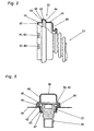
- je einen ausschnittweise dargestellten Längsschnitt der Abdichteinrichtung nach der Schnittverlaufslinie A - A in Fig. 1, in der Ausgangsstellung bzw. der Betriebstellung der Teile;
- Fig. 5
- einen Querschnitt der Abdichteinrichtung nach der Schnittverlaufslinie B - B in Fig. 1, in der - Betriebsstellung entsprechend Fig. 4;
- Fig. 6
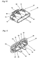
- eine perspektivische Ansicht einer Baueinheit aus Spreizvorrichtung und Anschlagkörper der Abdichteinrichtung;
- Fig. 7 bis 9
- eine Seitenansicht bzw. eine Stirnansicht bzw. eine Untersicht der Baueinheit nach Fig. 6;
- Fig. 10
- eine perspektivische Ansicht eines Steckerkörpers und zugleich eines Betätigungskörpers der Abdichteinrichtung;
- Fig. 11 bis 13
- eine Seitenansicht bzw. eine Stirnansicht bzw. eine Untersicht des Steckerkörpers und Betätigungskörpers nach Fig. 10;
- Fig. 14 und 15
- je einen ausschnittweise dargestellten Längsschnitt der Abdichteinrichtung nach der Schnittverlaufslinie C - C in Fig. 1, in der Ausgangsstellung bzw. der Betriebstellung der Teile.
- 20
- Stecker
- 21
- Schutzschlauch
- 22
- Schkauchkopf
- 23
- Abdichteinrichtung
- 24
- Bauteil
- 25
- Spreizvorrichtung
- 26
- Anschlagkörper
- 27
- Betätigungskörper
- 28
- Verriegelungsvorrichtung
- 29
- Verriegelungsvorrichtung
- 31
- Durchlassöffnung
- 32
- Ziehrand
- 33
- innere Randfläche
- 41
- erster Wandabschnitt
- 42
- zweiter Wandabschnitt
- 43
- dritter Wandabschnitt
- 44
- vierter Wandabschnitt
- 45
- fünfter Wandabschnitt
- 46
- sechster Wandabschnitt
- 47
- siebter Wandabschnitt
- 48
- Dichtlippe
- 51
- Dichtungsfläche
- 52
- Spreizelement, gerade
- 53
- Spreizelement, gekrümmt
- 54
- Verbindungsglieder
- 55
- Verbindungsglieder
- 56
- äußere Anlagefläche
- 57
- äußere Anlagefläche
- 58
- innere Anlagefläche
- 59
- innere Anlagefläche
- 61
- Druckkörper
- 62
- Umfangslücken
- 63
- Steckerstifte
- 64
- äußere Anlageflächen
- 65
- äußere Anlageflächen
- 66
- Rampenflächen
- 67
- Rampenflächen
- 68
- Umfangslücken
- 69
- Umfangslücken
- 72
- Ausgleichsleisten
- 73
- Ausgleichsleisten
- 74
- äußere Anlageflächen
- 75
- äußere Anlageflächen
- 76
- Riegelnasen
- 77
- Riegelfläche
- 78
- Betätigungzunge
- 81
- Ausnehmung
- 82
- Ausnehmung
- 83
- Riegelkerben
- 84
- Riegelnasen
- 85
- Riegelzunge
- 86
- Riegelzunge
- 87
- Rampenfläche
Claims (16)
- Abdichteinrichtung einer Leitungsverbindung zwischen zwei relativ zu einander bewegbaren Bauteilen, insbesondere einer Karosserie und einer Tür, mit den Merkmalen:das eine Bauteil (24) dieser beiden Bauteile weist eine ringförmig geschlossene Durchlassöffnung (31) für eine Verbindungsleitung auf,die Durchlassöffnung (31) hat eine vorgegebene Umrißlinie und eine zumindest annähernd rechtwinklig zum Randbereich der Durchlaßöffnung (31) ausgerichtete innere Randfläche (33),es ist ein Schutzschlauch (21) vorhanden, der in seinem Inneren die Verbindungsleitung aufnimmt,der Schutzschlauch (21) weist wenigstens an seinem einen Ende einen Schlauchkopf (22) für den Anschluß an dem Bauteil (24) auf,der Schlauchkopf (22) weist wenigstens einen in Umfangsrichtung ringförmig in sich geschlossenen Wandabschnitt (41) auf,dieser Wandabschnitt (41) weist eine nach außen - gerichtete umlaufende Dichtungsfläche (51) auf,deren äußere Umrißlinie auf die innere Umrißlinie der Durchlassöffnung (31) abgestimmt ist undderen axiale Erstreckung mindestens gleich der axialen Erstreckung der Randfläche (33) der Durchlassöffnung (31) ist,im Schlauchkopf (22) ist eine Spreizvorrichtung (25) mit einer oder mehreren äußeren Anlageflächen (52; 53) vorhanden,die im Axialbereich der Dichtungsfläche (51) des Wandabschnittes (41) des Schlauchkopfes (22) angeordnet sind,die im Ruhezustand der Spreizvorrichtung (25) zumindest annähernd an die Innenseite des Wandabschnittes (41) heranreichen unddie bei einer Betätigung der Spreizvorrichtung (25) durch einen Betätigungskörper (27) zumindest annähernd radial auswärts bewegbar und/oder verformbar sind,der Betätigungskörper (27) ist,im Inneren des Schlauchkopfes (22) angeordnet undin axialer Richtung verschiebbar geführt,die Spreizvorrichtung (25) weist wenigstens eine innere Anlagefläche (58; 59) und der Betätigungskörper (27) weist wenigstens eine äußere Anlagefläche (64; 65) auf,die in der Betriebsstellung des Betätigungskörpers (27) einander zumindest zum Teil überdecken unddie in der Ausgangsstellung des Betätigungskörpers (27) außer Eingriff sind,in Bezug auf eine gedachte Längsachse des Schlauchkopfes (22) ist der radiale Abstand der äußeren Anlagefläche (64; 65) des Betätigungskörpers (27) um ein vorgegebenes Spreizmaß (s) größer als der radiale Abstand der damit zusammenwirkenden inneren Anlagefläche (58; 59) der Spreizvorrichtung (25) in deren Ausgangsstellung,an demjenigen Ende der äußeren Anlagefläche (64; 65) des Betätigungskörpers (27) und/oder der inneren Anlagefläche der Spreizvorrichtung, das in der Ausgangsstellung des Betätigungskörpers (27) der jeweils anderen Anlagefläche (58; 59) zugekehrt ist, ist eine Rampenfläche (66 67) vorhanden, deren Höhe größer als das Spreizmaß (s) ist.
- Abdichteinrichtung nach Anspruch 1, mit den weiteren Merkmalen:die innere Randfläche (33) der Durchlassöffnung (31) des Bauteils (24) wird durch die Innenfläche eines Bördelrandes oder eines in axialer Richtung tiefgezogenen Ziehrandes (32) gebildet,der Wandabschnitt (41) des Schlauchkopfes (22) mit der Dichtungsfläche (51) hat eine axiale Erstrekkung, die mindests gleich derjenigen des Bördelrandes oder Ziehrandes (32) ist.
- Abdichteinrichtung nach einem der vorangehenden Ansprüche, mit den weiteren Merkmalen:an den ersten Wandabschnitt (41) des Schlauchkopfes (21) mit der Dichtungsfläche (51) schließt auf der dem Mittelteil des Schutzschlauches (21 ) zugekehrten Seite ein zweiter Wandabschnitt (42) an,der radial auswärts gerichtet ist,der flanschartig ausgebildet ist und dadurch einen Flanschteil (42) bildet,der zumindest annähernd parallel zu dem ihm benachbarten Randbereich des Bauteils (24) verläuft undder eine vorgegebene radiale Erstreckung hat,vorzugsweise ist an der dem Bauteil (24) zugekehrten Seite des Flanschteils (42) im Randbereich der Durchlassöffnung (31) eine umlaufende Dichtlippe (48) angeordnet, insbesondere daran angeformt.
- Abdichteinrichtung nach Anspruch 3, mit den weiteren Merkmalen:im Schlauchkopf (22) ist wenigstens ein Anschlagkörper (26) vorhanden,der auf der dem Mittelteil des Schutzschlauches (22) zugekehrten Seite des Flanschteils (42) angeordnet ist,der in radialer Richtung zumindest zum Teil in den Aufrißbereich des Flanschteils (42) hineinragt undder mit der Spreizvorrichtung (25) in axialer Richtung unverschieblich verbunden ist,
- Abdichteinrichtung nach Anspruch 4, mit den weiteren Merkmalen:der Anschlagkörper (26) wird durch einen in sich geschlossenen Ring gebildet, der zumindest abschnittsweise, vorzugsweise ringsum, in radialer Richtung in den Aufrißbereich des Flanschteils (42) des Schlauchkopfes (22) hineinragt,am Außenrand des Flanschteils (42) schließt ein dritter Wandabschnitt (43) des Schlauchkopfes (22) an,dessen innere Umrißlinie mindestens die gleiche Weite wie die äußere Umrißlinie des Anschlagkörpers (26) hat undder eine axiale Erstreckung hat, die auf die axiale Erstreckung des Anschlagkörpers (26) abgestimmt ist,vorzugsweise schließt an den dritten Wandabschnitt (43) ein vierter Wandabschnitt (44) an,der zumindest näherungsweise radial einwärts gerichtet ist undder sich so weit verengt, dass seine verbleibende lichte Weite zumindest zum Teil kleiner als die radiale Abmessung des Anschlagkörpers (26) ist.
- Abdichteinrichtung nach Anspruch 5, mit den weiteren Merkmalen:an den vierten Wandabschnitt (44) des Schlauchkopfes (22) schließt ein fünfter Wandabschnitt (45) an,dessen innere Umrißlinie mindestens die gleiche Weite wie die äußere Umrißlinie des Betätigungskörpers (27) hat undder eine axiale Erstreckung hat, die auf die axiale Erstreckung des Betätigungskörpers (27) und seines Bewegungsraumes abgestimmt ist,vorzugsweise schließt an den fünften Wandabschnitt (45) ein sechster Wandabschnitt (46) an,der zumindest näherungsweise radial einwärts gerichtet ist undder sich so weit verengt, dass seine verbleibende lichte Weite zumindest zum Teil kleiner als die radiale Abmessung des Betätigungskörpers (26) ist.
- Abdichteinrichtung nach einem der vorangehenden Ansprüche, mit den weiteren Merkmalen:am Schlauchkopf (22) schließt am ersten Wandabschnitt (41) auf der vom Mittelteil des Schutzschlauches (22) abgekehrten Seite ein weiterer Wandabschnitt (47) an,der radial einwärts gerichtet ist,der flanschartig ausgebildet ist und einen zweiten Flanschteil (47) bildet, undder eine vorgegebene radiale Erstreckung hat.
- Abdichteinrichtung nach einem der vorangehenden Ansprüche, mit den weiteren Merkmalen:die Spreizvorrichtung wird durch einen in sich geschlossenen Spreizring gebildet, der aus einem elastischen Werkstoff hergestellt ist,der Betätigungskörper weist an seinem dem Spreizring zugekehrten Ende eine umlaufende äußere Rampenfläche auf, an die sich eine ebenfalls umlaufende äußere Anlagefläche für den Spreizring anschließt,die Höhe der Rampenfläche und der Anlagefläche sind auf das Spreizmaß und auf die Elastizität des Werkstoffes des Spreizringes abgestimmt.
- Abdichteinrichtung nach einem der Ansprüche 4-6, mit den weiteren Merkmalen:die Spreizvorrichtung (25) weist mehrere in Umfangsrichtung nebeneinander angeordnete Spreizelemente (52; 53) auf,die durch elastische Verbindungsglieder (54; 55) mit dem Anschlagkörper (26) in radialer Richtung nachgiebig und in axialer Richtung unverschieblich verbunden sind unddie wenigstens eine äußere Anlagefläche (56; 57) aufweisen, die auf den ihr zugekehrten Flächenabschnitt der Innenseite des ersten Wandabschnittes (41) des Schlauchkopfes (22) abgestimmt ist,jedes Spreizelement (52; 53) weist wenigstens eine der inneren Anlageflächen (58; 59) auf, die auf die äußere Anlagefläche (64; 65) des Betätigungskörpers (27) abgestimmt ist.
- Abdichteinrichtung nach Anspruch 9, mit den weiteren Merkmalen:am Betätigungskörper (27) sind Ausgleichsleisten (72; 73) vorhanden,die vorzugsweise am Betätigungskörper (27) angeformt sind,die in der axialen Fluchtlinie der Umfangslücken (68; 69) zwischen je zwei einander benachbarten Spreizelementen (52; 53) angeordnet sind,die auf ihrer Außenseite eine Anlagefläche (74; 75) aufweisen, die auf die äußere Anlagefläche (58; 59) der beiderseits benachbarten Spreizelemente (52; 53) abgestimmt ist,deren Umfangserstreckung zumindest zum Teil auf die in der Betriebsstellung der Spreizelemente (52; 53) vorhandene Umfangserstreckung deren Umfangslücken (68; 69) abgestimmt ist,deren axiale Erstreckung zumindest annähernd gleich derjenigen der äußeren Anlageflächen (56; 57) der Spreizelemente (52; 53) ist unddie in axialer Richtung so angeordnet sind, dass sie in der Betriebsstellung des Betätigungskörpers (27) zumindest annähernd im gleichen axialen Bereich wie die äußeren Anlageflächen (58; 59) der Spreizelemente (52; 53) gelegen sind.
- Abdichteinrichtung nach einem der vorangehenden Ansprüche, mit den weiteren Merkmalen:im axialen Bereich des ersten Wandabschnittes (41) des Schlauchkopfes (22) ist zwischen dessen Innenseite und der Spreizvorrichtung(25) ein Druckkörper (61) angeordnet,der vorzugsweise ringförmig in sich geschlossen ausgebildet ist undder aus einem elastischen Werkstoff hergestellt ist.
- Abdichteinrichtung nach Anspruch 9, mit den weiteren Merkmalen:mit der Spreizvorrichtung (25) ist eine Verriegelungsvorrichtung (28) verbunden, mittels der die Abdichteinrichtung (23) mit dem Bauteil (24) in axialer Richtung verriegelbar ist,vorzugsweise wird die Verriegelungsvorrichtung (28) durch wenigstens eine Riegelnase oder durch mehrere am Umfang verteilt angeordnete Riegelnasen (76) gebildet,deren Riegelfläche (77) in axialer Richtung an einer Stelle angeordnet ist, die jenseits der inneren Randfläche (33) der Durchlassöffnung (31) am Bauteil (24) gelegen ist unddie eine solche radiale Erstreckung haben, dass sie im Ausgangszustand der Spreizvorrichtung (25) innerhalb der Umrißlinie der Durchlass - öffnung (31) gelegen ist und dass sie im Betriebszustand der Spreizvorrichtung (25) bis in den Randbereich der Durchlassöffnung (31) hinaus ragen,soweit der erste Wandabschnitt (41) des Schlauchkopfes (22) sich bis in den axialen Bereich der Riegelnasen (76) hinein erstreckt, ist er mit Ausnehmungen (81) versehen, die auf die Riegelnasen (76) abgestimmt sind,vorzugsweise sind die Riegelnasen (76) am vorderen Ende eines Spreizelementes (52) angeordnet.
- Abdichteinrichtung nach Anspruch 12, mit dem weiteren Merkmal:am vorderen Ende eines jeden mit einer Riegelnase (76) versehenen Spreizelementes (52) ist je eine Betätigungszunge (78) angeordnet, vorzugsweise daran angeformt.
- Abdichtungseinrichtung nach Anspruch 13 in Verbindung mit Anspruch 7, mit dem weiteren Merkmal:in der Fluchtlinie der Betätigungszunge (78) ist der radial einwärts gerichtete Wandabschnitt (47) des Schlauchkopfes (22) mit einer Ausnehmung (81) für die Betätigungszunge (78) versehen, deren lichte Abmessungen auf den Bewegungsraum der Betätigungszunge (78) abgestimmt sind.
- Abdichteinrichtung nach einem der vorangehenden Ansprüche, mit den weiteren Merkmalen:ein mit der Verbindungsleitung verbundener Steckerteil (20) ist so ausgebildet und angeordnet, dass er als Betätigungskörper (27) für die Spreizvorrichtung (25) einsetzbar ist.
- Abdichteinrichtung nach einem der vorangehenden Ansprüche, mit den weiteren Merkmalen:es ist eine Verriegelungsvorrichtung (29) mit wenigstens einer Riegelkerbe (83) und einer Riegelnase (84) vorhanden,die in radialer Richtung relativ zu einander elastisch bewegbar sind,von denen der eine Teil (83) mit der Spreizvorrichtung(25) verbunden ist undvon denen der andere Teil (84) mit dem Betätigungskörper (27) verbunden ist,vorzugsweise sind die Riegelkerbe (83) und/oder die Riegelnase (84) an einer elastischen Zunge (85; 86) angeordnet,die Riegelkerbe(n) (83) und die Riegelnase (n) (84) sind in axialer Richtung so angeordnet,dass sie in der Ausgangsstellung des Betätigungskörpers (27) außer Eingriff sind unddass sie in der Betriebsstellung des Betätigungskörpers (27) miteinander zusammenwirken.
Priority Applications (1)
| Application Number | Priority Date | Filing Date | Title |
|---|---|---|---|
| SI200230144T SI1392549T1 (en) | 2001-06-08 | 2002-06-05 | Sealing device of a cable connection |
Applications Claiming Priority (3)
| Application Number | Priority Date | Filing Date | Title |
|---|---|---|---|
| DE10127688 | 2001-06-08 | ||
| DE10127688A DE10127688A1 (de) | 2001-06-08 | 2001-06-08 | Abdichteinrichtung für eine Leitungsverbindung |
| PCT/EP2002/006119 WO2002101897A2 (de) | 2001-06-08 | 2002-06-05 | Abdichteinrichtung für eine leitungsverbindung |
Publications (2)
| Publication Number | Publication Date |
|---|---|
| EP1392549A2 EP1392549A2 (de) | 2004-03-03 |
| EP1392549B1 true EP1392549B1 (de) | 2005-03-30 |
Family
ID=7687533
Family Applications (1)
| Application Number | Title | Priority Date | Filing Date |
|---|---|---|---|
| EP02754622A Expired - Lifetime EP1392549B1 (de) | 2001-06-08 | 2002-06-05 | Abdichteinrichtung einer leitungsverbindung |
Country Status (7)
| Country | Link |
|---|---|
| EP (1) | EP1392549B1 (de) |
| AT (1) | ATE292030T1 (de) |
| DE (2) | DE10127688A1 (de) |
| DK (1) | DK1392549T3 (de) |
| ES (1) | ES2239245T3 (de) |
| PT (1) | PT1392549E (de) |
| WO (1) | WO2002101897A2 (de) |
Families Citing this family (2)
| Publication number | Priority date | Publication date | Assignee | Title |
|---|---|---|---|---|
| DE102004035964A1 (de) * | 2004-07-23 | 2006-02-16 | Johnson Controls Interiors Gmbh & Co. Kg | Fahrzeugtür |
| DE102019117589A1 (de) * | 2019-06-28 | 2020-12-31 | Illinois Tool Works Inc. | Montagestopfen |
Family Cites Families (4)
| Publication number | Priority date | Publication date | Assignee | Title |
|---|---|---|---|---|
| DE4109804C1 (de) * | 1991-03-26 | 1992-09-17 | Mercedes-Benz Aktiengesellschaft, 7000 Stuttgart, De | |
| JP3075445B2 (ja) * | 1992-11-04 | 2000-08-14 | 矢崎総業株式会社 | パネルに対するコネクタの取付方法及び取付構造 |
| FR2735835B1 (fr) * | 1995-06-22 | 1997-08-22 | Peugeot | Dispositif de raccordement d'un soufflet d'etancheite sur un corps cylindrique |
| FR2766023B1 (fr) * | 1997-07-11 | 1999-10-01 | Peugeot | Gaine de protection souple pour assurer le passage d'un faisceau electrique entre deux parties d'une installation telle qu'un vehicule automobile |
-
2001
- 2001-06-08 DE DE10127688A patent/DE10127688A1/de not_active Withdrawn
-
2002
- 2002-06-05 DK DK02754622T patent/DK1392549T3/da active
- 2002-06-05 DE DE50202635T patent/DE50202635D1/de not_active Expired - Lifetime
- 2002-06-05 PT PT02754622T patent/PT1392549E/pt unknown
- 2002-06-05 AT AT02754622T patent/ATE292030T1/de not_active IP Right Cessation
- 2002-06-05 WO PCT/EP2002/006119 patent/WO2002101897A2/de not_active Ceased
- 2002-06-05 EP EP02754622A patent/EP1392549B1/de not_active Expired - Lifetime
- 2002-06-05 ES ES02754622T patent/ES2239245T3/es not_active Expired - Lifetime
Also Published As
| Publication number | Publication date |
|---|---|
| EP1392549A2 (de) | 2004-03-03 |
| WO2002101897A3 (de) | 2003-02-20 |
| ATE292030T1 (de) | 2005-04-15 |
| DE10127688A1 (de) | 2002-12-12 |
| ES2239245T3 (es) | 2005-09-16 |
| DK1392549T3 (da) | 2005-08-01 |
| WO2002101897A2 (de) | 2002-12-19 |
| PT1392549E (pt) | 2005-07-29 |
| DE50202635D1 (de) | 2005-05-04 |
Similar Documents
| Publication | Publication Date | Title |
|---|---|---|
| DE69203693T2 (de) | Verriegelte Verbindung für Rohrleitungen. | |
| EP0913618B1 (de) | Steckkupplung für Druckmittelsysteme | |
| DE69617267T2 (de) | Schlauchkupplungsvorrichtung | |
| DE69508642T2 (de) | Kupplungsvorrichtung | |
| EP0965014B1 (de) | Verbindungs- und anschlussstück für wellrohre | |
| DE69520156T2 (de) | Eine durch quetschen lösbare schnellkupplung mit schnappverschluss | |
| DE69611175T2 (de) | Schnellkupplung mit sekundärem verriegelungselement | |
| DE19516096C1 (de) | Schnellkupplung, insbesondere für Kältemittelleitungen | |
| DE3424675C2 (de) | Schlauchkupplung | |
| DE69500213T2 (de) | Schnellverbindung | |
| DE4418004C2 (de) | Elektrische Verbindung, insbesondere für Kraftfahrzeuge | |
| DE2734117A1 (de) | Schlauchschnellkupplung | |
| DE102011005220A1 (de) | Verbindungsanordnung | |
| EP1841995B1 (de) | Kupplungseinrichtung für medienleitungen | |
| EP1636521B1 (de) | Verbindungseinrichtung für ein rohr oder dgl | |
| DE60205641T2 (de) | Zur verbindung zweier röhrenförmiger elemente verwendete kupplung und montageverfahren dafür | |
| EP1290370B1 (de) | Lösbare schnellkupplung mit sicherheitsklammer | |
| DE112014000730T5 (de) | Kraftstoffleitung-Verbindungsanordung | |
| DE69710481T2 (de) | Dichtungselement für wasserdichten steckverbinder | |
| EP3879158B1 (de) | Schnellverbinder mit einem indikator | |
| DE60034626T2 (de) | Verbinder mit Verhinderung einer unvollständigen Kupplung | |
| EP3943761A1 (de) | Befestigungsanordnung | |
| DE19715967C2 (de) | Verbinder zum Ankuppeln eines Rohres geringen Durchmessers | |
| DE102017001396B4 (de) | Schnellverbindungsvorrichtung, Schnellverbindungssystem und Herstellungsverfahren | |
| EP1952050A1 (de) | Schnellküpplung für rohre |
Legal Events
| Date | Code | Title | Description |
|---|---|---|---|
| PUAI | Public reference made under article 153(3) epc to a published international application that has entered the european phase |
Free format text: ORIGINAL CODE: 0009012 |
|
| 17P | Request for examination filed |
Effective date: 20031206 |
|
| AK | Designated contracting states |
Kind code of ref document: A2 Designated state(s): AT BE CH CY DE DK ES FI FR GB GR IE IT LI LU MC NL PT SE TR |
|
| AX | Request for extension of the european patent |
Extension state: SI |
|
| GRAP | Despatch of communication of intention to grant a patent |
Free format text: ORIGINAL CODE: EPIDOSNIGR1 |
|
| RTI1 | Title (correction) |
Free format text: SEALING DEVICE OF A CABLE CONNECTION |
|
| GRAS | Grant fee paid |
Free format text: ORIGINAL CODE: EPIDOSNIGR3 |
|
| GRAA | (expected) grant |
Free format text: ORIGINAL CODE: 0009210 |
|
| AK | Designated contracting states |
Kind code of ref document: B1 Designated state(s): AT BE CH CY DE DK ES FI FR GB GR IE IT LI LU MC NL PT SE TR |
|
| AX | Request for extension of the european patent |
Extension state: SI |
|
| REG | Reference to a national code |
Ref country code: GB Ref legal event code: FG4D Free format text: NOT ENGLISH |
|
| REG | Reference to a national code |
Ref country code: CH Ref legal event code: EP |
|
| REF | Corresponds to: |
Ref document number: 50202635 Country of ref document: DE Date of ref document: 20050504 Kind code of ref document: P |
|
| REG | Reference to a national code |
Ref country code: IE Ref legal event code: FG4D Free format text: LANGUAGE OF EP DOCUMENT: GERMAN |
|
| REG | Reference to a national code |
Ref country code: SE Ref legal event code: TRGR |
|
| REG | Reference to a national code |
Ref country code: CH Ref legal event code: NV Representative=s name: R. A. EGLI & CO. PATENTANWAELTE |
|
| PG25 | Lapsed in a contracting state [announced via postgrant information from national office to epo] |
Ref country code: CY Free format text: LAPSE BECAUSE OF FAILURE TO SUBMIT A TRANSLATION OF THE DESCRIPTION OR TO PAY THE FEE WITHIN THE PRESCRIBED TIME-LIMIT Effective date: 20050605 |
|
| GBT | Gb: translation of ep patent filed (gb section 77(6)(a)/1977) |
Effective date: 20050523 |
|
| PG25 | Lapsed in a contracting state [announced via postgrant information from national office to epo] |
Ref country code: MC Free format text: LAPSE BECAUSE OF NON-PAYMENT OF DUE FEES Effective date: 20050630 |
|
| REG | Reference to a national code |
Ref country code: GR Ref legal event code: EP Ref document number: 20050401846 Country of ref document: GR |
|
| REG | Reference to a national code |
Ref country code: PT Ref legal event code: SC4A Effective date: 20050516 |
|
| REG | Reference to a national code |
Ref country code: DK Ref legal event code: T3 |
|
| REG | Reference to a national code |
Ref country code: ES Ref legal event code: FG2A Ref document number: 2239245 Country of ref document: ES Kind code of ref document: T3 |
|
| PLBE | No opposition filed within time limit |
Free format text: ORIGINAL CODE: 0009261 |
|
| STAA | Information on the status of an ep patent application or granted ep patent |
Free format text: STATUS: NO OPPOSITION FILED WITHIN TIME LIMIT |
|
| ET | Fr: translation filed | ||
| 26N | No opposition filed |
Effective date: 20060102 |
|
| PGFP | Annual fee paid to national office [announced via postgrant information from national office to epo] |
Ref country code: DK Payment date: 20080612 Year of fee payment: 7 Ref country code: LU Payment date: 20080506 Year of fee payment: 7 |
|
| PGFP | Annual fee paid to national office [announced via postgrant information from national office to epo] |
Ref country code: AT Payment date: 20080602 Year of fee payment: 7 |
|
| PGFP | Annual fee paid to national office [announced via postgrant information from national office to epo] |
Ref country code: IT Payment date: 20080626 Year of fee payment: 7 Ref country code: BE Payment date: 20080508 Year of fee payment: 7 Ref country code: TR Payment date: 20080513 Year of fee payment: 7 |
|
| PGFP | Annual fee paid to national office [announced via postgrant information from national office to epo] |
Ref country code: CH Payment date: 20080924 Year of fee payment: 7 Ref country code: IE Payment date: 20080410 Year of fee payment: 7 Ref country code: NL Payment date: 20080630 Year of fee payment: 7 |
|
| PGFP | Annual fee paid to national office [announced via postgrant information from national office to epo] |
Ref country code: GB Payment date: 20080611 Year of fee payment: 7 |
|
| PGFP | Annual fee paid to national office [announced via postgrant information from national office to epo] |
Ref country code: GR Payment date: 20080423 Year of fee payment: 7 |
|
| PGFP | Annual fee paid to national office [announced via postgrant information from national office to epo] |
Ref country code: ES Payment date: 20090616 Year of fee payment: 8 |
|
| PGFP | Annual fee paid to national office [announced via postgrant information from national office to epo] |
Ref country code: FI Payment date: 20090601 Year of fee payment: 8 Ref country code: PT Payment date: 20090427 Year of fee payment: 8 Ref country code: SE Payment date: 20090513 Year of fee payment: 8 |
|
| PGFP | Annual fee paid to national office [announced via postgrant information from national office to epo] |
Ref country code: FR Payment date: 20090625 Year of fee payment: 8 |
|
| BERE | Be: lapsed |
Owner name: RICHARD *FRITZ G.M.B.H. + CO. K.G. Effective date: 20090630 |
|
| REG | Reference to a national code |
Ref country code: CH Ref legal event code: PL |
|
| REG | Reference to a national code |
Ref country code: DK Ref legal event code: EBP |
|
| GBPC | Gb: european patent ceased through non-payment of renewal fee |
Effective date: 20090605 |
|
| NLV4 | Nl: lapsed or anulled due to non-payment of the annual fee |
Effective date: 20100101 |
|
| REG | Reference to a national code |
Ref country code: SI Ref legal event code: KO00 Effective date: 20100225 Ref country code: IE Ref legal event code: MM4A |
|
| PG25 | Lapsed in a contracting state [announced via postgrant information from national office to epo] |
Ref country code: CH Free format text: LAPSE BECAUSE OF NON-PAYMENT OF DUE FEES Effective date: 20090630 Ref country code: IE Free format text: LAPSE BECAUSE OF NON-PAYMENT OF DUE FEES Effective date: 20090605 Ref country code: LI Free format text: LAPSE BECAUSE OF NON-PAYMENT OF DUE FEES Effective date: 20090630 |
|
| PG25 | Lapsed in a contracting state [announced via postgrant information from national office to epo] |
Ref country code: GB Free format text: LAPSE BECAUSE OF NON-PAYMENT OF DUE FEES Effective date: 20090605 |
|
| PG25 | Lapsed in a contracting state [announced via postgrant information from national office to epo] |
Ref country code: AT Free format text: LAPSE BECAUSE OF NON-PAYMENT OF DUE FEES Effective date: 20090605 Ref country code: BE Free format text: LAPSE BECAUSE OF NON-PAYMENT OF DUE FEES Effective date: 20090630 |
|
| PG25 | Lapsed in a contracting state [announced via postgrant information from national office to epo] |
Ref country code: NL Free format text: LAPSE BECAUSE OF NON-PAYMENT OF DUE FEES Effective date: 20100101 Ref country code: DK Free format text: LAPSE BECAUSE OF NON-PAYMENT OF DUE FEES Effective date: 20090630 |
|
| PG25 | Lapsed in a contracting state [announced via postgrant information from national office to epo] |
Ref country code: GR Free format text: LAPSE BECAUSE OF NON-PAYMENT OF DUE FEES Effective date: 20100107 |
|
| REG | Reference to a national code |
Ref country code: PT Ref legal event code: MM4A Free format text: LAPSE DUE TO NON-PAYMENT OF FEES Effective date: 20101206 |
|
| PG25 | Lapsed in a contracting state [announced via postgrant information from national office to epo] |
Ref country code: FI Free format text: LAPSE BECAUSE OF NON-PAYMENT OF DUE FEES Effective date: 20100605 |
|
| EUG | Se: european patent has lapsed | ||
| PG25 | Lapsed in a contracting state [announced via postgrant information from national office to epo] |
Ref country code: PT Free format text: LAPSE BECAUSE OF NON-PAYMENT OF DUE FEES Effective date: 20101206 |
|
| REG | Reference to a national code |
Ref country code: FR Ref legal event code: ST Effective date: 20110228 |
|
| PG25 | Lapsed in a contracting state [announced via postgrant information from national office to epo] |
Ref country code: IT Free format text: LAPSE BECAUSE OF NON-PAYMENT OF DUE FEES Effective date: 20090605 |
|
| PG25 | Lapsed in a contracting state [announced via postgrant information from national office to epo] |
Ref country code: LU Free format text: LAPSE BECAUSE OF NON-PAYMENT OF DUE FEES Effective date: 20090605 |
|
| PG25 | Lapsed in a contracting state [announced via postgrant information from national office to epo] |
Ref country code: FR Free format text: LAPSE BECAUSE OF NON-PAYMENT OF DUE FEES Effective date: 20100630 |
|
| REG | Reference to a national code |
Ref country code: ES Ref legal event code: FD2A Effective date: 20110713 |
|
| PG25 | Lapsed in a contracting state [announced via postgrant information from national office to epo] |
Ref country code: ES Free format text: LAPSE BECAUSE OF NON-PAYMENT OF DUE FEES Effective date: 20110701 |
|
| PG25 | Lapsed in a contracting state [announced via postgrant information from national office to epo] |
Ref country code: ES Free format text: LAPSE BECAUSE OF NON-PAYMENT OF DUE FEES Effective date: 20100606 |
|
| PG25 | Lapsed in a contracting state [announced via postgrant information from national office to epo] |
Ref country code: SE Free format text: LAPSE BECAUSE OF NON-PAYMENT OF DUE FEES Effective date: 20100606 |
|
| PGFP | Annual fee paid to national office [announced via postgrant information from national office to epo] |
Ref country code: DE Payment date: 20120731 Year of fee payment: 11 |
|
| PG25 | Lapsed in a contracting state [announced via postgrant information from national office to epo] |
Ref country code: TR Free format text: LAPSE BECAUSE OF NON-PAYMENT OF DUE FEES Effective date: 20090605 |
|
| REG | Reference to a national code |
Ref country code: DE Ref legal event code: R119 Ref document number: 50202635 Country of ref document: DE Effective date: 20140101 |
|
| PG25 | Lapsed in a contracting state [announced via postgrant information from national office to epo] |
Ref country code: DE Free format text: LAPSE BECAUSE OF NON-PAYMENT OF DUE FEES Effective date: 20140101 |