EP1391644A1 - Kugelventil - Google Patents
Kugelventil Download PDFInfo
- Publication number
- EP1391644A1 EP1391644A1 EP03018520A EP03018520A EP1391644A1 EP 1391644 A1 EP1391644 A1 EP 1391644A1 EP 03018520 A EP03018520 A EP 03018520A EP 03018520 A EP03018520 A EP 03018520A EP 1391644 A1 EP1391644 A1 EP 1391644A1
- Authority
- EP
- European Patent Office
- Prior art keywords
- sealing
- ball valve
- switching element
- valve according
- sealing lips
- Prior art date
- Legal status (The legal status is an assumption and is not a legal conclusion. Google has not performed a legal analysis and makes no representation as to the accuracy of the status listed.)
- Granted
Links
- 238000007789 sealing Methods 0.000 claims abstract description 62
- 239000000446 fuel Substances 0.000 claims description 12
- 230000000694 effects Effects 0.000 claims description 3
- 230000000284 resting effect Effects 0.000 claims 1
- 239000001257 hydrogen Substances 0.000 description 8
- 229910052739 hydrogen Inorganic materials 0.000 description 8
- UFHFLCQGNIYNRP-UHFFFAOYSA-N Hydrogen Chemical compound [H][H] UFHFLCQGNIYNRP-UHFFFAOYSA-N 0.000 description 7
- OKKJLVBELUTLKV-UHFFFAOYSA-N Methanol Chemical compound OC OKKJLVBELUTLKV-UHFFFAOYSA-N 0.000 description 3
- 239000007789 gas Substances 0.000 description 3
- 239000004033 plastic Substances 0.000 description 3
- QVGXLLKOCUKJST-UHFFFAOYSA-N atomic oxygen Chemical compound [O] QVGXLLKOCUKJST-UHFFFAOYSA-N 0.000 description 2
- 239000001301 oxygen Substances 0.000 description 2
- 229910052760 oxygen Inorganic materials 0.000 description 2
- 239000004810 polytetrafluoroethylene Substances 0.000 description 2
- 229920001343 polytetrafluoroethylene Polymers 0.000 description 2
- 230000036316 preload Effects 0.000 description 2
- 150000003384 small molecules Chemical class 0.000 description 2
- 241000331006 Euchaeta media Species 0.000 description 1
- 230000000712 assembly Effects 0.000 description 1
- 238000000429 assembly Methods 0.000 description 1
- 230000005540 biological transmission Effects 0.000 description 1
- 238000006073 displacement reaction Methods 0.000 description 1
- 229920001971 elastomer Polymers 0.000 description 1
- 239000000806 elastomer Substances 0.000 description 1
- 150000002431 hydrogen Chemical class 0.000 description 1
- 238000009434 installation Methods 0.000 description 1
- 239000000203 mixture Substances 0.000 description 1
Images
Classifications
-
- F—MECHANICAL ENGINEERING; LIGHTING; HEATING; WEAPONS; BLASTING
- F16—ENGINEERING ELEMENTS AND UNITS; GENERAL MEASURES FOR PRODUCING AND MAINTAINING EFFECTIVE FUNCTIONING OF MACHINES OR INSTALLATIONS; THERMAL INSULATION IN GENERAL
- F16K—VALVES; TAPS; COCKS; ACTUATING-FLOATS; DEVICES FOR VENTING OR AERATING
- F16K5/00—Plug valves; Taps or cocks comprising only cut-off apparatus having at least one of the sealing faces shaped as a more or less complete surface of a solid of revolution, the opening and closing movement being predominantly rotary
- F16K5/06—Plug valves; Taps or cocks comprising only cut-off apparatus having at least one of the sealing faces shaped as a more or less complete surface of a solid of revolution, the opening and closing movement being predominantly rotary with plugs having spherical surfaces; Packings therefor
- F16K5/0663—Packings
- F16K5/0673—Composite packings
-
- F—MECHANICAL ENGINEERING; LIGHTING; HEATING; WEAPONS; BLASTING
- F16—ENGINEERING ELEMENTS AND UNITS; GENERAL MEASURES FOR PRODUCING AND MAINTAINING EFFECTIVE FUNCTIONING OF MACHINES OR INSTALLATIONS; THERMAL INSULATION IN GENERAL
- F16K—VALVES; TAPS; COCKS; ACTUATING-FLOATS; DEVICES FOR VENTING OR AERATING
- F16K11/00—Multiple-way valves, e.g. mixing valves; Pipe fittings incorporating such valves
- F16K11/02—Multiple-way valves, e.g. mixing valves; Pipe fittings incorporating such valves with all movable sealing faces moving as one unit
- F16K11/08—Multiple-way valves, e.g. mixing valves; Pipe fittings incorporating such valves with all movable sealing faces moving as one unit comprising only taps or cocks
- F16K11/087—Multiple-way valves, e.g. mixing valves; Pipe fittings incorporating such valves with all movable sealing faces moving as one unit comprising only taps or cocks with spherical plug
- F16K11/0873—Multiple-way valves, e.g. mixing valves; Pipe fittings incorporating such valves with all movable sealing faces moving as one unit comprising only taps or cocks with spherical plug the plug being only rotatable around one spindle
Definitions
- the invention relates to a ball valve for fuel units, in particular be used in motor vehicles.
- the ball valve according to the invention is especially for thin media, especially thin gases, i.e. Media with very small molecules, suitable.
- Fuel units for motor vehicles have a fuel cell in which Electrical energy is usually used using hydrogen and oxygen is produced. Possibly. the fuel cell is preceded by a reformer. With help The reformer can be made from conventional fuels such as gasoline, diesel or Methanol, hydrogen are obtained, which is then the fuel cell is fed. By connecting a reformer Fuel units are used in motor vehicles without one nationwide supply of hydrogen must be guaranteed. Between the reformer and the fuel cell or between a hydrogen tank and the fuel cell generally requires adjustable valves to the corresponding amount of oxygen and hydrogen to be able to supply.
- valves used In the case of fuel units, the valves used must be one Flow channel or the like can be extremely tight. For example, this is required when using hydrogen, since hydrogen-air mixtures already exist can explode with small amounts of hydrogen. Very high Tightness of the valves is also necessary because hydrogen is involved a low viscosity gas, i.e. a gas with very small molecules.
- the object of the invention is to provide a ball valve for fuel assemblies create with which a high tightness can be achieved.
- the ball valve according to the invention has at least one inlet channel and at least one outlet channel.
- the valve according to the invention can is a 2-2-way valve or a 2-3-way valve.
- Between the The inlet duct and the outlet duct is a substantially spherical one Switching element arranged, by rotating the switching element for example, the inlet duct can be connected to the outlet duct or the connection between two channels can be broken or a Switching to two other channels can be done.
- a valve having, for example, several inlet channels usually has a sealing element for each inlet channel.
- the sealing element has two sealing lips, each rest against the switching element along a circular line. It is the sealing element according to the invention thus around a spherical double seal. On Due to the provision of two sealing lips, a high degree of tightness can be achieved can be achieved.
- the two-lip sealing element according to the invention has compared to conventional Sealing elements, such as sealing rings made of PTFE, have the advantage that at such sealing rings a high preload is required to ensure a safe Sealing, especially with thin media, to ensure. this has also a high adjustment force.
- An annular recess is preferably between the two sealing lips provided that is open in the direction of the switching element.
- the two sealing lips preferably run parallel to one another. Providing one annular recess between the two sealing lips has the advantage that the sealing lips can be pressed onto the switching element. This can the distance between the two sealing lips changes slightly, especially enlarge. Due to the increased pressure, the Tightness of the sealing element further improved.
- At least one of the two sealing lips has a pressure surface that preferably in the direction of a channel, in particular an inlet channel, so that pressure on the drive surface is the contact pressure of the sealing lip increased to the switching element and thus further improves the sealing effect.
- sealing element according to the invention preferably a foot part, a head part and a web part connecting the foot part to the head part.
- the foot part preferably arranged in the housing and is used in particular for holding or defining the position of the sealing element in the housing. With the headboard the sealing lips are connected.
- the web part which is opposite the foot part and the head part is tapered, provides an elastic connection between the Headboard and footboard.
- the Installation dimensions should be selected so that the web part is in the installed state is elastically deformed and the sealing lips are therefore always pre-defined Press force against the switching element.
- the foot part is the Head part and / or the web part annular.
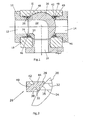
- An outlet channel 12, an outlet channel 14 and a are in a housing 18 Inlet channel 16 provided.
- the inlet channel 16 is via an intermediate part or a sleeve 10 connected to the housing 18.
- an essentially spherical switching element 20 is arranged.
- In the in Fig. 1 shows a medium flowing through the inlet channel 16 a channel 22 of the switching element 20 into the outlet channel 12.
- annular sealing elements 24 and 26 are provided for sealing the outlet channels 12, 14 against the switching element 20.
- the sealing elements 24, 26 that are preferably made of an elastomeric plastic, have two annular sealing lips 28,30 (Fig. 2), each along a circular line 32nd or 34 abut the spherical switching element 20.
- two in Sealing lips 28, 30 running essentially parallel to one another is one Double seal realized. This ensures a low leakage.
- annular recess 36 Between the two sealing lips 28, 30 there is an annular recess 36 provided that is concave in the illustrated embodiment. This increases the elasticity and mobility of the sealing lips 28, 30. Furthermore, the sealing lips 28, 30 can occur when increased forces occur be pushed apart and achieve a higher sealing effect. The Both sealing lips 28, 30 point to the spherical switching element 20 such an angle that the two sealing lips 28,30 when increasing the pressing force are pushed apart.
- the outlet channel 14 is closed, see above that an increased pressure is applied to part of the sealing element 26 and 24. This leads to the fact that the inner sealing lip 30 is pressed against the switching element becomes.
- the sealing lip 30 has a to increase the tightness Pressure surface 38, which points in the direction of the inlet channel 16.
- the sealing element 24, 26 has a foot part 40, a web part 42 and a head part 44.
- the web part 42, the opposite Foot part 40 and compared to the head part 44 a significantly smaller Cross section has an elastic design. This can be a good one Power transmission and thus a bias of the sealing lips 28,30 achieved become.
- the design of the sealing element 24, 26 by an annular causes foot part 40, an annular head part 44 and an annular web 42, that the sealing element 24, 26 acts as a soft spring. Because of this relatively light but tight pressure of the sealing lips 28,30 on the switching element 20 is one low frictional force related to the axis of rotation and thus a low one Torque required to adjust the switching element 20.
- stop element or stop ring 48 or 50 intended. Through the stop ring 48.50, which is also within the Housing 18 is arranged, the maximum displacement of the Switching element 20 limited in the axial direction.
- clamping ring 46 together with the Sealing element 24 or 26 and / or together with the stop element 50 train in one piece.
- the assembly of the sealing elements 24, 26, the clamping rings 46 and the Stop element 48.50 takes place before screwing in the sleeve 10 or one opposite sleeve.
Landscapes
- Engineering & Computer Science (AREA)
- General Engineering & Computer Science (AREA)
- Mechanical Engineering (AREA)
- Taps Or Cocks (AREA)
Abstract
Description
- Fig. 1
- eine schematische Schnittansicht eines erfindungsgemäßen Kugelventils und
- Fig. 2
- eine schematische Vergrößerung des Bereichs II in Fig. 1.
Claims (7)
- Kugelventil für Brennstoffaggregate, mit
mindestens einem Auslasskanal (12,14),
mindestens einem Einlasskanal (16),
einem zwischen dem Einlasskanal (16) und dem Auslasskanal (12,14) angeordneten im Wesentlichen kugelförmigen Schaltelement (20), wobei durch Betätigen des Schaltelements (20) der Einlasskanal (16) mit dem Auslasskanal (12,14) verbunden oder eine Verbindung unterbrochen werden kann, und
einem an dem Schaltelement (20) anliegenden Dichtelement (24,26),
dadurch gekennzeichnet, dass
das Dichtelement (24,26) zwei Dichtlippen (28,30) aufweist, die jeweils entlang einer Kreislinie (32,34) das Schaltelement (20) berühren. - Kugelventil nach Anspruch 1, dadurch gekennzeichnet, dass zwischen den beiden Dichtlippen (28,30) eine ringförmige Ausnehmung (36) vorgesehen ist, die in Richtung des Schaltelements (20) offen ist.
- Kugelventil nach Anspruch 1 oder 2, dadurch gekennzeichnet, dass zumindest eine Dichtlippe (30) eine Andrückfläche (38) aufweist, so dass bei anstehendem Druck die Dichtwirkung verbessert wird.
- Kugelventil nach einem der Ansprüche 1-3, dadurch gekennzeichnet, dass das Dichtelement (24,26) ein Fußteil (40) zur Anordnung in einem Gehäuse (18), ein die Dichtlippen (28,30) aufweisendes Kopfteil (44) und ein das Fußteil (40) mit dem Kopfteil (44) verbindendes elastisches Stegteil (42) aufweist.
- Kugelventil nach einem der Ansprüche 1-4, gekennzeichnet durch ein Anschlagelement (48,50) zur Begrenzung der axialen Verschiebbarkeit des Schaltelements (20).
- Kugelventil nach einem der Ansprüche 1-5, gekennzeichnet durch einen Klemmring (56) zur Lagefixierung des Dichtelementes (24,26) in dem Gehäuse (18).
- Kugelventil nach einem der Ansprüche 1-6, dadurch gekennzeichnet, dass der Klemmring (46) und/oder das Dichtelement (26) und/oder das Anschlagelement (28,50) einstückig ausgebildet sind.
Applications Claiming Priority (2)
| Application Number | Priority Date | Filing Date | Title |
|---|---|---|---|
| DE10238478 | 2002-08-22 | ||
| DE10238478A DE10238478A1 (de) | 2002-08-22 | 2002-08-22 | Kugelventil |
Publications (2)
| Publication Number | Publication Date |
|---|---|
| EP1391644A1 true EP1391644A1 (de) | 2004-02-25 |
| EP1391644B1 EP1391644B1 (de) | 2005-10-19 |
Family
ID=30775509
Family Applications (1)
| Application Number | Title | Priority Date | Filing Date |
|---|---|---|---|
| EP03018520A Expired - Lifetime EP1391644B1 (de) | 2002-08-22 | 2003-08-16 | Kugelventil |
Country Status (4)
| Country | Link |
|---|---|
| US (1) | US20040036052A1 (de) |
| EP (1) | EP1391644B1 (de) |
| DE (2) | DE10238478A1 (de) |
| ES (1) | ES2247463T3 (de) |
Cited By (4)
| Publication number | Priority date | Publication date | Assignee | Title |
|---|---|---|---|---|
| RU2467231C1 (ru) * | 2011-07-26 | 2012-11-20 | Федеральное Государственное Унитарное Предприятие "Государственный научно-производственный ракетно-космический центр "ЦСКБ-Прогресс" (ФГУП "ГНПРКЦ "ЦСКБ-Прогресс") | Уплотнительное соединение с упругой кромкой |
| EP2545309A1 (de) * | 2010-03-08 | 2013-01-16 | Indufil B.V. | Kugelventil |
| WO2020018340A1 (en) * | 2018-07-17 | 2020-01-23 | Illinois Tool Works Inc. | Coolant valve for a vehicle |
| NL2033931B1 (en) * | 2023-01-10 | 2024-07-18 | Dmn Machf Noordwykerhout B V | Diverter valve |
Families Citing this family (11)
| Publication number | Priority date | Publication date | Assignee | Title |
|---|---|---|---|---|
| EP2360402B1 (de) | 2007-05-24 | 2012-10-03 | Michael Tappe | Kunststoff-Ventilkugel |
| DE102007024625A1 (de) * | 2007-05-24 | 2008-11-27 | Michael Tappe | Kugelventil aus Kunststoff |
| US8413684B2 (en) * | 2009-09-16 | 2013-04-09 | Schneider Electric Buildings, Llc | Ball valve with anti-rotational pressure plate |
| IT1398767B1 (it) * | 2010-03-03 | 2013-03-18 | Tyco Valves & Controls Italia S R L | Seggio metallico di valvole di intercettazione fluido |
| JP6422236B2 (ja) * | 2014-05-15 | 2018-11-14 | 株式会社山田製作所 | 電動ウォータバルブ |
| DE102015001122A1 (de) * | 2015-01-29 | 2016-08-04 | Daimler Ag | Primäres Dichtungssystem |
| EP3242061B1 (de) * | 2016-05-04 | 2019-03-06 | Hyundai Motor Company | Kühlmittelregelventileinheit mit dichtungsstruktur |
| US10794488B2 (en) * | 2016-10-04 | 2020-10-06 | Nok Corporation | Sealing device and sealing assembly |
| CN107420559B (zh) * | 2017-08-02 | 2024-04-02 | 上海鸿研物流技术有限公司 | 阀门 |
| EP3940275B1 (de) * | 2020-07-17 | 2024-09-04 | Goodrich Corporation | Ventilanordnung |
| EP4102115B1 (de) * | 2021-06-11 | 2024-11-13 | Illinois Tool Works Inc. | Dichtung und ventilvorrichtung mit einer solchen dichtung, sowie verfahren zum abdichten einer ventilvorrichtung |
Citations (4)
| Publication number | Priority date | Publication date | Assignee | Title |
|---|---|---|---|---|
| US3345032A (en) * | 1964-11-10 | 1967-10-03 | Jamesbury Corp | Three-way ball valve |
| US3656711A (en) * | 1970-08-17 | 1972-04-18 | Encon Mfg Co | Thermoset plastic ball valve |
| US4236691A (en) * | 1978-11-29 | 1980-12-02 | Jamesbury Corporation | Ball valve to relieve cavity pressure |
| US4940208A (en) * | 1989-01-10 | 1990-07-10 | Kemp Development Corporation | Ball valve |
Family Cites Families (5)
| Publication number | Priority date | Publication date | Assignee | Title |
|---|---|---|---|---|
| US3584641A (en) * | 1968-01-03 | 1971-06-15 | Rockwell Mfg Co | Lubricated valve assembly |
| JPS59110964A (ja) * | 1982-12-16 | 1984-06-27 | Sekisui Chem Co Ltd | ボ−ルバルブ及びその製造方法 |
| US5052657A (en) * | 1990-11-02 | 1991-10-01 | Shaw Industries, Ltd. | Ball valve |
| DE29518724U1 (de) * | 1995-11-25 | 1997-03-27 | Pfeiffer Chemie-Armaturenbau GmbH, 47906 Kempen | Kugelhahn |
| DE29806226U1 (de) * | 1998-04-04 | 1998-06-18 | Xomox International GmbH & Co, 88131 Lindau | Armatur |
-
2002
- 2002-08-22 DE DE10238478A patent/DE10238478A1/de not_active Withdrawn
-
2003
- 2003-08-16 ES ES03018520T patent/ES2247463T3/es not_active Expired - Lifetime
- 2003-08-16 DE DE50301400T patent/DE50301400D1/de not_active Expired - Lifetime
- 2003-08-16 EP EP03018520A patent/EP1391644B1/de not_active Expired - Lifetime
- 2003-08-20 US US10/644,271 patent/US20040036052A1/en not_active Abandoned
Patent Citations (4)
| Publication number | Priority date | Publication date | Assignee | Title |
|---|---|---|---|---|
| US3345032A (en) * | 1964-11-10 | 1967-10-03 | Jamesbury Corp | Three-way ball valve |
| US3656711A (en) * | 1970-08-17 | 1972-04-18 | Encon Mfg Co | Thermoset plastic ball valve |
| US4236691A (en) * | 1978-11-29 | 1980-12-02 | Jamesbury Corporation | Ball valve to relieve cavity pressure |
| US4940208A (en) * | 1989-01-10 | 1990-07-10 | Kemp Development Corporation | Ball valve |
Cited By (5)
| Publication number | Priority date | Publication date | Assignee | Title |
|---|---|---|---|---|
| EP2545309A1 (de) * | 2010-03-08 | 2013-01-16 | Indufil B.V. | Kugelventil |
| RU2467231C1 (ru) * | 2011-07-26 | 2012-11-20 | Федеральное Государственное Унитарное Предприятие "Государственный научно-производственный ракетно-космический центр "ЦСКБ-Прогресс" (ФГУП "ГНПРКЦ "ЦСКБ-Прогресс") | Уплотнительное соединение с упругой кромкой |
| WO2020018340A1 (en) * | 2018-07-17 | 2020-01-23 | Illinois Tool Works Inc. | Coolant valve for a vehicle |
| US11525519B2 (en) | 2018-07-17 | 2022-12-13 | Illinois Tool Works Inc. | Coolant valve for a vehicle |
| NL2033931B1 (en) * | 2023-01-10 | 2024-07-18 | Dmn Machf Noordwykerhout B V | Diverter valve |
Also Published As
| Publication number | Publication date |
|---|---|
| EP1391644B1 (de) | 2005-10-19 |
| DE10238478A1 (de) | 2004-03-04 |
| ES2247463T3 (es) | 2006-03-01 |
| US20040036052A1 (en) | 2004-02-26 |
| DE50301400D1 (de) | 2005-11-24 |
Similar Documents
| Publication | Publication Date | Title |
|---|---|---|
| EP1391644B1 (de) | Kugelventil | |
| EP1563209B1 (de) | Sekundärdichtungselement | |
| DE2529509C2 (de) | ||
| DE102010001345B4 (de) | Drehdurchführung | |
| DE60023733T2 (de) | Kugelventilsitzdichtung | |
| EP1335158B1 (de) | Klappenventil für Brennstoffaggregate | |
| DE10259608A1 (de) | Füllventil für eine Klimaanlage | |
| DE1750547A1 (de) | Absperrhahn | |
| DE4025832A1 (de) | Absperr- und regelklappe | |
| DE2444716C3 (de) | Absperrhahn, insbesondere Kugelhahn, mit schwimmend gelagertem Küken | |
| EP0906528B1 (de) | Dichtungsanordnung | |
| DE102009022334B4 (de) | Dichtung mit L-förmigem Querschnitt | |
| DE10325196B3 (de) | Bypassventil | |
| EP4056880A1 (de) | Drehkolbenabdichtung | |
| DE1550499B1 (de) | Drosselklappe mit nachstellbarer sitzdichtung | |
| DE10329024A1 (de) | Dichtung für einen Drehschieber eines Kühlmittelthermostaten | |
| DE102018123724A1 (de) | Dichtungssystem für ein Ventil | |
| DE10328246B4 (de) | Kraftfahrzeugventil | |
| DE10140054A1 (de) | Absperrarmatur mit einem drehbeweglichen Drossel-und Verschlußkörper | |
| DE102021212267A1 (de) | Drosselklappenanordnung und Brennstoffzellensystem | |
| EP1182386B1 (de) | Absperrvorrichtung mit Dichtung | |
| EP0110336B1 (de) | Mischventil | |
| DE3219309A1 (de) | Ventil mit einem ventilverschluss | |
| DE102023204506A1 (de) | Fluidventil sowie Ventilgehäuse und Ventileinsatz für ein Fluidventil | |
| DE102024121043A1 (de) | Ventil, insbesondere expansionsventil oder abschaltventil |
Legal Events
| Date | Code | Title | Description |
|---|---|---|---|
| PUAI | Public reference made under article 153(3) epc to a published international application that has entered the european phase |
Free format text: ORIGINAL CODE: 0009012 |
|
| AK | Designated contracting states |
Kind code of ref document: A1 Designated state(s): AT BE BG CH CY CZ DE DK EE ES FI FR GB GR HU IE IT LI LU MC NL PT RO SE SI SK TR |
|
| AX | Request for extension of the european patent |
Extension state: AL LT LV MK |
|
| 17P | Request for examination filed |
Effective date: 20040811 |
|
| 17Q | First examination report despatched |
Effective date: 20040924 |
|
| AKX | Designation fees paid |
Designated state(s): DE ES FR GB IT |
|
| GRAP | Despatch of communication of intention to grant a patent |
Free format text: ORIGINAL CODE: EPIDOSNIGR1 |
|
| GRAS | Grant fee paid |
Free format text: ORIGINAL CODE: EPIDOSNIGR3 |
|
| GRAA | (expected) grant |
Free format text: ORIGINAL CODE: 0009210 |
|
| AK | Designated contracting states |
Kind code of ref document: B1 Designated state(s): DE ES FR GB IT |
|
| REG | Reference to a national code |
Ref country code: GB Ref legal event code: FG4D Free format text: NOT ENGLISH |
|
| REF | Corresponds to: |
Ref document number: 50301400 Country of ref document: DE Date of ref document: 20051124 Kind code of ref document: P |
|
| GBT | Gb: translation of ep patent filed (gb section 77(6)(a)/1977) |
Effective date: 20051108 |
|
| REG | Reference to a national code |
Ref country code: ES Ref legal event code: FG2A Ref document number: 2247463 Country of ref document: ES Kind code of ref document: T3 |
|
| ET | Fr: translation filed | ||
| PLBE | No opposition filed within time limit |
Free format text: ORIGINAL CODE: 0009261 |
|
| STAA | Information on the status of an ep patent application or granted ep patent |
Free format text: STATUS: NO OPPOSITION FILED WITHIN TIME LIMIT |
|
| 26N | No opposition filed |
Effective date: 20060720 |
|
| PGFP | Annual fee paid to national office [announced via postgrant information from national office to epo] |
Ref country code: ES Payment date: 20090821 Year of fee payment: 7 Ref country code: FR Payment date: 20090819 Year of fee payment: 7 |
|
| PGFP | Annual fee paid to national office [announced via postgrant information from national office to epo] |
Ref country code: GB Payment date: 20090821 Year of fee payment: 7 |
|
| PGFP | Annual fee paid to national office [announced via postgrant information from national office to epo] |
Ref country code: DE Payment date: 20091026 Year of fee payment: 7 |
|
| PGFP | Annual fee paid to national office [announced via postgrant information from national office to epo] |
Ref country code: IT Payment date: 20090824 Year of fee payment: 7 |
|
| GBPC | Gb: european patent ceased through non-payment of renewal fee |
Effective date: 20100816 |
|
| REG | Reference to a national code |
Ref country code: FR Ref legal event code: ST Effective date: 20110502 |
|
| PG25 | Lapsed in a contracting state [announced via postgrant information from national office to epo] |
Ref country code: IT Free format text: LAPSE BECAUSE OF NON-PAYMENT OF DUE FEES Effective date: 20100816 |
|
| REG | Reference to a national code |
Ref country code: DE Ref legal event code: R119 Ref document number: 50301400 Country of ref document: DE Effective date: 20110301 |
|
| PG25 | Lapsed in a contracting state [announced via postgrant information from national office to epo] |
Ref country code: FR Free format text: LAPSE BECAUSE OF NON-PAYMENT OF DUE FEES Effective date: 20100831 Ref country code: DE Free format text: LAPSE BECAUSE OF NON-PAYMENT OF DUE FEES Effective date: 20110301 |
|
| PG25 | Lapsed in a contracting state [announced via postgrant information from national office to epo] |
Ref country code: GB Free format text: LAPSE BECAUSE OF NON-PAYMENT OF DUE FEES Effective date: 20100816 |
|
| REG | Reference to a national code |
Ref country code: ES Ref legal event code: FD2A Effective date: 20111019 |
|
| PG25 | Lapsed in a contracting state [announced via postgrant information from national office to epo] |
Ref country code: ES Free format text: LAPSE BECAUSE OF NON-PAYMENT OF DUE FEES Effective date: 20100817 |