EP1391583A1 - Heissgas führendes Gassammelrohr mit Luftkühlung - Google Patents
Heissgas führendes Gassammelrohr mit Luftkühlung Download PDFInfo
- Publication number
- EP1391583A1 EP1391583A1 EP03015750A EP03015750A EP1391583A1 EP 1391583 A1 EP1391583 A1 EP 1391583A1 EP 03015750 A EP03015750 A EP 03015750A EP 03015750 A EP03015750 A EP 03015750A EP 1391583 A1 EP1391583 A1 EP 1391583A1
- Authority
- EP
- European Patent Office
- Prior art keywords
- gas
- cooling air
- ribs
- ring channel
- flow channel
- Prior art date
- Legal status (The legal status is an assumption and is not a legal conclusion. Google has not performed a legal analysis and makes no representation as to the accuracy of the status listed.)
- Granted
Links
Images


Classifications
-
- F—MECHANICAL ENGINEERING; LIGHTING; HEATING; WEAPONS; BLASTING
- F01—MACHINES OR ENGINES IN GENERAL; ENGINE PLANTS IN GENERAL; STEAM ENGINES
- F01D—NON-POSITIVE DISPLACEMENT MACHINES OR ENGINES, e.g. STEAM TURBINES
- F01D25/00—Component parts, details, or accessories, not provided for in, or of interest apart from, other groups
- F01D25/08—Cooling; Heating; Heat-insulation
- F01D25/12—Cooling
-
- F—MECHANICAL ENGINEERING; LIGHTING; HEATING; WEAPONS; BLASTING
- F01—MACHINES OR ENGINES IN GENERAL; ENGINE PLANTS IN GENERAL; STEAM ENGINES
- F01D—NON-POSITIVE DISPLACEMENT MACHINES OR ENGINES, e.g. STEAM TURBINES
- F01D9/00—Stators
- F01D9/02—Nozzles; Nozzle boxes; Stator blades; Guide conduits, e.g. individual nozzles
- F01D9/023—Transition ducts between combustor cans and first stage of the turbine in gas-turbine engines; their cooling or sealings
-
- F—MECHANICAL ENGINEERING; LIGHTING; HEATING; WEAPONS; BLASTING
- F05—INDEXING SCHEMES RELATING TO ENGINES OR PUMPS IN VARIOUS SUBCLASSES OF CLASSES F01-F04
- F05D—INDEXING SCHEME FOR ASPECTS RELATING TO NON-POSITIVE-DISPLACEMENT MACHINES OR ENGINES, GAS-TURBINES OR JET-PROPULSION PLANTS
- F05D2260/00—Function
- F05D2260/20—Heat transfer, e.g. cooling
- F05D2260/201—Heat transfer, e.g. cooling by impingement of a fluid
-
- F—MECHANICAL ENGINEERING; LIGHTING; HEATING; WEAPONS; BLASTING
- F05—INDEXING SCHEMES RELATING TO ENGINES OR PUMPS IN VARIOUS SUBCLASSES OF CLASSES F01-F04
- F05D—INDEXING SCHEME FOR ASPECTS RELATING TO NON-POSITIVE-DISPLACEMENT MACHINES OR ENGINES, GAS-TURBINES OR JET-PROPULSION PLANTS
- F05D2260/00—Function
- F05D2260/20—Heat transfer, e.g. cooling
- F05D2260/221—Improvement of heat transfer
- F05D2260/2214—Improvement of heat transfer by increasing the heat transfer surface
- F05D2260/22141—Improvement of heat transfer by increasing the heat transfer surface using fins or ribs
-
- F—MECHANICAL ENGINEERING; LIGHTING; HEATING; WEAPONS; BLASTING
- F05—INDEXING SCHEMES RELATING TO ENGINES OR PUMPS IN VARIOUS SUBCLASSES OF CLASSES F01-F04
- F05D—INDEXING SCHEME FOR ASPECTS RELATING TO NON-POSITIVE-DISPLACEMENT MACHINES OR ENGINES, GAS-TURBINES OR JET-PROPULSION PLANTS
- F05D2260/00—Function
- F05D2260/94—Functionality given by mechanical stress related aspects such as low cycle fatigue [LCF] of high cycle fatigue [HCF]
-
- F—MECHANICAL ENGINEERING; LIGHTING; HEATING; WEAPONS; BLASTING
- F05—INDEXING SCHEMES RELATING TO ENGINES OR PUMPS IN VARIOUS SUBCLASSES OF CLASSES F01-F04
- F05D—INDEXING SCHEME FOR ASPECTS RELATING TO NON-POSITIVE-DISPLACEMENT MACHINES OR ENGINES, GAS-TURBINES OR JET-PROPULSION PLANTS
- F05D2260/00—Function
- F05D2260/94—Functionality given by mechanical stress related aspects such as low cycle fatigue [LCF] of high cycle fatigue [HCF]
- F05D2260/941—Functionality given by mechanical stress related aspects such as low cycle fatigue [LCF] of high cycle fatigue [HCF] particularly aimed at mechanical or thermal stress reduction
Definitions
- the invention relates to a hot gas leading gas collector with the features of the preamble of claim 1.
- a generic, two-armed, also called downpipe Gas collecting tube is known from DE 198 15 473 A1. Due to the special form of the inlet connection of this gas collection tube in the outlet cross section formed by the gas ring channel the middle areas much more thermally stressed than the upper and the lower area.
- the gas ring channel of the gas collecting tube is cooled insofar that Cooling air is guided outside of the gas ring channel along. These Cooling air is taken from the compressor of the gas turbine plant. At the edges of the gas ring channel are provided two annular flanges, with slots for the passage of cooling air into the Flow channel of the gas turbine are provided. At one of the DE 100 32 454 A1 known gas collection tube are the cross sections the slots over the circumference of the annular flange so unevenly distributed, that at the more thermally loaded Areas of the gas collection tube a larger amount of cooling air is passed along as less thermally strong burdened areas. This is caused by an uneven Cooling air quantity uniform cooling of the gas ring channel of Gas collection tube reached.
- the invention is based on the object, the generic To design gas collection tube such that the DE 100 32 454 A1 known leadership of the cooling air by other means simultaneous intensification of the cooling is achieved.
- the ribs are so misplaced that they are directed to the gas collection pipe Redirect cooling air flow and preferably to the middle, at strongest thermally loaded area of the gas collection pipe judge.
- the surface of the more thermally stressed area increases, where by a better heat dissipation is achieved.
- Benefits consist in a reduction of the local, life-limiting material temperature, in one Equalization of the temperature distribution, in a reduction of temperature stresses, in an improvement of the temperature and Corrosion resistance and in an increase of Life of the gas collection tube.
- Another advantage is that no increased Cooling air required.
- the hot zones are supplied with additional cooling air. This additional Cooling air is usually not available, or they leads to a reduction in the efficiency of the machine.
- a gas turbine plant is shown in this regard, as it is necessary for the understanding of the invention.
- the Gas turbine plant is known per se and consists of a Compressor, a gas turbine and in the present case of two external combustion chambers 9 in V arrangement. In the presentation 4, only one of the combustion chambers 9 can be seen.
- the Gas turbine includes a turbine runner 10, the rotor blades 12 carries, which is within the annular flow channel 13th the gas turbine are located. At the flow channel 13 closes a serving as a gas collecting gas ring channel 4 at.
- the Compressor of the gas turbine plant is in Fig. 4, only the Recognize compressor blade 11 of the compressor rotor.
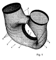
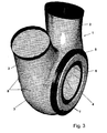
- the connection between the two combustion chambers 9 of Gas turbine plant and the flow channel 13 of the gas turbine takes place via a hot gas leading two-arm gas manifold 1, which is shown in more detail in Figs. 1 to 3.
- the gas collection pipe 1 is provided with two inlet ports 2, each to the Gas outlet of one of the combustion chambers 9 are connected.
- the Inlet 2 open through a bend 3 of 90 ° in one serving as a gas collecting gas ring channel 4 in the lower part of the Gas collecting pipe 1 a.
- the gas collecting pipe 1 is provided with an outer Ring flange 5 and an inner annular flange 6 is provided, the corresponding mating flanges of the housing of the gas turbine be connected.
- the compressed hot gas flows out of the Combustion chambers 9 through the inlet 2 of the gas collection pipe. 1 and is brought together and collected in the gas ring channel 4, before flowing into the flow channel 13 and the turbine runner 10 offset with the blades 12 in rotation.
- the Gasringkanal 4 of the gas collection tube 1 by the zoomed Hot gas unevenly thermally loaded Due to the formation of the entrance 2 is the Gasringkanal 4 of the gas collection tube 1 by the zoomed Hot gas unevenly thermally loaded.
- the middle areas, the 3 o'clock and the 9 o'clock position correspond, more heavily loaded than the upper and the lower Area of the gas ring channel 4 corresponding to the 6 o'clock and the 12 o'clock position.
- the entire gas collection pipe 1 is outside by compressor air convectively cooled, the compressor of the gas turbine plant is removed.
- This cooling air is outside of the bend 3 and then guided along the gas ring channel 4 along.
- To this Purpose are in the outer and inner annular flange 5, 6, the as rings protrude into the flow path of the cooling air, slots 7 or other openings attached. Through these slots 7 the cooling air flows off.
- Driving force for the flow of Cooling air is a pressure difference that extends to both sides of the slotted annular flanges 5, 6 builds.
- the ribs 8 extend in the radial direction over the near-wall area.
- the height of the ribs 8 depends on the size of the Gas turbine off. At a height of the gas ring channel 4 of about 70 mm, the height of the ribs 8 is about 5 to 10 mm.
Landscapes
- Engineering & Computer Science (AREA)
- Mechanical Engineering (AREA)
- General Engineering & Computer Science (AREA)
- Turbine Rotor Nozzle Sealing (AREA)
- Heat-Exchange Devices With Radiators And Conduit Assemblies (AREA)
- Sampling And Sample Adjustment (AREA)
Abstract
Description
- Fig. 1
- in perspektivischer Ansicht ein Gassammelrohr nach der Erfindung schräg von oben von der Anströmseite her gesehen,
- Fig. 2
- in perspektivischer Ansicht ein Gassammelrohr nach der Erfindung von der Anströmseite her gesehen,
- Fig. 3
- in perspektivischer Ansicht ein Gassammelrohr nach der Erfindung schräg von der Seite aus gesehen und
- Fig. 4
- einen Ausschnitt aus einer Gasturbinenanlage als Halbschnitt durch den Übergang zwischen dem Verdichterteil und dem Turbinenteil der Gasturbinenanlage.
Claims (3)
- Heißgas führendes Gassammelrohr zur Verbindung zwischen den Brennkammern (9) einer Gasturbinenanlage und dem Strömungskanal (13) der Gasturbine, wobei das Gassammelrohr (1) zwei Eintrittsstutzen (2) aufweist, die über eine Krümmung (3) axial in einen Gasringkanal (4) einmünden, der an den Strömungskanal (13) angeschlossen ist und wobei Kühlluft außen an der Krümmung (3) entlang geführt ist, dadurch gekennzeichnet, dass auf der dem Strömungskanal (13) abgewandten Seite außen auf dem Gassammelrohr (1) im Bereich der Krümmung (3) mehrere Rippen (8) mit Abstand voneinander angebracht sind.
- Gassammelrohr nach Anspruch 1, dadurch gekennzeichnet, dass die Rippen (8) entlang der Krümmung (3) ausgehend von dem Übergangsbereich in die Eintrittsstutzen (2) bis in den mittleren Bereich des Gasringkanales (4) auf dessen Innenund Außenseite geführt sind.
- Gassammelrohr nach Anspruch 1 oder 2, dadurch gekennzeichnet, dass die Höhe der Rippen (8) etwa 10 % der Höhe des Gasringkanales (4) beträgt.
Applications Claiming Priority (2)
| Application Number | Priority Date | Filing Date | Title |
|---|---|---|---|
| DE10239534A DE10239534A1 (de) | 2002-08-23 | 2002-08-23 | Heißgas führendes Gassammelrohr |
| DE10239534 | 2002-08-23 |
Publications (2)
| Publication Number | Publication Date |
|---|---|
| EP1391583A1 true EP1391583A1 (de) | 2004-02-25 |
| EP1391583B1 EP1391583B1 (de) | 2008-03-05 |
Family
ID=30775573
Family Applications (1)
| Application Number | Title | Priority Date | Filing Date |
|---|---|---|---|
| EP03015750A Expired - Lifetime EP1391583B1 (de) | 2002-08-23 | 2003-07-10 | Heissgas führendes Gassammelrohr mit Luftkühlung |
Country Status (7)
| Country | Link |
|---|---|
| US (1) | US6996992B2 (de) |
| EP (1) | EP1391583B1 (de) |
| JP (1) | JP2007046456A (de) |
| CN (1) | CN1255623C (de) |
| AT (1) | ATE388303T1 (de) |
| CA (1) | CA2424166C (de) |
| DE (2) | DE10239534A1 (de) |
Cited By (1)
| Publication number | Priority date | Publication date | Assignee | Title |
|---|---|---|---|---|
| EP2157286A1 (de) * | 2008-08-21 | 2010-02-24 | Siemens Aktiengesellschaft | Gasturbine mit angewinkeltem Mischgehäuse und Verfahren zur Turbinenanströmung |
Families Citing this family (3)
| Publication number | Priority date | Publication date | Assignee | Title |
|---|---|---|---|---|
| EP2157285A1 (de) * | 2008-08-21 | 2010-02-24 | Siemens Aktiengesellschaft | Gasturbineanordnung und Verfahren zur Turbinenanströmung |
| USD818502S1 (en) * | 2015-12-17 | 2018-05-22 | General Electric Company | Turbocharger transition section |
| USD814522S1 (en) * | 2016-06-21 | 2018-04-03 | General Electric Company | Transition section for a turbocharged engine |
Citations (7)
| Publication number | Priority date | Publication date | Assignee | Title |
|---|---|---|---|---|
| GB624285A (en) * | 1946-07-01 | 1949-06-01 | Westinghouse Electric Int Co | Improvements in or relating to combustion apparatus |
| CH599458A5 (en) * | 1976-12-24 | 1978-05-31 | Sim Sa Ets | Air cooled internal combustion engine |
| EP0123101A2 (de) * | 1983-04-22 | 1984-10-31 | KHD Canada Inc. DEUTZ R & D Devision | Zylinderkopf für eine luftgekühlte Hubkolbenbrennkraftmaschine |
| JPH1026022A (ja) * | 1996-07-10 | 1998-01-27 | Yanmar Diesel Engine Co Ltd | 空冷式内燃機関の排気系構造 |
| GB2361302A (en) * | 2000-04-13 | 2001-10-17 | Rolls Royce Plc | Discharge nozzle for a gas turbine engine combustion chamber |
| DE10032454A1 (de) * | 2000-07-04 | 2002-01-17 | Man Turbomasch Ag Ghh Borsig | Vorrichtung zum Kühlen eines ungleichmäßig stark temperaturbelasteten Bauteiles |
| US20020078691A1 (en) * | 2000-12-22 | 2002-06-27 | Rainer Hoecker | Arrangement for cooling a component |
Family Cites Families (15)
| Publication number | Priority date | Publication date | Assignee | Title |
|---|---|---|---|---|
| US2526281A (en) * | 1947-04-10 | 1950-10-17 | Wright Aeronautical Corp | Turbine and turbine nozzle construction |
| CH633347A5 (de) * | 1978-08-03 | 1982-11-30 | Bbc Brown Boveri & Cie | Gasturbine. |
| JPS62131927A (ja) * | 1985-12-04 | 1987-06-15 | Hitachi Ltd | ガスタ−ビン燃焼器尾筒の冷却構造 |
| GB2261281B (en) | 1991-11-08 | 1995-01-18 | Bmw Rolls Royce Gmbh | A combustion-chamber casting for a gas turbine |
| US5274991A (en) * | 1992-03-30 | 1994-01-04 | General Electric Company | Dry low NOx multi-nozzle combustion liner cap assembly |
| DE4242721A1 (de) * | 1992-12-17 | 1994-06-23 | Asea Brown Boveri | Gasturbinenbrennkammer |
| EP0718468B1 (de) * | 1994-12-20 | 2001-10-31 | General Electric Company | Verstärkungrahmen für Gasturbinenbrennkammerendstück |
| US6018950A (en) * | 1997-06-13 | 2000-02-01 | Siemens Westinghouse Power Corporation | Combustion turbine modular cooling panel |
| GB2328011A (en) * | 1997-08-05 | 1999-02-10 | Europ Gas Turbines Ltd | Combustor for gas or liquid fuelled turbine |
| DE19815473A1 (de) * | 1998-04-07 | 1999-10-14 | Ghh Borsig Turbomaschinen Gmbh | Heißgasführendes Gassammelrohr einer Gasturbine |
| JP2895831B1 (ja) * | 1998-04-22 | 1999-05-24 | 川崎重工業株式会社 | スクロールの冷却を改善したガスタービン |
| GB9813972D0 (en) * | 1998-06-30 | 1998-08-26 | Rolls Royce Plc | A combustion chamber |
| US6196793B1 (en) * | 1999-01-11 | 2001-03-06 | General Electric Company | Nozzle box |
| JP3478531B2 (ja) * | 2000-04-21 | 2003-12-15 | 川崎重工業株式会社 | ガスタービンのセラミック部品支持構造 |
| US6675584B1 (en) * | 2002-08-15 | 2004-01-13 | Power Systems Mfg, Llc | Coated seal article used in turbine engines |
-
2002
- 2002-08-23 DE DE10239534A patent/DE10239534A1/de not_active Withdrawn
-
2003
- 2003-03-17 US US10/390,407 patent/US6996992B2/en not_active Expired - Fee Related
- 2003-04-01 CA CA002424166A patent/CA2424166C/en not_active Expired - Fee Related
- 2003-04-24 CN CNB031220525A patent/CN1255623C/zh not_active Expired - Fee Related
- 2003-07-08 JP JP2003193957A patent/JP2007046456A/ja active Pending
- 2003-07-10 DE DE50309297T patent/DE50309297D1/de not_active Expired - Lifetime
- 2003-07-10 EP EP03015750A patent/EP1391583B1/de not_active Expired - Lifetime
- 2003-07-10 AT AT03015750T patent/ATE388303T1/de not_active IP Right Cessation
Patent Citations (7)
| Publication number | Priority date | Publication date | Assignee | Title |
|---|---|---|---|---|
| GB624285A (en) * | 1946-07-01 | 1949-06-01 | Westinghouse Electric Int Co | Improvements in or relating to combustion apparatus |
| CH599458A5 (en) * | 1976-12-24 | 1978-05-31 | Sim Sa Ets | Air cooled internal combustion engine |
| EP0123101A2 (de) * | 1983-04-22 | 1984-10-31 | KHD Canada Inc. DEUTZ R & D Devision | Zylinderkopf für eine luftgekühlte Hubkolbenbrennkraftmaschine |
| JPH1026022A (ja) * | 1996-07-10 | 1998-01-27 | Yanmar Diesel Engine Co Ltd | 空冷式内燃機関の排気系構造 |
| GB2361302A (en) * | 2000-04-13 | 2001-10-17 | Rolls Royce Plc | Discharge nozzle for a gas turbine engine combustion chamber |
| DE10032454A1 (de) * | 2000-07-04 | 2002-01-17 | Man Turbomasch Ag Ghh Borsig | Vorrichtung zum Kühlen eines ungleichmäßig stark temperaturbelasteten Bauteiles |
| US20020078691A1 (en) * | 2000-12-22 | 2002-06-27 | Rainer Hoecker | Arrangement for cooling a component |
Non-Patent Citations (1)
| Title |
|---|
| PATENT ABSTRACTS OF JAPAN vol. 1998, no. 05 30 April 1998 (1998-04-30) * |
Cited By (1)
| Publication number | Priority date | Publication date | Assignee | Title |
|---|---|---|---|---|
| EP2157286A1 (de) * | 2008-08-21 | 2010-02-24 | Siemens Aktiengesellschaft | Gasturbine mit angewinkeltem Mischgehäuse und Verfahren zur Turbinenanströmung |
Also Published As
| Publication number | Publication date |
|---|---|
| ATE388303T1 (de) | 2008-03-15 |
| CN1255623C (zh) | 2006-05-10 |
| EP1391583B1 (de) | 2008-03-05 |
| US20040035116A1 (en) | 2004-02-26 |
| JP2007046456A (ja) | 2007-02-22 |
| CA2424166A1 (en) | 2004-02-23 |
| DE10239534A1 (de) | 2004-04-22 |
| CA2424166C (en) | 2008-09-09 |
| CN1477298A (zh) | 2004-02-25 |
| DE50309297D1 (de) | 2008-04-17 |
| US6996992B2 (en) | 2006-02-14 |
Similar Documents
| Publication | Publication Date | Title |
|---|---|---|
| DE60016937T2 (de) | Antiwirbelsystem für kreiselverdichter | |
| DE60319111T2 (de) | INNEN MONTIERTER RADIALSTROMZWISCHENKüHLER FÜR EINEN VERBRENNUNGSLUFTLADER | |
| EP1985953B1 (de) | Wärmetauscher, insbesondere zur Abgaskühlung, Verfahren zum Betreiben eines solchen Wärmetauschers und System mit einem Abgaskühler | |
| EP1656523B1 (de) | Diffusor für eine gasturbine und gasturbine zur energieerzeugung | |
| DE2354504C2 (de) | Brennkammer für Gasturbinen | |
| DE69018338T2 (de) | Gasturbine. | |
| EP1656497B1 (de) | Diffusor zwischen verdichter und brennkammer einer gasturbine angeordnet | |
| EP2440855B1 (de) | Gliederheizkessel | |
| DE102012015449A1 (de) | Gasturbinenbrennkammer mit Mischluftöffnungen und Luftleitelementen in modularer Bauweise | |
| DE202007005986U1 (de) | Verbrennungsluft- und Abgasanordnung eines Verbrennungsmotors | |
| DE102007023142A1 (de) | Strömungsverdichter für eine Brennkraftmaschine, insbesondere Abgasturbolader mit einem solchen Strömungsverdichter | |
| WO2013045063A2 (de) | Zweistufige aufladevorrichtung | |
| EP1292760B1 (de) | Konfiguration einer kühlbaren turbinenschaufel | |
| EP1789653B1 (de) | Rotor für ein triebwerk | |
| WO2013120560A1 (de) | Turbinenleitschaufel mit einem drosselelement | |
| AT516986B1 (de) | Mehrstufiger abgasturbolader | |
| EP1288435B1 (de) | Turbinenschaufel mit zumindest einer Kühlungsöffnung | |
| EP1391583B1 (de) | Heissgas führendes Gassammelrohr mit Luftkühlung | |
| EP1170464B1 (de) | Vorrichtung zum Kühlen eines ungleichmässig stark temperaturbelasteten Bauteils | |
| EP2196628A1 (de) | Leitschaufelträger | |
| EP1247943A1 (de) | Formstück zur Bildung eines kühlbaren Turbinen-Mantelrings | |
| EP1926963A1 (de) | Wärmetauscher | |
| EP3587748B1 (de) | Gehäusestruktur für eine strömungsmaschine, strömungsmaschine und verfahren zum kühlen eines gehäuseabschnitts einer gehäusestruktur einer strömungsmaschine | |
| DE19963099B4 (de) | Kühlluftbohrungen in Gasturbinenkomponenten | |
| DE2710339C3 (de) | Luftgekühlte Brennkraftmaschine mit einem Axialgebläse |
Legal Events
| Date | Code | Title | Description |
|---|---|---|---|
| PUAI | Public reference made under article 153(3) epc to a published international application that has entered the european phase |
Free format text: ORIGINAL CODE: 0009012 |
|
| AK | Designated contracting states |
Kind code of ref document: A1 Designated state(s): AT BE BG CH CY CZ DE DK EE ES FI FR GB GR HU IE IT LI LU MC NL PT RO SE SI SK TR |
|
| AX | Request for extension of the european patent |
Extension state: AL LT LV MK |
|
| 17P | Request for examination filed |
Effective date: 20040316 |
|
| AKX | Designation fees paid |
Designated state(s): AT BE BG CH CY CZ DE DK EE ES FI FR GB GR HU IE IT LI LU MC NL PT RO SE SI SK TR |
|
| RAP1 | Party data changed (applicant data changed or rights of an application transferred) |
Owner name: MAN TURBO AG |
|
| GRAP | Despatch of communication of intention to grant a patent |
Free format text: ORIGINAL CODE: EPIDOSNIGR1 |
|
| GRAS | Grant fee paid |
Free format text: ORIGINAL CODE: EPIDOSNIGR3 |
|
| GRAA | (expected) grant |
Free format text: ORIGINAL CODE: 0009210 |
|
| AK | Designated contracting states |
Kind code of ref document: B1 Designated state(s): AT BE BG CH CY CZ DE DK EE ES FI FR GB GR HU IE IT LI LU MC NL PT RO SE SI SK TR |
|
| REG | Reference to a national code |
Ref country code: GB Ref legal event code: FG4D Free format text: NOT ENGLISH |
|
| REG | Reference to a national code |
Ref country code: CH Ref legal event code: EP |
|
| REG | Reference to a national code |
Ref country code: IE Ref legal event code: FG4D Free format text: LANGUAGE OF EP DOCUMENT: GERMAN |
|
| REF | Corresponds to: |
Ref document number: 50309297 Country of ref document: DE Date of ref document: 20080417 Kind code of ref document: P |
|
| REG | Reference to a national code |
Ref country code: DE Ref legal event code: R096 Ref document number: 50309297 Country of ref document: DE Effective date: 20080417 |
|
| REG | Reference to a national code |
Ref country code: SE Ref legal event code: TRGR |
|
| PG25 | Lapsed in a contracting state [announced via postgrant information from national office to epo] |
Ref country code: ES Free format text: LAPSE BECAUSE OF FAILURE TO SUBMIT A TRANSLATION OF THE DESCRIPTION OR TO PAY THE FEE WITHIN THE PRESCRIBED TIME-LIMIT Effective date: 20080616 Ref country code: FI Free format text: LAPSE BECAUSE OF FAILURE TO SUBMIT A TRANSLATION OF THE DESCRIPTION OR TO PAY THE FEE WITHIN THE PRESCRIBED TIME-LIMIT Effective date: 20080305 |
|
| PG25 | Lapsed in a contracting state [announced via postgrant information from national office to epo] |
Ref country code: SI Free format text: LAPSE BECAUSE OF FAILURE TO SUBMIT A TRANSLATION OF THE DESCRIPTION OR TO PAY THE FEE WITHIN THE PRESCRIBED TIME-LIMIT Effective date: 20080305 |
|
| REG | Reference to a national code |
Ref country code: IE Ref legal event code: FD4D |
|
| PG25 | Lapsed in a contracting state [announced via postgrant information from national office to epo] |
Ref country code: CZ Free format text: LAPSE BECAUSE OF FAILURE TO SUBMIT A TRANSLATION OF THE DESCRIPTION OR TO PAY THE FEE WITHIN THE PRESCRIBED TIME-LIMIT Effective date: 20080305 Ref country code: SK Free format text: LAPSE BECAUSE OF FAILURE TO SUBMIT A TRANSLATION OF THE DESCRIPTION OR TO PAY THE FEE WITHIN THE PRESCRIBED TIME-LIMIT Effective date: 20080305 Ref country code: PT Free format text: LAPSE BECAUSE OF FAILURE TO SUBMIT A TRANSLATION OF THE DESCRIPTION OR TO PAY THE FEE WITHIN THE PRESCRIBED TIME-LIMIT Effective date: 20080805 |
|
| ET | Fr: translation filed | ||
| PG25 | Lapsed in a contracting state [announced via postgrant information from national office to epo] |
Ref country code: RO Free format text: LAPSE BECAUSE OF FAILURE TO SUBMIT A TRANSLATION OF THE DESCRIPTION OR TO PAY THE FEE WITHIN THE PRESCRIBED TIME-LIMIT Effective date: 20080305 |
|
| PLBE | No opposition filed within time limit |
Free format text: ORIGINAL CODE: 0009261 |
|
| STAA | Information on the status of an ep patent application or granted ep patent |
Free format text: STATUS: NO OPPOSITION FILED WITHIN TIME LIMIT |
|
| PG25 | Lapsed in a contracting state [announced via postgrant information from national office to epo] |
Ref country code: DK Free format text: LAPSE BECAUSE OF FAILURE TO SUBMIT A TRANSLATION OF THE DESCRIPTION OR TO PAY THE FEE WITHIN THE PRESCRIBED TIME-LIMIT Effective date: 20080305 Ref country code: IE Free format text: LAPSE BECAUSE OF FAILURE TO SUBMIT A TRANSLATION OF THE DESCRIPTION OR TO PAY THE FEE WITHIN THE PRESCRIBED TIME-LIMIT Effective date: 20080305 |
|
| 26N | No opposition filed |
Effective date: 20081208 |
|
| REG | Reference to a national code |
Ref country code: DE Ref legal event code: R097 Ref document number: 50309297 Country of ref document: DE Effective date: 20081205 |
|
| PG25 | Lapsed in a contracting state [announced via postgrant information from national office to epo] |
Ref country code: MC Free format text: LAPSE BECAUSE OF NON-PAYMENT OF DUE FEES Effective date: 20080731 |
|
| PG25 | Lapsed in a contracting state [announced via postgrant information from national office to epo] |
Ref country code: EE Free format text: LAPSE BECAUSE OF FAILURE TO SUBMIT A TRANSLATION OF THE DESCRIPTION OR TO PAY THE FEE WITHIN THE PRESCRIBED TIME-LIMIT Effective date: 20080305 Ref country code: BG Free format text: LAPSE BECAUSE OF FAILURE TO SUBMIT A TRANSLATION OF THE DESCRIPTION OR TO PAY THE FEE WITHIN THE PRESCRIBED TIME-LIMIT Effective date: 20080605 |
|
| PG25 | Lapsed in a contracting state [announced via postgrant information from national office to epo] |
Ref country code: CY Free format text: LAPSE BECAUSE OF FAILURE TO SUBMIT A TRANSLATION OF THE DESCRIPTION OR TO PAY THE FEE WITHIN THE PRESCRIBED TIME-LIMIT Effective date: 20080305 |
|
| PG25 | Lapsed in a contracting state [announced via postgrant information from national office to epo] |
Ref country code: AT Free format text: LAPSE BECAUSE OF NON-PAYMENT OF DUE FEES Effective date: 20080710 |
|
| PGFP | Annual fee paid to national office [announced via postgrant information from national office to epo] |
Ref country code: FR Payment date: 20090716 Year of fee payment: 7 |
|
| PGFP | Annual fee paid to national office [announced via postgrant information from national office to epo] |
Ref country code: CH Payment date: 20090715 Year of fee payment: 7 Ref country code: GB Payment date: 20090720 Year of fee payment: 7 Ref country code: NL Payment date: 20090730 Year of fee payment: 7 Ref country code: SE Payment date: 20090715 Year of fee payment: 7 |
|
| PGFP | Annual fee paid to national office [announced via postgrant information from national office to epo] |
Ref country code: BE Payment date: 20090818 Year of fee payment: 7 |
|
| PGFP | Annual fee paid to national office [announced via postgrant information from national office to epo] |
Ref country code: IT Payment date: 20090725 Year of fee payment: 7 |
|
| PG25 | Lapsed in a contracting state [announced via postgrant information from national office to epo] |
Ref country code: HU Free format text: LAPSE BECAUSE OF FAILURE TO SUBMIT A TRANSLATION OF THE DESCRIPTION OR TO PAY THE FEE WITHIN THE PRESCRIBED TIME-LIMIT Effective date: 20080906 Ref country code: LU Free format text: LAPSE BECAUSE OF NON-PAYMENT OF DUE FEES Effective date: 20080710 |
|
| PG25 | Lapsed in a contracting state [announced via postgrant information from national office to epo] |
Ref country code: TR Free format text: LAPSE BECAUSE OF FAILURE TO SUBMIT A TRANSLATION OF THE DESCRIPTION OR TO PAY THE FEE WITHIN THE PRESCRIBED TIME-LIMIT Effective date: 20080305 |
|
| PG25 | Lapsed in a contracting state [announced via postgrant information from national office to epo] |
Ref country code: GR Free format text: LAPSE BECAUSE OF FAILURE TO SUBMIT A TRANSLATION OF THE DESCRIPTION OR TO PAY THE FEE WITHIN THE PRESCRIBED TIME-LIMIT Effective date: 20080606 |
|
| BERE | Be: lapsed |
Owner name: MAN TURBO A.G. Effective date: 20100731 |
|
| REG | Reference to a national code |
Ref country code: NL Ref legal event code: V1 Effective date: 20110201 |
|
| REG | Reference to a national code |
Ref country code: CH Ref legal event code: PL |
|
| GBPC | Gb: european patent ceased through non-payment of renewal fee |
Effective date: 20100710 |
|
| REG | Reference to a national code |
Ref country code: FR Ref legal event code: ST Effective date: 20110331 |
|
| PG25 | Lapsed in a contracting state [announced via postgrant information from national office to epo] |
Ref country code: CH Free format text: LAPSE BECAUSE OF NON-PAYMENT OF DUE FEES Effective date: 20100731 Ref country code: LI Free format text: LAPSE BECAUSE OF NON-PAYMENT OF DUE FEES Effective date: 20100731 |
|
| PG25 | Lapsed in a contracting state [announced via postgrant information from national office to epo] |
Ref country code: IT Free format text: LAPSE BECAUSE OF NON-PAYMENT OF DUE FEES Effective date: 20100710 Ref country code: NL Free format text: LAPSE BECAUSE OF NON-PAYMENT OF DUE FEES Effective date: 20110201 Ref country code: FR Free format text: LAPSE BECAUSE OF NON-PAYMENT OF DUE FEES Effective date: 20100802 |
|
| REG | Reference to a national code |
Ref country code: DE Ref legal event code: R081 Ref document number: 50309297 Country of ref document: DE Owner name: MAN DIESEL & TURBO SE, DE Free format text: FORMER OWNER: MAN TURBO AG, 46145 OBERHAUSEN, DE Effective date: 20110325 Ref country code: DE Ref legal event code: R081 Ref document number: 50309297 Country of ref document: DE Owner name: MAN ENERGY SOLUTIONS SE, DE Free format text: FORMER OWNER: MAN TURBO AG, 46145 OBERHAUSEN, DE Effective date: 20110325 Ref country code: DE Ref legal event code: R081 Ref document number: 50309297 Country of ref document: DE Owner name: MAN ENERGY SOLUTIONS SE, DE Free format text: FORMER OWNER: MAN TURBOMASCHINEN AG, 46145 OBERHAUSEN, DE Effective date: 20080207 |
|
| PG25 | Lapsed in a contracting state [announced via postgrant information from national office to epo] |
Ref country code: BE Free format text: LAPSE BECAUSE OF NON-PAYMENT OF DUE FEES Effective date: 20100731 |
|
| PG25 | Lapsed in a contracting state [announced via postgrant information from national office to epo] |
Ref country code: GB Free format text: LAPSE BECAUSE OF NON-PAYMENT OF DUE FEES Effective date: 20100710 |
|
| PG25 | Lapsed in a contracting state [announced via postgrant information from national office to epo] |
Ref country code: SE Free format text: LAPSE BECAUSE OF NON-PAYMENT OF DUE FEES Effective date: 20100711 |
|
| REG | Reference to a national code |
Ref country code: DE Ref legal event code: R081 Ref document number: 50309297 Country of ref document: DE Owner name: MAN ENERGY SOLUTIONS SE, DE Free format text: FORMER OWNER: MAN DIESEL & TURBO SE, 86153 AUGSBURG, DE |
|
| PGFP | Annual fee paid to national office [announced via postgrant information from national office to epo] |
Ref country code: DE Payment date: 20220620 Year of fee payment: 20 |
|
| REG | Reference to a national code |
Ref country code: DE Ref legal event code: R071 Ref document number: 50309297 Country of ref document: DE |