EP1390791B1 - Repartiteur automatique de grande capacite, notamment pour fibres optiques, dispositif et procede de connexion/deconnexion automatique de fibres de liaison brassees dans ce repartiteur - Google Patents
Repartiteur automatique de grande capacite, notamment pour fibres optiques, dispositif et procede de connexion/deconnexion automatique de fibres de liaison brassees dans ce repartiteur Download PDFInfo
- Publication number
- EP1390791B1 EP1390791B1 EP02747487A EP02747487A EP1390791B1 EP 1390791 B1 EP1390791 B1 EP 1390791B1 EP 02747487 A EP02747487 A EP 02747487A EP 02747487 A EP02747487 A EP 02747487A EP 1390791 B1 EP1390791 B1 EP 1390791B1
- Authority
- EP
- European Patent Office
- Prior art keywords
- fibre
- support
- jumper
- connection
- patch panel
- Prior art date
- Legal status (The legal status is an assumption and is not a legal conclusion. Google has not performed a legal analysis and makes no representation as to the accuracy of the status listed.)
- Expired - Lifetime
Links
Images


Classifications
-
- G—PHYSICS
- G02—OPTICS
- G02B—OPTICAL ELEMENTS, SYSTEMS OR APPARATUS
- G02B6/00—Light guides; Structural details of arrangements comprising light guides and other optical elements, e.g. couplings
- G02B6/44—Mechanical structures for providing tensile strength and external protection for fibres, e.g. optical transmission cables
- G02B6/4439—Auxiliary devices
- G02B6/444—Systems or boxes with surplus lengths
- G02B6/4452—Distribution frames
- G02B6/44524—Distribution frames with frame parts or auxiliary devices mounted on the frame and collectively not covering a whole width of the frame or rack
-
- G—PHYSICS
- G02—OPTICS
- G02B—OPTICAL ELEMENTS, SYSTEMS OR APPARATUS
- G02B6/00—Light guides; Structural details of arrangements comprising light guides and other optical elements, e.g. couplings
- G02B6/24—Coupling light guides
- G02B6/26—Optical coupling means
- G02B6/35—Optical coupling means having switching means
- G02B6/3502—Optical coupling means having switching means involving direct waveguide displacement, e.g. cantilever type waveguide displacement involving waveguide bending, or displacing an interposed waveguide between stationary waveguides
-
- G—PHYSICS
- G02—OPTICS
- G02B—OPTICAL ELEMENTS, SYSTEMS OR APPARATUS
- G02B6/00—Light guides; Structural details of arrangements comprising light guides and other optical elements, e.g. couplings
- G02B6/24—Coupling light guides
- G02B6/36—Mechanical coupling means
- G02B6/38—Mechanical coupling means having fibre to fibre mating means
- G02B6/3807—Dismountable connectors, i.e. comprising plugs
- G02B6/3869—Mounting ferrules to connector body, i.e. plugs
-
- G—PHYSICS
- G02—OPTICS
- G02B—OPTICAL ELEMENTS, SYSTEMS OR APPARATUS
- G02B6/00—Light guides; Structural details of arrangements comprising light guides and other optical elements, e.g. couplings
- G02B6/24—Coupling light guides
- G02B6/36—Mechanical coupling means
- G02B6/38—Mechanical coupling means having fibre to fibre mating means
- G02B6/3807—Dismountable connectors, i.e. comprising plugs
- G02B6/3898—Tools, e.g. handheld; Tuning wrenches; Jigs used with connectors, e.g. for extracting, removing or inserting in a panel, for engaging or coupling connectors, for assembling or disassembling components within the connector, for applying clips to hold two connectors together or for crimping
Definitions
- the present invention relates to a fiber optic splitter to high density and large capacity.
- a splitter of this type is described for example in the document EP 0 886 158.
- this dispatcher has the advantage of being automatic, the use of two robotic arms, however, considerably increases the management fibers to brew.
- this dispatcher must be equipped with the potential of its capabilities at commissioning, this generates necessarily an overinvestment at the facility incompatible with a progressive introduction of optical fiber into telecommunications.
- US 5,436,987 and JP-A-07-333530 both describe automated brewing splitters of single point link fibers connection and large capacity.
- a robot can connect or disconnecting any fiber from a selected one of a stream of fibers.
- a Automatic winding system allows to manage the over fiber lengths.
- two rollers drive the fibers which are not used. to a storage area.
- JP-A-07-333530 an arm with a hook seize the unused bonding fiber to store it.
- the present invention is intended in particular to remedy disadvantages mentioned above through automation at an attractive cost of brewing functions of the distributor described in EP 0 886 158.
- the first and second panels each comprise at least one second support module modules connection, said second supports cooperating with one another to form a storage area of unused link fibers.
- the distributor according to the invention has a simple configuration that optimizes link fiber paths between, on the one hand, the functional area of the dispatcher, between the first connection module support of the first patch panel and the first connection module support of the second patch panel, and, on the other hand, the storage area.
- Such a device offers the advantage of conferring on the dispatcher according to the invention a complete autonomy of its brewing functions, which allows removal of any "in situ" intervention by an operator in the context of operations such as the creation, transfer or termination of a line subscriber, the passage of a line in remote surveillance, etc ...
- the conformation of this device allows you to delete, when connecting or disconnection by the latter of a selected link fiber, any risk interference of the device with neighboring connecting fibers.
- the present invention also relates to a connection method of a connecting fiber in the splitter according to the invention, by means of the device automatic login / logout.
- the present invention also relates to a method of disconnection of a link fiber in the distributor according to the invention, by means of the automatic connection / disconnection device.
- the distributor according to the invention comprises a metallic structure 1 of substantially parallelepipedal shape which essentially comprises four uprights 2a, 2b, 2c and 2d, four sleepers upper 3a, 3b, 3c and 3d and four lower cross members 4a, 4b, 4c and 4d.
- the traverses 3b, 3d, 4b, 4d extend in a first direction X which, in the example shown is horizontal.
- the amounts 2a, 2b, 2c, 2d extend in a second direction Y, which in the example shown is vertical.
- the sleepers 3a, 3c, 4a, 4c extend in a third direction Z which, in the example shown, is horizontal and perpendicular to the directions X and Y.
- first and second patch panels B1 and B2 which are symmetrical with respect to a vertical plane merged with the transverse plane median of the parallelepiped formed by structure 1.
- the first panel of b1 is delimited by two parallel support plates 5a, 5b which each extend vertically inside the structure 1 in a plane formed by the direction Y and the direction Z.
- the plates 5a, 5b are fixed respectively by a respective vertical edge to vertical beams 6a, 6b spaced apart from each other between the two uprights 2a, 2b of the structure 1.
- the second patch panel B2 is delimited by two support plates 5c, 5d which are respectively fixed by a vertical edge respective vertical beams 6c, 6d spaced apart from each other between two amounts 2c, 2d of the structure 1.
- the supports 7 present in the form of parallel profiled bars.
- the supports 7 comprise each a lower end 7a which is articulated about an axis of rotation 8 (Figure 1) which is fixed, by its two opposite ends, between the two support plates 5a, 5b (respectively 5c, 5d) and which extends according to the first direction X.
- Said supports 7 each further comprise a upper end 7b which is secured to a lifting arm 9 ( Figure 2) arranged at one end of the first and second patch panel by any suitable fastening means known as such.
- each support 7 can switch from a working position PT, in which the support 7 extends vertically along the second Y direction, to a rest position PR, in which support 7 extends outwardly of structure 1 at an angle ⁇ with the second direction Y, and vice versa, from its rest position PR to its PT working position.
- each support 7 is provided with a 7c ( Figure 2) which is intended to cooperate with a centering pin 10 (figure 1).
- the centering pin 10 is arranged on a crosspiece 11 (FIG. connects the two support plates 5a, 5b (respectively 5c, 5d).
- each support 7 has several compartments 110, for example six in the example represented, said compartments all being the same size and being equidistributed longitudinally along a portion of the support 7.
- the compartments 110 are shaped to receive each, for example by clipping, a module of connection 12 (only one module 12 is fully visible in FIG. 3), which in the example shown, is in the form of a parallelepiped slim.
- a connection module is preferably of the type described in the document FR 2 774 181 to which reference should be made. For this reason, It is not necessary to give a detailed description of such a module.
- the module 12 shown on the left in FIG. 3 is a module that belongs to a support 7 of the first patch panel B1. Module 12 extends to the left to receive an end of an optical fiber cable R from the network.
- the module 12 represented very partially to the right on the FIG. 3 is a module belonging to a support 7 of the second panel of B2 brewing. This module 12 extends to the right to receive an end an optical fiber cable E serving user equipment.
- connection module 12 of the first patch panel B1 is provided with several ports, for example eight, numbered from P1 to P8, respectively from high below. These ports are intended to each receive a connection form at a first end e1 of a connecting fiber FL.
- plug-in is designated by the reference numeral 20
- said plug extends according to the third direction Z and is locked relative to a port of a module 12, by example port P6, by means of a clip 26 arranged in the axis of this port.
- connection module 12 of the second patch panel B2 is, so analogous to the right end of the connection module 12 of the first panel b1, equipped with eight ports for receiving each by clipping a connection plug 20 has at a second end e2 of the fiber of link FL, said plug extending in the third direction Z. It is necessary to note that the number of FL connecting fibers connectable in a module of connection 12 is always equal to the number of optical fibers contained in a R. cable
- the angle of inclination ⁇ , the number of connection modules 12 per support 7 and the distance between the compartment 110 lowest and the axis of rotation 8 are determined so that the fibers of FL connection, when the supports 7 are in the rest position, are not in contact with the automatic connection / disconnection device that will be described below.
- each support 7 is preferably separated from each other by a partition 13 which is parallel, according to the considered patch panel B1 or B2, or to the support plates 5a, 5b, either to the support plates 5c, 5d.
- Each partition 13 is for example in the form of a plastic sheet of substantially rectangular shape which is fixed, by any appropriate means, on the patch panel which is associated. In this way, each support 7 is isolated from its neighboring supports such that during the rotation of a support 7, the FL bonding fibers positioned on the latter do not come into contact with the FL bonding fibers or the modules 12 of the neighboring supports.
- Such an arrangement thus makes it possible to obtain an optimized fiber path FL link between the functional area and the storage area.
- Such a optimizing the path greatly facilitates the installation of the connecting fibers into avoiding any risk of entanglement between the binding fibers of the zone functional and those of the storage area. It also allows the dispatcher to offer maximum flexibility coupled with considerable flexibility in term of capacity, the latter being able to vary between a range between a hundred and a few thousand subscribers.
- each link fiber to be stored being translated from the zone functional in order to avoid any risk of entanglement, as is the case in the splitters of the prior art, where the binding fibers are not Laterally translated but displaced more or less randomly above flow of binding fibers, which generates entanglements of over lengths of binding fibers.
- the device for automatic connection / disconnection of link fibers represented in its together under the reference numeral 14, comprises a main body 15 which, in the example shown, has a substantially elongated shape.
- the body main end 15 has an end on which is fixed a gripping element 16 which is intended to grip one end of the FL connection fiber to be connected or disconnect.
- connection / disconnection 14 are used, one associated with the first panel of B1 mixing, the other associated with the second B2 patch panel.
- These two devices are integral with the same support 17 which is fixed on a carriage 18 able to move in translation along the X, Y and Z directions, said carriage being mounted for this purpose on rails or rails (not shown).
- the movement of said truck is provided by a supervision software.
- this single device would be provided with a pivoting head integral with the gripping member 16, said head being orientable towards either the brewing panel B1, ie to the patch panel B2.
- the element of grip 16 mainly comprises a split tube 19, the diameter of which interior is very slightly larger than the outer diameter of a connection 20 has at one end, for example e1, a connecting fiber FL.
- the gripping element 16 has an external profile substantially frustoconical 21 which, when the connection / disconnection device 14 is in service, flares towards the interior of the structure 1 of the distributor.
- the frustoconical outer profile 21 plays the role of a deflector which guides down the FL bonding fiber, whose connection plug 20 is grasped in the slot of the tube 19.
- the device for connection / disconnection 14 is designed so that for connection or a disconnection, it moves transversely to the panel of b1 or B2, in the direction of the module 12 of said panel concerned by the connection or disconnection, its gripping element 16 scrolling then in front of supports 7 of the patch panel B1 or B2 before reaching the support 7 containing said module 12. All the supports 7 are at this moment switched to the rest position PR so that the device connection / disconnection 14 can not disrupt or damage the fibers of FL connection connected. Once the connection / disconnection device 14 becomes located near the support 7 concerned by the connection or the disconnection, this last is switched to PT working vertical position, all other supports 7 remaining in their rest position PR.
- connection or disconnection When the slot of the tube 19 approaches the port of the module 12 which is affected by the connection or disconnection, ie the port P6 in the example shown in Figure 4, the entire device is completely offset laterally with respect to said module 12, the tube 19 of the gripping element 16 extending along an axis parallel to the axis of the port P6, itself parallel to the third direction Z.
- Each end plug 20 of a fiber of FL connection is thus always connected or disconnected in the axis of this port then laterally translated relative to the axis of this port.
- the interest of such provision lies in the fact that at the time of a connection or disconnection, the connection / disconnection device 14 is not likely to return in contact with the connecting fibers that can be connected to the others ports of the module 12 concerned by the connection or disconnection.
- the device for connection / disconnection 14 comprises a holding member 22 which is intended for secure the connection plug 20 of the end e1 of the FL connection fiber by relative to the connection / disconnection device 14.
- the holding element 22 is present in the form of a plate of substantially rectangular shape elongate which is slidably mounted within the frustoconical portion 21, the along the direction X.
- the plate is provided, at its end closest to the frustoconical portion 21, a notch 23 whose outline has a shape substantially corresponding to that of the connection plug 20. Said plate is capable of sliding between a rest position, in which the axis of the notch 23 is offset with respect to the axis of the plug 20, and a position of as shown in FIG.
- connection / disconnection device 14 furthermore comprises a pusher element 24 which is in the form of an elongated cylinder extending along the Z direction and slidably mounted along this direction.
- the pusher element 24 has a tubular portion 24a whose diameter interior is very slightly larger than the outer diameter of the rear part of the connection plug 20 so that the latter can be maintained in close contact within the tubular portion 24a.
- the pusher element 24 has function to help the partial expulsion of the plug 20 out of the gripping member 16 at the time of a connection.
- the element pusher 24 has the ability to slide from a rest position which is the position represented in FIG.
- the device for connection / disconnection 14 further comprises a centering finger 25 which present in the form of a bar extending along the Z direction, beyond of the tube 19 of the gripping element 16, for example a distance of 13 mm, said finger being offset laterally with respect to the axis of the tube 19.
- a first 25a end of said finger is fixed on the main body 15 of the device of connection / disconnection 14, while the second end 25b points to the module 12 concerned by the connection or disconnection of a link fiber FL.
- module 12 has a number of compartments that is equal to the number of ports P1 to P8 of module 12, ie eight compartments C1 to C8 equidistributed over the entire height of the module 12.
- connection / disconnection device 14 also comprises a sensor (not shown) which makes it possible to detect that in the case of a connection, the FL link fiber is no longer in the device of connection / disconnection 14, and that in the case of a disconnection, the fiber of FL link is in position in the connection / disconnection device 14.
- connection / disconnection device 14 oriented towards the first patch panel B1 is driven in translation to above the stream of connecting fibers FL in operation, along the direction X, towards a support 7 selected from the plurality of supports S24 to S27 of the third part C of the first patch panel B1. All the supports 7 of the first panel B1 are then tilted to their rest position PR. As soon as the device 14 reaches near the support 7 concerned by the disconnection a first end e1 of FL bonding fiber, for example the support S25, said support is tilted upwards in its working position PT.
- the device for connection / disconnection 14 is then moved in the X, Y and Z directions of in order to position the free end of the tube 19 of the gripping element 16 in the axis of the connection plug 20 of a first end e1 of fiber of link FL, said plug 20 being locked in a module port 12 concerned by the disconnection, for example the port P6 of the module R1.
- the software supervision is programmed so that the positioning of the end tube 19 is automatically performed with respect to this sheet 20 which is necessarily the highest in the storage area, in order to avoid any risk of entanglement of lengths of connected FL connecting fibers.
- connection / disconnection device 14 is particularly advantageous in the sense that it is not necessary to use other axes of the automatic connection / disconnection device 14, which reduces the costs of automating the movements of this device.
- Such a provision also has the advantage of reducing the risk breakdowns, to which is added an optimal reduction of the space created by the presence of the number of guide rails limited to three of the carriage 18 which supports both automatic connection / disconnection devices 14.
- connection / disconnection device 14 is driven by translation along the Z direction so that the tube 19 enters the port P6, the rear part of the plug 20 then being surrounded by the tube 19, itself surrounded by the clip 26 corresponding to the port P6.
- Z translation of the connection / disconnection device 14 continues until the end free of the tube 19 comes into abutment against an outer annular projection 20c formed on the front part of the plug 20, this having the effect of separating two legs diametrically opposed elastics 26a, 26b of the clip 26.
- the holding element 22 is then driven in translation in the direction X towards the file 20 of so that the rear end 20a of the latter enters the notch 23 of the holding member 22, as described above in the description.
- the plug 20 is thus secured to the gripping element 16 of the connection / disconnection device 14.
- the device for connection / disconnection 14 is driven in translation along the Z direction to the opposite of the port P6, the projection 20c of the plug 20 spreading, during its passage in the clip 26, the legs 26a, 26b of the latter which then return by elasticity to their initial state of rest.
- the plug 20 of the end e1 of the fiber of FL link is then disconnected.
- the support S25 is switched to position PR and the automatic connection / disconnection device 14 is translated in translation above the flow of connecting fibers during operation, along the direction X towards a support 7 selected from the plurality of support S1 to S19 of the first part A of the first patch panel B1.
- a support 7 selected from the plurality of support S1 to S19 of the first part A of the first patch panel B1.
- the device 14 reaches the support 7 concerned by the connection of the first end e1 of bonding fiber FL, for example the support S17, said support is tilted upwards in its working position PT.
- the device for connection / disconnection 14 is then moved in the X, Y and Z directions of in order to position the free end of the tube 19 of the gripping element 16, in taken with said plug 20 to be connected, in the axis of a module port of connection 12 which is concerned by the connection of the plug 20 of the end e1, for example the port P6 of the module R4.
- the supervision software is programmed so that the front end 20b of the plug 20 is positioned in the immediate vicinity of the mouth of port P6 of module R4.
- the holding member 22 is then driven in translation in the X direction in its rest position, in order to separate the plug 20 from the gripping element 16.
- the pusher element 24 is then translated in the direction Z towards the port P6 so that that the free end 24b of its tubular portion 24a is engaged with the end rear 20a of the plug 20.
- the Z translation of the pusher element 24 is continues until the free end 24b of its tubular portion 24a reaches abutting inside the frustoconical portion 21 of the gripping element 16, this having the effect of partially removing the plug 20, out of the tube 19 of the gripping element 16.
- connection / disconnection device 14 is driven by translation along the Z direction so that the tube 19 enters the port P6, the rear part of the plug 20 then being surrounded by the tube 19, itself surrounded by the clip 26 corresponding to the port P6.
- the Z translation of the device connection / disconnection 14 continues so that the annular protrusion 20c of the plug 20 spreads the two elastic tabs 26a, 26b of the clip 26.
- the Z translation of the connection / disconnection device 14 stops when the tabs 26a, 26b of the clip have returned to their initial state of rest, after passage of the projection 20c in the clip 26, the tabs 26a, 26b abutting against the projection 20c.
- the plug 20 is locked in the port P6, ie connected, so that the device of connection / disconnection 14 can be driven in translation along the Z direction to the opposite of the P6 port.
- the support S17 is then switched to the rest position PR.
- connection / disconnection device 14 oriented towards the second patch panel B2 is in turn driven by translation over the stream of FL connecting fibers in operation, along the direction X, towards the support S25 of the third part C of the second B2 patch panel.
- said support is necessarily concerned by the disconnection of a second end e2 of the FL connection fiber, the splitter being designed so that the ends e1, e2 of each FL connection fiber connected in the zone of storage are located at the same level, in order to avoid any risk entanglement of the connecting fibers FL connected in the storage area.
- All the supports 7 of the second patch panel B2 are then tilted in their rest position PR. As soon as the connection / disconnection device 14 reaches near the support S25, said support is tilted upwards in his working position PT.
- the support 7 of the first part A of the second B2 patch panel is not necessarily the support S17, the choice of support 7 being a function of the cable E which it is desired to connect to the cable R.
- the FL link fiber is connected in the functional area of the splitter, as shown in the figure 3.
- the steps of disconnecting a fiber from FL connection and the connection steps of this fiber in the storage area does not are not the reverse stages of those just described above with reference to Figures 7A-8F. Indeed, a simple inversion of these steps would cause a tangle of FL bonding fibers that is not desirable, since it may affect the proper operation of the splitter.
- a first of these elements consists of at least one bar 27, preferably two bars in the example shown, said bars extending according to the X direction, respectively in front of the first and second panels of stirring B1, B2, as shown in FIG. 1.
- FIG. 3 shows the case where the bars 27 are tilted in low position so as to concentrate down the structure 1 of the splitter the stream of connected FL connection fibers.
- a second of these elements consists of a pair of rollers 29 which extend along the X direction above the crossbar 11 (Figure 1) of one of patch panels, for example panel B1 in the example shown in FIG. 3.
- the rollers 29 are arranged with respect to one another way that they can move away in direction Y or, on the contrary, approach in this direction to enclose the FL bonding fiber disconnected in the functional area of the splitter.
- One of these rolls is motorized while the other is in free rotation.
- the rollers 29 are of preferably covered with an elastically deformable material, for example rubber, so as to conform to the shape of the FL bonding fiber which passes between these latter. The rotation of the rollers 29 causes the scrolling of the fiber link that can be extracted from the functional area of the splitter before connecting to the storage area.
- the third of these elements consists of a pair of pliers 30 each of which can be driven in translation along the X and Z directions.
- the clamps 30 (not shown) are, as the automatic connection / disconnection devices 14, guided by the 18, with the aim of dispensing with another guide carriage which would increase the size of the splitter.
- a first clamp 30 is dedicated to the first patch panel B1, while the second clamp 30 is dedicated to the second B2 patch panel.
- the first clamp 30 is also able to pivot outwards of the structure 1 of the distributor, in relation to to the axis 8 of rotation of the supports 7, at an angle of about 120 °.
- the bars 27 are tilted in their low position.
- connection / disconnection device 14 oriented towards the second B2 brewing panel is driven in translation over the flow of fibers operating link, along the X direction, towards the support 7 associated with the plug 20 of the FL connection fiber to be disconnected, which in the example considered, is the support S17 of the first part A of the second panel of B2 brewing. All the supports 7 of the second patch panel B2 are then tilted to their rest position PR.
- connection / disconnection device 14 then proceeds to the disconnection of the plug 20 of the second end e2 of FL bonding fiber, in the same way as described with reference to Figures 7A-7D.
- the second clamp 30 is driven in translation along the X direction in order to position itself substantially in front of the device of connection / disconnection 14.
- the latter is driven in translation according to the direction Z so as to approach as close as possible to the second clamp 30.
- the latter is actuated so as to grip the plug 20 engaged in the tube 19 of the gripping element 16 of the connection / disconnection device 14. Once this has been done, the holding element 22 of the connection / disconnection 14 is driven in translation in its rest position.
- the automatic connection / disconnection device 14 is removed from the second clamp 30 which is actuated at the opening so as to release the plug 20 of the end e2 of the FL bonding fiber on the bars 27 which separate and said link fiber FL of the stream of connecting fibers FL in operation.
- connection / disconnection device 14 oriented towards the first patch panel B1 is driven in turn in translation over the flow connecting fibers in operation, along the X direction, towards the support 7 associated with the plug 20 of the FL connection fiber to be disconnected, which, in the example considered, is the support S17 of the first part A of the first patch panel B1. All supports 7 of the first patch panel B1 are then switched to their rest position PR.
- connection / disconnection device 14 then proceeds to the disconnection of the plug 20 of the first end e1 of FL bond fiber, of in the same way as described with reference to Figures 7A-7D.
- connection / disconnection device 14 is then driven into translation in the Z direction so as to get as close as possible to the first gripper 30.
- the latter is actuated so as to seize the plug 20 in taken in the tube 19 of the gripping element 16 of the device 14.
- the holding element 22 of the automatic connection / disconnection 14 is driven in translation in its rest position and the automatic connection / disconnection device 14 is spaced apart from the first clamp 30.
- the first clamp 30 is then driven in translation in the Z direction so as to position itself slightly behind the support S17 of the first patch panel B1.
- the first clamp 30 is then rotated outwardly of the structure 1 of the distributor which has for effect of bringing back at least a portion of the FL bonding fiber to be extracted into outside the functional area of the dispatcher.
- the pair of rollers 29 is driven in translation in the direction X to reach the support S17 of the first patch panel B1.
- the rollers 29 are spaced apart from each other on either side of the FL bonding fiber to extract, and then moved towards each other so as to engage with said fiber.
- the rollers 29 are then driven in rotation, which scrolls the fiber link FL to the left outer side of the structure 1 of the distributor, until the plug 20 of the second end e2 of said FL bond fiber come to a stop between the two rollers, which has the effect of stopping the rotation of these.
- the FL link fiber forms a loop on the left of the splitter, at the edge of its structure 1.
- the rollers 29 and the two clamps 30 are translated in translation in the direction X to the storage area.
- the second clamp 30 is then driven in the direction Z to the rollers 29 of to get as close as possible to the plug 20 of the second end e2 of the FL bonding fiber which is engaged in the rollers 29.
- the second gripper 30 grasps said plug, then is translated in the Z direction so as to position in front of the automatic connection / disconnection device 14 associated with the second patch panel B2.
- the rollers are put temporarily rotated to impart "soft" fiber to the fiber, so that the latter does not undergo too much traction during the Z translation of the second clamp 30.
- connection / disconnection device 14 retrieves the plug 20 in the second clamp 30 and then is translated in the direction X so as to position in front of the support S25 of the second patch panel B2.
- connection / disconnection device 14 then proceeds to the connection of the second end e2 of the bonding fiber FL on the support S25 the second patch panel B2, in the same way as described in reference to FIGS. 8A to 8F.
- rollers 29 are temporarily rotated again from so that when the first clamp 30 is tilted towards the inside of the structure 1 of the splitter, there is no risk of creating "slack" on the FL connecting fiber above the second patch panel B2.
- the rollers 29 are spread apart and the first clamp 30 is translated in direction Z so as to position itself in front of the device of automatic connection / disconnection 14 associated with the first panel of brewing B1.
- connection / disconnection device 14 retrieves the plug 20 in the first forceps 30 and then moved in direction X so as to position itself in front of the support S25 of the first patch panel B1.
- connection / disconnection device 14 then proceeds to the connection of the first end e1 of the bonding fiber FL on the support S25 of the first patch panel B1, in the same way as described with reference to Figures 8A-8F.
- the link fiber FL is connected in the dispatcher's storage area and is thus ready for a connection later in the functional area.
- FIG. 9A represents an example of implementation of the function remote monitoring.
- ports dedicated to telemonitoring are identified on connection modules 12. the example shown, it is the port P2 of a module 12 of the first panel of mixing B1, port P5 of another module 12 of the first patch panel B1, the port P3 of a module 12 of the second patch panel B2, and the port P2 another module 12 of the second patch panel B2.
- two FL bonding fibers are necessary, one connecting the two ports P2, the other connecting ports P3 and P5.
- Said connecting fibers are furthermore connected to a control means 31, such that for example a reflectometer, by means of a coupler 32.
- FIG. 9B represents an example of implementation of a test of fault lines reported on either the network side or the equipment side.
- the connecting fiber FL when a defect is reported on, for example, the connecting fiber FL connecting the port P2 of a module 12 of a support 7 of the first patch panel B1 to the port P3 of a module 12 of a support 7 of the second patch panel B2, the connecting fiber FL is extracted automatically by the connection / disconnection device 14.
- a fiber of FL connection whose end is connected to a control means 31, such as by example a reflectometer, is then connected automatically by the device
- the end of the fiber which is not connected to the Reflectometer 31 is either connected to port P3 of the second patch panel B2 for an equipment control, ie at the P2 port of the first panel of B1 patching for a network side control.
Landscapes
- Physics & Mathematics (AREA)
- General Physics & Mathematics (AREA)
- Optics & Photonics (AREA)
- Light Guides In General And Applications Therefor (AREA)
- Structure Of Telephone Exchanges (AREA)
Description
- des premier et second panneaux de brassage situés en vis-à-vis,
- au moins un premier support de modules de raccordement appartenant à chaque panneau, chaque module du premier panneau étant adapté pour être connecté à une extrémité d'une fibre optique d'un premier groupe et chaque module du second panneau étant adapté pour être connecté à une extrémité d'une fibre optique d'un second groupe, une fibre optique du premier groupe étant destinée à être reliée à une fibre optique du second groupe par l'intermédiaire d'une fibre de liaison qui comporte deux extrémités reçues respectivement dans un port d'un des modules du premier panneau et dans un port d'un des modules du second panneau.
- les seconds supports sont agencés l'un en face de l'autre,
- les fibres de liaison non utilisées sont reliées parallèlement les unes aux autres entre le second support du premier panneau et le second support du second panneau, chaque fibre de liaison étant, au fur et à mesure du stockage, agencée directement au dessus de celle qui la précède ;
- les fibres de liaison ont toutes la même longueur ;
- les premier et second panneaux de brassage possèdent chacun des premiers et seconds côtés opposés qui s'étendent respectivement selon des première et seconde directions, les premier et second supports de modules de raccordement du premier panneau de brassage, de même que les premier et second supports de modules de raccordement du second panneau de brassage, étant montés à rotation autour d'un axe respectif s'étendant selon la première direction, de telle sorte que chaque support est adapté pour basculer entre une position de repos, dans laquelle le support s'étend vers l'extérieur du répartiteur en formant un angle avec la première direction, et une position de travail, dans laquelle le support s'étend selon la seconde direction ;
- chacun des seconds supports de modules de raccordement est agencé sur un côté du panneau de brassage qui lui est associé ;
- les deux extrémités respectives de chaque fibre de liaison s'étendent selon une troisième direction ;
- au moins un moyen de contrôle est apte à tester à distance toute fibre optique du premier groupe ou toute fibre optique du second groupe, ou les deux, en continu ou sur défaut signalé.
- un corps principal,
- et au moins un élément de préhension monté sur ledit corps principal qui est adapté pour saisir chaque extrémité à connecter ou à déconnecter d'une fibre de liaison, le dispositif étant conformé de telle sorte que lorsque l'élément de préhension est à proximité immédiate d'une extrémité de ladite fibre de liaison en vue de saisir cette extrémité, la totalité dudit corps principal est décalé latéralement par rapport à ladite extrémité.
- ledit élément de préhension comprend un tube pourvu d'une fente longitudinale à travers laquelle est destinée à passer ladite extrémité de fibre de liaison, ledit élément de préhension étant orienté de telle sorte que lorsqu'il est à proximité immédiate de ladite extrémité, ledit tube s'étend selon la troisième direction parallèlement à ladite extrémité ;
- le corps principal comporte un déflecteur qui est destiné à guider la fibre de liaison vers le bas lorsque ladite extrémité de fibre de liaison est reçue dans le tube de l'élément de préhension ;
- un élément de maintien est destiné à solidariser une extrémité de fibre de liaison avec l'élément de préhension, après que cette extrémité ait été reçue dans le tube de l'élément de préhension ;
- l'élément de maintien est une plaque de forme allongée qui possède une extrémité pourvue d'une encoche, ladite plaque étant mobile selon la première direction entre une position de travail, dans laquelle ladite encoche est positionnée dans l'axe du tube de façon à recevoir une extrémité de fibre de liaison à déconnecter, et une position de repos, dans laquelle ladite extrémité de la plaque est située en retrait par rapport audit tube ;
- un élément poussoir est destiné à être entraíné en déplacement selon la troisième direction de façon à extraire en partie de l'élément de préhension une extrémité de fibre de liaison à connecter qui est engagée dans le tube de l'élément de préhension ;
- un moyen de centrage est prévu pour centrer l'élément de préhension par rapport à un port de module de raccordement concerné par la connexion ou la déconnexion d'une extrémité de fibre de liaison ;
- le moyen de centrage comporte un doigt qui s'étend au delà de l'élément de préhension, ledit doigt étant destiné à venir se loger dans au moins une encoche qui est formée dans le premier ou second support de modules de raccordement associé au module de raccordement concerné par la connexion ou la déconnexion d'une extrémité de fibre de liaison, ledit dispositif étant ainsi positionné par rapport audit premier ou second support de modules de raccordement avant que ladite extrémité de fibre de liaison soit connectée ou déconnectée.
- la fibre de liaison à déconnecter dans la zone de stockage est située au niveau le plus haut dans cette zone ;
- la connexion de la fibre de liaison est effectuée au dessus du flot de fibres de liaison en fonctionnement.
- l'étape e) consiste en une traction de ladite fibre de liaison par ladite première extrémité ;
- la traction de la fibre de liaison est effectuée au dessus du premier panneau de brassage ;
- le dispositif d'extraction de fibre de liaison comprend une paire de rouleaux entre lesquels passe ladite fibre de liaison, lesdits rouleaux étant susceptibles d'être entraínés en rotation de façon à faire défiler ladite fibre de liaison ;
- les rouleaux sont recouverts d'une matière élastiquement déformable de façon à épouser la forme de ladite fibre de liaison lors de son passage entre les rouleaux.
- la figure 1 est une vue d'ensemble en perspective schématique du répartiteur et du dispositif de connexion/déconnexion automatique qui lui est associé,
- la figure 2 est une vue de face schématique du premier panneau de brassage du répartiteur de la figure 1,
- la figure 3 une vue de détail du répartiteur de la figure 1 qui représente le dispositif de connexion/déconnexion automatique situé entre un support de modules de raccordement du premier panneau de brassage et un support de modules de raccordement du second panneau de brassage,
- la figure 4 est une vue en perspective d'un dispositif de connexion/déconnexion automatique de fibres de liaison brassées dans le répartiteur de la figure 1, le dispositif étant représenté au voisinage d'un module de raccordement,
- la figure 5 est une vue de coupe en perspective partielle du dispositif de la figure 4, dans laquelle sont représentés ses éléments principaux,
- la figure 6 est une vue de détail en perspective de l'élément de préhension du dispositif de la figure 4,
- les figures 7A à 7D sont respectivement des vues en coupe schématique qui représentent les étapes de déconnexion d'une extrémité quelconque de fibre de liaison par rapport à un port de module de raccordement,
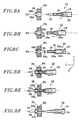
- les figures 8A à 8F sont respectivement des vues en coupe schématique qui représentent les étapes de connexion d'une extrémité quelconque de fibre de liaison dans un port de module de raccordement,
- les figures 9A et 9B sont respectivement des vues schématiques partielles du répartiteur de la figure 1 représentant sa liaison avec au moins un moyen de contrôle, la figure 9A illustrant une mesure de télésurveillance de fibre de liaison en fonctionnement, et la figure 9B illustrant un test de ligne sur défaut signalé.
- la zone comprise entre la première partie A du premier panneau de brassage B1 et la première partie A du second panneau de brassage B2 sert de zone fonctionnelle du répartiteur, c'est à dire qu'il s'agit d'une zone destinée à contenir les sur longueurs de fibres de liaison FL en fonctionnement qui relient un module de raccordement 12 d'un quelconque des dix-neuf premiers supports du panneau de brassage B1 à un module de raccordement 12 de l'un quelconque des dix-neuf premiers supports du panneau de brassage B2,
- la zone comprise entre la seconde partie B du panneau de brassage B1 et la seconde partie B du panneau de brassage B2 est destinée à venir en complément de la zone fonctionnelle, dans le cas par exemple où cette dernière serait entièrement utilisée,
- et la zone comprise entre la troisième partie C du premier panneau de brassage B1 et la troisième partie C du second panneau de brassage B2 sert de zone de stockage du répartiteur, c'est à dire qu'il s'agit d'une zone destinée à contenir les fibres de liaison FL non utilisées en attente de connexion dans la zone de fonctionnement. Il est fait en sorte qu'au fur et à mesure de leur stockage, les fibres de liaison FL sont installées l'une au dessus de l'autre dans la zone de stockage, à partir du port P8 du module 12 le plus bas du support 7 considéré dans le premier panneau de brassage B1 et du support 7 considéré dans le second panneau de brassage B2. Ainsi, une fois stockées, les fibres de liaison FL sont toutes parallèles.
Claims (18)
- Répartiteur de fibres optiques comprenant :caractérisé en ce que :des premier (B1) et second (B2) panneaux de brassage situés en vis-à-vis,au moins un premier support (7) de modules de raccordement (12) appartenant à chaque panneau, chaque module du premier panneau étant adapté pour être connecté à une extrémité d'une fibre optique (R) d'un premier groupe et chaque module du second panneau étant adapté pour être connecté à une extrémité d'une fibre optique (E) d'un second groupe, une fibre optique du premier groupe étant destinée à être reliée à une fibre optique du second groupe par l'intermédiaire d'une fibre de liaison (FL) qui comporte deux extrémités (e1, e2) reçues respectivement dans un port d'un des modules du premier panneau et dans un port d'un des modules du second panneau,
lesdits premier et second panneaux comportent chacun au moins un second support (7) de modules de raccordement, lesdits seconds supports coopérant entre eux pour former une zone de stockage de fibres de liaison (FL) non utilisées. - Répartiteur selon la revendication 1, dans lequel lesdits seconds supports sont agencés l'un en face de l'autre.
- Répartiteur selon la revendication 1 ou 2, dans lequel les fibres de liaison (FL) non utilisées sont reliées parallèlement les unes aux autres entre le second support (7) du premier panneau (B1) et le second support (7) du second panneau (B2), chaque fibre de liaison étant, au fur et à mesure du stockage, agencée directement au dessus de celle qui la précède.
- Répartiteur selon l'une quelconque des revendications 1 à 3, dans lequel les fibres de liaison (FL) ont toutes la même longueur.
- Répartiteur selon la revendication 1, dans lequel les premier et second panneaux de brassage possèdent chacun des premiers et seconds côtés opposés qui s'étendent respectivement selon des première (X) et seconde (Y) directions, les premier et second supports (7) de modules de raccordement du premier panneau de brassage, de même que les premier et second supports (7) de modules de raccordement du second panneau de brassage, étant montés à rotation autour d'un axe respectif (8) s'étendant selon la première direction (X), de telle sorte que chaque support (7) est adapté pour basculer entre une position de repos (PR), dans laquelle le support (7) s'étend vers l'extérieur du répartiteur en formant un angle (α) avec la seconde direction (Y), et une position de travail (PT), dans laquelle le support s'étend selon la seconde direction (Y).
- Répartiteur selon la revendication 1, dans lequel chacun des seconds supports (7) de modules de raccordement est agencé sur un côté du panneau de brassage qui lui est associé.
- Répartiteur selon la revendication 1, dans lequel les deux extrémités respectives (e1,20; e2,20) de chaque fibre de liaison (FL) s'étendent selon une troisième direction (Z).
- Répartiteur selon la revendication 1, dans lequel au moins un moyen de contrôle (31) est apte à tester à distance toute fibre optique (R) du premier groupe ou toute fibre optique (E) du second groupe, ou les deux, en continu ou sur défaut signalé.
- Procédé de connexion d'une fibre de liaison (FL) dans le répartiteur selon l'une quelconque des revendications 1 à 8,
comprenant les étappes suivantes:- a) on déplace le dispositif dans la zone de stockage.- b) on déconnecte une première extrémité (e1, 20) de fibre de liaison (FL) qui est connectée sur le second support (7) du premier panneau de brassage (B1) dans ladite zone de stockage,- c) on transfère ladite première extrémité (e1. 20) de fibre en direction du premier support (7) du premier panneau de brassage (B1),- d) on connecte ladite première extrémité (e1, 20) de fibre dans un port d'un module (12) dudit premier support,- e) on déplace le dispositif dans la zone de stockage,- f) on déconnecte une seconde extrémité (e2, 20) de fibre qui est connectée sur le second support (7) du second panneau de brassage (B2) dans ladite zone de stockage,- g) on transfère ladite seconde extrémité (e2, 20) de fibre en direction du premier support (7) du second panneau de brassage (B2),- h) on connecte ladite seconde extrémité (e2, 20) de fibre dans un port d'un module (12) dudit premier support (7) du second panneau de brassage (B2). - Procédé selon la revendication 9, dans lequel la fibre de liaison (FL) à déconnecter dans la zone de stockage est située au niveau le plus haut dans cette zone.
- Procédé selon la revendication 9, dans lequel la connexion de ladite fibre de liaison (FL) est effectuée au dessus du flot de fibres de liaison en fonctionnement.
- Procédé de déconnexion d'une fibre de liaison (FL) dans le répartiteur selon l'une quelconque des revendications 1 à 8,
comprenant les étappes suivantes :- a) on déplace le dispositif dans la zone comprise entre le premier support (7) du premier panneau de brassage (B1) et le premier support (7) du second panneau de brassage (B2),- b) on déconnecte une seconde extrémité (e2,20) de ladite fibre qui est connectée sur le premier support (7) du second panneau de brassage (B2),- c) on libère ladite seconde extrémité (e2,20) de fibre dans le flot de fibres de liaison (FL) en fonctionnement,- d) on déconnecte une première extrémité (e1, 20) de la fibre qui est connectée sur le premier support (7) du premier panneau de brassage (B1),- e) on extrait ladite fibre de liaison (FL) du répartiteur au moyen d'un dispositif d'extraction,- f) on connecte ladite fibre de liaison (FL) dans la zone de stockage. - Procédé selon la revendication 12, dans lequel l'étape e) consiste en une traction de ladite fibre de liaison (FL) par ladite première extrémité (e1, 20).
- Procédé selon la revendication 13, dans lequel la traction de la fibre de liaison (FL) est effectuée au dessus du premier panneau de brassage (B1).
- Procédé selon la revendication 12, dans lequel le dispositif d'extraction de fibre de liaison comprend une paire de rouleaux (29) entre lesquels passe ladite fibre de liaison (FL), lesdits rouleaux étant susceptibles d'être entraínés en rotation de façon à faire défiler ladite fibre de liaison.
- Procédé selon la revendication 15, dans lequel les rouleaux (29) sont recouverts d'une matière élastiquement déformable de façon à épouser la forme de ladite fibre de liaison lors de son passage entre les rouleaux.
- Procédé dans lequel aux étapes b) et f) du procédé selon la revendication 9 et aux étapes b) et d) du procédé selon la revendication 12 :- 1) on déplace le dispositif selon les première (X), seconde (Y) et troisième (Z) directions à proximité d'un port d'un module de raccordement d'un support (7) en position travail, port auquel est connectée ladite extrémité de fibre, afin de positionner l'élément de préhension (16) sensiblement dans l'axe dudit port,- 2) on déplace, selon la troisième direction (Z), le dispositif en direction du module de raccordement (12) jusqu'à ce que ladite extrémité de fibre pénètre dans la fente (19) de l'élément de préhension (16),- 3) on déplace, selon la première direction (X), l'élément de maintien (22) dans sa position de travail de façon à solidariser ladite extrémité de fibre avec ce dernier,- 4) on déplace, selon la troisième direction (Z), le dispositif dans la direction inverse de celle du module de raccordement (12), à une distance proche de ce dernier,- 5) on bascule ledit support (7) en position repos.
- Procédé, dans lequel, aux étapes d) et h) du procédé selon la revendication 9 et à l'étape f) du procédé selon la revendication 12,- 1) on déplace le dispositif selon les première (X), seconde (Y) et troisième (Z) directions à proximité d'un port d'un module de raccordement (12) du support (7) en position travail, port auquel est destinée à être connectée ladite extrémité de fibre, afin de positionner l'élément de préhension (16) sensiblement dans l'axe dudit port,- 2) on déplace, selon la première direction (X), ledit élément de maintien (22) dans sa position de repos de façon à désolidariser de l'élément de maintien (22) ladite extrémité de fibre à connecter,- 3) on déplace, selon la troisième direction (Z), l'élément poussoir (24) en direction du module de raccordement (12) de façon à faire sortir ladite extrémité de fibre de l'élément de préhension (16),- 4) on déplace, selon la troisième direction (Z), le dispositif en direction du module de raccordement (12) jusqu'à ce que ladite extrémité de fibre soit connectée à ce dernier,- 5) on déplace, selon la troisième direction (Z), le dispositif dans la direction inverse de celle du module de raccordement (12).
Applications Claiming Priority (3)
| Application Number | Priority Date | Filing Date | Title |
|---|---|---|---|
| FR0107032A FR2825476B1 (fr) | 2001-05-29 | 2001-05-29 | Repartiteur automatique de grande capacite, notamment pour fibres optiques, dispositif et procede de connexion/deconnexion automatique de fibres de liaison brassees dans ce repartiteur |
| FR0107032 | 2001-05-29 | ||
| PCT/FR2002/001750 WO2002097504A1 (fr) | 2001-05-29 | 2002-05-24 | Repartiteur automatique de grande capacite, notamment pour fibres optiques, dispositif et procede de connexion/deconnexion automatique de fibres de liaison brassees dans ce repartiteur |
Publications (2)
| Publication Number | Publication Date |
|---|---|
| EP1390791A1 EP1390791A1 (fr) | 2004-02-25 |
| EP1390791B1 true EP1390791B1 (fr) | 2005-12-14 |
Family
ID=8863754
Family Applications (1)
| Application Number | Title | Priority Date | Filing Date |
|---|---|---|---|
| EP02747487A Expired - Lifetime EP1390791B1 (fr) | 2001-05-29 | 2002-05-24 | Repartiteur automatique de grande capacite, notamment pour fibres optiques, dispositif et procede de connexion/deconnexion automatique de fibres de liaison brassees dans ce repartiteur |
Country Status (6)
| Country | Link |
|---|---|
| US (2) | US6973251B2 (fr) |
| EP (1) | EP1390791B1 (fr) |
| JP (1) | JP4102298B2 (fr) |
| DE (1) | DE60208020T2 (fr) |
| FR (1) | FR2825476B1 (fr) |
| WO (1) | WO2002097504A1 (fr) |
Families Citing this family (20)
| Publication number | Priority date | Publication date | Assignee | Title |
|---|---|---|---|---|
| FR2825476B1 (fr) * | 2001-05-29 | 2003-09-19 | France Telecom | Repartiteur automatique de grande capacite, notamment pour fibres optiques, dispositif et procede de connexion/deconnexion automatique de fibres de liaison brassees dans ce repartiteur |
| US6877906B2 (en) * | 2002-08-30 | 2005-04-12 | Nippon Telegraph And Telephone | Optical fiber cross-connect with a connection block, an alignment block and a handling device |
| CH697521B1 (de) * | 2005-01-19 | 2008-11-28 | Diamond Sa | Steckerteil für eine optische Steckverbindung. |
| US8068715B2 (en) | 2007-10-15 | 2011-11-29 | Telescent Inc. | Scalable and modular automated fiber optic cross-connect systems |
| US7747124B2 (en) * | 2008-06-30 | 2010-06-29 | Verizon Patent And Licensing Inc. | System and method for providing large scale, automated, fiber-optic, cross-connection |
| US8488938B2 (en) * | 2008-08-21 | 2013-07-16 | Telescent Inc. | Braided fiber optic cross-connect switches |
| EP2585867B1 (fr) * | 2010-06-24 | 2017-09-27 | Gigacom Benelux BVBA | Système de distribution de fibres optiques semi-automatisé |
| CN101923197A (zh) * | 2010-08-04 | 2010-12-22 | 南京华脉科技有限公司 | 光纤总配线架 |
| CN102938865B (zh) * | 2012-11-14 | 2015-07-15 | 北京邮电大学 | 一种自动网络配线装置和配线方法 |
| US9435975B2 (en) * | 2013-03-15 | 2016-09-06 | Commscope Technologies Llc | Modular high density telecommunications frame and chassis system |
| US10345526B2 (en) | 2014-12-14 | 2019-07-09 | Telescent Inc. | High reliability robotic cross-connect systems |
| CN104914536B (zh) * | 2015-06-04 | 2017-11-03 | 南京丰泰通信技术股份有限公司 | 一种适用于远程控制的滑动型智能光纤配线箱 |
| CN104914537B (zh) * | 2015-06-04 | 2018-03-06 | 南京丰泰通信技术股份有限公司 | 一种用于智能光纤配线箱的滑动型光纤跳纤装置 |
| WO2017200882A1 (fr) | 2016-05-18 | 2017-11-23 | Canon U.S.A., Inc. | Appareil et procédé d'accouplement et de désaccouplement à distance d'un connecteur |
| US11252488B2 (en) | 2017-10-09 | 2022-02-15 | Telescent Inc. | Incrementally scalable, two-tier system of robotic, fiber optic interconnect units enabling any-to-any connectivity |
| US20220132229A1 (en) * | 2016-10-10 | 2022-04-28 | Telescent, Inc. | Incrementally scalable, two-tier system of robotic, fiber optic interconnect units enabling any-to-any connectivity |
| WO2018071341A2 (fr) | 2016-10-10 | 2018-04-19 | Telescent Inc. | Système de répartiteurs de fibres robotiques à grande échelle utilisant une réservation de lignes de jonction multifibre |
| CN109001877B (zh) * | 2018-07-05 | 2020-03-13 | 江苏通鼎宽带有限公司 | 光缆交接箱及其自动跳接系统 |
| CN113534374B (zh) * | 2021-06-26 | 2022-06-14 | 华为技术有限公司 | 光纤配线设备和光纤调度系统 |
| CN117692056B (zh) * | 2024-01-31 | 2024-04-12 | 载荣建设(山东)有限公司 | 一种光纤通信用信号检测装置及其使用方法 |
Family Cites Families (15)
| Publication number | Priority date | Publication date | Assignee | Title |
|---|---|---|---|---|
| US5129030A (en) * | 1991-05-30 | 1992-07-07 | At&T Bell Laboratories | Movable lightguide connector panel |
| JPH05297296A (ja) * | 1992-04-23 | 1993-11-12 | Sumitomo Electric Ind Ltd | 光ファイバ配線切替装置 |
| EP0631165B1 (fr) * | 1993-05-10 | 1999-08-04 | Sumitomo Electric Industries, Limited | Appareil et procédé pour commuter des lignes de transmission optique |
| US5394503A (en) * | 1993-10-08 | 1995-02-28 | Data Switch Corporation | Optical fiber connection monitoring apparatus, patch panel control system and method of using same |
| JP3216692B2 (ja) * | 1995-01-23 | 2001-10-09 | 日本電信電話株式会社 | 光ファイバ接続替え装置及び方法 |
| JP3148609B2 (ja) * | 1995-12-08 | 2001-03-19 | 株式会社フジクラ | 光配線盤 |
| JP3173980B2 (ja) * | 1995-12-08 | 2001-06-04 | 株式会社フジクラ | 光配線盤 |
| US5701380A (en) * | 1996-06-24 | 1997-12-23 | Telect, Inc. | Fiber optic module for high density supply of patching and splicing |
| FR2764995B1 (fr) * | 1997-06-20 | 1999-07-23 | France Telecom | Repartiteur a haute densite et grande capacite, notamment pour fibres optiques |
| US6044193A (en) * | 1998-07-10 | 2000-03-28 | Siecor Operations, Llc | Fiber optic interconnection enclosure having a forced air system |
| KR100377823B1 (ko) * | 1998-07-24 | 2003-03-26 | 니폰덴신뎅와 가부시키가이샤 | 광배선반과 광배선 시스템 |
| US6721482B1 (en) * | 1998-09-10 | 2004-04-13 | Thomas A. Glynn | Telecommunications fiber optic infrastructure |
| US6760531B1 (en) * | 1999-03-01 | 2004-07-06 | Adc Telecommunications, Inc. | Optical fiber distribution frame with outside plant enclosure |
| US6532332B2 (en) * | 2001-02-15 | 2003-03-11 | Adc Telecommunications, Inc. | Cable guide for fiber termination block |
| FR2825476B1 (fr) * | 2001-05-29 | 2003-09-19 | France Telecom | Repartiteur automatique de grande capacite, notamment pour fibres optiques, dispositif et procede de connexion/deconnexion automatique de fibres de liaison brassees dans ce repartiteur |
-
2001
- 2001-05-29 FR FR0107032A patent/FR2825476B1/fr not_active Expired - Fee Related
-
2002
- 2002-05-24 JP JP2003500628A patent/JP4102298B2/ja not_active Expired - Fee Related
- 2002-05-24 EP EP02747487A patent/EP1390791B1/fr not_active Expired - Lifetime
- 2002-05-24 DE DE60208020T patent/DE60208020T2/de not_active Expired - Lifetime
- 2002-05-24 WO PCT/FR2002/001750 patent/WO2002097504A1/fr not_active Ceased
-
2003
- 2003-12-01 US US10/725,978 patent/US6973251B2/en not_active Expired - Fee Related
-
2005
- 2005-12-06 US US11/295,153 patent/US7292764B2/en not_active Expired - Fee Related
Also Published As
| Publication number | Publication date |
|---|---|
| WO2002097504A1 (fr) | 2002-12-05 |
| FR2825476B1 (fr) | 2003-09-19 |
| EP1390791A1 (fr) | 2004-02-25 |
| JP2004537742A (ja) | 2004-12-16 |
| US6973251B2 (en) | 2005-12-06 |
| US20060182406A1 (en) | 2006-08-17 |
| US7292764B2 (en) | 2007-11-06 |
| DE60208020D1 (de) | 2006-01-19 |
| DE60208020T2 (de) | 2006-08-24 |
| FR2825476A1 (fr) | 2002-12-06 |
| US20040136677A1 (en) | 2004-07-15 |
| JP4102298B2 (ja) | 2008-06-18 |
Similar Documents
| Publication | Publication Date | Title |
|---|---|---|
| WO2002097504A1 (fr) | Repartiteur automatique de grande capacite, notamment pour fibres optiques, dispositif et procede de connexion/deconnexion automatique de fibres de liaison brassees dans ce repartiteur | |
| EP0481901B1 (fr) | Procédés et dispositifs pour connecter automatiquement des extrémités de tronçons de fils conducteurs ou de fibres optiques à des réceptacles adaptés de composants | |
| FR2832225A1 (fr) | Repartiteur optique a haute densite et procede pour le jarretierage d'un tel repartiteur | |
| EP0348278A1 (fr) | Module de répartition et raccordement de fibres optiques | |
| EP0685599B1 (fr) | Système de transport sur un véhicule d'au moins deux travures de pontage destinées au franchissement de brèches et de dépose des travures au-dessus des brèches à partir du véhicule | |
| EP0886158A1 (fr) | Répartiteur à haute densité et grande capacité, notamment pour fibres optiques | |
| EP1044076B1 (fr) | Appareil de nettoyage de fibres ou filaments | |
| FR2693344A1 (fr) | Machine de repiquage automatique de mini-mottes. | |
| FR2553969A1 (fr) | Dispositif pour l'abattage des arbres | |
| FR2825477A1 (fr) | Dispositif de connexion/deconnexion automatique de fibres de liaison brassees dans un repartiteur de fibres optiques | |
| EP1222845B1 (fr) | Procédé pour séparer des mottes cubiques, dispositif pour la mise en oeuvre du procédé et machine de plantation de plantes en mottes comportant un tel dispositf | |
| EP0774415B1 (fr) | Procédé pour placer des clisses sur des bouteilles, machine automatique pour mettre en oeuvre ce procédé, empilage de clisses pour alimenter cette machine, procédé et machine pour réaliser ledit empilage | |
| FR2525402A1 (fr) | Procedes et appareils pour poser automatiquement des manchons sur des pieces de connexion equipant des extremites de fils ou de fibres | |
| FR2801168A1 (fr) | Procede pour separer des mottes cubiques, dispositif pour la mise en oeuvre du procede et machine de plantation de plants en mottes comportant un tel dispositif | |
| WO1984001768A1 (fr) | Outillage servant a preparer des cables optiques a plusieurs fibres en vue de leur aboutement fibre a fibre | |
| EP0490795B1 (fr) | Procédés et dispositifs pour fabriquer automatiquement des faisceaux arborescents de fils | |
| EP0803753B1 (fr) | Dispositif d'aide pour l'intervention et le rangement des fibres d'un câble optique | |
| EP0761085B1 (fr) | Remorque auto-chargeuse de balles de paille | |
| EP0252844B1 (fr) | Machine automatique pour le traitement d'un matériau en bande et notamment pour la découpe d'un tel matériau | |
| FR2478614A1 (fr) | Perfectionnements aux distributeurs de muselets | |
| FR2915703A1 (fr) | Procede et installation de changement de tete sur une machine de placement de fibres. | |
| FR2743690A1 (fr) | Remorque auto-chargeuse de balles de paille | |
| EP1026936B1 (fr) | Procede d'engainage de balles de vegetaux et materiels pour la mise en oeuvre du procede | |
| EP0790095B1 (fr) | Dispositif de positionnement et de maintien d'une cassette de façonnage sur le bâti d'une machine | |
| FR2668311A1 (fr) | Procedes et dispositifs pour connecter automatiquement des extremites de troncons de fils conducteurs ou de fibres optiques a des receptacles adaptes de composants. |
Legal Events
| Date | Code | Title | Description |
|---|---|---|---|
| PUAI | Public reference made under article 153(3) epc to a published international application that has entered the european phase |
Free format text: ORIGINAL CODE: 0009012 |
|
| 17P | Request for examination filed |
Effective date: 20031022 |
|
| AK | Designated contracting states |
Kind code of ref document: A1 Designated state(s): AT BE CH CY DE DK ES FI FR GB GR IE IT LI LU MC NL PT SE TR |
|
| AX | Request for extension of the european patent |
Extension state: AL LT LV MK RO SI |
|
| RIN1 | Information on inventor provided before grant (corrected) |
Inventor name: LE TRAON, GILLES Inventor name: BOUCHET, YOANN Inventor name: MORELLEC, DANIEL |
|
| GRAP | Despatch of communication of intention to grant a patent |
Free format text: ORIGINAL CODE: EPIDOSNIGR1 |
|
| RBV | Designated contracting states (corrected) |
Designated state(s): DE ES GB IT |
|
| GRAS | Grant fee paid |
Free format text: ORIGINAL CODE: EPIDOSNIGR3 |
|
| GRAA | (expected) grant |
Free format text: ORIGINAL CODE: 0009210 |
|
| AK | Designated contracting states |
Kind code of ref document: B1 Designated state(s): DE ES GB IT |
|
| PG25 | Lapsed in a contracting state [announced via postgrant information from national office to epo] |
Ref country code: IT Free format text: LAPSE BECAUSE OF FAILURE TO SUBMIT A TRANSLATION OF THE DESCRIPTION OR TO PAY THE FEE WITHIN THE PRESCRIBED TIME-LIMIT;WARNING: LAPSES OF ITALIAN PATENTS WITH EFFECTIVE DATE BEFORE 2007 MAY HAVE OCCURRED AT ANY TIME BEFORE 2007. THE CORRECT EFFECTIVE DATE MAY BE DIFFERENT FROM THE ONE RECORDED. Effective date: 20051214 |
|
| REG | Reference to a national code |
Ref country code: GB Ref legal event code: FG4D Free format text: NOT ENGLISH |
|
| REF | Corresponds to: |
Ref document number: 60208020 Country of ref document: DE Date of ref document: 20060119 Kind code of ref document: P |
|
| PG25 | Lapsed in a contracting state [announced via postgrant information from national office to epo] |
Ref country code: ES Free format text: LAPSE BECAUSE OF FAILURE TO SUBMIT A TRANSLATION OF THE DESCRIPTION OR TO PAY THE FEE WITHIN THE PRESCRIBED TIME-LIMIT Effective date: 20060325 |
|
| GBT | Gb: translation of ep patent filed (gb section 77(6)(a)/1977) |
Effective date: 20060316 |
|
| PLBE | No opposition filed within time limit |
Free format text: ORIGINAL CODE: 0009261 |
|
| STAA | Information on the status of an ep patent application or granted ep patent |
Free format text: STATUS: NO OPPOSITION FILED WITHIN TIME LIMIT |
|
| 26N | No opposition filed |
Effective date: 20060915 |
|
| REG | Reference to a national code |
Ref country code: GB Ref legal event code: 732E Free format text: REGISTERED BETWEEN 20101021 AND 20101027 |
|
| PGFP | Annual fee paid to national office [announced via postgrant information from national office to epo] |
Ref country code: DE Payment date: 20120531 Year of fee payment: 11 |
|
| PGFP | Annual fee paid to national office [announced via postgrant information from national office to epo] |
Ref country code: GB Payment date: 20120426 Year of fee payment: 11 |
|
| GBPC | Gb: european patent ceased through non-payment of renewal fee |
Effective date: 20130524 |
|
| PG25 | Lapsed in a contracting state [announced via postgrant information from national office to epo] |
Ref country code: DE Free format text: LAPSE BECAUSE OF NON-PAYMENT OF DUE FEES Effective date: 20131203 |
|
| REG | Reference to a national code |
Ref country code: DE Ref legal event code: R119 Ref document number: 60208020 Country of ref document: DE Effective date: 20131203 |
|
| PG25 | Lapsed in a contracting state [announced via postgrant information from national office to epo] |
Ref country code: GB Free format text: LAPSE BECAUSE OF NON-PAYMENT OF DUE FEES Effective date: 20130524 |