EP1389565A1 - Kameraanordnung für Kraftfahrzeuge - Google Patents
Kameraanordnung für Kraftfahrzeuge Download PDFInfo
- Publication number
- EP1389565A1 EP1389565A1 EP03102436A EP03102436A EP1389565A1 EP 1389565 A1 EP1389565 A1 EP 1389565A1 EP 03102436 A EP03102436 A EP 03102436A EP 03102436 A EP03102436 A EP 03102436A EP 1389565 A1 EP1389565 A1 EP 1389565A1
- Authority
- EP
- European Patent Office
- Prior art keywords
- camera
- optical guide
- disc
- arrangement according
- guide element
- Prior art date
- Legal status (The legal status is an assumption and is not a legal conclusion. Google has not performed a legal analysis and makes no representation as to the accuracy of the status listed.)
- Granted
Links
Images



Classifications
-
- B—PERFORMING OPERATIONS; TRANSPORTING
- B60—VEHICLES IN GENERAL
- B60S—SERVICING, CLEANING, REPAIRING, SUPPORTING, LIFTING, OR MANOEUVRING OF VEHICLES, NOT OTHERWISE PROVIDED FOR
- B60S1/00—Cleaning of vehicles
- B60S1/02—Cleaning windscreens, windows or optical devices
- B60S1/04—Wipers or the like, e.g. scrapers
- B60S1/06—Wipers or the like, e.g. scrapers characterised by the drive
- B60S1/08—Wipers or the like, e.g. scrapers characterised by the drive electrically driven
- B60S1/0818—Wipers or the like, e.g. scrapers characterised by the drive electrically driven including control systems responsive to external conditions, e.g. by detection of moisture, dirt or the like
- B60S1/0822—Wipers or the like, e.g. scrapers characterised by the drive electrically driven including control systems responsive to external conditions, e.g. by detection of moisture, dirt or the like characterized by the arrangement or type of detection means
- B60S1/0874—Wipers or the like, e.g. scrapers characterised by the drive electrically driven including control systems responsive to external conditions, e.g. by detection of moisture, dirt or the like characterized by the arrangement or type of detection means characterized by the position of the sensor on the windshield
- B60S1/0881—Wipers or the like, e.g. scrapers characterised by the drive electrically driven including control systems responsive to external conditions, e.g. by detection of moisture, dirt or the like characterized by the arrangement or type of detection means characterized by the position of the sensor on the windshield characterized by the attachment means on the windshield
-
- B—PERFORMING OPERATIONS; TRANSPORTING
- B60—VEHICLES IN GENERAL
- B60R—VEHICLES, VEHICLE FITTINGS, OR VEHICLE PARTS, NOT OTHERWISE PROVIDED FOR
- B60R11/00—Arrangements for holding or mounting articles, not otherwise provided for
- B60R11/04—Mounting of cameras operative during drive; Arrangement of controls thereof relative to the vehicle
-
- B—PERFORMING OPERATIONS; TRANSPORTING
- B60—VEHICLES IN GENERAL
- B60S—SERVICING, CLEANING, REPAIRING, SUPPORTING, LIFTING, OR MANOEUVRING OF VEHICLES, NOT OTHERWISE PROVIDED FOR
- B60S1/00—Cleaning of vehicles
- B60S1/02—Cleaning windscreens, windows or optical devices
- B60S1/04—Wipers or the like, e.g. scrapers
- B60S1/06—Wipers or the like, e.g. scrapers characterised by the drive
- B60S1/08—Wipers or the like, e.g. scrapers characterised by the drive electrically driven
- B60S1/0818—Wipers or the like, e.g. scrapers characterised by the drive electrically driven including control systems responsive to external conditions, e.g. by detection of moisture, dirt or the like
- B60S1/0822—Wipers or the like, e.g. scrapers characterised by the drive electrically driven including control systems responsive to external conditions, e.g. by detection of moisture, dirt or the like characterized by the arrangement or type of detection means
-
- B—PERFORMING OPERATIONS; TRANSPORTING
- B60—VEHICLES IN GENERAL
- B60S—SERVICING, CLEANING, REPAIRING, SUPPORTING, LIFTING, OR MANOEUVRING OF VEHICLES, NOT OTHERWISE PROVIDED FOR
- B60S1/00—Cleaning of vehicles
- B60S1/02—Cleaning windscreens, windows or optical devices
- B60S1/04—Wipers or the like, e.g. scrapers
- B60S1/06—Wipers or the like, e.g. scrapers characterised by the drive
- B60S1/08—Wipers or the like, e.g. scrapers characterised by the drive electrically driven
- B60S1/0818—Wipers or the like, e.g. scrapers characterised by the drive electrically driven including control systems responsive to external conditions, e.g. by detection of moisture, dirt or the like
- B60S1/0822—Wipers or the like, e.g. scrapers characterised by the drive electrically driven including control systems responsive to external conditions, e.g. by detection of moisture, dirt or the like characterized by the arrangement or type of detection means
- B60S1/0833—Optical rain sensor
- B60S1/0844—Optical rain sensor including a camera
-
- G—PHYSICS
- G06—COMPUTING OR CALCULATING; COUNTING
- G06V—IMAGE OR VIDEO RECOGNITION OR UNDERSTANDING
- G06V20/00—Scenes; Scene-specific elements
- G06V20/50—Context or environment of the image
- G06V20/56—Context or environment of the image exterior to a vehicle by using sensors mounted on the vehicle
-
- B—PERFORMING OPERATIONS; TRANSPORTING
- B60—VEHICLES IN GENERAL
- B60R—VEHICLES, VEHICLE FITTINGS, OR VEHICLE PARTS, NOT OTHERWISE PROVIDED FOR
- B60R11/00—Arrangements for holding or mounting articles, not otherwise provided for
- B60R2011/0001—Arrangements for holding or mounting articles, not otherwise provided for characterised by position
- B60R2011/0003—Arrangements for holding or mounting articles, not otherwise provided for characterised by position inside the vehicle
- B60R2011/0026—Windows, e.g. windscreen
-
- B—PERFORMING OPERATIONS; TRANSPORTING
- B60—VEHICLES IN GENERAL
- B60R—VEHICLES, VEHICLE FITTINGS, OR VEHICLE PARTS, NOT OTHERWISE PROVIDED FOR
- B60R11/00—Arrangements for holding or mounting articles, not otherwise provided for
- B60R2011/0042—Arrangements for holding or mounting articles, not otherwise provided for characterised by mounting means
- B60R2011/0049—Arrangements for holding or mounting articles, not otherwise provided for characterised by mounting means for non integrated articles
- B60R2011/005—Connection with the vehicle part
- B60R2011/0063—Connection with the vehicle part using adhesive means, e.g. hook and loop fasteners
-
- B—PERFORMING OPERATIONS; TRANSPORTING
- B60—VEHICLES IN GENERAL
- B60R—VEHICLES, VEHICLE FITTINGS, OR VEHICLE PARTS, NOT OTHERWISE PROVIDED FOR
- B60R11/00—Arrangements for holding or mounting articles, not otherwise provided for
- B60R2011/0042—Arrangements for holding or mounting articles, not otherwise provided for characterised by mounting means
- B60R2011/0049—Arrangements for holding or mounting articles, not otherwise provided for characterised by mounting means for non integrated articles
- B60R2011/0064—Connection with the article
- B60R2011/0077—Connection with the article using adhesive means, e.g. hook and loop fasteners
-
- B—PERFORMING OPERATIONS; TRANSPORTING
- B60—VEHICLES IN GENERAL
- B60S—SERVICING, CLEANING, REPAIRING, SUPPORTING, LIFTING, OR MANOEUVRING OF VEHICLES, NOT OTHERWISE PROVIDED FOR
- B60S1/00—Cleaning of vehicles
- B60S1/02—Cleaning windscreens, windows or optical devices
- B60S1/04—Wipers or the like, e.g. scrapers
- B60S1/06—Wipers or the like, e.g. scrapers characterised by the drive
- B60S1/08—Wipers or the like, e.g. scrapers characterised by the drive electrically driven
- B60S1/0818—Wipers or the like, e.g. scrapers characterised by the drive electrically driven including control systems responsive to external conditions, e.g. by detection of moisture, dirt or the like
- B60S1/0822—Wipers or the like, e.g. scrapers characterised by the drive electrically driven including control systems responsive to external conditions, e.g. by detection of moisture, dirt or the like characterized by the arrangement or type of detection means
- B60S1/0874—Wipers or the like, e.g. scrapers characterised by the drive electrically driven including control systems responsive to external conditions, e.g. by detection of moisture, dirt or the like characterized by the arrangement or type of detection means characterized by the position of the sensor on the windshield
- B60S1/0885—Wipers or the like, e.g. scrapers characterised by the drive electrically driven including control systems responsive to external conditions, e.g. by detection of moisture, dirt or the like characterized by the arrangement or type of detection means characterized by the position of the sensor on the windshield the sensor being integrated in a rear-view mirror module
Definitions
- the invention relates to a camera arrangement for motor vehicles with a camera, which is arranged in the vehicle interior behind a disc.
- a camera arrangement is known for example from DE 40 16 570 A1.
- With such Camera arrangement are a variety of video surveillance of the vehicle exterior or also an automatic lane detection possible.
- the use of cameras in vehicles will increase in the future.
- Such a rain sensor is known for example from DE 199 55 423 A1 known.
- infrared measuring radiation from a transmitter via an optical guide element coupled into the windshield.
- the so coupled Radiation is reflected at the interface of the disk outside by total reflection and directed via a further optical guide element in the direction of a receiver.
- the total reflection condition becomes in the presence of precipitation on the disc disturbed, so that the proportion of the reflected radiation and thus the signal in the receiver decreases, whereupon ultimately the principle of this rain sensor is based.
- the two optical Guiding elements are directly or indirectly, e.g. via an optical coupling medium (e.g. a silicone layer or adhesive layer) on the disc, the disc, the optical guide elements and possibly the optical coupling medium at least similar Have refractive indices for the relevant radiation.
- an optical coupling medium e.g. a silicone layer or adhesive layer
- the object of the invention is to provide a camera arrangement under cost and simple inclusion of at least one optical guide element for one of Camera independent sensor device.
- a support plate is provided, which is attached to the inside of the disc and serves as a holder for the camera, wherein with the support plate at least one matter-bound optical guide element for a connected by the camera sensor device is connected, preferably with the The support plate is flush.
- This carrier plate with the at least one optical Guide element is then directly or via an optical coupling medium on the Disc inside brought to the plant. This will make an easy-to-use one and compact camera arrangement, in which one or more optical guide elements are already integrated for an additional sensor device.
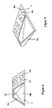
- Figure 1 shows a support plate (3), which serves as a holder for the camera (1) and at the Inside the windshield (2) is attached.
- the support plate (3) has a preferably funnel-shaped Cover (3A) integrally formed, which the space between disc (2) and Camera lens (1A) or the lens barrel light and dust tight surrounds.
- the camera or the camera housing (1) is at the end facing away from the disc (2) funnel-shaped cap (3A) arranged (see Figures 3, 4 and 9).
- the one in the direction of the disc (2) tapered away formed funnel (3A) thus also defines the Light detection area of the camera (1).
- the carrier plate 3 has a light entry window 3B.
- the support plate (3) so on the disc (2) rests that the cap (3A) in Area of the light entry window (3 B) of the disc (2) is closed.
- the Disc (2) facing away from the funnel-shaped cap (3A) has a recess (3C) for light and dust-tight recording of the camera lens or the lens barrel (1A) on.
- the connection between the cap (3A) and the camera or the camera body (1) via a ball joint is used the adjustment.
- the socket (3D) and the ball segment become (1B) connected by laser welding.
- the ball segment (1B) is located in welded state dust-tight to the socket (3D).
- the center of the ball joint lies on the optical axis of the objective (1A), whereby a very compact design of the camera arrangement is achieved. This is achieved by in that the objective or the lens barrel (1A) is concentric within the sphere segment (1B) is arranged.
- the socket (3D) of the cap (3) a concentric clear recess (3C) for the lens (1A).
- the optical Guiding elements (4A, 4B) formed integrally with the support plate (3) for the camera (1).
- the illustrated optical guide elements (4A, 4B) are part of a rain sensor, which is the Precipitation detection on the disc is used.
- the optical guide elements (4A, 4B) close on one side flush with the support plate (3), so that they directly with the optical guide elements or indirectly via an optical coupling medium (not shown) on the disk inside can be brought to the plant.
- On the side facing away from the disc (2) have the optical guide elements (4A, 4B) has a curvature (not shown) for formation a lens.
- the optical guide elements (4A, 4B) are preferably in a two-component injection molding process made in one piece with the carrier plate (3), wherein the carrier plate made a plastic material which is impermeable to visible radiation and to the measuring radiation is made while the optical guide elements from a for the measuring radiation made of transparent plastic material.
- the rain sensor becomes infrared Light used as measuring radiation.
- the on the support plate (3), preferably in Injection molding, molded cap (3A) consists - as the carrier platesaus a visible light impermeable plastic material so that the space between Washer (2) and camera lens (1A) is enclosed light-tight.
- the carrier plate has at least one optical Guide element on, the part of an apron and / or ambient light sensor for automatic driving light circuit is, wherein the optical guide element the apron and / or Ambient light directed to an associated receiver.
- the optical guide elements are not formed integrally with the carrier plate.
- this is at least an optical guide element via a connecting means, in particular via a Locking connection, connected to the support plate for the camera.
- a connecting means in particular via a Locking connection
- the support plate for the camera For that purpose that is at least one optical guide element part of a second carrier plate, which then has a Connecting means is connected to the support plate for the camera.
- the attachment of the support plate (3) on the disc (2) is preferably carried out via a Fixing ring (not shown), which is glued to the disc (2), wherein the support plate (3) for the camera (1) via a force acting on the fastening ring spring against the Disc is pressed. It can between disc and carrier plate / guide elements another coupling medium transparent to the measuring radiation, e.g. a silicone layer, be arranged. In an alternative embodiment, the carrier plate itself to the Slice glued on.
- a support plate (3) is shown, on the two cover caps (3A) for each one Camera (1) are arranged.
- the optical guide elements (4A, 4B) are between the both light entry windows (3B) of the cover (3A) arranged.
- the optical guide elements can basically arbitrarily on the support plate to the Be arranged light entrance window around, both around the light entrance window around as well as on one side of it.
- the camera comprises at least one objective and a photosensitive semiconductor chip.
- the carrier plate has a side edge opposite the base - in which the optical guide elements are arranged flush - Projecting, circumferential collar on, which serves as a boundary frame for a curing Potting compound is used, which forms the coupling medium.
Landscapes
- Engineering & Computer Science (AREA)
- Mechanical Engineering (AREA)
- Automation & Control Theory (AREA)
- Physics & Mathematics (AREA)
- General Physics & Mathematics (AREA)
- Multimedia (AREA)
- Theoretical Computer Science (AREA)
- Studio Devices (AREA)
- Fittings On The Vehicle Exterior For Carrying Loads, And Devices For Holding Or Mounting Articles (AREA)
Abstract
Description
- Figur 1
- eine perspektivische Ansicht einer Trägerplatte für die Kamera mit darin einstückig integrierten optischen Führungselementen für einen Regensensor,
- Figur 2
- eine Draufsicht auf die Trägerplatte von Figur 1,
- Figur 3
- eine Draufsicht auf die Trägerplatte von Figur 1, jedoch mit Einblick in die trichterförmige Abdeckkappe,
- Figur 4
- eine Seitenansicht der an der Scheibeninnenseite angeordneten Trägerplatte mit daran angeformter Abdeckkappe,
- Figur 5
- eine perspektivische Ansicht einer Trägerplatte für die Kamera mit darin einstückig integrierten optischen Führungselementen für einen Regensensor, wobei die Anordnung der optischen Führungselemente gegenüber der Trägerplatte von Figur 1 verschieden ist,
- Figur 6
- eine Draufsicht auf die Trägerplatte von Figur 5,
- Figur 7
- eine perspektivische Ansicht einer Trägerplatte für zwei Kameras mit darin einstückig integrierten optischen Führungselementen für einen Regensensor,
- Figur 8
- die Schnittdarstellung einer Trägerplatte mit daran angeformter Abdeckkappe sowie der Kamera in Explosionsdarstellung.
- 1)
- Kamera
- 1A)
- Kameraobjektiv
- 1B)
- Kugelsegment auf der Kamera
- 2)
- Scheibe
- 3)
- Trägerplatte
- 3A)
- Abdeckkappe
- 3B)
- Lichteintrittsfenster in der Trägerplatte
- 3C)
- Aussparung in der trichterförmigen Abdeckkappe zur Aufnahme des Kameraobjektivs
- 4A,4B)
- Optische Führungselemente in der Trägerplatte
Claims (16)
- Kameraanordnung für Kraftfahrzeuge mit einer Kamera (1), die im Fahrzeuginnenraum hinter einer Scheibe (2) angeordnet ist,
dadurch gekennzeichnet, daßeine Trägerplatte (3) vorgesehen ist, die an der Innenseite der Scheibe (2) befestigt ist und als Halterung für die Kamera (1) dient,mit der Trägerplatte (3) mindestens ein materiegebundenes optisches Führungselement (4A,4B) für eine von der Kamera (1) unabhängige Sensoreinrichtung verbunden ist,die Trägerplatte (3) mit dem mindestens einen optischen Führungselement (4A,4B) direkt oder indirekt über ein optisches Koppelmedium an der Scheibeninnenseite anliegt. - Kameraanordnung nach Anspruch 1,
dadurch gekennzeichnet, daß das optische Führungselement (4A,4B) bündig mit der Trägerplatte (3) abschließt, - Kameraanordnung nach Anspruch 1 oder 2,
dadurch gekennzeichnet, daß das mindestens eine optische Führungselement (4A,4B) einstückig mit der Trägerplatte (3) für die Kamera (1) ausgebildet ist. - Kameraanordnung nach Anspruch 1 oder 2,
dadurch gekennzeichnet, daß das mindestens eine optische Führungselement (4A,4B) über ein Verbindungselement, insbesondere eine Rastverbindung, mit der Trägerplatte (3) für die Kamera (1) verbunden ist. - Kameraanordnung nach Anspruch 4,
dadurch gekennzeichnet, daß das mindestens eine optische Führungselement (4A,4B) Teil einer zweiten Trägerplatte ist, die über ein Verbindungselement, insbesondere eine Rastverbindung, mit der Trägerplatte (3) für die Kamera (1) verbunden ist. - Kameraanordnung nach einem der vorstehenden Ansprüche,
dadurch gekennzeichnet, daß an der Scheibe (2) ein Befestigungselement, insbesondere ein Befestigungsring angeklebt ist, wobei die Trägerplatte (3) für die Kamera (1) über eine an dem Befestigungselement angreifende Feder gegen die Scheibe (2) gedrückt wird. - Kameraanordnung nach einem der vorstehenden Ansprüche 1 bis 5,
dadurch gekennzeichnet, daß die Trägerplatte (3) an die Scheibe (1) geklebt ist. - Kameraanordnung nach einem der vorstehenden Ansprüche,
dadurch gekennzeichnet, daßan der Trägerplatte (3) eine Abdeckkappe (3A) angeformt ist, welche den Raum zwischen Scheibe (2) und Kameraobjektiv (1A) licht- und staubdicht umschließt, wobei die Kamera (1) an dem der Scheibe (2) abgewandten Ende der Abdeckkappe (3A) angeordnet ist,die Trägerplatte (3) ein Lichteintrittsfenster (3B) aufweist,die Trägerplatte (3) so an der Scheibe (2) anliegt, daß die Abdeckkappe (3A) im Bereich des Lichteintrittsfensters (3B) von der Scheibe (2) verschlossen wird. - Kameraanordnung nach Anspruch 8,
dadurch gekennzeichnet, daß die Abdeckkappe (3A) in Form eines Trichters ausgebildet ist, der in Richtung von der Scheibe weg verjüngt ausgebildet ist. - Kameraanordnung nach Anspruch 8 oder 9,
dadurch gekennzeichnet, daß die Abdeckkappe (3A) an ihrem der Scheibe abgewandten Ende eine Aussparung (3C) zur licht- und staubdichten Aufnahme des Kameraobjektivs (1A) aufweist. - Kameraanordnung nach einem der vorstehenden Ansprüche,
dadurch gekennzeichnet, daß das mindestens eine optische Führungselement (4A,4B) Teil eines Regensensors zur Niederschlagserfassung auf der Scheibe ist. - Kameraanordnung nach Anspruch 11,
dadurch gekennzeichnet, daß wenigstens ein optisches Führungselemente-Paar (4A,4B) vorgesehen ist, wobei das eine optische Führungselement (4A) der Einkopplung von Meßstrahlung aus einem Sender in die Scheibe (2) dient, während das andere optische Führungselement (4B) der Auskopplung der an der Scheibenaußenseite reflektierten Meßstrahlung in Richtung auf einen Empfänger dient. - Kameraanordnung nach einem der vorstehenden Ansprüche,
dadurch gekennzeichnet, daß das mindestens eine optische Führungselement (4A,4B) Teil eines Vorfeld- und/oder Umgebungslichtsensors zur automatischen Fahrlichtschaltung ist, wobei das mindestens eine optische Führungselement das Vorfeld- und/oder Umgebungslicht auf einen zugeordneten Empfänger richtet. - Kameraanordnung nach Anspruch 2 oder nach einem der Ansprüche 6 bis 13,
dadurch gekennzeichnet, daß die Trägerplatte (3) für die Kamera (1) bis auf das mindestens eine optische Führungselement (4A,4B) aus einem nicht transparenten Material besteht. - Kameraanordnung nach Anspruch 14,
dadurch gekennzeichnet, daß die Trägerplatte (3) aus einem für sichtbares Licht nicht transparenten Material besteht. - Kameraanordnung nach Anspruch 14 oder 15,
dadurch gekennzeichnet, daß die Trägerplatte (3) aus einem für infrarotes Licht nicht transparenten Material besteht.
Priority Applications (2)
| Application Number | Priority Date | Filing Date | Title |
|---|---|---|---|
| EP05110596A EP1623876A3 (de) | 2002-08-16 | 2003-08-06 | Kameraanordnung für Kraftfahrzeuge |
| EP05110590A EP1627775A3 (de) | 2002-08-16 | 2003-08-06 | Kameraanordnung für Kraftfahrzeuge mit einer Kamera |
Applications Claiming Priority (2)
| Application Number | Priority Date | Filing Date | Title |
|---|---|---|---|
| DE10237481A DE10237481A1 (de) | 2002-08-16 | 2002-08-16 | Kameraanordnung für Kraftfahrzeuge |
| DE10237481 | 2002-08-16 |
Related Child Applications (2)
| Application Number | Title | Priority Date | Filing Date |
|---|---|---|---|
| EP05110590A Division EP1627775A3 (de) | 2002-08-16 | 2003-08-06 | Kameraanordnung für Kraftfahrzeuge mit einer Kamera |
| EP05110596A Division EP1623876A3 (de) | 2002-08-16 | 2003-08-06 | Kameraanordnung für Kraftfahrzeuge |
Publications (2)
| Publication Number | Publication Date |
|---|---|
| EP1389565A1 true EP1389565A1 (de) | 2004-02-18 |
| EP1389565B1 EP1389565B1 (de) | 2006-12-20 |
Family
ID=30469760
Family Applications (3)
| Application Number | Title | Priority Date | Filing Date |
|---|---|---|---|
| EP05110590A Withdrawn EP1627775A3 (de) | 2002-08-16 | 2003-08-06 | Kameraanordnung für Kraftfahrzeuge mit einer Kamera |
| EP05110596A Withdrawn EP1623876A3 (de) | 2002-08-16 | 2003-08-06 | Kameraanordnung für Kraftfahrzeuge |
| EP03102436A Expired - Lifetime EP1389565B1 (de) | 2002-08-16 | 2003-08-06 | Kameraanordnung für Kraftfahrzeuge |
Family Applications Before (2)
| Application Number | Title | Priority Date | Filing Date |
|---|---|---|---|
| EP05110590A Withdrawn EP1627775A3 (de) | 2002-08-16 | 2003-08-06 | Kameraanordnung für Kraftfahrzeuge mit einer Kamera |
| EP05110596A Withdrawn EP1623876A3 (de) | 2002-08-16 | 2003-08-06 | Kameraanordnung für Kraftfahrzeuge |
Country Status (2)
| Country | Link |
|---|---|
| EP (3) | EP1627775A3 (de) |
| DE (2) | DE10237481A1 (de) |
Cited By (10)
| Publication number | Priority date | Publication date | Assignee | Title |
|---|---|---|---|---|
| WO2005113293A1 (de) * | 2004-05-19 | 2005-12-01 | Leopold Kostal Gmbh & Co. Kg | Kameraanordnung für ein kraftfahrzeug |
| WO2010121982A1 (de) * | 2009-04-23 | 2010-10-28 | Saint-Gobain Glass France | Fahrzeugverglasung, verfahren zu dessen herstellung und verwendung |
| CN103940740A (zh) * | 2013-01-17 | 2014-07-23 | 赫拉胡克公司 | 用于检测嵌板上的湿度的传感器装置 |
| US9637053B2 (en) | 1999-11-04 | 2017-05-02 | Magna Electronics Inc. | Accessory mounting system for a vehicle |
| US9718357B2 (en) | 1997-08-25 | 2017-08-01 | Magna Electronics Inc. | Vehicular accessory system |
| US9783125B2 (en) | 2000-03-31 | 2017-10-10 | Magna Electronics Inc. | Accessory system for a vehicle |
| US9862323B2 (en) | 2002-01-31 | 2018-01-09 | Magna Electronics Inc. | Vehicle accessory system |
| US10046714B2 (en) | 2004-12-15 | 2018-08-14 | Magna Electronics Inc. | Accessory mounting system for a vehicle |
| US10773724B2 (en) | 2004-08-18 | 2020-09-15 | Magna Electronics Inc. | Accessory system for vehicle |
| CN116670581A (zh) * | 2021-03-15 | 2023-08-29 | 深圳市大疆创新科技有限公司 | 成像装置及可移动平台 |
Families Citing this family (14)
| Publication number | Priority date | Publication date | Assignee | Title |
|---|---|---|---|---|
| US6326613B1 (en) | 1998-01-07 | 2001-12-04 | Donnelly Corporation | Vehicle interior mirror assembly adapted for containing a rain sensor |
| US8288711B2 (en) | 1998-01-07 | 2012-10-16 | Donnelly Corporation | Interior rearview mirror system with forwardly-viewing camera and a control |
| US6445287B1 (en) | 2000-02-28 | 2002-09-03 | Donnelly Corporation | Tire inflation assistance monitoring system |
| US6278377B1 (en) | 1999-08-25 | 2001-08-21 | Donnelly Corporation | Indicator for vehicle accessory |
| US6420975B1 (en) | 1999-08-25 | 2002-07-16 | Donnelly Corporation | Interior rearview mirror sound processing system |
| DE102005014961A1 (de) * | 2005-04-01 | 2006-10-05 | Hella Kgaa Hueck & Co. | Befestigung elektronischer Bauteile im Bereich der Windschutzscheibe eines Fahrzeugs |
| JP4848795B2 (ja) * | 2006-02-27 | 2011-12-28 | パナソニック株式会社 | ステレオカメラ |
| DE102007020912A1 (de) | 2007-05-04 | 2008-11-06 | GM Global Technology Operations, Inc., Detroit | Kraftfahrzeug mit einer Kamera und einem Scheibenwischer |
| US8570374B2 (en) | 2008-11-13 | 2013-10-29 | Magna Electronics Inc. | Camera for vehicle |
| KR101698783B1 (ko) * | 2013-12-16 | 2017-01-23 | 엘지전자 주식회사 | 스테레오 카메라 및 이를 구비한 차량 |
| DE102015007830B4 (de) * | 2015-06-18 | 2017-12-28 | e.solutions GmbH | Optische Baugruppe, elektronisches Gerät und Kraftfahrzeug mit einer optischen Baugruppe sowie Verfahren zum Herstellen einer optischen Baugruppe |
| DE102022123456A1 (de) | 2022-09-14 | 2024-03-14 | Valeo Schalter Und Sensoren Gmbh | Einrichtung für ein fahrzeug |
| EP4586006A1 (de) * | 2024-01-11 | 2025-07-16 | Aptiv Technologies AG | Gehäuse für eine kameraanordnung und kameraanordnung |
| DE102024120595A1 (de) * | 2024-07-19 | 2026-01-22 | Valeo Schalter Und Sensoren Gmbh | Sensorbaugruppe für ein Kraftfahrzeug und Kraftfahrzeug |
Citations (3)
| Publication number | Priority date | Publication date | Assignee | Title |
|---|---|---|---|---|
| DE4329983A1 (de) * | 1993-09-04 | 1995-03-09 | Bosch Gmbh Robert | Dachmodul für ein Kraftfahrzeug |
| DE19647200C1 (de) * | 1996-11-15 | 1998-01-08 | Kostal Leopold Gmbh & Co Kg | Gehäuse für Dachmodul |
| US6170955B1 (en) * | 1998-02-27 | 2001-01-09 | Iteris, Inc. | Vehicle mounted optical assembly |
Family Cites Families (4)
| Publication number | Priority date | Publication date | Assignee | Title |
|---|---|---|---|---|
| JP2920653B2 (ja) * | 1990-03-15 | 1999-07-19 | アイシン精機株式会社 | 車載撮像装置 |
| DE19753879C1 (de) * | 1997-12-05 | 1998-12-03 | Kostal Leopold Gmbh & Co Kg | Dachmodul |
| DE19955423A1 (de) * | 1999-11-18 | 2001-05-31 | Hella Kg Hueck & Co | Sensoreinrichtung und Verfahren zur Herstellung einer Sensoreinrichtung |
| US6392218B1 (en) * | 2000-04-07 | 2002-05-21 | Iteris, Inc. | Vehicle rain sensor |
-
2002
- 2002-08-16 DE DE10237481A patent/DE10237481A1/de not_active Withdrawn
-
2003
- 2003-08-06 EP EP05110590A patent/EP1627775A3/de not_active Withdrawn
- 2003-08-06 EP EP05110596A patent/EP1623876A3/de not_active Withdrawn
- 2003-08-06 EP EP03102436A patent/EP1389565B1/de not_active Expired - Lifetime
- 2003-08-06 DE DE50306013T patent/DE50306013D1/de not_active Expired - Lifetime
Patent Citations (3)
| Publication number | Priority date | Publication date | Assignee | Title |
|---|---|---|---|---|
| DE4329983A1 (de) * | 1993-09-04 | 1995-03-09 | Bosch Gmbh Robert | Dachmodul für ein Kraftfahrzeug |
| DE19647200C1 (de) * | 1996-11-15 | 1998-01-08 | Kostal Leopold Gmbh & Co Kg | Gehäuse für Dachmodul |
| US6170955B1 (en) * | 1998-02-27 | 2001-01-09 | Iteris, Inc. | Vehicle mounted optical assembly |
Cited By (22)
| Publication number | Priority date | Publication date | Assignee | Title |
|---|---|---|---|---|
| US9718357B2 (en) | 1997-08-25 | 2017-08-01 | Magna Electronics Inc. | Vehicular accessory system |
| US9637053B2 (en) | 1999-11-04 | 2017-05-02 | Magna Electronics Inc. | Accessory mounting system for a vehicle |
| US10059265B2 (en) | 2000-03-02 | 2018-08-28 | Magna Electronics Inc. | Vision system for a vehicle |
| US10427604B2 (en) | 2000-03-02 | 2019-10-01 | Magna Electronics Inc. | Vision system for a vehicle |
| US9843777B2 (en) | 2000-03-02 | 2017-12-12 | Magna Electronics Inc. | Cabin monitoring system for a vehicle |
| US9783125B2 (en) | 2000-03-31 | 2017-10-10 | Magna Electronics Inc. | Accessory system for a vehicle |
| US10543786B2 (en) | 2002-01-31 | 2020-01-28 | Magna Electronics Inc. | Vehicle camera system |
| US9862323B2 (en) | 2002-01-31 | 2018-01-09 | Magna Electronics Inc. | Vehicle accessory system |
| WO2005113293A1 (de) * | 2004-05-19 | 2005-12-01 | Leopold Kostal Gmbh & Co. Kg | Kameraanordnung für ein kraftfahrzeug |
| CN100540362C (zh) * | 2004-05-19 | 2009-09-16 | 利奥波德·科世达责任有限股份公司 | 用于机动车的照相机系统 |
| JP2008500926A (ja) * | 2004-05-19 | 2008-01-17 | レオポルト・コスタール・ゲゼルシヤフト・ミト・ベシユレンクテル・ハフツング・ウント・コンパニー・コマンデイトゲゼルシヤフト | 車両用のカメラ配置 |
| US7322755B2 (en) | 2004-05-19 | 2008-01-29 | Leopold Kostal Gmbh & Co. Kg | Camera arrangement for a motor vehicle |
| US10773724B2 (en) | 2004-08-18 | 2020-09-15 | Magna Electronics Inc. | Accessory system for vehicle |
| US10710514B2 (en) | 2004-12-15 | 2020-07-14 | Magna Electronics Inc. | Accessory mounting system for a vehicle |
| US10046714B2 (en) | 2004-12-15 | 2018-08-14 | Magna Electronics Inc. | Accessory mounting system for a vehicle |
| US8808839B2 (en) | 2009-04-23 | 2014-08-19 | Saint-Gobain Glass France | Vehicle glazing, method for the production thereof, and use |
| CN102421639A (zh) * | 2009-04-23 | 2012-04-18 | 法国圣戈班玻璃厂 | 车窗玻璃及其制造方法和用途 |
| WO2010121982A1 (de) * | 2009-04-23 | 2010-10-28 | Saint-Gobain Glass France | Fahrzeugverglasung, verfahren zu dessen herstellung und verwendung |
| CN102421639B (zh) * | 2009-04-23 | 2016-03-23 | 法国圣戈班玻璃厂 | 车窗玻璃及其制造方法和用途 |
| CN103940740B (zh) * | 2013-01-17 | 2019-06-07 | 赫拉胡克公司 | 用于检测嵌板上的湿度的传感器装置 |
| CN103940740A (zh) * | 2013-01-17 | 2014-07-23 | 赫拉胡克公司 | 用于检测嵌板上的湿度的传感器装置 |
| CN116670581A (zh) * | 2021-03-15 | 2023-08-29 | 深圳市大疆创新科技有限公司 | 成像装置及可移动平台 |
Also Published As
| Publication number | Publication date |
|---|---|
| EP1627775A2 (de) | 2006-02-22 |
| EP1627775A3 (de) | 2006-03-01 |
| DE10237481A1 (de) | 2004-04-01 |
| EP1389565B1 (de) | 2006-12-20 |
| EP1623876A2 (de) | 2006-02-08 |
| EP1623876A3 (de) | 2006-03-01 |
| DE50306013D1 (de) | 2007-02-01 |
Similar Documents
| Publication | Publication Date | Title |
|---|---|---|
| EP1389565B1 (de) | Kameraanordnung für Kraftfahrzeuge | |
| EP1991450B1 (de) | Kameraanordnung für ein kraftfahrzeug | |
| EP1651469B1 (de) | Kameraanordnung für ein kraftfahrzeug | |
| EP2452213B1 (de) | Optisches modul zur gleichzeitigen fokussierung auf zwei sichtbereiche | |
| EP2976237B1 (de) | Kameraanordnung für ein fahrzeug und fahrzeug mit einer derartigen kameraanordnung | |
| EP1101673B1 (de) | Sensoreinrichtung und Verfahren zur Herstellung einer Sensoreinrichtung | |
| EP1982231A1 (de) | Kameraanordnung hinter einer geneigten scheibe | |
| EP1289796A1 (de) | Lichtempfindliche sensoreinheit, insbesondere zum automatischen schalten von beleuchtungseinrichtungen | |
| EP1257444B1 (de) | Regensensor, insbesondere für ein kraftfahrzeug | |
| DE10237554A1 (de) | Justierbare Kameraanordnung für Kraftfahrzeuge | |
| EP1424252A2 (de) | Optischer Sensor | |
| DE102009027512A1 (de) | Vorrichtung zur Erfassung von Bilddaten | |
| DE10237607A1 (de) | Kameraanordnung für Kraftfahrzeuge | |
| DE19933641A1 (de) | Sensoreinrichtung zur Erfassung einer Benetzung auf einer Scheibe | |
| EP1784324B1 (de) | Optoelektronische sensoreinrichtung für ein kraftfahrzeug | |
| DE10147176B4 (de) | Sensoreinrichtung zur Erfassung der Benetzung einer Scheibe, insbesondere einer Kraftfahrzeugscheibe | |
| EP0857611B1 (de) | Sensoreinrichtung und Verfahren für eine automatische Fahrlichtschaltung | |
| DE4407911A1 (de) | Optisches System | |
| DE10261244A1 (de) | Regensensor, insbesondere für ein Kraftfahrzeug | |
| DE10261102A1 (de) | Regensensor, insbesondere für ein Kraftfahrzeug und Verfahren zu dessen Herstellung | |
| DE10261247A1 (de) | Regensensor, insbesondere für ein Kraftfahrzeug | |
| DE10261246A1 (de) | Regensensor, insbesondere für ein Kraftfahrzeug | |
| EP1765646B1 (de) | Optoelektronische sensoreinrichtung | |
| DE102013211738A1 (de) | Vorrichtung zur Feuchtigkeitserkennung | |
| DE102013211735A1 (de) | Vorrichtung zur Feuchtigkeitserkennung |
Legal Events
| Date | Code | Title | Description |
|---|---|---|---|
| PUAI | Public reference made under article 153(3) epc to a published international application that has entered the european phase |
Free format text: ORIGINAL CODE: 0009012 |
|
| AK | Designated contracting states |
Kind code of ref document: A1 Designated state(s): AT BE BG CH CY CZ DE DK EE ES FI FR GB GR HU IE IT LI LU MC NL PT RO SE SI SK TR |
|
| AX | Request for extension of the european patent |
Extension state: AL LT LV MK |
|
| 17P | Request for examination filed |
Effective date: 20040730 |
|
| AKX | Designation fees paid |
Designated state(s): DE ES FR GB IT SE |
|
| 17Q | First examination report despatched |
Effective date: 20040930 |
|
| RAP1 | Party data changed (applicant data changed or rights of an application transferred) |
Owner name: HELLA KGAA HUECK & CO. |
|
| GRAP | Despatch of communication of intention to grant a patent |
Free format text: ORIGINAL CODE: EPIDOSNIGR1 |
|
| GRAS | Grant fee paid |
Free format text: ORIGINAL CODE: EPIDOSNIGR3 |
|
| GRAA | (expected) grant |
Free format text: ORIGINAL CODE: 0009210 |
|
| AK | Designated contracting states |
Kind code of ref document: B1 Designated state(s): DE ES FR GB IT SE |
|
| PG25 | Lapsed in a contracting state [announced via postgrant information from national office to epo] |
Ref country code: IT Free format text: LAPSE BECAUSE OF FAILURE TO SUBMIT A TRANSLATION OF THE DESCRIPTION OR TO PAY THE FEE WITHIN THE PRESCRIBED TIME-LIMIT;WARNING: LAPSES OF ITALIAN PATENTS WITH EFFECTIVE DATE BEFORE 2007 MAY HAVE OCCURRED AT ANY TIME BEFORE 2007. THE CORRECT EFFECTIVE DATE MAY BE DIFFERENT FROM THE ONE RECORDED. Effective date: 20061220 |
|
| REG | Reference to a national code |
Ref country code: GB Ref legal event code: FG4D Free format text: NOT ENGLISH |
|
| REG | Reference to a national code |
Ref country code: SE Ref legal event code: TRGR |
|
| REF | Corresponds to: |
Ref document number: 50306013 Country of ref document: DE Date of ref document: 20070201 Kind code of ref document: P |
|
| PG25 | Lapsed in a contracting state [announced via postgrant information from national office to epo] |
Ref country code: ES Free format text: LAPSE BECAUSE OF FAILURE TO SUBMIT A TRANSLATION OF THE DESCRIPTION OR TO PAY THE FEE WITHIN THE PRESCRIBED TIME-LIMIT Effective date: 20070331 |
|
| ET | Fr: translation filed | ||
| GBV | Gb: ep patent (uk) treated as always having been void in accordance with gb section 77(7)/1977 [no translation filed] |
Effective date: 20061220 |
|
| PLBI | Opposition filed |
Free format text: ORIGINAL CODE: 0009260 |
|
| PLAX | Notice of opposition and request to file observation + time limit sent |
Free format text: ORIGINAL CODE: EPIDOSNOBS2 |
|
| 26 | Opposition filed |
Opponent name: DAIMLERCHRYSLER AG Effective date: 20070918 |
|
| PG25 | Lapsed in a contracting state [announced via postgrant information from national office to epo] |
Ref country code: GB Free format text: LAPSE BECAUSE OF FAILURE TO SUBMIT A TRANSLATION OF THE DESCRIPTION OR TO PAY THE FEE WITHIN THE PRESCRIBED TIME-LIMIT Effective date: 20061220 |
|
| PLBB | Reply of patent proprietor to notice(s) of opposition received |
Free format text: ORIGINAL CODE: EPIDOSNOBS3 |
|
| EUG | Se: european patent has lapsed | ||
| PG25 | Lapsed in a contracting state [announced via postgrant information from national office to epo] |
Ref country code: SE Free format text: LAPSE BECAUSE OF NON-PAYMENT OF DUE FEES Effective date: 20070807 |
|
| PLCK | Communication despatched that opposition was rejected |
Free format text: ORIGINAL CODE: EPIDOSNREJ1 |
|
| PLBN | Opposition rejected |
Free format text: ORIGINAL CODE: 0009273 |
|
| STAA | Information on the status of an ep patent application or granted ep patent |
Free format text: STATUS: OPPOSITION REJECTED |
|
| 27O | Opposition rejected |
Effective date: 20090223 |
|
| REG | Reference to a national code |
Ref country code: FR Ref legal event code: PLFP Year of fee payment: 14 |
|
| PGFP | Annual fee paid to national office [announced via postgrant information from national office to epo] |
Ref country code: FR Payment date: 20160712 Year of fee payment: 14 |
|
| REG | Reference to a national code |
Ref country code: DE Ref legal event code: R081 Ref document number: 50306013 Country of ref document: DE Owner name: HELLA GMBH & CO. KGAA, DE Free format text: FORMER OWNER: HELLA KGAA HUECK & CO., 59557 LIPPSTADT, DE |
|
| REG | Reference to a national code |
Ref country code: FR Ref legal event code: ST Effective date: 20180430 |
|
| PG25 | Lapsed in a contracting state [announced via postgrant information from national office to epo] |
Ref country code: FR Free format text: LAPSE BECAUSE OF NON-PAYMENT OF DUE FEES Effective date: 20170831 |
|
| REG | Reference to a national code |
Ref country code: DE Ref legal event code: R084 Ref document number: 50306013 Country of ref document: DE |
|
| PGFP | Annual fee paid to national office [announced via postgrant information from national office to epo] |
Ref country code: DE Payment date: 20210630 Year of fee payment: 19 |
|
| REG | Reference to a national code |
Ref country code: DE Ref legal event code: R119 Ref document number: 50306013 Country of ref document: DE |
|
| PG25 | Lapsed in a contracting state [announced via postgrant information from national office to epo] |
Ref country code: DE Free format text: LAPSE BECAUSE OF NON-PAYMENT OF DUE FEES Effective date: 20230301 |