EP1388710A1 - Dispositif réflecteur pour projecteur de véhicule automobile - Google Patents
Dispositif réflecteur pour projecteur de véhicule automobile Download PDFInfo
- Publication number
- EP1388710A1 EP1388710A1 EP03292000A EP03292000A EP1388710A1 EP 1388710 A1 EP1388710 A1 EP 1388710A1 EP 03292000 A EP03292000 A EP 03292000A EP 03292000 A EP03292000 A EP 03292000A EP 1388710 A1 EP1388710 A1 EP 1388710A1
- Authority
- EP
- European Patent Office
- Prior art keywords
- reflector
- support
- reflector device
- lamp holder
- lamp
- Prior art date
- Legal status (The legal status is an assumption and is not a legal conclusion. Google has not performed a legal analysis and makes no representation as to the accuracy of the status listed.)
- Granted
Links
- 229910052782 aluminium Inorganic materials 0.000 claims description 12
- XAGFODPZIPBFFR-UHFFFAOYSA-N aluminium Chemical compound [Al] XAGFODPZIPBFFR-UHFFFAOYSA-N 0.000 claims description 12
- 229910045601 alloy Inorganic materials 0.000 claims description 7
- 239000000956 alloy Substances 0.000 claims description 7
- 230000003014 reinforcing effect Effects 0.000 claims description 7
- 239000000463 material Substances 0.000 claims description 5
- 229910000611 Zinc aluminium Inorganic materials 0.000 claims description 3
- HXFVOUUOTHJFPX-UHFFFAOYSA-N alumane;zinc Chemical compound [AlH3].[Zn] HXFVOUUOTHJFPX-UHFFFAOYSA-N 0.000 claims description 3
- 238000000465 moulding Methods 0.000 claims description 3
- 230000037431 insertion Effects 0.000 claims 1
- 238000003780 insertion Methods 0.000 claims 1
- 238000004519 manufacturing process Methods 0.000 abstract description 11
- 238000009423 ventilation Methods 0.000 abstract description 5
- 239000000843 powder Substances 0.000 abstract description 3
- 230000006378 damage Effects 0.000 description 7
- 239000004411 aluminium Substances 0.000 description 4
- HCHKCACWOHOZIP-UHFFFAOYSA-N Zinc Chemical compound [Zn] HCHKCACWOHOZIP-UHFFFAOYSA-N 0.000 description 3
- 238000000034 method Methods 0.000 description 3
- 239000011701 zinc Substances 0.000 description 3
- 229910001297 Zn alloy Inorganic materials 0.000 description 2
- 238000003754 machining Methods 0.000 description 2
- 239000004033 plastic Substances 0.000 description 2
- 229920003023 plastic Polymers 0.000 description 2
- 230000002787 reinforcement Effects 0.000 description 2
- 229920001187 thermosetting polymer Polymers 0.000 description 2
- 239000002966 varnish Substances 0.000 description 2
- 229910052725 zinc Inorganic materials 0.000 description 2
- 229910000838 Al alloy Inorganic materials 0.000 description 1
- 241000920340 Pion Species 0.000 description 1
- 241001080024 Telles Species 0.000 description 1
- 238000005266 casting Methods 0.000 description 1
- 239000011248 coating agent Substances 0.000 description 1
- 238000000576 coating method Methods 0.000 description 1
- 239000004020 conductor Substances 0.000 description 1
- 230000006866 deterioration Effects 0.000 description 1
- 238000009826 distribution Methods 0.000 description 1
- 239000012530 fluid Substances 0.000 description 1
- 238000009434 installation Methods 0.000 description 1
- 229910052751 metal Inorganic materials 0.000 description 1
- 239000002184 metal Substances 0.000 description 1
- 150000002739 metals Chemical class 0.000 description 1
- 238000003825 pressing Methods 0.000 description 1
- 230000002035 prolonged effect Effects 0.000 description 1
- 238000005507 spraying Methods 0.000 description 1
- 239000013589 supplement Substances 0.000 description 1
- 229920001169 thermoplastic Polymers 0.000 description 1
- 239000012815 thermoplastic material Substances 0.000 description 1
- 239000004416 thermosoftening plastic Substances 0.000 description 1
Images

Classifications
-
- F—MECHANICAL ENGINEERING; LIGHTING; HEATING; WEAPONS; BLASTING
- F21—LIGHTING
- F21S—NON-PORTABLE LIGHTING DEVICES; SYSTEMS THEREOF; VEHICLE LIGHTING DEVICES SPECIALLY ADAPTED FOR VEHICLE EXTERIORS
- F21S45/00—Arrangements within vehicle lighting devices specially adapted for vehicle exteriors, for purposes other than emission or distribution of light
- F21S45/40—Cooling of lighting devices
- F21S45/47—Passive cooling, e.g. using fins, thermal conductive elements or openings
-
- F—MECHANICAL ENGINEERING; LIGHTING; HEATING; WEAPONS; BLASTING
- F21—LIGHTING
- F21S—NON-PORTABLE LIGHTING DEVICES; SYSTEMS THEREOF; VEHICLE LIGHTING DEVICES SPECIALLY ADAPTED FOR VEHICLE EXTERIORS
- F21S41/00—Illuminating devices specially adapted for vehicle exteriors, e.g. headlamps
- F21S41/30—Illuminating devices specially adapted for vehicle exteriors, e.g. headlamps characterised by reflectors
- F21S41/39—Attachment thereof
-
- F—MECHANICAL ENGINEERING; LIGHTING; HEATING; WEAPONS; BLASTING
- F21—LIGHTING
- F21S—NON-PORTABLE LIGHTING DEVICES; SYSTEMS THEREOF; VEHICLE LIGHTING DEVICES SPECIALLY ADAPTED FOR VEHICLE EXTERIORS
- F21S41/00—Illuminating devices specially adapted for vehicle exteriors, e.g. headlamps
- F21S41/10—Illuminating devices specially adapted for vehicle exteriors, e.g. headlamps characterised by the light source
- F21S41/19—Attachment of light sources or lamp holders
- F21S41/194—Bayonet attachments
-
- F—MECHANICAL ENGINEERING; LIGHTING; HEATING; WEAPONS; BLASTING
- F21—LIGHTING
- F21S—NON-PORTABLE LIGHTING DEVICES; SYSTEMS THEREOF; VEHICLE LIGHTING DEVICES SPECIALLY ADAPTED FOR VEHICLE EXTERIORS
- F21S41/00—Illuminating devices specially adapted for vehicle exteriors, e.g. headlamps
- F21S41/30—Illuminating devices specially adapted for vehicle exteriors, e.g. headlamps characterised by reflectors
- F21S41/37—Illuminating devices specially adapted for vehicle exteriors, e.g. headlamps characterised by reflectors characterised by their material, surface treatment or coatings
-
- F—MECHANICAL ENGINEERING; LIGHTING; HEATING; WEAPONS; BLASTING
- F21—LIGHTING
- F21V—FUNCTIONAL FEATURES OR DETAILS OF LIGHTING DEVICES OR SYSTEMS THEREOF; STRUCTURAL COMBINATIONS OF LIGHTING DEVICES WITH OTHER ARTICLES, NOT OTHERWISE PROVIDED FOR
- F21V7/00—Reflectors for light sources
- F21V7/22—Reflectors for light sources characterised by materials, surface treatments or coatings, e.g. dichroic reflectors
- F21V7/24—Reflectors for light sources characterised by materials, surface treatments or coatings, e.g. dichroic reflectors characterised by the material
-
- F—MECHANICAL ENGINEERING; LIGHTING; HEATING; WEAPONS; BLASTING
- F21—LIGHTING
- F21V—FUNCTIONAL FEATURES OR DETAILS OF LIGHTING DEVICES OR SYSTEMS THEREOF; STRUCTURAL COMBINATIONS OF LIGHTING DEVICES WITH OTHER ARTICLES, NOT OTHERWISE PROVIDED FOR
- F21V7/00—Reflectors for light sources
- F21V7/22—Reflectors for light sources characterised by materials, surface treatments or coatings, e.g. dichroic reflectors
- F21V7/28—Reflectors for light sources characterised by materials, surface treatments or coatings, e.g. dichroic reflectors characterised by coatings
-
- F—MECHANICAL ENGINEERING; LIGHTING; HEATING; WEAPONS; BLASTING
- F21—LIGHTING
- F21V—FUNCTIONAL FEATURES OR DETAILS OF LIGHTING DEVICES OR SYSTEMS THEREOF; STRUCTURAL COMBINATIONS OF LIGHTING DEVICES WITH OTHER ARTICLES, NOT OTHERWISE PROVIDED FOR
- F21V29/00—Protecting lighting devices from thermal damage; Cooling or heating arrangements specially adapted for lighting devices or systems
- F21V29/50—Cooling arrangements
- F21V29/502—Cooling arrangements characterised by the adaptation for cooling of specific components
- F21V29/505—Cooling arrangements characterised by the adaptation for cooling of specific components of reflectors
-
- F—MECHANICAL ENGINEERING; LIGHTING; HEATING; WEAPONS; BLASTING
- F21—LIGHTING
- F21W—INDEXING SCHEME ASSOCIATED WITH SUBCLASSES F21K, F21L, F21S and F21V, RELATING TO USES OR APPLICATIONS OF LIGHTING DEVICES OR SYSTEMS
- F21W2102/00—Exterior vehicle lighting devices for illuminating purposes
Definitions
- the present invention relates to a reflector device for a projector fitted to motor vehicles, which ensures durable projector and allows great maneuverability of the reflectors during their manufacture.
- Its main purpose is to propose a realization particular reflective device which allows in particular to ensure a good ventilation for a light source that is placed in said reflecting device, and which allows manipulation on the chains of manufacturing that limits the risk of damage to a surface reflective reflector device.
- the reflector device according to the invention can be indifferently used for any of these projectors. It will be more particularly described in the context of so-called elliptical projectors, in which a projection lens but it could also be integrated into the production of parabolic spotlights, in which no projection lens.
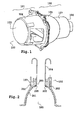
- a projector 100 of the elliptical type that is to say involving a projection lens 103, has two parts main parts: a first part 101 is constituted by the lens 103 and by a lens holder 104.
- a second portion 102 is constituted by a reflecting device of the state of the art.
- Reflector device 102 is consisting of a single piece fulfilling both the reflector function at the level of a rounded portion 105, and of a lamp holder at a rear end 106.
- the reflector 105 has the function of reflecting light signals produced by a light source placed in the heart of the rounded part to produce a light beam meeting the requirements imposed by different standards.
- the lamp holder 106 has the function of keep the light source in an appropriate position within the reflector 105.
- the junction between the lamp holder 106 and the reflector 105 is ensured by a cylindrical element 107.
- the element cylindrical 107 is closed: its lateral part has no opening because to provide openings, the mold used to manufacture the device reflector should involve drawers and would be too complex and expensive to realize for the manufacture of this piece; the base (at the door lamp 106) and the top (at the level of the reflector 105) of the element cylindrical 107 are also, at least largely, plugged by different parts of the light source that is introduced into the reflector 105.
- the cylindrical element 107 is closed, especially at the level of of its lateral part poses a first problem: the reflector device 102 is not ventilated enough, and this can interfere with prolonged the light source when turned on; indeed, the increase of the temperature is very fast in the reflector device 102, which can go until the destruction of the light source.
- FIG. 2 A second problem encountered with the reflector devices of the state of the art is illustrated in Figure 2.
- a section vertical of the reflector device 102 is shown.
- An internal surface 201 of the reflector 105 is thus apparent.
- the cylindrical element comprises including an outer wall 202, which was visible in Figure 1, and a inner wall 203.
- the inner wall 203 also constitutes a cylinder closed.
- the device according to the invention answers the two main problems which have just been exposed.
- a reflector device which on the one hand ensures good ventilation of a light source placed in the reflecting device, and who else share facilitates the passage of the reflector device on production lines for coating an inner surface of the reflector with powder.
- One of the interests of the reflector device according to the invention is that it can still be manufactured with molds, without subsequent machining operations of castings which could damage the inner surface of the reflector, the molds used, which can always be of simple design, that is to say especially without the presence of molding drawers.
- a reflector device in which a reflector element and a lamp element are manufactured separately before being secured.
- the reflective element thus manufactured has a set of supports that are arranged in such a way that light source subsequently installed in the reflecting device may be ventilated satisfactorily.
- the lamp holder element is secured with the reflector element at the supports by means of centering pins and assembly rods.
- the invention therefore essentially relates to a reflector device for motor vehicle headlamp, the reflector device having a reflector element comprising an internal reflecting surface, a outer surface, and an opening on a back part of the element reflector for introducing a light source, characterized in that the reflector device comprises a lamp holder element secured to the element reflector by means of a set of supports, said supports being arranged so as to create an open space between the lamp holder element and the reflective element.
- at least one of said supports takes pressing on a base (311) of the reflector element (301), said base (311) being distinct from the outer surface (309) of the reflector element (301).
- Another object of the invention is a motor vehicle equipped with a reflector device including one of the features that have just been mentioned.
- Figure 3 shows a reflector device 300 according to the invention in vertical section, which is composed in particular of a reflector element 301 and a door element lamp 302.
- the lamp holder element 302 and the reflector element 301 respectively comprise a first opening 314 and a second opening 315 (visible in particular in Figure 6) provided to leave a passage intended for the installation of a light source.
- a first element 303, hatched in Figure 3 because it is located in the plane of section, and a second support member 304 are visible on this Fig.
- the support elements which will be referred to as the column, are of elongated shape, ie they have a length l clearly greater than their height h, which in a particular example are respectively of the order of 60 millimeters and 15 millimeters; the thickness e of these columns being of the order of 2 millimeters at a first end 307, said fixing end, and of the order of 5 millimeters at level of a second end 306, said molded end.
- the reflector device 300 comprises a third column 305, visible in FIG. 5.
- the third column 305 is not visible in Figure 3 because it is aligned with the second column 304, that is, the planes, called support planes, containing the surfaces constituting the height of each of these columns are merged.
- the first column 303 defines a plan containing a surface constituting its height, said plane being perpendicular to the support planes of the second column 304 and the third column 305.
- This arrangement of the columns constitutes an excellent key at the time of assembly of the reflector element 301 and the lamp holder element 302, a single assembly position being possible. However, it is possible to make others otherwise foolproofing of the assembly of the reflector element 301 and the lamp holder element 302.
- the arrangement of the support columns is such that it leaves appear an empty space 308 between these columns and between the door element 302 lamp and the reflector element 301.
- the cylindrical element 107 of the state of the art has disappeared and was replaced by a fastening system of the door element lamp 302 involving support columns.
- Such openings allow optimal ventilation of a light source introduced into the reflector device 300.
- the molded end 306 of each column is in the shape of a outer surface 309 of the reflector element 301, as shown in FIG. This makes it possible to distribute all the pressure forces, which could practice on the different columns, on a maximum surface of the reflective element, thus limiting the risk of deformation of a surface internal 310, said photometric surface, for reflecting the signals light produced by the light source installed in the device reflector.
- the molded end 306 at least one support column ends at a surface 311 used to attach a lens holder of the type of the one present at the The surface 311 is called the base of the reflector element 301. It does not constitute the back of the reflective inner surface 310. In illustrated example, this base 311 is disposed in an exit plane of the light beam out of the reflector device 301. Such an embodiment can further limit the mechanical constraints that could to damage the inner surface 310 of the reflector element 301.
- One or more support columns may also have one or more reinforcing elements.
- Such reinforcing elements are visible hatched in Figure 6: we see, on columns 303 and 304 an element central reinforcement 312, located approximately in the center of each column, and an inner reinforcing member 313, located near the openings 314 and 315 provided for introducing the light source.
- the reinforcement elements 312 and 313 result in protuberances on the support columns. They serve on the one hand to limit the constraints mechanical that could damage the inner surface 310 of the element reflector 301, and on the other hand to evacuate, by convection, part of the heat generated by the light source.
- the lamp holder element 302 is circular in shape and is capable of to receive in its thickness a ring-shaped element serving as a base to the light source, which is fixed, for example by a rotational movement, in the lamp holder element.
- the lamp holder element 302 and the reflector element 301 including the columns of support are made in separate molds. This method of manufacture of the reflector device according to the invention also makes it possible to realize these two elements in different materials.
- the reflector element 301 and the support columns are made of aluminum, the lamp holder element being made of an alloy of zinc and aluminum. Other metals, alloys or plastics can also be used in the realization of these parts, the element reflector may in particular be made of a material thermosetting or in a thermoplastic material.
- each of these ends comprises a positioning pin 316 of a light source which will be arranged in the lamp holder element 302 and a centering rod and 317.
- the positioning pin 316 ensures the correct positioning of the light source relative to the inner surface 310 of the reflector element 302.
- Each centering and holding rod 317 is intended to be introduced into a specific opening of the element lamp holder 302. The presence of the pawn is useful for the game between a support column and the lamp holder element is zero or virtually zero. of the specific openings are also provided in the lamp holder element 302 to receive each positioning pin 316.
- each centering and holding rod 317 and each positioning pin 316 are introduced into their respective aperture, a peel operation is performed.
- This operation consists of deform the end of each centering and holding rod 317, to come crush it on 318 holding elements provided around each opening for receiving a holding rod.
- Such a mechanism of fastening the lamp holder element 302 and the reflector element 301 make the association of these two pieces final. A detachment of these two pieces would necessarily result in the deterioration of at least one of the elements.
- Another advantage inherent in the structure of the reflector device according to the invention is that the hooks 204, present on the production lines, can now grip at the openings 308, and thus no longer to damage the inner surface 310 of the reflector element 301.
- the reflector with lamp holder according to the invention is very advantageous, especially because the studs on which the lamp holder is the top of the backrest preferably rest on the front of the reflector, there is therefore no (less) deformation of it during assembly.
- the reflector and the lamp holder are preferably metallic (aluminum or alloy aluminum). This highly conductive material associated with the type of already described pads (“radiator fins”) promotes evacuation of the satisfactory heat.
Landscapes
- Engineering & Computer Science (AREA)
- General Engineering & Computer Science (AREA)
- Non-Portable Lighting Devices Or Systems Thereof (AREA)
- Lighting Device Outwards From Vehicle And Optical Signal (AREA)
Abstract
Description
- des feux de position, d'intensité et de portée faible ;
- des feux de croisement, ou codes, d'intensité plus forte et de portée sur la route avoisinant 70 mètres, qui sont utilisés essentiellement la nuit et dont la répartition du faisceau lumineux est telle qu'elle permet de ne pas éblouir le conducteur d'un véhicule croisé ;
- des feux de route longue portée, et des feux de complément de type longue portée, dont la zone de vision sur la route avoisine 200 mètres, et qui doivent être éteints lorsque l'on croise un autre véhicule afin de ne pas éblouir son conducteur ;
- des feux anti-brouillard.
- l'élément réflecteur et l'ensemble de supports sont réalisés dans une même matière et lors d'une même opération de moulage.
- l'ensemble de supports est constitué d'au moins deux colonnes de support, par exemple trois colonnes de support.
- les colonnes de support ont une première extrémité destinée à maintenir l'élément porte lampe, et une deuxième extrémité épousant au moins en partie la forme de la surface externe de l'élément réflecteur.
- la deuxième extrémité d'au moins une colonne de support est prolongée pour prendre appui sur une base de l'élément réflecteur, ladite base étant distincte de la surface externe de l'élément réflecteur.
- la base de l'élément réflecteur est contenue dans un plan de sortie du dispositif réflecteur.
- au moins une colonne de support comporte un élément de renfort central.
- au moins une colonne de support comporte un élément de renfort intérieur.
- une première colonne et une deuxième colonne ont une forme allongée, définissant respectivement un premier plan de support et un deuxième plan de support de l'élément porte lampe, le premier plan de support et le deuxième plan de support étant confondus.
- une troisième colonne a une forme allongée, définissant un troisième plan de support de l'élément porte lampe, le troisième plan de support étant perpendiculaire au premier plan de support.
- la solidarisation de l'élément porte lampe et de l'élément réflecteur est définitive.
- la première extrémité de chaque support comporte un pion de positionnement destiné à être inséré dans une ouverture prévue à cet effet dans l'élément porte lampe.
- la première extrémité de chaque support comporte une tige de centrage et de maintien destinée à être insérée dans une ouverture prévue à cet effet dans l'élément porte lampe, le maintien de l'élément porte lampe étant assuré par une opération de bouterollage de la tige de centrage et de maintien sur l'élément porte lampe.
- l'élément réflecteur et l'ensemble de support sont réalisés en aluminium ou dans un alliage à base d'aluminium. (l'élément réflecteur, notamment, peut aussi être en matériau plastique, en thermoplastique ou en thermodurcissable).
- l'élément porte lampe est réalisé dans un alliage de zinc et d'aluminium ou dans un alliage à base de zinc et d'aluminium
- à la figure 1, déjà décrite, une vue en perspective d'un dispositif projecteur de l'état de la technique;
- à la figure 2, déjà décrite, une vue en coupe d'un dispositif réflecteur de l'état de la technique;
- à la figure 3, une section verticale d'un dispositif réflecteur selon l'invention;
- à la figure 4, un détail d'un moyen de fixation entre deux éléments du dispositif réflecteur selon l'invention;
- à la figure 5, une vue arrière du dispositif réflecteur selon l'invention;
- à la figure 6, une vue en perspective du dispositif réflecteur selon l'invention.
Claims (17)
- Dispositif réflecteur (300) pour projecteur de véhicule automobile, le dispositif réflecteur comportant un élément réflecteur (301) comprenant une surface réfléchissante interne (310), une surface externe (309), et une ouverture (315) sur une partie arrière de l'élément réflecteur (301) pour introduire une source lumineuse caractérisé en ce que le dispositif réflecteur (300) comporte un élément porte lampe (302) solidarisé à l'élément réflecteur (301) au moyen d'un ensemble de supports (303 ;304 ;305), lesdits supports (303 ;304 ;305) étant disposés de sorte à créer un espace ouvert (308) entre l'élément porte lampe (302) et l'élément réflecteur (301), au moins un desdits supports prenant appui sur une base (311) de l'élément réflecteur (301), ladite base (311) étant distincte de la surface externe (309) de l'élément réflecteur (301).
- Dispositif réflecteur (300) selon la revendication précédente caractérisé en ce que l'élément réflecteur (301) et l'ensemble de supports (303 ;304 ;305) sont réalisés dans une même matière et lors d'une même opération de moulage.
- Dispositif réflecteur (300) selon l'une au moins des revendications précédentes caractérisé en ce que l'ensemble de supports est constitué d'au moins deux colonnes de support.
- Dispositif réflecteur (300) selon l'une au moins des revendications précédentes caractérisé en ce que l'ensemble de supports (303 ;304 ;305) est constitué de trois colonnes de support.
- Dispositif réflecteur (300) selon l'une au moins des revendications 3 ou 4 caractérisé en ce que les colonnes de support (303 ;304 ;305) ont une première extrémité (307) destinée à maintenir l'élément porte lampe (302), et une deuxième extrémité (306) épousant au moins en partie la forme de la surface externe (309) de l'élément réflecteur (301).
- Dispositif réflecteur (300) selon la revendication précédente caractérisé en ce que la deuxième extrémité (306) d'au moins une colonne de support (303 ;304 ;305) est prolongée pour prendre appui sur une base (311) de l'élément réflecteur (301), ladite base (311) étant distincte de la surface externe (309) de l'élément réflecteur (301).
- Dispositif réflecteur (300) selon la revendication précédente caractérisé en ce que la base (311) de l'élément réflecteur (301) est contenue dans un plan de sortie du dispositif réflecteur (300).
- Dispositif réflecteur (300) selon l'une au moins des revendications 3 à 7 caractérisé en ce qu'au moins une colonne de support (303 ;304 ;305) comporte un élément de renfort central (312).
- Dispositif réflecteur (300) selon l'une au moins des revendications 3 à 8 caractérisé en ce qu'au moins une colonne de support (303 ;304 ;305) comporte un élément de renfort intérieur (313).
- Dispositif réflecteur (300) selon l'une au moins des revendications 3 à 9 caractérisé en ce qu'une première colonne (304) et une deuxième colonne (305) ont une forme allongée, définissant respectivement un premier plan de support et un deuxième plan de support de l'élément porte lampe (302), le premier plan de support et le deuxième plan de support étant confondus.
- Dispositif réflecteur (300) selon la revendication précédente caractérisé en ce qu'une troisième colonne (303) a une forme allongée, définissant un troisième plan de support de l'élément porte lampe (302), le troisième plan de support étant perpendiculaire au premier plan de support.
- Dispositif réflecteur (300) selon l'une au moins des revendications précédentes caractérisé en ce que la solidarisation de l'élément porte lampe (302) et de l'élément réflecteur (301) est définitive.
- Dispositif réflecteur (300) selon l'une au moins des revendications 5 à 12 caractérisé en ce que la première extrémité (307) de chaque colonne de support (303 ;304 ;305) comporte un pion de positionnement (316) destiné à être inséré dans une ouverture prévue à cet effet dans l'élément porte lampe (302).
- Dispositif réflecteur (300) selon l'une au moins des revendications 5 à 13 caractérisé en ce que la première extrémité (307) de chaque colonne de support (303 ;304 ;305) comporte une tige de centrage et de maintien (317) destinée à être insérée dans une ouverture prévue à cet effet dans l'élément porte lampe (302), le maintien de l'élément porte lampe (302) étant assuré par une opération de bouterollage de la tige de centrage et de maintien (317) sur l'élément porte lampe (302).
- Dispositif réflecteur (300) selon l'une au moins des revendications précédentes caractérisé en ce que l'élément réflecteur (301) et l'ensemble de support (303 ;304 ;305) sont réalisés en aluminium ou dans un alliage à base d'aluminium.
- Dispositif réflecteur (300) selon l'une au moins des revendications précédentes caractérisé en ce que l'élément porte lampe (302) est réalisé dans un alliage de zinc et d'aluminium, ou dans un alliage à base de zinc et d'aluminium.
- Véhicule automobile équipé d'un dispositif réflecteur (300) selon l'une au moins des revendications précédentes.
Applications Claiming Priority (2)
| Application Number | Priority Date | Filing Date | Title |
|---|---|---|---|
| FR0210126A FR2843442B1 (fr) | 2002-08-08 | 2002-08-08 | Dispositif reflecteur pour projecteur de vehicule automobile |
| FR0210126 | 2002-08-08 |
Publications (2)
| Publication Number | Publication Date |
|---|---|
| EP1388710A1 true EP1388710A1 (fr) | 2004-02-11 |
| EP1388710B1 EP1388710B1 (fr) | 2006-05-24 |
Family
ID=30129727
Family Applications (1)
| Application Number | Title | Priority Date | Filing Date |
|---|---|---|---|
| EP03292000A Expired - Lifetime EP1388710B1 (fr) | 2002-08-08 | 2003-07-21 | Dispositif réflecteur pour projecteur de véhicule automobile |
Country Status (9)
| Country | Link |
|---|---|
| US (1) | US6863426B2 (fr) |
| EP (1) | EP1388710B1 (fr) |
| JP (1) | JP2004071575A (fr) |
| KR (1) | KR20040014331A (fr) |
| AT (1) | ATE327471T1 (fr) |
| BR (1) | BR0302748B1 (fr) |
| DE (1) | DE60305391T2 (fr) |
| ES (1) | ES2265094T3 (fr) |
| FR (1) | FR2843442B1 (fr) |
Families Citing this family (2)
| Publication number | Priority date | Publication date | Assignee | Title |
|---|---|---|---|---|
| CN100427337C (zh) * | 2004-08-05 | 2008-10-22 | 齐俊曌 | 车体轮廓照明灯 |
| EP2053628A1 (fr) * | 2007-10-26 | 2009-04-29 | Koninklijke Philips Electronics N.V. | Unité de lampe à culot et réflecteur |
Citations (5)
| Publication number | Priority date | Publication date | Assignee | Title |
|---|---|---|---|---|
| FR2487040A1 (fr) * | 1980-02-29 | 1982-01-22 | Marchal Equip Auto | Projecteur d'eclairage notamment pour vehicules automobiles |
| DE3425291A1 (de) * | 1984-07-10 | 1986-01-16 | Robert Bosch Gmbh, 7000 Stuttgart | Scheinwerfer fuer fahrzeuge, insbesondere fuer kraftfahrzeuge |
| EP0347065A2 (fr) * | 1988-06-17 | 1989-12-20 | Mag Instrument Inc. | Ecran de chaleur |
| US5032966A (en) * | 1989-05-02 | 1991-07-16 | Nafa Light Kurt Maurer, Inhaberin Frau M. Maurer-Werren | Bulb and reflector assembly |
| EP1043544A2 (fr) * | 1999-04-07 | 2000-10-11 | Zizala Lichtsysteme GmbH | Projecteur pour véhicule |
Family Cites Families (4)
| Publication number | Priority date | Publication date | Assignee | Title |
|---|---|---|---|---|
| US5113320A (en) * | 1990-08-16 | 1992-05-12 | Robart Enterprises, Inc. | Spherically adjustable headlamp mounting system |
| JP2559908B2 (ja) * | 1991-02-08 | 1996-12-04 | 株式会社小糸製作所 | 投射型自動車用ヘッドランプ |
| JP2507834B2 (ja) * | 1991-02-08 | 1996-06-19 | 株式会社小糸製作所 | 投射型自動車用ヘッドランプ |
| JP2610088B2 (ja) * | 1993-03-08 | 1997-05-14 | 株式会社小糸製作所 | 補助ランプ内蔵自動車用ヘッドランプ |
-
2002
- 2002-08-08 FR FR0210126A patent/FR2843442B1/fr not_active Expired - Fee Related
-
2003
- 2003-07-21 AT AT03292000T patent/ATE327471T1/de not_active IP Right Cessation
- 2003-07-21 DE DE60305391T patent/DE60305391T2/de not_active Expired - Lifetime
- 2003-07-21 EP EP03292000A patent/EP1388710B1/fr not_active Expired - Lifetime
- 2003-07-21 ES ES03292000T patent/ES2265094T3/es not_active Expired - Lifetime
- 2003-08-06 US US10/635,286 patent/US6863426B2/en not_active Expired - Lifetime
- 2003-08-07 BR BRPI0302748-1B1A patent/BR0302748B1/pt not_active IP Right Cessation
- 2003-08-07 KR KR1020030054687A patent/KR20040014331A/ko not_active Withdrawn
- 2003-08-08 JP JP2003290147A patent/JP2004071575A/ja active Pending
Patent Citations (5)
| Publication number | Priority date | Publication date | Assignee | Title |
|---|---|---|---|---|
| FR2487040A1 (fr) * | 1980-02-29 | 1982-01-22 | Marchal Equip Auto | Projecteur d'eclairage notamment pour vehicules automobiles |
| DE3425291A1 (de) * | 1984-07-10 | 1986-01-16 | Robert Bosch Gmbh, 7000 Stuttgart | Scheinwerfer fuer fahrzeuge, insbesondere fuer kraftfahrzeuge |
| EP0347065A2 (fr) * | 1988-06-17 | 1989-12-20 | Mag Instrument Inc. | Ecran de chaleur |
| US5032966A (en) * | 1989-05-02 | 1991-07-16 | Nafa Light Kurt Maurer, Inhaberin Frau M. Maurer-Werren | Bulb and reflector assembly |
| EP1043544A2 (fr) * | 1999-04-07 | 2000-10-11 | Zizala Lichtsysteme GmbH | Projecteur pour véhicule |
Also Published As
| Publication number | Publication date |
|---|---|
| DE60305391T2 (de) | 2007-03-08 |
| EP1388710B1 (fr) | 2006-05-24 |
| BR0302748B1 (pt) | 2014-04-08 |
| US6863426B2 (en) | 2005-03-08 |
| US20040027835A1 (en) | 2004-02-12 |
| FR2843442B1 (fr) | 2004-11-26 |
| FR2843442A1 (fr) | 2004-02-13 |
| JP2004071575A (ja) | 2004-03-04 |
| BR0302748A (pt) | 2004-08-24 |
| ES2265094T3 (es) | 2007-02-01 |
| ATE327471T1 (de) | 2006-06-15 |
| DE60305391D1 (de) | 2006-06-29 |
| KR20040014331A (ko) | 2004-02-14 |
Similar Documents
| Publication | Publication Date | Title |
|---|---|---|
| EP2598793B1 (fr) | Module optique de dispositif d'eclairage et/ou de signalisation d'un vehicule automobile | |
| FR2863343A1 (fr) | Phare a plusieurs elements photoemissifs | |
| EP2598797B1 (fr) | Module optique de dispositif d'eclairage et/ou de signalisation de vehicule automobile | |
| EP1288562A1 (fr) | Dispositif d'éclairage ou de signalisation pour véhicule automobile | |
| FR2878938A1 (fr) | Module d'eclairage pour projecteur de vehicule automobile | |
| EP3201523B1 (fr) | Véhicule automobile avec une calandre et un feu de signalisation | |
| FR3083514A1 (fr) | Systeme de retenue des bords d’un element de carrosserie au niveau de l’ouverture d’implantation d’un systeme d’eclairage et/ou de signalisation | |
| FR2742393A1 (fr) | Feu de signalisation a encombrement axial reduit, notamment feu stop sureleve | |
| FR3046579A1 (fr) | Bloc optique comprenant un feu de signalisation dote d’un guide de lumiere plat saillant de sa glace exterieure | |
| EP3212992B1 (fr) | Module optique compact pour véhicule | |
| EP1388710B1 (fr) | Dispositif réflecteur pour projecteur de véhicule automobile | |
| EP2216587A1 (fr) | Feu pour véhicule avec système entretoise pour guide de lumière | |
| EP2926049B1 (fr) | Dispositif de signalisation pour véhicule avec effet tridimensionnel | |
| EP3453955B1 (fr) | Module lumineux pour l'eclairage et/ou la signalisation d'un vehicule automobile | |
| FR2537249A1 (fr) | Projecteur a faisceau coupe a reflecteur elliptique pour vehicule automobile | |
| EP1488954A1 (fr) | Système d'éclairage ou de signalisation pour véhicule automobile | |
| FR2964723A1 (fr) | Module optique de dispositif d'eclairage et / ou de signalisation d'un vehicule automobile | |
| EP0984222A1 (fr) | Projecteur de véhicule automobile à lampe transversale équipé de moyens perfectionnés de la lampe | |
| FR3145594A1 (fr) | Dispositif d’eclairage avant pour vehicule terrestre | |
| FR3062194A1 (fr) | Unite de lampe | |
| EP1544538B1 (fr) | Dispositif projecteur avec porte-lampe | |
| FR3115856A1 (fr) | Fixation d’une lentille de module lumineux de vehicule | |
| EP1655537B1 (fr) | Dispositif projecteur avec élément d'occultation à système de fixation intégré et procédé de fixation d'un élément d'occultation dans un dispositif projecteur | |
| EP1739345B1 (fr) | Module optique pour véhicule automobile | |
| EP2379941A1 (fr) | Bloc optique de véhicule automobile à plaque de séparation fonctionnelle solidarisée à sa paroi principale par plaquage sous contrainte élastique |
Legal Events
| Date | Code | Title | Description |
|---|---|---|---|
| PUAI | Public reference made under article 153(3) epc to a published international application that has entered the european phase |
Free format text: ORIGINAL CODE: 0009012 |
|
| AK | Designated contracting states |
Kind code of ref document: A1 Designated state(s): AT BE BG CH CY CZ DE DK EE ES FI FR GB GR HU IE IT LI LU MC NL PT RO SE SI SK TR |
|
| AX | Request for extension of the european patent |
Extension state: AL LT LV MK |
|
| 17P | Request for examination filed |
Effective date: 20040805 |
|
| AKX | Designation fees paid |
Designated state(s): AT BE BG CH CY CZ DE DK EE ES FI FR GB GR HU IE IT LI LU MC NL PT RO SE SI SK TR |
|
| R17P | Request for examination filed (corrected) |
Effective date: 20040728 |
|
| 17Q | First examination report despatched |
Effective date: 20050210 |
|
| GRAP | Despatch of communication of intention to grant a patent |
Free format text: ORIGINAL CODE: EPIDOSNIGR1 |
|
| GRAS | Grant fee paid |
Free format text: ORIGINAL CODE: EPIDOSNIGR3 |
|
| GRAA | (expected) grant |
Free format text: ORIGINAL CODE: 0009210 |
|
| AK | Designated contracting states |
Kind code of ref document: B1 Designated state(s): AT BE BG CH CY CZ DE DK EE ES FI FR GB GR HU IE IT LI LU MC NL PT RO SE SI SK TR |
|
| PG25 | Lapsed in a contracting state [announced via postgrant information from national office to epo] |
Ref country code: SI Free format text: LAPSE BECAUSE OF FAILURE TO SUBMIT A TRANSLATION OF THE DESCRIPTION OR TO PAY THE FEE WITHIN THE PRESCRIBED TIME-LIMIT Effective date: 20060524 Ref country code: GB Free format text: LAPSE BECAUSE OF FAILURE TO SUBMIT A TRANSLATION OF THE DESCRIPTION OR TO PAY THE FEE WITHIN THE PRESCRIBED TIME-LIMIT Effective date: 20060524 Ref country code: NL Free format text: LAPSE BECAUSE OF FAILURE TO SUBMIT A TRANSLATION OF THE DESCRIPTION OR TO PAY THE FEE WITHIN THE PRESCRIBED TIME-LIMIT Effective date: 20060524 Ref country code: IE Free format text: LAPSE BECAUSE OF FAILURE TO SUBMIT A TRANSLATION OF THE DESCRIPTION OR TO PAY THE FEE WITHIN THE PRESCRIBED TIME-LIMIT Effective date: 20060524 Ref country code: FI Free format text: LAPSE BECAUSE OF FAILURE TO SUBMIT A TRANSLATION OF THE DESCRIPTION OR TO PAY THE FEE WITHIN THE PRESCRIBED TIME-LIMIT Effective date: 20060524 Ref country code: AT Free format text: LAPSE BECAUSE OF FAILURE TO SUBMIT A TRANSLATION OF THE DESCRIPTION OR TO PAY THE FEE WITHIN THE PRESCRIBED TIME-LIMIT Effective date: 20060524 Ref country code: RO Free format text: LAPSE BECAUSE OF FAILURE TO SUBMIT A TRANSLATION OF THE DESCRIPTION OR TO PAY THE FEE WITHIN THE PRESCRIBED TIME-LIMIT Effective date: 20060524 |
|
| REG | Reference to a national code |
Ref country code: GB Ref legal event code: FG4D Free format text: NOT ENGLISH |
|
| REG | Reference to a national code |
Ref country code: CH Ref legal event code: EP |
|
| REG | Reference to a national code |
Ref country code: IE Ref legal event code: FG4D Free format text: LANGUAGE OF EP DOCUMENT: FRENCH |
|
| REF | Corresponds to: |
Ref document number: 60305391 Country of ref document: DE Date of ref document: 20060629 Kind code of ref document: P |
|
| PG25 | Lapsed in a contracting state [announced via postgrant information from national office to epo] |
Ref country code: SK Free format text: LAPSE BECAUSE OF NON-PAYMENT OF DUE FEES Effective date: 20060721 |
|
| PG25 | Lapsed in a contracting state [announced via postgrant information from national office to epo] |
Ref country code: MC Free format text: LAPSE BECAUSE OF NON-PAYMENT OF DUE FEES Effective date: 20060731 Ref country code: BE Free format text: LAPSE BECAUSE OF NON-PAYMENT OF DUE FEES Effective date: 20060731 |
|
| PG25 | Lapsed in a contracting state [announced via postgrant information from national office to epo] |
Ref country code: DK Free format text: LAPSE BECAUSE OF FAILURE TO SUBMIT A TRANSLATION OF THE DESCRIPTION OR TO PAY THE FEE WITHIN THE PRESCRIBED TIME-LIMIT Effective date: 20060824 |
|
| REG | Reference to a national code |
Ref country code: SE Ref legal event code: TRGR |
|
| PG25 | Lapsed in a contracting state [announced via postgrant information from national office to epo] |
Ref country code: PT Free format text: LAPSE BECAUSE OF FAILURE TO SUBMIT A TRANSLATION OF THE DESCRIPTION OR TO PAY THE FEE WITHIN THE PRESCRIBED TIME-LIMIT Effective date: 20061024 |
|
| NLV1 | Nl: lapsed or annulled due to failure to fulfill the requirements of art. 29p and 29m of the patents act | ||
| GBV | Gb: ep patent (uk) treated as always having been void in accordance with gb section 77(7)/1977 [no translation filed] |
Effective date: 20060524 |
|
| REG | Reference to a national code |
Ref country code: IE Ref legal event code: FD4D |
|
| REG | Reference to a national code |
Ref country code: ES Ref legal event code: FG2A Ref document number: 2265094 Country of ref document: ES Kind code of ref document: T3 |
|
| PLBE | No opposition filed within time limit |
Free format text: ORIGINAL CODE: 0009261 |
|
| STAA | Information on the status of an ep patent application or granted ep patent |
Free format text: STATUS: NO OPPOSITION FILED WITHIN TIME LIMIT |
|
| 26N | No opposition filed |
Effective date: 20070227 |
|
| REG | Reference to a national code |
Ref country code: FR Ref legal event code: ST Effective date: 20070330 |
|
| BERE | Be: lapsed |
Owner name: VALEO VISION Effective date: 20060731 |
|
| REG | Reference to a national code |
Ref country code: CH Ref legal event code: PL |
|
| PG25 | Lapsed in a contracting state [announced via postgrant information from national office to epo] |
Ref country code: FR Free format text: LAPSE BECAUSE OF NON-PAYMENT OF DUE FEES Effective date: 20060731 Ref country code: LI Free format text: LAPSE BECAUSE OF NON-PAYMENT OF DUE FEES Effective date: 20070731 Ref country code: CH Free format text: LAPSE BECAUSE OF NON-PAYMENT OF DUE FEES Effective date: 20070731 Ref country code: GR Free format text: LAPSE BECAUSE OF FAILURE TO SUBMIT A TRANSLATION OF THE DESCRIPTION OR TO PAY THE FEE WITHIN THE PRESCRIBED TIME-LIMIT Effective date: 20060825 |
|
| PG25 | Lapsed in a contracting state [announced via postgrant information from national office to epo] |
Ref country code: EE Free format text: LAPSE BECAUSE OF FAILURE TO SUBMIT A TRANSLATION OF THE DESCRIPTION OR TO PAY THE FEE WITHIN THE PRESCRIBED TIME-LIMIT Effective date: 20060524 Ref country code: BG Free format text: LAPSE BECAUSE OF FAILURE TO SUBMIT A TRANSLATION OF THE DESCRIPTION OR TO PAY THE FEE WITHIN THE PRESCRIBED TIME-LIMIT Effective date: 20060824 |
|
| PG25 | Lapsed in a contracting state [announced via postgrant information from national office to epo] |
Ref country code: TR Free format text: LAPSE BECAUSE OF FAILURE TO SUBMIT A TRANSLATION OF THE DESCRIPTION OR TO PAY THE FEE WITHIN THE PRESCRIBED TIME-LIMIT Effective date: 20060524 Ref country code: HU Free format text: LAPSE BECAUSE OF FAILURE TO SUBMIT A TRANSLATION OF THE DESCRIPTION OR TO PAY THE FEE WITHIN THE PRESCRIBED TIME-LIMIT Effective date: 20061125 Ref country code: LU Free format text: LAPSE BECAUSE OF NON-PAYMENT OF DUE FEES Effective date: 20060721 |
|
| PG25 | Lapsed in a contracting state [announced via postgrant information from national office to epo] |
Ref country code: CY Free format text: LAPSE BECAUSE OF FAILURE TO SUBMIT A TRANSLATION OF THE DESCRIPTION OR TO PAY THE FEE WITHIN THE PRESCRIBED TIME-LIMIT Effective date: 20060524 |
|
| PGFP | Annual fee paid to national office [announced via postgrant information from national office to epo] |
Ref country code: SE Payment date: 20170719 Year of fee payment: 15 |
|
| PG25 | Lapsed in a contracting state [announced via postgrant information from national office to epo] |
Ref country code: SE Free format text: LAPSE BECAUSE OF NON-PAYMENT OF DUE FEES Effective date: 20180722 |
|
| PGFP | Annual fee paid to national office [announced via postgrant information from national office to epo] |
Ref country code: CZ Payment date: 20190620 Year of fee payment: 17 |
|
| PGFP | Annual fee paid to national office [announced via postgrant information from national office to epo] |
Ref country code: DE Payment date: 20190711 Year of fee payment: 17 Ref country code: ES Payment date: 20190809 Year of fee payment: 17 Ref country code: IT Payment date: 20190718 Year of fee payment: 17 |
|
| REG | Reference to a national code |
Ref country code: DE Ref legal event code: R119 Ref document number: 60305391 Country of ref document: DE |
|
| PG25 | Lapsed in a contracting state [announced via postgrant information from national office to epo] |
Ref country code: CZ Free format text: LAPSE BECAUSE OF NON-PAYMENT OF DUE FEES Effective date: 20200721 |
|
| PG25 | Lapsed in a contracting state [announced via postgrant information from national office to epo] |
Ref country code: DE Free format text: LAPSE BECAUSE OF NON-PAYMENT OF DUE FEES Effective date: 20210202 |
|
| REG | Reference to a national code |
Ref country code: ES Ref legal event code: FD2A Effective date: 20211202 |
|
| PG25 | Lapsed in a contracting state [announced via postgrant information from national office to epo] |
Ref country code: ES Free format text: LAPSE BECAUSE OF NON-PAYMENT OF DUE FEES Effective date: 20200722 |
|
| PG25 | Lapsed in a contracting state [announced via postgrant information from national office to epo] |
Ref country code: IT Free format text: LAPSE BECAUSE OF NON-PAYMENT OF DUE FEES Effective date: 20200721 |