EP1387720B1 - Reaktor für gas/flüssig- oder gas/flüssig/fest-reaktionen - Google Patents
Reaktor für gas/flüssig- oder gas/flüssig/fest-reaktionen Download PDFInfo
- Publication number
- EP1387720B1 EP1387720B1 EP02740529A EP02740529A EP1387720B1 EP 1387720 B1 EP1387720 B1 EP 1387720B1 EP 02740529 A EP02740529 A EP 02740529A EP 02740529 A EP02740529 A EP 02740529A EP 1387720 B1 EP1387720 B1 EP 1387720B1
- Authority
- EP
- European Patent Office
- Prior art keywords
- gas
- liquid
- chamber
- reactor
- gas distributor
- Prior art date
- Legal status (The legal status is an assumption and is not a legal conclusion. Google has not performed a legal analysis and makes no representation as to the accuracy of the status listed.)
- Expired - Lifetime
Links
- 239000007788 liquid Substances 0.000 title claims abstract description 116
- 238000006243 chemical reaction Methods 0.000 title claims abstract description 39
- 239000007787 solid Substances 0.000 title claims abstract description 16
- 239000012263 liquid product Substances 0.000 claims abstract description 4
- 239000003054 catalyst Substances 0.000 claims description 20
- 238000012856 packing Methods 0.000 claims description 11
- 230000032050 esterification Effects 0.000 claims description 6
- 238000005886 esterification reaction Methods 0.000 claims description 6
- 229920000909 polytetrahydrofuran Polymers 0.000 claims description 6
- 238000005809 transesterification reaction Methods 0.000 claims description 5
- 150000001298 alcohols Chemical class 0.000 claims description 4
- 238000000034 method Methods 0.000 claims description 4
- 230000008569 process Effects 0.000 claims description 4
- 239000000376 reactant Substances 0.000 claims description 4
- 239000011949 solid catalyst Substances 0.000 claims description 4
- NWUYHJFMYQTDRP-UHFFFAOYSA-N 1,2-bis(ethenyl)benzene;1-ethenyl-2-ethylbenzene;styrene Chemical compound C=CC1=CC=CC=C1.CCC1=CC=CC=C1C=C.C=CC1=CC=CC=C1C=C NWUYHJFMYQTDRP-UHFFFAOYSA-N 0.000 claims description 2
- 238000006266 etherification reaction Methods 0.000 claims description 2
- 238000005755 formation reaction Methods 0.000 claims description 2
- 150000002373 hemiacetals Chemical class 0.000 claims description 2
- 239000003456 ion exchange resin Substances 0.000 claims description 2
- 229920003303 ion-exchange polymer Polymers 0.000 claims description 2
- 230000008707 rearrangement Effects 0.000 claims description 2
- 238000011144 upstream manufacturing Methods 0.000 claims description 2
- XNGIFLGASWRNHJ-UHFFFAOYSA-N phthalic acid Chemical compound OC(=O)C1=CC=CC=C1C(O)=O XNGIFLGASWRNHJ-UHFFFAOYSA-N 0.000 claims 2
- 125000004423 acyloxy group Chemical group 0.000 claims 1
- 239000007789 gas Substances 0.000 description 114
- OKKJLVBELUTLKV-UHFFFAOYSA-N Methanol Chemical compound OC OKKJLVBELUTLKV-UHFFFAOYSA-N 0.000 description 21
- XBDQKXXYIPTUBI-UHFFFAOYSA-M Propionate Chemical compound CCC([O-])=O XBDQKXXYIPTUBI-UHFFFAOYSA-M 0.000 description 8
- KXKVLQRXCPHEJC-UHFFFAOYSA-N acetic acid trimethyl ester Natural products COC(C)=O KXKVLQRXCPHEJC-UHFFFAOYSA-N 0.000 description 8
- 238000002156 mixing Methods 0.000 description 8
- 239000012071 phase Substances 0.000 description 6
- 239000011541 reaction mixture Substances 0.000 description 5
- 239000007791 liquid phase Substances 0.000 description 4
- 239000002689 soil Substances 0.000 description 4
- 239000011261 inert gas Substances 0.000 description 3
- 239000000203 mixture Substances 0.000 description 3
- 239000000047 product Substances 0.000 description 3
- 238000000926 separation method Methods 0.000 description 3
- CURLTUGMZLYLDI-UHFFFAOYSA-N Carbon dioxide Chemical compound O=C=O CURLTUGMZLYLDI-UHFFFAOYSA-N 0.000 description 2
- WNLRTRBMVRJNCN-UHFFFAOYSA-N adipic acid Chemical compound OC(=O)CCCCC(O)=O WNLRTRBMVRJNCN-UHFFFAOYSA-N 0.000 description 2
- 230000004888 barrier function Effects 0.000 description 2
- 230000008901 benefit Effects 0.000 description 2
- 238000013461 design Methods 0.000 description 2
- 238000007598 dipping method Methods 0.000 description 2
- 230000000694 effects Effects 0.000 description 2
- 239000000945 filler Substances 0.000 description 2
- 239000007792 gaseous phase Substances 0.000 description 2
- 230000002706 hydrostatic effect Effects 0.000 description 2
- 230000000630 rising effect Effects 0.000 description 2
- 238000012546 transfer Methods 0.000 description 2
- SMZOUWXMTYCWNB-UHFFFAOYSA-N 2-(2-methoxy-5-methylphenyl)ethanamine Chemical compound COC1=CC=C(C)C=C1CCN SMZOUWXMTYCWNB-UHFFFAOYSA-N 0.000 description 1
- NIXOWILDQLNWCW-UHFFFAOYSA-N 2-Propenoic acid Natural products OC(=O)C=C NIXOWILDQLNWCW-UHFFFAOYSA-N 0.000 description 1
- LFQSCWFLJHTTHZ-UHFFFAOYSA-N Ethanol Chemical compound CCO LFQSCWFLJHTTHZ-UHFFFAOYSA-N 0.000 description 1
- LGRFSURHDFAFJT-UHFFFAOYSA-N Phthalic anhydride Natural products C1=CC=C2C(=O)OC(=O)C2=C1 LGRFSURHDFAFJT-UHFFFAOYSA-N 0.000 description 1
- GOOHAUXETOMSMM-UHFFFAOYSA-N Propylene oxide Chemical compound CC1CO1 GOOHAUXETOMSMM-UHFFFAOYSA-N 0.000 description 1
- 206010037660 Pyrexia Diseases 0.000 description 1
- 125000002252 acyl group Chemical group 0.000 description 1
- 239000001361 adipic acid Substances 0.000 description 1
- 235000011037 adipic acid Nutrition 0.000 description 1
- 230000015572 biosynthetic process Effects 0.000 description 1
- 238000009835 boiling Methods 0.000 description 1
- JHIWVOJDXOSYLW-UHFFFAOYSA-N butyl 2,2-difluorocyclopropane-1-carboxylate Chemical compound CCCCOC(=O)C1CC1(F)F JHIWVOJDXOSYLW-UHFFFAOYSA-N 0.000 description 1
- 239000001569 carbon dioxide Substances 0.000 description 1
- 229910002092 carbon dioxide Inorganic materials 0.000 description 1
- 230000008859 change Effects 0.000 description 1
- 239000012295 chemical reaction liquid Substances 0.000 description 1
- 239000007795 chemical reaction product Substances 0.000 description 1
- 239000006103 coloring component Substances 0.000 description 1
- 230000000052 comparative effect Effects 0.000 description 1
- 238000010924 continuous production Methods 0.000 description 1
- 238000000354 decomposition reaction Methods 0.000 description 1
- 230000003247 decreasing effect Effects 0.000 description 1
- 150000002148 esters Chemical class 0.000 description 1
- 230000002349 favourable effect Effects 0.000 description 1
- 239000002316 fumigant Substances 0.000 description 1
- 238000005984 hydrogenation reaction Methods 0.000 description 1
- 125000002887 hydroxy group Chemical group [H]O* 0.000 description 1
- 238000007654 immersion Methods 0.000 description 1
- 238000003780 insertion Methods 0.000 description 1
- 230000037431 insertion Effects 0.000 description 1
- 238000004519 manufacturing process Methods 0.000 description 1
- 239000002184 metal Substances 0.000 description 1
- 238000000465 moulding Methods 0.000 description 1
- 150000003021 phthalic acid derivatives Chemical class 0.000 description 1
- 239000004014 plasticizer Substances 0.000 description 1
- RUOJZAUFBMNUDX-UHFFFAOYSA-N propylene carbonate Chemical compound CC1COC(=O)O1 RUOJZAUFBMNUDX-UHFFFAOYSA-N 0.000 description 1
- 238000009790 rate-determining step (RDS) Methods 0.000 description 1
- 238000000066 reactive distillation Methods 0.000 description 1
- 239000007790 solid phase Substances 0.000 description 1
- 230000003068 static effect Effects 0.000 description 1
- 239000000126 substance Substances 0.000 description 1
- 230000007306 turnover Effects 0.000 description 1
- XLYOFNOQVPJJNP-UHFFFAOYSA-N water Substances O XLYOFNOQVPJJNP-UHFFFAOYSA-N 0.000 description 1
Images


Classifications
-
- B—PERFORMING OPERATIONS; TRANSPORTING
- B01—PHYSICAL OR CHEMICAL PROCESSES OR APPARATUS IN GENERAL
- B01J—CHEMICAL OR PHYSICAL PROCESSES, e.g. CATALYSIS OR COLLOID CHEMISTRY; THEIR RELEVANT APPARATUS
- B01J8/00—Chemical or physical processes in general, conducted in the presence of fluids and solid particles; Apparatus for such processes
- B01J8/18—Chemical or physical processes in general, conducted in the presence of fluids and solid particles; Apparatus for such processes with fluidised particles
- B01J8/20—Chemical or physical processes in general, conducted in the presence of fluids and solid particles; Apparatus for such processes with fluidised particles with liquid as a fluidising medium
- B01J8/22—Chemical or physical processes in general, conducted in the presence of fluids and solid particles; Apparatus for such processes with fluidised particles with liquid as a fluidising medium gas being introduced into the liquid
- B01J8/224—Chemical or physical processes in general, conducted in the presence of fluids and solid particles; Apparatus for such processes with fluidised particles with liquid as a fluidising medium gas being introduced into the liquid the particles being subject to a circulatory movement
- B01J8/226—Chemical or physical processes in general, conducted in the presence of fluids and solid particles; Apparatus for such processes with fluidised particles with liquid as a fluidising medium gas being introduced into the liquid the particles being subject to a circulatory movement internally, i.e. the particles rotate within the vessel
-
- B—PERFORMING OPERATIONS; TRANSPORTING
- B01—PHYSICAL OR CHEMICAL PROCESSES OR APPARATUS IN GENERAL
- B01J—CHEMICAL OR PHYSICAL PROCESSES, e.g. CATALYSIS OR COLLOID CHEMISTRY; THEIR RELEVANT APPARATUS
- B01J8/00—Chemical or physical processes in general, conducted in the presence of fluids and solid particles; Apparatus for such processes
- B01J8/18—Chemical or physical processes in general, conducted in the presence of fluids and solid particles; Apparatus for such processes with fluidised particles
- B01J8/20—Chemical or physical processes in general, conducted in the presence of fluids and solid particles; Apparatus for such processes with fluidised particles with liquid as a fluidising medium
- B01J8/22—Chemical or physical processes in general, conducted in the presence of fluids and solid particles; Apparatus for such processes with fluidised particles with liquid as a fluidising medium gas being introduced into the liquid
-
- B—PERFORMING OPERATIONS; TRANSPORTING
- B01—PHYSICAL OR CHEMICAL PROCESSES OR APPARATUS IN GENERAL
- B01D—SEPARATION
- B01D3/00—Distillation or related exchange processes in which liquids are contacted with gaseous media, e.g. stripping
- B01D3/009—Distillation or related exchange processes in which liquids are contacted with gaseous media, e.g. stripping in combination with chemical reactions
-
- B—PERFORMING OPERATIONS; TRANSPORTING
- B01—PHYSICAL OR CHEMICAL PROCESSES OR APPARATUS IN GENERAL
- B01D—SEPARATION
- B01D3/00—Distillation or related exchange processes in which liquids are contacted with gaseous media, e.g. stripping
- B01D3/14—Fractional distillation or use of a fractionation or rectification column
- B01D3/16—Fractionating columns in which vapour bubbles through liquid
- B01D3/18—Fractionating columns in which vapour bubbles through liquid with horizontal bubble plates
- B01D3/20—Bubble caps; Risers for vapour; Discharge pipes for liquid
-
- B—PERFORMING OPERATIONS; TRANSPORTING
- B01—PHYSICAL OR CHEMICAL PROCESSES OR APPARATUS IN GENERAL
- B01J—CHEMICAL OR PHYSICAL PROCESSES, e.g. CATALYSIS OR COLLOID CHEMISTRY; THEIR RELEVANT APPARATUS
- B01J47/00—Ion-exchange processes in general; Apparatus therefor
-
- B—PERFORMING OPERATIONS; TRANSPORTING
- B01—PHYSICAL OR CHEMICAL PROCESSES OR APPARATUS IN GENERAL
- B01J—CHEMICAL OR PHYSICAL PROCESSES, e.g. CATALYSIS OR COLLOID CHEMISTRY; THEIR RELEVANT APPARATUS
- B01J8/00—Chemical or physical processes in general, conducted in the presence of fluids and solid particles; Apparatus for such processes
- B01J8/18—Chemical or physical processes in general, conducted in the presence of fluids and solid particles; Apparatus for such processes with fluidised particles
- B01J8/1818—Feeding of the fluidising gas
-
- B—PERFORMING OPERATIONS; TRANSPORTING
- B01—PHYSICAL OR CHEMICAL PROCESSES OR APPARATUS IN GENERAL
- B01J—CHEMICAL OR PHYSICAL PROCESSES, e.g. CATALYSIS OR COLLOID CHEMISTRY; THEIR RELEVANT APPARATUS
- B01J8/00—Chemical or physical processes in general, conducted in the presence of fluids and solid particles; Apparatus for such processes
- B01J8/18—Chemical or physical processes in general, conducted in the presence of fluids and solid particles; Apparatus for such processes with fluidised particles
- B01J8/24—Chemical or physical processes in general, conducted in the presence of fluids and solid particles; Apparatus for such processes with fluidised particles according to "fluidised-bed" technique
- B01J8/34—Chemical or physical processes in general, conducted in the presence of fluids and solid particles; Apparatus for such processes with fluidised particles according to "fluidised-bed" technique with stationary packing material in the fluidised bed, e.g. bricks, wire rings, baffles
-
- B—PERFORMING OPERATIONS; TRANSPORTING
- B01—PHYSICAL OR CHEMICAL PROCESSES OR APPARATUS IN GENERAL
- B01J—CHEMICAL OR PHYSICAL PROCESSES, e.g. CATALYSIS OR COLLOID CHEMISTRY; THEIR RELEVANT APPARATUS
- B01J2219/00—Chemical, physical or physico-chemical processes in general; Their relevant apparatus
- B01J2219/32—Details relating to packing elements in the form of grids or built-up elements for forming a unit of module inside the apparatus for mass or heat transfer
- B01J2219/322—Basic shape of the elements
- B01J2219/32296—Honeycombs
-
- B—PERFORMING OPERATIONS; TRANSPORTING
- B01—PHYSICAL OR CHEMICAL PROCESSES OR APPARATUS IN GENERAL
- B01J—CHEMICAL OR PHYSICAL PROCESSES, e.g. CATALYSIS OR COLLOID CHEMISTRY; THEIR RELEVANT APPARATUS
- B01J2219/00—Chemical, physical or physico-chemical processes in general; Their relevant apparatus
- B01J2219/32—Details relating to packing elements in the form of grids or built-up elements for forming a unit of module inside the apparatus for mass or heat transfer
- B01J2219/324—Composition or microstructure of the elements
- B01J2219/32466—Composition or microstructure of the elements comprising catalytically active material
-
- Y—GENERAL TAGGING OF NEW TECHNOLOGICAL DEVELOPMENTS; GENERAL TAGGING OF CROSS-SECTIONAL TECHNOLOGIES SPANNING OVER SEVERAL SECTIONS OF THE IPC; TECHNICAL SUBJECTS COVERED BY FORMER USPC CROSS-REFERENCE ART COLLECTIONS [XRACs] AND DIGESTS
- Y02—TECHNOLOGIES OR APPLICATIONS FOR MITIGATION OR ADAPTATION AGAINST CLIMATE CHANGE
- Y02P—CLIMATE CHANGE MITIGATION TECHNOLOGIES IN THE PRODUCTION OR PROCESSING OF GOODS
- Y02P20/00—Technologies relating to chemical industry
- Y02P20/141—Feedstock
Definitions
- the invention relates to a reactor for gas / liquid or gas / liquid / solid reactions and its use.
- WO 90/08127 describes an esterification reactor having a plurality of trays, with the liquid reaction mixture flowing from top to bottom, wherein the gas is introduced into the liquid via a gas distributor below the liquid level on each tray and a baffle is arranged around the gas distributor, such that in the Liquid is induced an internal loop movement, which in the area of the inflating gas bubbles upwards and outside of the zone of the rising Gas bubbles is directed downwards.
- the esterification is carried out in the presence of a suspended solid catalyst.
- thermodynamic gas / liquid equilibrium Reason for a very good mix as well as after thorough mixing and reaction ensures a substantial separation of gaseous and liquid phase.
- the reactor should be able to be operated with the smallest possible pressure loss for the gas phase flowing from the bottom upwards.
- the solution is based on a reactor for gas / liquid or gas / liquid / solid reactions with vertically oriented longitudinal axis, with supply of a liquid or liquid / solid reactant stream in the upper region of the reactor and a gaseous stream in the lower region of the reactor.
- an apparatus which, without moving parts of the apparatus, by an air-lift circulation of the liquid, ensures excellent mixing in multiphase reactions and a nearly constant composition of the reaction mixture over the entire volume in each chamber, that is both on their Cross-section and in particular on the liquid level, with simultaneous simple separation between the liquid and gaseous phase after the reaction.
- the gas outlet from the gas distributor in the liquid space between the gas distributor and the or around the gas distributor around vertically arranged baffle or baffles the hydrostatic pressure in this liquid space is lowered compared to the non-fumigated liquid space, whereby a pressure gradient is created, which is converted into kinetic energy.
- This pressure gradient sets the air-lift circulation in the form of a flow in the gassed space, that is in the space between the gas distributor and the or around the gas distributor arranged around baffle (baffles) is directed upward in the area above the at the top of the baffle (s) and below the liquid level is deflected by the baffle (the baffles), the non-fumigated liquid space outside of the baffle (the baffles) flows from top to bottom and above the liquid-tight bottom of the chamber and below the lowermost end of the baffle (the baffles) is redirected again in a downward flow, whereby the loop movement is closed.
- the reactor according to the invention is an apparatus with vertically aligned longitudinal axis, i. an upstanding apparatus with supply of a liquid or liquid / solid reactant stream in its upper region and a gaseous stream - educt and / or inert gas - in its lower region, that is, with countercurrent flow of the liquid or liquid-solid and the gaseous stream. It is particularly suitable for continuous process control.
- the reactor is made up of several, in particular between 2 and 200 chambers, more preferably between 3 and 50 chambers arranged one above the other.
- the superimposed chambers can equally be designed as separate apparatus, with corresponding connections.
- the geometry of the reactor is often cylindrical, but other geometries, in particular a cuboid geometry, are also possible.
- each chamber is connected by a respective liquid overflow with the immediately underlying chamber.
- the liquid overflow can be formed for example in the form of a tube or a shaft and it can be arranged both inside and outside the reactor.
- the liquid overflows of two successive chambers each on opposite sides of the Reactor be arranged. From the bottom chamber, a liquid product stream is withdrawn via the liquid overflow.
- the gas space above the liquid level in each chamber is connected to the immediately above each arranged chamber by one or more gas supply pipes, each of which opens into a gas distributor with openings for the gas outlet below the liquid level.
- gas supply pipes there are basically no restrictions: it is equally possible to provide a single central gas supply pipe or else a plurality of gas supply pipes arranged distributed over the reactor cross section. It is also possible, instead of a single gas distributor per chamber several separate gas distributor, each with gas supply via one or more gas supply pipes to provide. In the gas distributor of the bottom chamber of the reactor, a gaseous stream is introduced via one or more gas supply pipes from outside the reactor.
- the reactor is designed such that in each chamber, the liquid overflow is lower than the upper end of the gas supply pipe (the gas supply pipes) for the gas supply.
- This embodiment ensures a static barrier which prevents liquid from draining through the gas supply pipe (s) into the underlying chamber.
- gas distributors which can be used in the present case, there are no fundamental restrictions: it is essential that the gas distributor discharge the gas supplied to it via the gas supply pipe or pipes from the gas space of the immediately underlying chamber below the liquid level of the chamber in which the gas distributor is arranged.
- the gas outlet should preferably be as uniform as possible.
- a gas distributor can be used in principle any commercial gassing, for example, gas distributor in the form of tubes which are equipped with outlet openings for the gas and, for example horizontally, that can be arranged in a plane parallel to the liquid-tight bottom of the chamber. It is also possible to provide annular gas distributors.
- the gas outlet openings are in the present case only through the gas, ie, flows through single-phase.
- the lower end of the gas distributor is preferably spaced from the bottom of the chamber, i. h., the gas distributor is not completely submerged in the liquid. Nevertheless, the air-lift effect ensures a very good mixing of the liquid.
- the openings of the gas distributor for the gas outlet are spaced from the bottom of the chamber, preferably by 40% to 90% of the liquid level in the chamber, measured from the bottom of the chamber to the liquid overflow.
- the openings of the gas distributor for the gas outlet are arranged below the upper end of the gas supply pipe.
- the gas distributor in the form of a closed top hood is formed with openings for the gas outlet in the lower part.
- the hood can be completely closed except for the passage openings for the gas supply pipe or pipes for the gas supply and the gas outlet openings in its lower part.
- the upper closed end of the hood may terminate below the liquid level, but may also extend beyond the liquid level into the gas space.
- the hood of the gas distributor can basically have any geometric shape; it is possible, for example, that it consists of several interconnected parts, the in cross section are preferably arranged in a cross shape and / or parallel or concentric or radial.
- the openings for the gas outlet are preferably formed in terms of number, cross section and distance from the liquid level in the chamber in such a way that the pressure drop of the gaseous stream in the gas distributor in the range of 0.1 to 50 mbar, preferably from 0.5 to 15 mbar, lies.
- the openings for the gas distributor are preferably arranged at the same height to each other.
- they can have any desired geometric shape, for example circular, triangular or slot-shaped.
- the center line of the openings is preferably at a distance of about 1 cm to 15 cm from the lower end of the hood.
- the arrangement of the openings at different heights may be advantageous for operation with two or more load ranges.
- the height of the openings for the gas outlet is selected as needed, depending on the specific reaction to be carried out in the reactor so that on the one hand sufficient mass transfer surface for the specific gas / liquid or gas / liquid / solid reaction is offered and on the other sufficient drive for the air-lift circulation of the liquid is provided.
- At least one vertical baffle is arranged around each gas distributor in the reactor according to the invention, the upper end of which ends below the liquid level in the chamber, is spaced from the bottom of the chamber and which gasses each chamber into one or more and separates one or more unfavorable spaces.
- the baffle may be formed in a preferred embodiment as a cylinder jacket-shaped insertion tube. Likewise, however, is also possible, for example, the shape of a simple flat sheet.
- the at least one baffle is spaced from the liquid level and from the bottom of the chamber, preferably such that there is substantially no throttling of the liquid flow through the baffle.
- the distances of the baffle or baffles to the liquid surface as well as to the bottom of the chamber are thus preferably set in such a way that the flow rate of the liquid does not change or only slightly during the deflection by the baffle.
- the liquid-tight bottoms and / or the gas distributor and / or the baffles are formed as heat exchanger plates.
- inserts are provided for receiving catalyst packings, with one or more vertical, preferably symmetrically arranged, laterally liquid-permeable drainage shafts, which are open at the top and closed down, and with liquid-permeable walls in the area of baffles. It is preferred to form the inserts in such a way that they make maximum use of the unfavorable spaces, ie fill them as completely as possible. In this case, it is preferable to design the expansion of the inserts in the vertical direction equal to or almost equal to the vertical extent of the guide plates.
- the inserts are preferably formed in such a way that they can be easily hung in the baffles and, if necessary, for example, for the purpose of changing the catalyst packing, removed.
- the drainage shafts have the function of distributing the liquid as evenly as possible over the catalyst filling in the transverse direction. They must be closed at the bottom in order to avoid a bypass flow of the liquid through the catalyst filling.
- the inserts have liquid-permeable walls in the area of the guide plates; Thus, the liquid, after having flowed through the catalyst filling, along the Move baffles in the unfavorable rooms downwards.
- the liquid-permeable walls can be designed, for example, as sieves or as perforated metal sheets, as well as the lateral walls of the drainage shafts.
- a solid catalyst in the form of catalyst-coated ordered packings, or as a catalyst-coated monolith may be introduced.
- an ion exchange resin may be introduced.
- the reactor according to the invention thus has the advantage that it ensures a very good mixing of the liquid and a reliable separation of the gas phase for gas / liquid or gas / liquid / solid reactions. Since it is only necessary for the drive of the air-lift circulation that the gas outlet from the gas distributor takes place below the liquid level in the chamber, wherein the height of the dipping with respect to the liquid level can generally vary within very wide limits, with the reactor according to the invention provided an apparatus in which diesstechniksverweilzeit and gas-side pressure loss are largely decoupled, especially when the dipping is low.
- the reactor is particularly suitable for performing gas / liquid or gas / liquid / solid reactions where not only the mass transfer surface is the rate limiting step. He is also suitable for continuous reactions with Reaction order of 1 or greater, which are to be brought to a high degree of conversion, for example, the reaction of propylene oxide with carbon dioxide to propylene carbonate and for hydrogenations, for example for Farbierehydrtechniken.
- the reactor according to the invention is particularly suitable for carrying out equilibrium reactions which are to be brought to a high degree of conversion, and in which a coproduct is removed as vapor continuously with inert gas or with one of the reactants from the reaction mixture to the reaction equilibrium in the desired direction move.
- Examples include esterifications, such as the esterification of phthalic or phthalic anhydride with alcohols to phthalic acid esters, which are preferably used as plasticizers, or the esterification of adipic acid or acrylic acid with alcohols to their esters. Characteristic of all these reactions is that the water formed in order to shift the reaction equilibrium is continuously removed with inert gas or preferably with alcohol vapor in countercurrent flow from the reaction mixture.
- transesterification reactions in particular the transesterification of polytetrahydrofuran with terminal acyl groups in the presence of lower alcohols, preferably from methanol to polytetrahydrofuran with terminal hydroxyl groups, etherifications, rearrangements, hydrolyses and hemiacetal formations.
- the reactor according to the invention can also be used advantageously in conjunction with an upstream single-phase reactor, in particular a tubular reactor, in order to substantially already reach the chemical equilibrium therein.
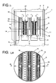
- Fig. 1 1 shows by way of example one of a plurality of longitudinally stacked chambers 4 of a reactor 1 with feed 2 of a liquid or liquid / solid educt stream in the upper region and a gaseous stream 3 in the lower region of the reactor 1, each having a bottom 5 per chamber 4, Liquid overflows 6, which are exemplarily shown inside the reactor 1, each having a gas space 7 above the liquid level in each chamber 4, which is exemplified by three Gaszutechnischsrohre8 with the respective overlying chamber 4 and in a gas distributor 9 in the form of a closed top hood 10 of three interconnected parts opens, with openings 11 for the gas outlet in the lower part.
- baffles 12 are arranged, which are each spaced from the liquid level and the bottom of the chamber 4 and the chamber 4 separates into a plurality of fumigated spaces 13 and a plurality of unfavorable spaces 14.
- the longitudinal section is in the in Figure 1A laid down at BB to simultaneously illustrate the arrangement of the gas supply pipes 8 and the gas distributor 9 or the three parts thereof.
- the gas flows into the gas distributor via the upper region of the conduit and exits from the same, in its lower region, out of the openings 11.
- Fig. 1a In the cross-sectional representation in Fig. 1a is the shape of the hood 10 of the gas distributor 9 illustrates, in this case exemplified as formed from cross-shaped and parallel parts.
- inserts 15 for receiving shown in the figure by cross-hatching catalyst filler provided.
- the inserts 15 have drainage shafts 16 which are open at the top and closed at the bottom, and through which the liquid flows in the transverse direction, indicated in the drawing by horizontal arrows, the catalyst filler flows through.
- the liquid passes after flowing through the catalyst-packing to the baffles 12 and moves down there before it again passes through the gas-flowed spaces 13 from bottom to top, and thus closes the inner loop movement.
- FIG. 2 The embodiment illustrated differs from the embodiment shown in FIG. 1 is shown inasmuch as instead of drainage shafts 16 perforated tubes 18, as in the cross-sectional view in FIG. 2A clearly visible, are provided.
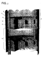
- FIG. 3 schematically shows a three-dimensional image of in FIG. 1 shown in longitudinal section embodiment of a reactor 1 with two superimposed chambers 4, with liquid overflows 6, constructed of three interconnected parts gas distributor 9 with exemplary comb-like outlet openings 11 for the gas in the lower region of the gas distributor 9 and with baffles 12th
- FIG. 4 shows a longitudinal section through a chamber 4 of an embodiment of a reactor according to the invention with a single Gaszutechnischsrohr8 for the supply of a gas stream 3 in a gas distributor 9, which is in the form of a one-piece, closed-top hood 10.
- the insert 15 has drainage pipes 18, which are open at the top and closed at the bottom and, in addition, pipes 19, which are closed at the top and open at the bottom, and which serve to discharge the liquid from the unfavorable spaces 14.
- the cross-sectional representation, in the plane A / A illustrates the circular cross section of the hood 10 and the symmetrical over the cross section of the gas distributor 9 arrangement of the outlet openings 11 for the gas.
- the methyl acetate was removed in the bottom chamber to residual contents of ⁇ 0.1 wt .-% from the reaction solution.
- the liquid height per chamber was 25 cm in each case.
- a gas distributor was arranged, with openings for the gas outlet at a distance of 10 cm below the liquid level. Due to this small hydrostatic pressure difference, only a slight temperature spread, from about 65 to about 68 ° C over the height of the liquid, in the boiling state reaction mixture in each chamber resulted. As a result, no coloring components and thus excellent product quality were obtained.
- the gas distributors were each within a spigot spaced from the liquid surface and from the bottom of the chamber and dividing the chamber into a fumigant and a non-fumigated space having a cross sectional area ratio of 60:40. Due to the good mixing in the chambers, the enrichment of the methyl acetate in the methanol vapor reached about 85 to 95% of the vapor-liquid equilibrium.
- the same transesterification reaction was carried out in a four-stage stirred tank cascade.
- an average residence time of about 8 hours was required compared with the total residence time of 2.5 hours for the process in the reactor according to the invention.
- the coproduct methyl acetate was a methanol vapor amount of 0.8 to 0.9 kg per kg of polytetrahydrofuran used, that is about three times the amount required for the process in the reactor according to the invention methanol vapor amount.
Landscapes
- Chemical & Material Sciences (AREA)
- Chemical Kinetics & Catalysis (AREA)
- Organic Chemistry (AREA)
- Engineering & Computer Science (AREA)
- Combustion & Propulsion (AREA)
- Organic Low-Molecular-Weight Compounds And Preparation Thereof (AREA)
- Devices And Processes Conducted In The Presence Of Fluids And Solid Particles (AREA)
- Physical Or Chemical Processes And Apparatus (AREA)
- Heterocyclic Compounds That Contain Two Or More Ring Oxygen Atoms (AREA)
Applications Claiming Priority (3)
| Application Number | Priority Date | Filing Date | Title |
|---|---|---|---|
| DE10120801A DE10120801A1 (de) | 2001-04-27 | 2001-04-27 | Reaktor für gas/flüssig oder gas/flüssig/fest-Reaktionen |
| DE10120801 | 2001-04-27 | ||
| PCT/EP2002/004653 WO2002087723A1 (de) | 2001-04-27 | 2002-04-26 | Reaktor für gas/flüssig oder gas/flüssig/fest-reaktionen |
Publications (2)
| Publication Number | Publication Date |
|---|---|
| EP1387720A1 EP1387720A1 (de) | 2004-02-11 |
| EP1387720B1 true EP1387720B1 (de) | 2008-02-13 |
Family
ID=7683018
Family Applications (1)
| Application Number | Title | Priority Date | Filing Date |
|---|---|---|---|
| EP02740529A Expired - Lifetime EP1387720B1 (de) | 2001-04-27 | 2002-04-26 | Reaktor für gas/flüssig- oder gas/flüssig/fest-reaktionen |
Country Status (11)
| Country | Link |
|---|---|
| US (1) | US20040151640A1 (enExample) |
| EP (1) | EP1387720B1 (enExample) |
| JP (1) | JP2004533315A (enExample) |
| KR (1) | KR100896369B1 (enExample) |
| CN (1) | CN100402120C (enExample) |
| AT (1) | ATE385845T1 (enExample) |
| DE (2) | DE10120801A1 (enExample) |
| ES (1) | ES2296949T3 (enExample) |
| MY (1) | MY138099A (enExample) |
| TW (1) | TWI239860B (enExample) |
| WO (1) | WO2002087723A1 (enExample) |
Families Citing this family (18)
| Publication number | Priority date | Publication date | Assignee | Title |
|---|---|---|---|---|
| DE10313681A1 (de) * | 2003-03-26 | 2004-10-07 | Basf Ag | Verfahren zur Herstellung von Polyamiden |
| DE10329491A1 (de) | 2003-07-01 | 2005-01-27 | Basf Ag | Reaktor für gas/flüssig oder gas/flüssig/fest Reaktionen |
| DE10330721A1 (de) | 2003-07-08 | 2005-01-27 | Basf Ag | Verfahren zur Gewinnung von Oligomeren des Polytetrahydrofurans oder der Tetrahydrofuran-Copolymere |
| DE102006009150B4 (de) | 2006-02-24 | 2018-07-19 | Basf Se | Verfahren zur Herstellung von Polytetrahydrofuran oder Tetrahydrofuran-Copolymeren |
| DE102006027233A1 (de) | 2006-06-09 | 2007-12-13 | Basf Ag | Verfahren zur Herstellung von Polytetrahydrofuran oder Tetrahydrofuran-Copolymeren |
| DE102006045088A1 (de) * | 2006-09-21 | 2008-03-27 | Basf Ag | Verfahren zum Durchmischen einer in einem im wesentlichen abgeschlossenen Behälter befindlichen Flüssigkeit oder Mischung aus einer Flüssigkeit und einem feinteiligen Feststoff |
| WO2008086919A1 (de) | 2007-01-19 | 2008-07-24 | Basf Se | Verfahren zur änderung des vorgegebenen mittleren molekulargewicht mn bei der kontinuierlichen herstellung von polytetrahydrofuranen oder thf copolymeren |
| KR101554607B1 (ko) | 2008-11-07 | 2015-09-22 | 에스케이케미칼주식회사 | 지방산을 이용한 지방산알킬에스테르의 제조방법 및 장치 |
| KR20110092326A (ko) * | 2008-11-27 | 2011-08-17 | 바스프 에스이 | 증류에 의한 분리 장치 |
| WO2012143309A1 (de) | 2011-04-19 | 2012-10-26 | Basf Se | Verfahren zur herstellung von neopentylglykol |
| CN102319553B (zh) * | 2011-08-30 | 2014-01-29 | 神华集团有限责任公司 | 二甲醚合成反应器 |
| CN109382071A (zh) * | 2018-12-13 | 2019-02-26 | 上海释颉化工技术合伙企业(有限合伙) | 一种用于制备六亚甲基二胺的组合式生成反应器 |
| CN112705124B (zh) * | 2019-10-25 | 2022-07-12 | 中国石油化工股份有限公司 | 用于合成碳酸酯的反应器、系统以及合成碳酸酯的方法 |
| CN112570046A (zh) * | 2020-11-17 | 2021-03-30 | 中国恩菲工程技术有限公司 | 离子交换设备 |
| CN112657433B (zh) * | 2020-12-08 | 2025-04-18 | 上海巽田科技股份有限公司 | 制备金属有机化合物的装置和工艺 |
| RU2752385C1 (ru) * | 2021-01-20 | 2021-07-26 | Общество С Ограниченной Ответственностью "Научно - Исследовательский Институт Технологий Органической, Неорганической Химии И Биотехнологий" | Пленочный тепломассообменный аппарат |
| CN114733451A (zh) * | 2022-04-15 | 2022-07-12 | 青岛科技大学 | 一种停留时间可调的连续化气液反应装置 |
| KR102858818B1 (ko) * | 2022-12-13 | 2025-09-12 | 한국화학연구원 | 마이크로 채널 반응기 |
Family Cites Families (18)
| Publication number | Priority date | Publication date | Assignee | Title |
|---|---|---|---|---|
| DE600442C (de) * | 1930-07-19 | 1934-07-26 | Hermann Frischer | Vorrichtung zur Behandlung von Fluessigkeiten mit Gasen |
| DE859444C (de) * | 1943-05-27 | 1952-12-15 | Basf Ag | Verfahren und Vorrichtung zur kontinuierlichen Druckhydrierung von Kohlen, Teeren und Mineraloelen in fluessiger Phase |
| US2762683A (en) * | 1953-02-27 | 1956-09-11 | Universal Oil Prod Co | Contacting of solid material with liquid phase reactant streams |
| DE1542274A1 (de) * | 1966-07-06 | 1970-03-26 | Koppers Gmbh Heinrich | Verfahren und Vorrichtung zur Durchfuehrung langsam verlaufender chemischer Reaktionen von Gasen mit Fluessigkeiten |
| FR96322E (fr) * | 1968-11-26 | 1972-06-16 | Rhone Poulenc Sa | Nouveau réacteur étagé. |
| DE2847443A1 (de) * | 1978-11-02 | 1980-05-22 | Blenke Heinz | Verfahren und vorrichtung zur durchfuehrung (bio-)chemischer reaktionen und verfahrenstechnischer grundoperationen in fluiden systemen |
| US4526757A (en) * | 1982-11-01 | 1985-07-02 | Exxon Research And Engineering Co. | Pulsed flow vapor-liquid reactor |
| US4483994A (en) * | 1983-02-22 | 1984-11-20 | The Halcon Sd Group, Inc. | Process for the production of alkylene carbonates and oxides |
| US4869851A (en) * | 1987-05-26 | 1989-09-26 | Uni-Frac Inc. | Vapor/liquid contact device and method of mixing a vapor flow and a counter current reflux liquid flow |
| AU637595B2 (en) * | 1989-01-17 | 1993-06-03 | Davy Mckee (London) Limited | Process and apparatus |
| US5130102A (en) * | 1990-06-11 | 1992-07-14 | Chemical Research & Licensing Company | Catalytic distillation reactor |
| US5308592A (en) * | 1990-12-03 | 1994-05-03 | China Petrochemical Corporation (Sinopec) | Equipment for mixed phase reaction distillation |
| FR2684893A1 (fr) * | 1991-12-16 | 1993-06-18 | Inst Francais Du Petrole | Procede de distillation reactive catalytique et appareillage pour sa mise en óoeuvre. |
| US5338517A (en) * | 1992-05-18 | 1994-08-16 | Chemical Research & Licensing Company | Catalytic distillation column reactor and tray |
| DE4237350C2 (de) * | 1992-11-05 | 1996-12-12 | Wildfang Dieter Gmbh | Verfahren zum Stoffübertragen sowie Vorrichtung zur Durchführung des Verfahrens |
| US5799877A (en) * | 1996-01-03 | 1998-09-01 | Exxon Research And Engineering Company | Fluid distribution across a particulate bed |
| US6045762A (en) * | 1997-01-22 | 2000-04-04 | Governors Of The University Of Alberta | Apparatus for catalytic distillation |
| US6103104A (en) * | 1998-05-07 | 2000-08-15 | Exxon Research And Engineering Company | Multi-stage hydroprocessing of middle distillates to avoid color bodies |
-
2001
- 2001-04-27 DE DE10120801A patent/DE10120801A1/de not_active Ceased
-
2002
- 2002-04-26 KR KR1020037013917A patent/KR100896369B1/ko not_active Expired - Fee Related
- 2002-04-26 TW TW091108688A patent/TWI239860B/zh not_active IP Right Cessation
- 2002-04-26 EP EP02740529A patent/EP1387720B1/de not_active Expired - Lifetime
- 2002-04-26 WO PCT/EP2002/004653 patent/WO2002087723A1/de not_active Ceased
- 2002-04-26 MY MYPI20021542A patent/MY138099A/en unknown
- 2002-04-26 ES ES02740529T patent/ES2296949T3/es not_active Expired - Lifetime
- 2002-04-26 CN CNB028089847A patent/CN100402120C/zh not_active Expired - Lifetime
- 2002-04-26 US US10/475,723 patent/US20040151640A1/en not_active Abandoned
- 2002-04-26 JP JP2002585058A patent/JP2004533315A/ja not_active Ceased
- 2002-04-26 AT AT02740529T patent/ATE385845T1/de not_active IP Right Cessation
- 2002-04-26 DE DE50211675T patent/DE50211675D1/de not_active Expired - Lifetime
Also Published As
| Publication number | Publication date |
|---|---|
| WO2002087723A1 (de) | 2002-11-07 |
| DE10120801A1 (de) | 2002-11-07 |
| DE50211675D1 (de) | 2008-03-27 |
| EP1387720A1 (de) | 2004-02-11 |
| KR100896369B1 (ko) | 2009-05-08 |
| MY138099A (en) | 2009-04-30 |
| JP2004533315A (ja) | 2004-11-04 |
| TWI239860B (en) | 2005-09-21 |
| KR20040015133A (ko) | 2004-02-18 |
| CN1505540A (zh) | 2004-06-16 |
| CN100402120C (zh) | 2008-07-16 |
| ES2296949T3 (es) | 2008-05-01 |
| US20040151640A1 (en) | 2004-08-05 |
| ATE385845T1 (de) | 2008-03-15 |
Similar Documents
| Publication | Publication Date | Title |
|---|---|---|
| EP1387720B1 (de) | Reaktor für gas/flüssig- oder gas/flüssig/fest-reaktionen | |
| DE69514357T2 (de) | Zweiphasenverteilungssystem für abwärtsfliessende reaktoren | |
| DE69314881T2 (de) | Katalysatortragender Kolonnenboden mit Ablaufstutzen für chemische Prozesskolonne | |
| DE68902832T2 (de) | Verteilersystem fuer abwaertsfliessende reaktoren. | |
| EP2318129B1 (de) | Parallelisierte strahlschlaufenreaktoren | |
| DE602004001996T2 (de) | Verbesserte Mehrphasenmischvorrichtung mit Einbauten | |
| EP2780093B1 (de) | Boden für eine stoffaustauschkolonne | |
| DE2921428C2 (enExample) | ||
| EP1493475B1 (de) | Reaktor für gas/flüssig oder gas/flüssig/fest Reaktionen | |
| DE60209746T2 (de) | Verfahren zur umsetzung von caprolactam zu nylon 6 | |
| JP2004533315A5 (enExample) | ||
| DE1957458B2 (de) | Vorrichtung zur kontinuierlichen durchfuehrung chemischer umsetzungen in fluessiger phase | |
| EP0106944A2 (de) | Verfahren und Vorrichtung für ein fluidisiertes Feststoffsystem | |
| WO2009056488A1 (de) | Horizontaler reaktor zur umsetzung eines fluiden eduktstromes mit einem fluiden oxidatorstrom in gegenwart eines feststoffkatalysators | |
| DE2157736B2 (de) | Vorrichtung zur kontinuierlichen Kontaktierung von Flüssigkeiten mit Gasen oder von Flüssigkeiten in Gegenwart von Gasen oder von Flüssigkeiten mit Feststoffen in Gegenwart von Gasen oder von Flüssigkeiten mit Gasen und feinverteilten Feststoffen im Gleichstrom | |
| CH618105A5 (enExample) | ||
| DE112006000625T5 (de) | Verfahren zum Betreiben eines Fluidbettreaktors | |
| DE4104333A1 (de) | Verfahren zur mischphasen-reaktionsdestillation | |
| DE69123223T2 (de) | Prozess zur Herstellung von MTBE | |
| DE69012330T2 (de) | Katalysatorstripperanlage und -prozess bei katalytischen krackverfahren. | |
| DE69116286T2 (de) | Katalytisches Verfahren zur Herstellung von Olefinen | |
| CH640423A5 (de) | Stoffaustauschvorrichtung, insbesondere fuer die extraktion. | |
| DE4237350C2 (de) | Verfahren zum Stoffübertragen sowie Vorrichtung zur Durchführung des Verfahrens | |
| DE2634785C2 (de) | Verfahren zum Betrieb von Blasensäulen | |
| EP0207113B1 (de) | Verfahren und vorrichtung zur stoff- und energieübertragung in fluiden stoffsystemen |
Legal Events
| Date | Code | Title | Description |
|---|---|---|---|
| PUAI | Public reference made under article 153(3) epc to a published international application that has entered the european phase |
Free format text: ORIGINAL CODE: 0009012 |
|
| 17P | Request for examination filed |
Effective date: 20031127 |
|
| AK | Designated contracting states |
Kind code of ref document: A1 Designated state(s): AT BE CH CY DE DK ES FI FR GB GR IE IT LI LU MC NL PT SE TR |
|
| AX | Request for extension of the european patent |
Extension state: AL LT LV MK RO SI |
|
| RIN1 | Information on inventor provided before grant (corrected) |
Inventor name: WEINLE, WERNER Inventor name: ZEHNER, PETER Inventor name: BENFER, REGINA Inventor name: NILLES, MICHAEL |
|
| 17Q | First examination report despatched |
Effective date: 20051026 |
|
| GRAP | Despatch of communication of intention to grant a patent |
Free format text: ORIGINAL CODE: EPIDOSNIGR1 |
|
| GRAS | Grant fee paid |
Free format text: ORIGINAL CODE: EPIDOSNIGR3 |
|
| GRAA | (expected) grant |
Free format text: ORIGINAL CODE: 0009210 |
|
| AK | Designated contracting states |
Kind code of ref document: B1 Designated state(s): AT BE CH CY DE DK ES FI FR GB GR IE IT LI LU MC NL PT SE TR |
|
| REG | Reference to a national code |
Ref country code: GB Ref legal event code: FG4D Free format text: NOT ENGLISH |
|
| REG | Reference to a national code |
Ref country code: CH Ref legal event code: EP |
|
| RAP2 | Party data changed (patent owner data changed or rights of a patent transferred) |
Owner name: BASF SE |
|
| REG | Reference to a national code |
Ref country code: IE Ref legal event code: FG4D Free format text: LANGUAGE OF EP DOCUMENT: GERMAN |
|
| REF | Corresponds to: |
Ref document number: 50211675 Country of ref document: DE Date of ref document: 20080327 Kind code of ref document: P |
|
| NLT2 | Nl: modifications (of names), taken from the european patent patent bulletin |
Owner name: BASF SE Effective date: 20080305 |
|
| REG | Reference to a national code |
Ref country code: ES Ref legal event code: FG2A Ref document number: 2296949 Country of ref document: ES Kind code of ref document: T3 |
|
| PG25 | Lapsed in a contracting state [announced via postgrant information from national office to epo] |
Ref country code: FI Free format text: LAPSE BECAUSE OF FAILURE TO SUBMIT A TRANSLATION OF THE DESCRIPTION OR TO PAY THE FEE WITHIN THE PRESCRIBED TIME-LIMIT Effective date: 20080213 |
|
| ET | Fr: translation filed | ||
| REG | Reference to a national code |
Ref country code: IE Ref legal event code: FD4D |
|
| PG25 | Lapsed in a contracting state [announced via postgrant information from national office to epo] |
Ref country code: SE Free format text: LAPSE BECAUSE OF FAILURE TO SUBMIT A TRANSLATION OF THE DESCRIPTION OR TO PAY THE FEE WITHIN THE PRESCRIBED TIME-LIMIT Effective date: 20080513 Ref country code: DK Free format text: LAPSE BECAUSE OF FAILURE TO SUBMIT A TRANSLATION OF THE DESCRIPTION OR TO PAY THE FEE WITHIN THE PRESCRIBED TIME-LIMIT Effective date: 20080213 Ref country code: PT Free format text: LAPSE BECAUSE OF FAILURE TO SUBMIT A TRANSLATION OF THE DESCRIPTION OR TO PAY THE FEE WITHIN THE PRESCRIBED TIME-LIMIT Effective date: 20080714 Ref country code: IE Free format text: LAPSE BECAUSE OF FAILURE TO SUBMIT A TRANSLATION OF THE DESCRIPTION OR TO PAY THE FEE WITHIN THE PRESCRIBED TIME-LIMIT Effective date: 20080213 |
|
| PG25 | Lapsed in a contracting state [announced via postgrant information from national office to epo] |
Ref country code: MC Free format text: LAPSE BECAUSE OF NON-PAYMENT OF DUE FEES Effective date: 20080430 |
|
| REG | Reference to a national code |
Ref country code: CH Ref legal event code: PL |
|
| PLBE | No opposition filed within time limit |
Free format text: ORIGINAL CODE: 0009261 |
|
| STAA | Information on the status of an ep patent application or granted ep patent |
Free format text: STATUS: NO OPPOSITION FILED WITHIN TIME LIMIT |
|
| 26N | No opposition filed |
Effective date: 20081114 |
|
| PG25 | Lapsed in a contracting state [announced via postgrant information from national office to epo] |
Ref country code: LI Free format text: LAPSE BECAUSE OF NON-PAYMENT OF DUE FEES Effective date: 20080430 Ref country code: CH Free format text: LAPSE BECAUSE OF NON-PAYMENT OF DUE FEES Effective date: 20080430 |
|
| PG25 | Lapsed in a contracting state [announced via postgrant information from national office to epo] |
Ref country code: CY Free format text: LAPSE BECAUSE OF FAILURE TO SUBMIT A TRANSLATION OF THE DESCRIPTION OR TO PAY THE FEE WITHIN THE PRESCRIBED TIME-LIMIT Effective date: 20080213 |
|
| PGFP | Annual fee paid to national office [announced via postgrant information from national office to epo] |
Ref country code: ES Payment date: 20090508 Year of fee payment: 8 |
|
| PGFP | Annual fee paid to national office [announced via postgrant information from national office to epo] |
Ref country code: AT Payment date: 20090415 Year of fee payment: 8 Ref country code: FR Payment date: 20090417 Year of fee payment: 8 Ref country code: IT Payment date: 20090423 Year of fee payment: 8 Ref country code: NL Payment date: 20090405 Year of fee payment: 8 |
|
| PGFP | Annual fee paid to national office [announced via postgrant information from national office to epo] |
Ref country code: BE Payment date: 20090428 Year of fee payment: 8 |
|
| PGFP | Annual fee paid to national office [announced via postgrant information from national office to epo] |
Ref country code: GB Payment date: 20090422 Year of fee payment: 8 |
|
| PG25 | Lapsed in a contracting state [announced via postgrant information from national office to epo] |
Ref country code: LU Free format text: LAPSE BECAUSE OF NON-PAYMENT OF DUE FEES Effective date: 20080426 |
|
| PG25 | Lapsed in a contracting state [announced via postgrant information from national office to epo] |
Ref country code: TR Free format text: LAPSE BECAUSE OF FAILURE TO SUBMIT A TRANSLATION OF THE DESCRIPTION OR TO PAY THE FEE WITHIN THE PRESCRIBED TIME-LIMIT Effective date: 20080213 |
|
| PG25 | Lapsed in a contracting state [announced via postgrant information from national office to epo] |
Ref country code: GR Free format text: LAPSE BECAUSE OF FAILURE TO SUBMIT A TRANSLATION OF THE DESCRIPTION OR TO PAY THE FEE WITHIN THE PRESCRIBED TIME-LIMIT Effective date: 20080514 |
|
| BERE | Be: lapsed |
Owner name: BASF A.G. Effective date: 20100430 |
|
| REG | Reference to a national code |
Ref country code: NL Ref legal event code: V1 Effective date: 20101101 |
|
| GBPC | Gb: european patent ceased through non-payment of renewal fee |
Effective date: 20100426 |
|
| REG | Reference to a national code |
Ref country code: FR Ref legal event code: ST Effective date: 20101230 |
|
| PG25 | Lapsed in a contracting state [announced via postgrant information from national office to epo] |
Ref country code: NL Free format text: LAPSE BECAUSE OF NON-PAYMENT OF DUE FEES Effective date: 20101101 Ref country code: AT Free format text: LAPSE BECAUSE OF NON-PAYMENT OF DUE FEES Effective date: 20100426 |
|
| PG25 | Lapsed in a contracting state [announced via postgrant information from national office to epo] |
Ref country code: BE Free format text: LAPSE BECAUSE OF NON-PAYMENT OF DUE FEES Effective date: 20100430 Ref country code: GB Free format text: LAPSE BECAUSE OF NON-PAYMENT OF DUE FEES Effective date: 20100426 Ref country code: IT Free format text: LAPSE BECAUSE OF NON-PAYMENT OF DUE FEES Effective date: 20100426 |
|
| REG | Reference to a national code |
Ref country code: ES Ref legal event code: FD2A Effective date: 20110714 |
|
| PG25 | Lapsed in a contracting state [announced via postgrant information from national office to epo] |
Ref country code: ES Free format text: LAPSE BECAUSE OF NON-PAYMENT OF DUE FEES Effective date: 20110704 |
|
| PG25 | Lapsed in a contracting state [announced via postgrant information from national office to epo] |
Ref country code: ES Free format text: LAPSE BECAUSE OF NON-PAYMENT OF DUE FEES Effective date: 20100427 |
|
| PG25 | Lapsed in a contracting state [announced via postgrant information from national office to epo] |
Ref country code: FR Free format text: LAPSE BECAUSE OF NON-PAYMENT OF DUE FEES Effective date: 20100430 |
|
| PGFP | Annual fee paid to national office [announced via postgrant information from national office to epo] |
Ref country code: DE Payment date: 20190621 Year of fee payment: 18 |
|
| REG | Reference to a national code |
Ref country code: DE Ref legal event code: R119 Ref document number: 50211675 Country of ref document: DE |
|
| PG25 | Lapsed in a contracting state [announced via postgrant information from national office to epo] |
Ref country code: DE Free format text: LAPSE BECAUSE OF NON-PAYMENT OF DUE FEES Effective date: 20201103 |