EP1387001A1 - Verfahren zur Herstellung einer Faserstoffbahn und Doppelsiebformer zur Durchführung des Verfahrens - Google Patents
Verfahren zur Herstellung einer Faserstoffbahn und Doppelsiebformer zur Durchführung des Verfahrens Download PDFInfo
- Publication number
- EP1387001A1 EP1387001A1 EP03102148A EP03102148A EP1387001A1 EP 1387001 A1 EP1387001 A1 EP 1387001A1 EP 03102148 A EP03102148 A EP 03102148A EP 03102148 A EP03102148 A EP 03102148A EP 1387001 A1 EP1387001 A1 EP 1387001A1
- Authority
- EP
- European Patent Office
- Prior art keywords
- wire
- shaking
- roller
- twin
- breast
- Prior art date
- Legal status (The legal status is an assumption and is not a legal conclusion. Google has not performed a legal analysis and makes no representation as to the accuracy of the status listed.)
- Ceased
Links
- 238000004519 manufacturing process Methods 0.000 title claims abstract description 5
- 238000000034 method Methods 0.000 title claims description 11
- 210000000481 breast Anatomy 0.000 claims abstract description 35
- 239000000725 suspension Substances 0.000 claims abstract description 24
- 230000002093 peripheral effect Effects 0.000 claims abstract description 17
- 239000000835 fiber Substances 0.000 claims abstract description 15
- 239000011111 cardboard Substances 0.000 claims abstract description 6
- 239000011087 paperboard Substances 0.000 claims abstract description 6
- 230000015572 biosynthetic process Effects 0.000 claims description 6
- 230000001105 regulatory effect Effects 0.000 claims description 6
- XLYOFNOQVPJJNP-UHFFFAOYSA-N water Substances O XLYOFNOQVPJJNP-UHFFFAOYSA-N 0.000 abstract description 2
- 230000010355 oscillation Effects 0.000 abstract 1
- 230000005087 leaf formation Effects 0.000 description 7
- 230000002996 emotional effect Effects 0.000 description 2
- 230000001133 acceleration Effects 0.000 description 1
- 230000003197 catalytic effect Effects 0.000 description 1
- 230000008878 coupling Effects 0.000 description 1
- 238000010168 coupling process Methods 0.000 description 1
- 238000005859 coupling reaction Methods 0.000 description 1
- 230000001360 synchronised effect Effects 0.000 description 1
Images
Classifications
-
- D—TEXTILES; PAPER
- D21—PAPER-MAKING; PRODUCTION OF CELLULOSE
- D21F—PAPER-MAKING MACHINES; METHODS OF PRODUCING PAPER THEREON
- D21F1/00—Wet end of machines for making continuous webs of paper
- D21F1/18—Shaking apparatus for wire-cloths and associated parts
-
- D—TEXTILES; PAPER
- D21—PAPER-MAKING; PRODUCTION OF CELLULOSE
- D21F—PAPER-MAKING MACHINES; METHODS OF PRODUCING PAPER THEREON
- D21F9/00—Complete machines for making continuous webs of paper
- D21F9/003—Complete machines for making continuous webs of paper of the twin-wire type
Definitions
- the invention relates to a method for producing a fibrous web, in particular a paper or cardboard web, from at least one fiber suspension in a two continuous endless sieves (inner sieve, outer sieve) Twin wire former, the inner wire over a circumferential area Forming roller is guided and the outer wire over a circumferential area Breast roll is guided and then in the area of the forming roll on the inner wire to form a wedge-shaped stock inlet gap, which is directly from a Headbox takes up a fiber suspension, is guided and then a twin-wire section formed by the two screens (inner wire, outer wire) becomes.
- the invention further relates to a twin wire former of a machine for production a fibrous web, in particular a paper or cardboard web, according to the preamble of claim 8.
- twin wire former is from European patent application EP 0 933 473 A2 (PB10656 EP) of the applicant is known.
- the twin wire former shown comprises two revolving endless sieves (inner sieve, outer sieve), from which the inner wire runs over a peripheral region of a forming roller and the outer wire runs over a peripheral area of a breast roll and then in Area of the forming roller on the inner wire to form a wedge-shaped Inlet gap that is a pulp suspension directly from a headbox records, accumulates.
- the two sieves inner sieve, outer sieve
- a twin-wire section in which several drainage elements on both sides are arranged on the lying between the two sieves and Forming fibrous web act.
- the twin wire section they run two screens over a separator, one of the screens of the formed Separates fibrous web and the other sieve.
- This known screen section has the disadvantage that the area of the active Sheet formation begins for the first time in the area of the forming roller. On the quality of the too Forming fibrous web must then after the forming roll with great constructive and technological effort can be positively influenced.
- quality includes all known properties, such as for example, the formation understood.
- a method and a twin wire former improve the type mentioned above so that the area of active leaf formation as soon as possible after the introduction of the fiber suspension between the two sieves begins and then immediately a positive influence on the quality the fibrous web to be formed is possible.
- the fiber suspension is already in the area of the breast roll in the wedge-shaped inlet gap is introduced. This is the maximum free wire draw between the breast roll and the forming roll for active sheet formation used.
- the outer sieve is sufficient if the outer sieve is moved oscillatingly over a shaking distance which is a shaking length of 750 mm, preferably 650 mm, in particular 500 mm.
- the area of active leaf formation becomes noticeable in terms of its efficiency improved, even if that running over the circumferential area of the forming roller Inner wire with at least one acting on the forming roller Shaking device is moved oscillating transversely to the direction of the wire. In order to So both sieves that carry the fibrous web to be formed become oscillating emotional.
- the breast roll and the forming roll are synchronized or asynchronously oscillating moves, the type of movement primarily depends on the configuration the machine and the properties of the fiber suspension used depends.
- the shaker light and easy to use for different applications to be able to adapt with optimal properties it is at least controlled by a control device. It is due to the geometric conditions of the twin wire former, the roller with a small shaking stroke or a high shaking frequency controlled emotional.
- the breast roll is advantageously as a breast forming roll with an open one Surface formed and the fiber suspension already hits already in the area of the breast roller on the outer screen.
- the shaking device a shaking section preferably provided with a fiber suspension acted on, the shaking length of 750 mm, preferably 650 mm, in particular 500 mm.
- the area of active leaf formation becomes noticeable in terms of its efficiency improved if the one encircled by the inner screen over the peripheral region Forming roller with at least one shaker to which it oscillates Movement transverse to the wire running direction is connected.
- the shaker light and easy to use for different applications to be able to adapt with optimal properties it is at least a control device. It is due to the geometric Conditions of the twin wire former at least the shaking stroke or the shaking frequency of the shaking device can be controlled / regulated.
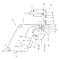
- the single figure shows a schematic side view of an advantageous one Embodiment of the twin wire former according to the invention.
- FIG. 1 shows a schematic side view of a twin wire former 1 a machine for producing a fibrous web 2, in particular a paper or cardboard web, from at least one fiber suspension 3, with two revolving endless sieves (inner sieve 4, outer sieve 5), of which the inner sieve 4 runs over a peripheral region 6 of a forming roller 7 and the outer wire 5 runs over a peripheral region 8 of a breast roller 9 and then in the region the forming roller 7 on the inner wire 4 to form a wedge-shaped Head inlet gap 10, the one of an indicated headbox 11 a Fibrous suspension 3 takes up, runs up at a run-up point A and the two Sieves (inner sieve 4, outer sieve 5) then a twin-wire section 12 form in which, according to the embodiment of FIG.
- the possible design of the twin wire former should not be limited to the embodiment according to FIG. The embodiment according to FIG. 1 is only intended to be exemplary in character Have a large number of possible design variants for the twin-wire former.
- the outer screen 5 extends over the peripheral region 8 rotating breast roller 9 with at least one shaking device 15 to it oscillating movement B (arrow) connected transversely to the running direction S (arrow) is.
- a shaking device 15 is part of the known prior art and is for example from PCT application WO 98/35094 (PB10484 WO) des Applicant or from German patent DE 40 31 974 C2 (PB04723 DE) of the applicant known.
- it comprises a drive unit 16, which preferably by means of a coupling 17 in extension with the axis 18 of the breast roll 9 is connected, the drive unit 16 mostly consisting of a motor 16.1 and an eccentric drive 16.2 connected directly to the clutch 17.
- the drive unit 16 of the shaking device 15 is provided with at least one control device 19 together with preferably an optional acceleration sensor 20 provided so that at least the shaking stroke or the shaking frequency the shaker 15 is controllable.
- An example of such Control / regulating device with regard to detailed structure and functional catalytic converter is in the already mentioned PCT application WO 98/35094 (PB10484 WO) the applicant; the contents of which hereby become the subject of the present description made.
- the breast roller 9 is a breast forming roller 9.1 with an open one Surface 9.2, for example in the form of bores, grooves and the like, educated.
- the fibrous suspension 3 already meets in the area of Breast roll 9 on the outer wire 5. The position and the position of the headbox 11 can be changed.
- the shaking device 15 acts on a shaking section S s , preferably provided with fiber suspension 3, which has a shaking length L s of 750 mm, preferably 650 mm, in particular 500 mm.
- the forming roller 7, which runs from the inner wire 4 over the peripheral area 6, is connected to at least one shaking device 15.1 for its oscillating movement B (arrow) transversely to the wire running direction S (arrow).
- the shaking device 15.1 together with the control / regulating device 19.1 is no longer explicitly shown in FIG. 1, but it has the same or a similar structure as the shaking device 15 of the breast roller 9.
- Their modes of operation are preferably identical. This makes it possible for the breast roller 9 and the forming roller 7 to be moved in an oscillating manner, synchronously or asynchronously.
- the inventive one can also Processes for producing a fibrous web are carried out.
- the invention is a method and a twin wire former of the type mentioned is created, the area active leaf formation as soon as possible after introduction of the fiber suspension begins between the two sieves and then immediately a positive influence on the quality of the fibrous web to be formed is possible.
Landscapes
- Paper (AREA)
Abstract
Description
Dadurch ist es möglich, dass die Brustwalze 9 und die Formierwalze 7 synchron oder asynchron oszillierend bewegt werden.
- 1
- Doppelsiebformer
- 2
- Faserstoffbahn
- 3
- Faserstoffsuspension
- 4
- Innensieb
- 5
- Außensieb
- 6
- Umfangsbereich (Formierwalze)
- 7
- Formierwalze
- 8
- Umfangsbereich (Brustwalze)
- 9
- Brustwalze
- 9.1
- Brustformierwalze
- 9.2
- Offene Oberfläche
- 10
- Stoffeinlaufspalt
- 11
- Stoffauflauf
- 12
- Doppelsiebstrecke
- 13
- Umlenkeinrichtung
- 13.1
- Umlenkwalze
- 14
- Trenneinrichtung
- 15
- Schüttelvorrichtung (Brustwalze)
- 15.1
- Schüttelvorrichtung (Formierwalze)
- 16
- Antriebseinheit
- 16.1
- Motor
- 16.2
- Exzenterantrieb
- 17
- Kupplung
- 18
- Achse
- 19
- Steuer-/Regeleinrichtung (Brustwalze)
- 19.1
- Steuer-/Regeleinrichtung (Formierwalze)
- 20
- Beschleunigungssensor
- A
- Auflaufpunkt (Außensieb)
- B
- Oszillierende Bewegung (Pfeil)
- Ls
- Schüttellänge
- S
- Sieblaufrichtung (Pfeil)
- Ss
- Schüttelstrecke
Claims (13)
- Verfahren zur Herstellung einer Faserstoffbahn (2), insbesondere einer Papier- oder Kartonbahn, aus mindestens einer Faserstoffsuspension (3) in einem zwei umlaufende endlose Siebe (Innensieb (4), Außensieb (5)) aufweisenden Doppelsiebformer (1), wobei das Innensieb (4) über einen Umfangsbereich (6) einer Formierwalze (7) geführt wird und das Außensieb (5) über einen Umfangsbereich (8) einer Brustwalze (9) geführt wird und danach im Bereich der Formierwalze (7) auf das Innensieb (4) unter Bildung eines keilförmigen Stoffeinlaufspalts (10), der unmittelbar von einem Stoffauflauf (11) eine Faserstoffsuspension (3) aufnimmt, geführt wird und anschließend eine Doppelsiebstrecke (12) durch die beiden Siebe (Innensieb (4), Außensieb (5)) gebildet wird,
dadurch gekennzeichnet, dass das Außensieb (5) zwischen der Brustwalze (9) und dem Auflaufpunkt (A) auf die Formierwalze (7) mittels mindestens einer an der Brustwalze (9) wirkenden Schüttelvorrichtung (15) quer zur Sieblaufrichtung (S) (Pfeil) oszillierend bewegt wird. - Verfahren nach Anspruch 1,
dadurch gekennzeichnet, dass die Faserstoffsuspension (3) bereits im Bereich der Brustwalze (9) in den keilförmigen Einlaufspalt (10) eingebracht wird. - Verfahren nach Anspruch 1 oder 2,
dadurch gekennzeichnet, dass das Außensieb (5) über eine Schüttelstrecke (Ss) oszillierend bewegt wird, die eine Schüttellänge (Ls) von 750 mm, vorzugsweise 650 mm, insbesondere 500 mm, aufweist. - Verfahren nach einem der vorhergehenden Ansprüche,
dadurch gekennzeichnet, dass das über den Umfangsbereich (6) der Formierwalze (7) laufende Innensieb (4) mit mindestens einer an der Formierwalze (7) wirkenden Schüttelvorrichtung (15.1) quer zur Sieblaufrichtung (S) (Pfeil) oszillierend bewegt wird. - Verfahren nach Anspruch 4,
dadurch gekennzeichnet, dass die Brustwalze (9) und die Formierwalze (7) synchron oder asynchron oszillierend bewegt werden. - Verfahren nach einem der vorhergehenden Ansprüche,
dadurch gekennzeichnet, dass die Schüttelvorrichtung (15, 15.1) mit mindestens einer Steuer-/Regeleinrichtung (19) gesteuert/geregelt wird. - Verfahren nach Anspruch 6,
dadurch gekennzeichnet, dass die Walze (7, 9) mit einem kleinen Schüttelhub beziehungsweise einer hohen Schüttelfrequenz gesteuert/geregelt bewegt wird. - Doppelsiebformer (1) einer Maschine zur Herstellung einer Faserstoffbahn (2), insbesondere einer Papier- oder Kartonbahn, aus mindestens einer Faserstoffsuspension (3), mit zwei umlaufenden endlosen Sieben (Innensieb (4), Außensieb (5)), von denen das Innensieb (4) über einen Umfangsbereich (6) einer Formierwalze (7) läuft und das Außensieb (5) über einen Umfangsbereich (8) einer Brustwalze (9) läuft und danach im Bereich der Formierwalze (7) auf das Innensieb (4) unter Bildung eines keilförmigen Stoffeinlaufspalts (10), der unmittelbar von einem Stoffauflauf (11) eine Faserstoffsuspension (3) aufnimmt, aufläuft und die beiden Siebe (Innensieb (4), Außensieb (5)) anschließend eine Doppelsiebstrecke (12) bilden,
dadurch gekennzeichnet, dass die von dem Außensieb (5) über dem Umfangsbereich (8) umlaufene Brustwalze (9) mit mindestens einer Schüttelvorrichtung (15) zu derer oszillierender Bewegung (B) (Pfeil) quer zur Sieblaufrichtung (S) (Pfeil) verbunden ist. - Doppelsiebformer (1) nach Anspruch 8,
dadurch gekennzeichnet, dass die Brustwalze (9) als eine Brustformierwalze (9.1) mit einer offenen Oberfläche (9.2) ausgebildet ist und die Faserstoffsuspension (3) bereits schon im Bereich der Brustwalze (9) auf das Außensieb (5) auftrifft. - Doppelsiebformer (1) nach Anspruch 8 oder 9,
dadurch gekennzeichnet, dass die Schüttelvorrichtung (15) eine vorzugsweise mit Faserstoffsuspension (3) versehene Schüttelstrecke (Ss) beaufschlagt, die eine Schüttellänge (Ls) von 750 mm, vorzugsweise 650 mm, insbesondere 500 mm, aufweist. - Doppelsiebformer (1) nach einem der Ansprüche 8 bis 10,
dadurch gekennzeichnet, dass die von dem Innensieb (4) über dem Umfangsbereich (6) umlaufene Formierwalze (7) mit mindestens einer Schüttelvorrichtung (15.1) zu derer oszillierender Bewegung (B) (Pfeil) quer zur Sieblaufrichtung (S) (Pfeil) verbunden ist. - Doppelsiebformer (1) nach einem der Ansprüche 8 bis 11,
dadurch gekennzeichnet, dass die Schüttelvorrichtung (15, 15.1) mit mindestens einer Steuer-/Regeleinrichtung (19, 19.1) versehen ist. - Doppelsiebformer (1) nach Anspruch 12,
dadurch gekennzeichnet, dass mindestens der Schüttelhub beziehungsweise die Schüttelfrequenz der Schüttelvorrichtung (15, 15.1) steuer-/regelbar ist.
Applications Claiming Priority (2)
| Application Number | Priority Date | Filing Date | Title |
|---|---|---|---|
| DE2002135588 DE10235588A1 (de) | 2002-08-03 | 2002-08-03 | Verfahren und Doppelsiebformer einer Maschine zur Herstellung einer Faserstoffbahn |
| DE10235588 | 2002-08-03 |
Publications (1)
| Publication Number | Publication Date |
|---|---|
| EP1387001A1 true EP1387001A1 (de) | 2004-02-04 |
Family
ID=30010585
Family Applications (1)
| Application Number | Title | Priority Date | Filing Date |
|---|---|---|---|
| EP03102148A Ceased EP1387001A1 (de) | 2002-08-03 | 2003-07-15 | Verfahren zur Herstellung einer Faserstoffbahn und Doppelsiebformer zur Durchführung des Verfahrens |
Country Status (2)
| Country | Link |
|---|---|
| EP (1) | EP1387001A1 (de) |
| DE (1) | DE10235588A1 (de) |
Citations (3)
| Publication number | Priority date | Publication date | Assignee | Title |
|---|---|---|---|---|
| US5560808A (en) * | 1995-02-21 | 1996-10-01 | Voith Sulzer Papiermaschinen Gmbh | Hydraulically actuated breast roll shake |
| DE19709294A1 (de) * | 1997-03-07 | 1998-09-10 | Voith Sulzer Papiermasch Gmbh | Siebpartie und Verfahren zur Blattbildung in einer Siebpartie |
| EP1081279A2 (de) * | 1999-09-01 | 2001-03-07 | Voith Paper Patent GmbH | Vorrichtung zur Entwässerung eines Stoff-Wasser-Gemisches |
-
2002
- 2002-08-03 DE DE2002135588 patent/DE10235588A1/de not_active Withdrawn
-
2003
- 2003-07-15 EP EP03102148A patent/EP1387001A1/de not_active Ceased
Patent Citations (3)
| Publication number | Priority date | Publication date | Assignee | Title |
|---|---|---|---|---|
| US5560808A (en) * | 1995-02-21 | 1996-10-01 | Voith Sulzer Papiermaschinen Gmbh | Hydraulically actuated breast roll shake |
| DE19709294A1 (de) * | 1997-03-07 | 1998-09-10 | Voith Sulzer Papiermasch Gmbh | Siebpartie und Verfahren zur Blattbildung in einer Siebpartie |
| EP1081279A2 (de) * | 1999-09-01 | 2001-03-07 | Voith Paper Patent GmbH | Vorrichtung zur Entwässerung eines Stoff-Wasser-Gemisches |
Also Published As
| Publication number | Publication date |
|---|---|
| DE10235588A1 (de) | 2004-04-01 |
Similar Documents
| Publication | Publication Date | Title |
|---|---|---|
| DE69010976T2 (de) | Papierbahn formendes Verfahren und Vorrichtung. | |
| DE69308904T2 (de) | Blattbildungspartie für eine Papiermaschine | |
| EP0656967B1 (de) | Formiersieb | |
| EP0486814B1 (de) | Nassteil einer Doppelsieb-Papiermaschine | |
| EP2739780A1 (de) | Blattbildungssystem für eine maschine zur herstellung einer zwei- oder mehrschichtigen faserstoffbahn | |
| DE2547730A1 (de) | Bahnformungsteil in einer gewebepapiermaschine | |
| DE3131957A1 (de) | Entwaesserungseinheit fuer langsieb-papiermaschinen | |
| EP2126202B1 (de) | Verfahren zum entwässern von zellstoff und entwässerungsmaschine zur durchführung des verfahrens | |
| EP1280959B1 (de) | Doppelsiebformer | |
| DE102004047518A1 (de) | Verfahren und Schrägsiebformer einer Maschine zur Herstellung einer Faserstoffbahn aus mindestens einer Faserstoffsuspension | |
| DE10235588A1 (de) | Verfahren und Doppelsiebformer einer Maschine zur Herstellung einer Faserstoffbahn | |
| DE20104380U1 (de) | Doppelsiebformer | |
| EP2096207A1 (de) | Schrägsiebformer einer Maschine zur Herstellung einer Faserstoffbahn aus mindestens einer Faserstoffsuspension | |
| DE102021107854A1 (de) | Mehrlagenformer | |
| EP4328376B1 (de) | Schrägsiebformer | |
| AT504007B1 (de) | Former einer papier- oder kartonmaschine | |
| DE10350758A1 (de) | Verfahren und Doppelsiebformer einer Maschine zur Herstellung einer Faserstoffbahn | |
| DE102010041730A1 (de) | Maschine für die Entwässerung von Zellstoff | |
| EP1803848A1 (de) | Blattbildungsvorrichtung zum Bilden einer Faserstoffbahn | |
| DE202004002985U1 (de) | Doppelsiebformer einer Maschine zur Herstellung einer Faserstoffbahn | |
| DE102011081312A1 (de) | Doppelsiebformer für eine Maschine zur Herstellung einer Faserstoffbahn aus wenigstens einer Faserstoffsuspension | |
| WO2010012676A2 (de) | Doppelsiebformer für eine maschine zur herstellung einer faserstoffbahn | |
| EP1489225A2 (de) | Vorrichtung zur Verbesserung der Eigenschaften einer in einer Blattbildungseinrichtung hergestellten Faserstoffbahn | |
| DE102004000061A1 (de) | Doppelsiebformer einer Maschine zur Herstellung einer Faserstoffbahn und Verfahren zum Umbau eines Doppelsiebformers einer Maschine zur Herstellung einer Faserstoffbahn | |
| DE69220160T2 (de) | Verfahren und vorrichtung zur verbesserten doppelsiebformation |
Legal Events
| Date | Code | Title | Description |
|---|---|---|---|
| PUAI | Public reference made under article 153(3) epc to a published international application that has entered the european phase |
Free format text: ORIGINAL CODE: 0009012 |
|
| AK | Designated contracting states |
Kind code of ref document: A1 Designated state(s): AT BE BG CH CY CZ DE DK EE ES FI FR GB GR HU IE IT LI LU MC NL PT RO SE SI SK TR |
|
| AX | Request for extension of the european patent |
Extension state: AL LT LV MK |
|
| 17P | Request for examination filed |
Effective date: 20040804 |
|
| AKX | Designation fees paid |
Designated state(s): AT BE BG CH CY CZ DE DK EE ES FI FR GB GR HU IE IT LI LU MC NL PT RO SE SI SK TR |
|
| RAP1 | Party data changed (applicant data changed or rights of an application transferred) |
Owner name: VOITH PATENT GMBH |
|
| 17Q | First examination report despatched |
Effective date: 20060113 |
|
| STAA | Information on the status of an ep patent application or granted ep patent |
Free format text: STATUS: THE APPLICATION HAS BEEN REFUSED |
|
| 18R | Application refused |
Effective date: 20070728 |