EP1384804A1 - Procédé pour limiter l'encrassement d'une aiguilleteuse par des fibres volantes et une aiguilleteuse mettant en oeuvre ledit procédé - Google Patents
Procédé pour limiter l'encrassement d'une aiguilleteuse par des fibres volantes et une aiguilleteuse mettant en oeuvre ledit procédé Download PDFInfo
- Publication number
- EP1384804A1 EP1384804A1 EP03291659A EP03291659A EP1384804A1 EP 1384804 A1 EP1384804 A1 EP 1384804A1 EP 03291659 A EP03291659 A EP 03291659A EP 03291659 A EP03291659 A EP 03291659A EP 1384804 A1 EP1384804 A1 EP 1384804A1
- Authority
- EP
- European Patent Office
- Prior art keywords
- plate
- needles
- blowing
- air
- needling
- Prior art date
- Legal status (The legal status is an assumption and is not a legal conclusion. Google has not performed a legal analysis and makes no representation as to the accuracy of the status listed.)
- Granted
Links
- 239000000835 fiber Substances 0.000 title claims abstract description 31
- 238000000034 method Methods 0.000 title claims description 15
- 238000007664 blowing Methods 0.000 claims description 37
- 230000035515 penetration Effects 0.000 claims description 3
- 239000002657 fibrous material Substances 0.000 abstract 1
- 238000004140 cleaning Methods 0.000 description 9
- 235000020303 café frappé Nutrition 0.000 description 5
- 230000005484 gravity Effects 0.000 description 2
- 239000000470 constituent Substances 0.000 description 1
- 230000036461 convulsion Effects 0.000 description 1
- 230000004907 flux Effects 0.000 description 1
Images
Classifications
-
- D—TEXTILES; PAPER
- D04—BRAIDING; LACE-MAKING; KNITTING; TRIMMINGS; NON-WOVEN FABRICS
- D04H—MAKING TEXTILE FABRICS, e.g. FROM FIBRES OR FILAMENTARY MATERIAL; FABRICS MADE BY SUCH PROCESSES OR APPARATUS, e.g. FELTS, NON-WOVEN FABRICS; COTTON-WOOL; WADDING ; NON-WOVEN FABRICS FROM STAPLE FIBRES, FILAMENTS OR YARNS, BONDED WITH AT LEAST ONE WEB-LIKE MATERIAL DURING THEIR CONSOLIDATION
- D04H18/00—Needling machines
- D04H18/02—Needling machines with needles
Definitions
- the present invention relates to a method for limiting the fouling of a needling machine by the flying fibers composing the needling sheet, more particularly to limit the fouling of needling and needling plates, and by extension boards for needles.
- the present invention also proposes a needling device this process.
- a needling machine conventionally comprises at least one board, equipped with a set of parallel needles, actuated back and forth following the longitudinal direction of the needles to repeatedly penetrate through a layer of fibers so as to consolidate the sheet by intertwining the fibers that compose it.
- the fiber path in the work area of the needles is conventionally defined between two plates provided with perforations for the passage of needles.
- the plate on the side where find the needles when in the retracted position is called “cleaning plate”. It serves to prevent the web of fibers from being driven by the needles in their movement back to the position withdrawal.
- the other plate used to prevent the sheet of fibers from being pushed by the tips of the needles, is called “needling plate”.
- fibers may be more or less driven by the needles outside the two plates. These fibers tend to clog the needle holes in the plates and also to accumulate with time at the base of the needles forming a very hard mattress capable of deforming the pad at the moment the striking of needles. Both plates, de-stuffing and needling, as well as the needle board or needles therefore require to be periodically disassembled for cleaning. These operations Disassembly and reassembly require stopping the machine and have a significant cost of labor. It is therefore important especially to reduce the frequency.
- the present invention proposes a solution for achieving this goal.
- Air under pressure is thus projected above and / or below plates, and between the needles as they pass.
- the fibers of the sheet may be driven or pushed by the needles outside the plates are driven laterally before that they do not accumulate and form a mattress near the board at the base of the needles.
- the fibers driven by the lateral blowing fall then by gravity next to the plates and out of the machine by the openings conventionally present in this type of machine. Fibers hunted can also be sucked by the means of aspiration also classically present in this type of machine in particular under the needling plate. Thanks to the invention, the frequency of cleaning is greatly reduced or even eliminated.
- High velocity air jets can be typically obtained guiding air under pressure through small orifices dimensions, practiced for example in a blowing ramp powered by a source of pressurized air.
- the blowing can be achieved in different ways depending the plate concerned and also depending on the type of machine (single or double strike and double needling vis-à-vis).
- the blowing can be carried out discontinuously for alternating periods of blowing with periods of stopping. This may allow to run in jerks to pick up fibers or else to reconstitute with the aid of a booster, during periods of arrest, high pressure air supply from an existing air network compressed.
- Means for managing the characteristics of the air flows at produce and if necessary blowing periods can be provided.
- the blowing is carried out preferably closer to the flush with the plates and horizontally.
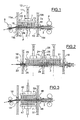
- the needling machine shown in Figure 1 comprises a plate perforated needling needle 1 generally horizontal and a plate of retaining 2, also called “unclogging plate”, placed approximately parallel to a certain distance above the plate 1.
- the plate 2 and the needling plate 1 define between them a path in a substantially horizontal plane for a fiber web 3.
- the stripping plate 2 comprises perforations aligned with those of plate 1.
- introducers 4 schematically in the form of a pair of rollers motors between which passes the web 3.
- the sheet 3 consolidated and compacted by needling is driven by means extractors 6 also schematized by two drive rollers between which passes the sheet 3.
- the stripping plate 2 is placed between the path of the sheet 3 and a needle board 7.
- the board 7 bears on the side of the plate of débourrage 2 a large number of needles 8 oriented perpendicularly in the plane of the path of the ply 3, with their point directed towards the ply 3.
- Each needle is positioned in front of a perforation of the plate of clearing 2 and a corresponding perforation of the plate 1.
- the needle board 7 is fixed to a support beam 9 itself attached to the end of at least a rod 11 slidably mounted along an axis 12, parallel to the needles 8 and perpendicular to the plane of the path of the web 3.
- the crew mobile device consisting of one or more sliding rods 11, of the support beam 9 and board 7 is animated in service of an alternating motion of back and forth in direction 12 between a position 7a in which the end of the needles, designated in this case by 8a, passes through the plate 2, the sheet 3 and the plate 1, and a position of clearance shown in solid lines, in which the needles 8 are completely cleared at least of the plate 1 and the sheet 3, and preferentially the cleaning plate 2.
- the mechanism operating back and forth is not described in more detail here.
- the cleaning plate 2 is fixed on two lateral uprights upper 15a and 15b of the needling frame while the plate needling 1 is attached to two lower side uprights 15c and 15d. Means (not visible in Figure 1) are provided to allow the disassembly and easy reassembly of these plates 1 and 2.
- a blowing ramp 16 is arranged above the cleaning plate 2 so as to chase laterally the fibers which in operation are driven upwards outside the cleaning plate by the movement back and forth needles.
- a second blowing ramp 17 is provided below the needling plate 1 to move laterally the fibers which are driven by the needles under the needling plate 1.
- Ramps 16 and 17 each consist of a hollow tube fixed here respectively on the lateral amount of the upper frame 15a and lower 15c of the frame of the needling machine, and so as to extend longitudinally facing the edge of needles 10 of the board 7 at the passage thereof, perpendicular to the direction of transport of the web 3.
- the ramps 16 and 17 are arranged on the same side 15a of the machine corresponding to the exit of the tablecloth 3.
- the tubes are equipped of small diameter blow holes, arranged in line with the edge of needles 10, and so that the jets of air thrown by these orifices are substantially horizontal, perpendicular to the edge of needles 10 (schematized by arrows F) and as close as possible to flush faces of the plates 1 and 2.
- Conventional and known means per se are used to fix the blowing ramps 16 and 17.
- the interior of each ramp is placed in communication, preferably by both end of the ramp, with a source of air under pressure, for example thanks to a system of pipes fixed to the frame of the needling machine and connected to an air cylinder under pressure.
- the pressure of the bottle is preferably selected high, typically 9 bar, allowing to obtain, given the different pressure losses, air jets able to effectively chase the fibers out of the plates.
- of the control valves possibly automated, are also provided between the cylinder and the ramps to adjust the characteristics of the jets air expelled through the blowing outlets of the ramps. Means are also intended to then automatically control the closure and opening the valves to create blowing periods and stopping periods during operation of the needling machine.
- openings 18 are formed in the side mount amount 15b located opposite the machine. The openings 18 are formed at the base of the lateral upright next to the blow direction. They are spread over the length of the machine, at least along the length opposite the blowing ramp on the opposite side mount jamb.
- blowing ramps can be arranged parallel to the direction of movement of the sheet, on the front or the back of the machine.
- the needling machine shown in FIG. 2 is a single needling machine typing conventionally comprising two needle boards 20 and 21 disposed side by side on the path of the sheet 3 to needling and allowing to practice therefore a double needling of the tablecloth 3. It comprises conventionally for the two boards only one pad 22 and a single needling plate 23. These different constituent parts have the same characteristics as in the needling machine of Figure 1 and the boards 20 and 21 are of similar way operated back and forth.
- blowing on the outside of the machine plate 22 is preferably made, as seen on FIG. 2, using two blow ramps 24, 25, similar to FIG. those of Figure 1, but installed on the central upright 26 of the frame of the machine and in such a way as to advantageously direct each the flow of air towards the outside of the machine in opposite directions (F1, F2) one to the other.
- openings 18 are formed in the outer lateral uprights of frame suitable for evacuation outside the fiber machine blown by the ramps 24 and 25.
- FIG. 2 also illustrates the fact that, according to the invention, use under the needling plate 23 two screw blowing ramps to screws, such as 28, 29 on the side of the board 20, replacing a single ramp 17 as in Figure 1.
- This allows you to use less pressure by aiming to reach only half the distance between two ramps.
- we will advantageously alternate blowing by one and the other of the ramps 27, 28 so as not to upset flows.
- one can also in the case of a simple two-ply machine, prefer that the whole of the blowing is performed from the central frame uprights.
- FIG. 4 illustrates another type of needling machine, called double strikes, to which the invention can be applied.
- the needling machine distinguished by two needle boards moved back and forth symmetrically: a board 45 located above a plate of 46, as in the machines of Figures 1 and 3, and a board 47 located symmetrically below the second plate 48, constituting in this case also a cleaning plate.
- the sheet 3 is thus needled on both sides (with an alternating movement of the boards).
- it is preferably provided a single blowing ramp 50 on the face outer surface of the cleaning plate 46.
- it is preferably provided a single ramp 51 to blow on the outer face of the unclogging plate 48 of course that the fibers do not fall back onto the needle board 47.
- Openings 18 in the side frame uprights allow here too to evacuate from the machine the air laden with blown fibers by the ramps 50 and 51.
- ramps 50 and 51 on the side of the entrance of the web 3 in the needling machine. This may be advantageous for some types of volatile fibers.
Landscapes
- Engineering & Computer Science (AREA)
- Textile Engineering (AREA)
- Nonwoven Fabrics (AREA)
- Preliminary Treatment Of Fibers (AREA)
- Laminated Bodies (AREA)
Abstract
Description
- d'une manière générale, pour une plaque située au dessus de la nappe, le soufflage est de préférence réalisé latéralement selon une seule direction et de manière à chasser les fibres latéralement à l'extérieur de la plaque ; s'il s'agit d'une aiguilleteuse à double frappe, dans laquelle deux planches à aiguilles sont placées côte à côte selon le trajet de la nappe, le soufflage est de préférence réalisé depuis une partie centrale de bâti entre les deux planches à aiguilles et selon deux sens opposés vers les montants latéraux extérieurs de bâti.
- pour une plaque située en dessous de la nappe, le soufflage peut être réalisé indifféremment selon un seul sens ou deux sens opposés, les fibres tombant par gravité automatiquement en dessous des plaques ou étant aspirées ; la puissance de soufflage est par ailleurs adaptée pour que les jets d'air atteignent le milieu de la section de passage des aiguilles et le soufflage est réalisé de préférence alternativement d'un côté puis de l'autre pour éviter que les flux d'air se contrarient ; s'il s'agit d'une aiguilleteuse à double frappe, c'est-à-dire comportant deux planches à aiguilles en vis à vis, une planche en dessus et une planche en dessous de la nappe, le soufflage en dessous de la nappe est de préférence réalisé latéralement selon un seul sens et de manière à chasser les fibres vers l'extérieur de la plaque et éviter qu'elles ne retombent sur la planche à aiguilles du dessous.
- la figure 1 est une vue schématique en élévation en coupe partielle d'une aiguilleteuse selon l'invention à simple frappe avec une planche;
- la figure 2 est une vue similaire à la figure 1 montrant une aiguilleteuse selon l'invention à simple frappe avec deux planches ; et
- la figure 3 est une vue similaire aux figures 1 et 2 montrant une aiguilleteuse à double frappe selon l'invention.
Claims (20)
- Procédé pour limiter l'encrassement d'une aiguilleteuse par les fibres volantes composant une nappe (3) à aiguilleter, l'aiguilleteuse comportant au moins une planche (7, 20, 21, 45, 47) supportant un jeu d'aiguilles (8) parallèles, ladite planche étant actionnée en va et vient entre une position de retrait des aiguilles et une position de pénétration maximale des aiguilles à travers une première plaque (2, 22, 46, 48), la nappe à aiguilleter (3) et une seconde plaque (1, 23, 46, 48), caractérisé en ce qu'il consiste à projeter de l'air sous pression latéralement sur la face extérieure, qui n'est pas en contact avec la nappe, d'au moins l'une desdites plaques (1, 2, 22, 23, 46, 48) pendant au moins une partie du temps de fonctionnement de l'aiguilleteuse.
- Procédé selon la revendication 1, caractérisé en ce que l'air est projeté sous forme de jets (F) formés par de l'air sous pression projeté à travers des orifices de petits dimensions.
- Procédé selon la revendication 1 ou 2, caractérisé en ce que l'air est projeté par intermittence.
- Procédé selon l'une des revendications 1 à 3, caractérisé en ce que l'air est projeté latéralement selon un sens et de manière à chasser latéralement les fibres hors de la machine.
- Procédé selon l'une des revendications 1 à 3, caractérisé en ce que l'air est projeté latéralement alternativement selon deux sens opposés et de manière à couvrir au moins la moitié de la section de passage desdites aiguilles.
- Procédé selon l'une des revendications précédentes, caractérisé en ce que la direction de soufflage est horizontale.
- Procédé selon l'une des revendications précédentes, caractérisé en ce que le soufflage est réalisé au ras de la plaque (1, 2, 22, 23, 46, 48).
- Procédé selon l'une des revendications précédentes, caractérisé en ce que le soufflage est réalisé sur la face extérieure de la plaque (2, 22, 46, 48) située du côté de la position de retrait des aiguilles et selon un seul sens latéral de soufflage.
- Procédé selon la revendication 9, caractérisé en ce que le soufflage est réalisé en outre sur la face extérieure de la plaque (1, 23) située du côté de la position de pénétration des aiguilles et selon deux sens latéraux opposés de soufflage.
- Procédé selon l'une des revendications précédentes, caractérisé en ce que lorsque l'air est projeté dans un seul sens, il est projeté depuis l'entrée de la nappe à aiguilleter, dans le sens d'avancée de ladite nappe.
- Aiguilleteuse pour la mise en oeuvre du procédé selon l'une quelconque des revendications précédentes, comprenant :caractérisée par des moyens de soufflage (16, 17; 24, 25, 28, 29, 50, 51) adaptés à projeter de l'air sous pression latéralement sur la face extérieure, qui n'est pas en contact avec la nappe, d'au moins l'une desdites plaques (1, 2, 22, 23, 46, 48).un bâti (15a, 15b ; 26) ;la première plaque (2, 22, 46, 48) ;la seconde plaque (1, 23, 46, 48) ; etau moins une planche (7 ; 20, 21, 45, 47) sur laquelle font saillie les aiguilles (8), reliée à un mécanisme d'actionnement pour réaliser le déplacement en va et vient ;
- Aiguilleteuse selon la revendication 11, caractérisée en ce que lesdits moyens de soufflage comprennent :au moins une rampe latérale de soufflage (16, 17; 24, 25, 28, 29, 50, 51) montée sur ledit bâti (15a, 15b, 15c, 15d, 26) et comportant des orifices de soufflage adaptés à projeter des jets d'air sur ladite face extérieure de plaque ; etdes moyens de production d'air sous pression destinés à être mis en communication avec l'intérieur de ladite rampe.
- Aiguilleteuse selon la revendication 12, caractérisée par une rampe (16, 24, 25, 50, 51) située sur ledit bâti de manière à projeter des jets d'air sur la face extérieure de plaque située en regard des aiguilles en position de retrait au moins sur la section de passage des aiguilles.
- Aiguilleteuse selon la revendication 12 ou 13, caractérisée par une seconde rampe latérale de soufflage (17, 28, 29) située sur ledit bâti de manière à projeter des jets d'air sur la face extérieure de la seconde plaque (1, 23, 48) au moins sur la section de passage des aiguilles.
- Aiguilleteuse selon la revendication 12 ou 13, caractérisée par deux rampes latérales de soufflage (28, 29) situées sur le bâti de manière à projeter des jets d'air sur la face extérieure de la seconde plaque (23) selon deux sens opposés au moins sur la moitié de la section de passage des aiguilles.
- Aiguilleteuse selon l'une des revendications 11 à 15, cararactérisée en ce que chaque rampe (16, 24, 25, 50, 51) est située au plus près au ras de la plaque correspondante et de manière à projeter des jets d'air selon une direction horizontale.
- Aiguilleteuse selon l'une des revendications 11 à 16, caractérisée en ce que le bâti comporte des ouvertures (18) dans ses montants latéraux extérieurs permettant à l'air chargé des fibres soufflées d'être chassés hors de l'aiguilleteuse.
- Aiguilleteuse selon l'une des revendications 11 à 17, caractérisée en ce que la ou les rampes de soufflage sont prévues sur le bâti de l'aiguilleteuse du côté de l'entrée de la nappe, adaptées à souffler dans le sens d'avancée de la nappe.
- Aiguilleteuse selon l'une des revendications 11 à 18, caractérisée en ce qu'elle est double frappe, comportant deux planches d'aiguilles (45,47) disposées en vis à vis au dessus et en dessous de la nappe à aiguilleter.
- Aiguilleteuse selon l'une des revendications 11 à 19, caractérisée en ce qu'elle est simple frappe, comportant deux planches d'aiguilles (20,21) disposées côte à côte selon le trajet de la nappe (3) à aiguilleter et une partie centrale de bâti (26) entre les deux planches (20, 21), les moyens de soufflage (24, 25) sont adaptés à projeter l'air sous pression latéralement selon deux sens opposés depuis la partie centrale de bâti (26) et de manière de chaque côté à chasser les fibres hors de ladite plaque.
Applications Claiming Priority (2)
| Application Number | Priority Date | Filing Date | Title |
|---|---|---|---|
| FR0209578A FR2842835B1 (fr) | 2002-07-26 | 2002-07-26 | Procede pour limiter l'encrassement d'une aiguilleteuse par des fibres volantes et une aiguilleteuse mettant en oeuvre ledit procede |
| FR0209578 | 2002-07-26 |
Publications (2)
| Publication Number | Publication Date |
|---|---|
| EP1384804A1 true EP1384804A1 (fr) | 2004-01-28 |
| EP1384804B1 EP1384804B1 (fr) | 2007-10-24 |
Family
ID=29797686
Family Applications (1)
| Application Number | Title | Priority Date | Filing Date |
|---|---|---|---|
| EP03291659A Expired - Lifetime EP1384804B1 (fr) | 2002-07-26 | 2003-07-04 | Procédé pour limiter l'encrassement d'une aiguilleteuse par des fibres volantes et une aiguilleteuse mettant en oeuvre ledit procédé |
Country Status (4)
| Country | Link |
|---|---|
| EP (1) | EP1384804B1 (fr) |
| AT (1) | ATE376599T1 (fr) |
| DE (1) | DE60317016T2 (fr) |
| FR (1) | FR2842835B1 (fr) |
Cited By (6)
| Publication number | Priority date | Publication date | Assignee | Title |
|---|---|---|---|---|
| FR2880635A1 (fr) * | 2004-11-24 | 2006-07-14 | Asselin Soc Par Actions Simpli | Aiguilleteuse a hauteur de tete reglable |
| US20240141572A1 (en) * | 2022-10-31 | 2024-05-02 | Rohr, Inc. | Systems and methods for spray cleaning needles for through thickness reinforcement of resin-infused fabrics |
| CN118207687A (zh) * | 2024-05-20 | 2024-06-18 | 海阳市清鸿制衣有限公司 | 一种服装生产用滚压装置 |
| US12297572B2 (en) | 2022-10-31 | 2025-05-13 | Rohr, Inc. | Systems and methods for self-cleaning needles for through thickness reinforcement of resin-infused fabrics |
| US12404616B2 (en) | 2022-10-31 | 2025-09-02 | Rohr, Inc. | Systems and methods for robotic arm end effector for tailored through thickness reinforcement |
| US12589525B2 (en) | 2024-01-16 | 2026-03-31 | Goodrich Corporation | In-situ compaction during z-fiber reinforcement of dry fiber preforms |
Families Citing this family (3)
| Publication number | Priority date | Publication date | Assignee | Title |
|---|---|---|---|---|
| CZ2009636A3 (cs) | 2009-09-30 | 2011-04-13 | VÚTS, a.s. | Zpusob a zarízení ke snížení hluku vznikajícího pri cinnosti vpichovacího stroje pro výrobu netkaných textilií |
| CN107059253B (zh) * | 2017-06-07 | 2022-08-26 | 江苏迎阳无纺机械有限公司 | 针刺机的带气流挡片的剥网板结构 |
| FR3126715B1 (fr) * | 2021-09-06 | 2025-06-06 | Andritz Asselin Thibeau | Installation formant aiguilleteuse pour aiguilleter une nappe ou un voile de fibres, notamment non tissé |
Citations (6)
| Publication number | Priority date | Publication date | Assignee | Title |
|---|---|---|---|---|
| FR2541324A1 (fr) * | 1983-02-23 | 1984-08-24 | Rhone Poulenc Fibres | Procede et dispositif pour le nettoyage des machines a aiguilleter |
| US5148584A (en) * | 1990-05-16 | 1992-09-22 | Ernst Fehrer | Apparatus for needling a nonwoven web |
| FR2698386A1 (fr) * | 1992-11-23 | 1994-05-27 | Asselin | Aiguilleteuse et procédé d'aiguilletage s'y rapportant. |
| JPH09302564A (ja) * | 1996-05-09 | 1997-11-25 | Okuma Mach Works Ltd | 不織布製造におけるパンチング工程での風綿除去装置 |
| US5699595A (en) * | 1995-10-18 | 1997-12-23 | Textilmaschinenfabrik Dr. Ernst Fehrer Aktiengesellschaft | Apparatus for needling a fibrous web |
| EP0943716A1 (fr) * | 1998-03-16 | 1999-09-22 | Federico Aspesi S.r.l. | Procédé et dispositif d'aiguilletage de matériaux textiles |
-
2002
- 2002-07-26 FR FR0209578A patent/FR2842835B1/fr not_active Expired - Fee Related
-
2003
- 2003-07-04 EP EP03291659A patent/EP1384804B1/fr not_active Expired - Lifetime
- 2003-07-04 AT AT03291659T patent/ATE376599T1/de active
- 2003-07-04 DE DE60317016T patent/DE60317016T2/de not_active Expired - Lifetime
Patent Citations (6)
| Publication number | Priority date | Publication date | Assignee | Title |
|---|---|---|---|---|
| FR2541324A1 (fr) * | 1983-02-23 | 1984-08-24 | Rhone Poulenc Fibres | Procede et dispositif pour le nettoyage des machines a aiguilleter |
| US5148584A (en) * | 1990-05-16 | 1992-09-22 | Ernst Fehrer | Apparatus for needling a nonwoven web |
| FR2698386A1 (fr) * | 1992-11-23 | 1994-05-27 | Asselin | Aiguilleteuse et procédé d'aiguilletage s'y rapportant. |
| US5699595A (en) * | 1995-10-18 | 1997-12-23 | Textilmaschinenfabrik Dr. Ernst Fehrer Aktiengesellschaft | Apparatus for needling a fibrous web |
| JPH09302564A (ja) * | 1996-05-09 | 1997-11-25 | Okuma Mach Works Ltd | 不織布製造におけるパンチング工程での風綿除去装置 |
| EP0943716A1 (fr) * | 1998-03-16 | 1999-09-22 | Federico Aspesi S.r.l. | Procédé et dispositif d'aiguilletage de matériaux textiles |
Non-Patent Citations (1)
| Title |
|---|
| PATENT ABSTRACTS OF JAPAN vol. 1998, no. 03 27 February 1998 (1998-02-27) * |
Cited By (7)
| Publication number | Priority date | Publication date | Assignee | Title |
|---|---|---|---|---|
| FR2880635A1 (fr) * | 2004-11-24 | 2006-07-14 | Asselin Soc Par Actions Simpli | Aiguilleteuse a hauteur de tete reglable |
| US20240141572A1 (en) * | 2022-10-31 | 2024-05-02 | Rohr, Inc. | Systems and methods for spray cleaning needles for through thickness reinforcement of resin-infused fabrics |
| US12297571B2 (en) * | 2022-10-31 | 2025-05-13 | Rohr, Inc. | Systems and methods for spray cleaning needles for through thickness reinforcement of resin-infused fabrics |
| US12297572B2 (en) | 2022-10-31 | 2025-05-13 | Rohr, Inc. | Systems and methods for self-cleaning needles for through thickness reinforcement of resin-infused fabrics |
| US12404616B2 (en) | 2022-10-31 | 2025-09-02 | Rohr, Inc. | Systems and methods for robotic arm end effector for tailored through thickness reinforcement |
| US12589525B2 (en) | 2024-01-16 | 2026-03-31 | Goodrich Corporation | In-situ compaction during z-fiber reinforcement of dry fiber preforms |
| CN118207687A (zh) * | 2024-05-20 | 2024-06-18 | 海阳市清鸿制衣有限公司 | 一种服装生产用滚压装置 |
Also Published As
| Publication number | Publication date |
|---|---|
| ATE376599T1 (de) | 2007-11-15 |
| DE60317016T2 (de) | 2008-08-14 |
| FR2842835B1 (fr) | 2005-01-14 |
| DE60317016D1 (de) | 2007-12-06 |
| EP1384804B1 (fr) | 2007-10-24 |
| FR2842835A1 (fr) | 2004-01-30 |
Similar Documents
| Publication | Publication Date | Title |
|---|---|---|
| EP1407065B1 (fr) | Procede et dispositif pour realiser une nappe fibreuse par etalement de cables | |
| EP1384804B1 (fr) | Procédé pour limiter l'encrassement d'une aiguilleteuse par des fibres volantes et une aiguilleteuse mettant en oeuvre ledit procédé | |
| FR2536432A1 (fr) | Procede pour la fabrication d'etoffes non tissees portant des motifs en creux ou en relief, et etoffes non tissees ainsi obtenues | |
| FR2554469A1 (fr) | Machine de construction de voie ferree, en particulier machine d'epuration de lit de ballast a installation de criblage | |
| FR2582246A1 (fr) | Appareil comportant un dispositif de mise sous vide avec distribution par bande pour permettre de travailler la matiere, en particulier de l'etoffe | |
| EP1289710A1 (fr) | Dispositif de montage et demontage pour une piece de machine, et aiguilleteuse ainsi equipee | |
| FR2824086A1 (fr) | Machine d'aiguilletage circulaire a table lisse | |
| EP0059500B1 (fr) | Machine mobile sur voies pour l'épuration du ballast | |
| FR2745012A1 (fr) | Procede et dispositif d'aiguilletage d'une bande de matelas de fibres | |
| EP0796363B1 (fr) | Aiguilleteuse a tige coulissante | |
| EP0114535A1 (fr) | Dispositif pour éliminer un liquide d'une bande en cours de laminage et procédé d'élimination correspondant | |
| FR2828895A1 (fr) | Dispositif pour aiguilleter un voile de fibres pouvant etre transporte | |
| EP2006423A1 (fr) | Dispositif de chargement de machines traitant des matières en vrac | |
| FR2519298A1 (fr) | Dispositif de guidage de la bande support d'impression entre deux groupes imprimants pour rotatives offset | |
| EP1190132B1 (fr) | Dispositif pour le traitement de materiaux en feuille au moyen de jets d'eau sous pression | |
| FR2925377A1 (fr) | Dispositif de decoupage par jet d'eau avec dispositif ameliore de maintien des pieces | |
| EP0803335A1 (fr) | Perfectionnements introduits dans les machines pour la fabrication en continu de pièces de béton | |
| FR2830026A1 (fr) | Dispositif d'alimentation en un voile de non-tisse. | |
| BE1006222A3 (fr) | Dispositif de fabrication d'un feutre de fibres. | |
| FR2621609A1 (fr) | Dispositif de transfert et dispositif de compression et d'introduction pour aiguilleteuse | |
| EP3592886A1 (fr) | Dispositif de transfert et/ou d'introduction d'une nappe de fibres dans une installation de consolidation, notamment une aiguilleteuse | |
| FR2663961A1 (fr) | Procede d'aiguilletage et machine pour sa mise en óoeuvre, en particulier pour fibres minerales courtes. | |
| EP1790766B1 (fr) | Procédé et dispositif pour transférer une nappe de fibres, et machine de consolidation, en particulier (pré-)aiguilleteuse ainsi équipée | |
| FR2510462A1 (fr) | Dispositif pour saisir et transporter des feuilles quittant un appareil de coupe transversale rotatif | |
| CA1041406A (fr) | Machine pour le dechiquetage de materiaux compacts composes de fibres |
Legal Events
| Date | Code | Title | Description |
|---|---|---|---|
| PUAI | Public reference made under article 153(3) epc to a published international application that has entered the european phase |
Free format text: ORIGINAL CODE: 0009012 |
|
| AK | Designated contracting states |
Kind code of ref document: A1 Designated state(s): AT BE BG CH CY CZ DE DK EE ES FI FR GB GR HU IE IT LI LU MC NL PT RO SE SI SK TR |
|
| AX | Request for extension of the european patent |
Extension state: AL LT LV MK |
|
| 17P | Request for examination filed |
Effective date: 20040706 |
|
| 17Q | First examination report despatched |
Effective date: 20040823 |
|
| AKX | Designation fees paid |
Designated state(s): AT BE BG CH CY CZ DE DK EE ES FI FR GB GR HU IE IT LI LU MC NL PT RO SE SI SK TR |
|
| GRAP | Despatch of communication of intention to grant a patent |
Free format text: ORIGINAL CODE: EPIDOSNIGR1 |
|
| RAP1 | Party data changed (applicant data changed or rights of an application transferred) |
Owner name: ASSELIN-THIBEAU |
|
| GRAS | Grant fee paid |
Free format text: ORIGINAL CODE: EPIDOSNIGR3 |
|
| GRAA | (expected) grant |
Free format text: ORIGINAL CODE: 0009210 |
|
| AK | Designated contracting states |
Kind code of ref document: B1 Designated state(s): AT BE BG CH CY CZ DE DK EE ES FI FR GB GR HU IE IT LI LU MC NL PT RO SE SI SK TR |
|
| REG | Reference to a national code |
Ref country code: GB Ref legal event code: FG4D Free format text: NOT ENGLISH |
|
| REG | Reference to a national code |
Ref country code: CH Ref legal event code: EP |
|
| REG | Reference to a national code |
Ref country code: IE Ref legal event code: FG4D Free format text: LANGUAGE OF EP DOCUMENT: FRENCH |
|
| REF | Corresponds to: |
Ref document number: 60317016 Country of ref document: DE Date of ref document: 20071206 Kind code of ref document: P |
|
| REG | Reference to a national code |
Ref country code: CH Ref legal event code: NV Representative=s name: DR. JOACHIM LAUER PATENTANWALT |
|
| NLV1 | Nl: lapsed or annulled due to failure to fulfill the requirements of art. 29p and 29m of the patents act | ||
| PG25 | Lapsed in a contracting state [announced via postgrant information from national office to epo] |
Ref country code: NL Free format text: LAPSE BECAUSE OF FAILURE TO SUBMIT A TRANSLATION OF THE DESCRIPTION OR TO PAY THE FEE WITHIN THE PRESCRIBED TIME-LIMIT Effective date: 20071024 Ref country code: SE Free format text: LAPSE BECAUSE OF FAILURE TO SUBMIT A TRANSLATION OF THE DESCRIPTION OR TO PAY THE FEE WITHIN THE PRESCRIBED TIME-LIMIT Effective date: 20080124 Ref country code: ES Free format text: LAPSE BECAUSE OF FAILURE TO SUBMIT A TRANSLATION OF THE DESCRIPTION OR TO PAY THE FEE WITHIN THE PRESCRIBED TIME-LIMIT Effective date: 20080204 |
|
| GBV | Gb: ep patent (uk) treated as always having been void in accordance with gb section 77(7)/1977 [no translation filed] | ||
| PG25 | Lapsed in a contracting state [announced via postgrant information from national office to epo] |
Ref country code: BG Free format text: LAPSE BECAUSE OF FAILURE TO SUBMIT A TRANSLATION OF THE DESCRIPTION OR TO PAY THE FEE WITHIN THE PRESCRIBED TIME-LIMIT Effective date: 20080124 Ref country code: SI Free format text: LAPSE BECAUSE OF FAILURE TO SUBMIT A TRANSLATION OF THE DESCRIPTION OR TO PAY THE FEE WITHIN THE PRESCRIBED TIME-LIMIT Effective date: 20071024 Ref country code: PT Free format text: LAPSE BECAUSE OF FAILURE TO SUBMIT A TRANSLATION OF THE DESCRIPTION OR TO PAY THE FEE WITHIN THE PRESCRIBED TIME-LIMIT Effective date: 20080324 |
|
| REG | Reference to a national code |
Ref country code: IE Ref legal event code: FD4D |
|
| PG25 | Lapsed in a contracting state [announced via postgrant information from national office to epo] |
Ref country code: CZ Free format text: LAPSE BECAUSE OF FAILURE TO SUBMIT A TRANSLATION OF THE DESCRIPTION OR TO PAY THE FEE WITHIN THE PRESCRIBED TIME-LIMIT Effective date: 20071024 Ref country code: DK Free format text: LAPSE BECAUSE OF FAILURE TO SUBMIT A TRANSLATION OF THE DESCRIPTION OR TO PAY THE FEE WITHIN THE PRESCRIBED TIME-LIMIT Effective date: 20071024 |
|
| PLBI | Opposition filed |
Free format text: ORIGINAL CODE: 0009260 |
|
| PLAX | Notice of opposition and request to file observation + time limit sent |
Free format text: ORIGINAL CODE: EPIDOSNOBS2 |
|
| PG25 | Lapsed in a contracting state [announced via postgrant information from national office to epo] |
Ref country code: RO Free format text: LAPSE BECAUSE OF FAILURE TO SUBMIT A TRANSLATION OF THE DESCRIPTION OR TO PAY THE FEE WITHIN THE PRESCRIBED TIME-LIMIT Effective date: 20071024 Ref country code: SK Free format text: LAPSE BECAUSE OF FAILURE TO SUBMIT A TRANSLATION OF THE DESCRIPTION OR TO PAY THE FEE WITHIN THE PRESCRIBED TIME-LIMIT Effective date: 20071024 |
|
| 26 | Opposition filed |
Opponent name: OSKAR DILO MASCHINENFABRIK KG Effective date: 20080724 |
|
| PG25 | Lapsed in a contracting state [announced via postgrant information from national office to epo] |
Ref country code: IE Free format text: LAPSE BECAUSE OF FAILURE TO SUBMIT A TRANSLATION OF THE DESCRIPTION OR TO PAY THE FEE WITHIN THE PRESCRIBED TIME-LIMIT Effective date: 20071024 |
|
| PGFP | Annual fee paid to national office [announced via postgrant information from national office to epo] |
Ref country code: CH Payment date: 20080728 Year of fee payment: 6 |
|
| PG25 | Lapsed in a contracting state [announced via postgrant information from national office to epo] |
Ref country code: GB Free format text: LAPSE BECAUSE OF FAILURE TO SUBMIT A TRANSLATION OF THE DESCRIPTION OR TO PAY THE FEE WITHIN THE PRESCRIBED TIME-LIMIT Effective date: 20071024 |
|
| PGFP | Annual fee paid to national office [announced via postgrant information from national office to epo] |
Ref country code: IT Payment date: 20080723 Year of fee payment: 6 |
|
| PLAF | Information modified related to communication of a notice of opposition and request to file observations + time limit |
Free format text: ORIGINAL CODE: EPIDOSCOBS2 |
|
| PG25 | Lapsed in a contracting state [announced via postgrant information from national office to epo] |
Ref country code: GR Free format text: LAPSE BECAUSE OF FAILURE TO SUBMIT A TRANSLATION OF THE DESCRIPTION OR TO PAY THE FEE WITHIN THE PRESCRIBED TIME-LIMIT Effective date: 20080125 |
|
| PG25 | Lapsed in a contracting state [announced via postgrant information from national office to epo] |
Ref country code: FI Free format text: LAPSE BECAUSE OF FAILURE TO SUBMIT A TRANSLATION OF THE DESCRIPTION OR TO PAY THE FEE WITHIN THE PRESCRIBED TIME-LIMIT Effective date: 20071024 |
|
| PLBB | Reply of patent proprietor to notice(s) of opposition received |
Free format text: ORIGINAL CODE: EPIDOSNOBS3 |
|
| PG25 | Lapsed in a contracting state [announced via postgrant information from national office to epo] |
Ref country code: MC Free format text: LAPSE BECAUSE OF NON-PAYMENT OF DUE FEES Effective date: 20080731 |
|
| PG25 | Lapsed in a contracting state [announced via postgrant information from national office to epo] |
Ref country code: EE Free format text: LAPSE BECAUSE OF FAILURE TO SUBMIT A TRANSLATION OF THE DESCRIPTION OR TO PAY THE FEE WITHIN THE PRESCRIBED TIME-LIMIT Effective date: 20071024 |
|
| PG25 | Lapsed in a contracting state [announced via postgrant information from national office to epo] |
Ref country code: CY Free format text: LAPSE BECAUSE OF FAILURE TO SUBMIT A TRANSLATION OF THE DESCRIPTION OR TO PAY THE FEE WITHIN THE PRESCRIBED TIME-LIMIT Effective date: 20071024 |
|
| PLAB | Opposition data, opponent's data or that of the opponent's representative modified |
Free format text: ORIGINAL CODE: 0009299OPPO |
|
| REG | Reference to a national code |
Ref country code: CH Ref legal event code: PL |
|
| PLAY | Examination report in opposition despatched + time limit |
Free format text: ORIGINAL CODE: EPIDOSNORE2 |
|
| PG25 | Lapsed in a contracting state [announced via postgrant information from national office to epo] |
Ref country code: CH Free format text: LAPSE BECAUSE OF NON-PAYMENT OF DUE FEES Effective date: 20090731 Ref country code: LI Free format text: LAPSE BECAUSE OF NON-PAYMENT OF DUE FEES Effective date: 20090731 |
|
| PG25 | Lapsed in a contracting state [announced via postgrant information from national office to epo] |
Ref country code: LU Free format text: LAPSE BECAUSE OF NON-PAYMENT OF DUE FEES Effective date: 20080704 Ref country code: HU Free format text: LAPSE BECAUSE OF FAILURE TO SUBMIT A TRANSLATION OF THE DESCRIPTION OR TO PAY THE FEE WITHIN THE PRESCRIBED TIME-LIMIT Effective date: 20080425 Ref country code: BE Free format text: LAPSE BECAUSE OF NON-PAYMENT OF DUE FEES Effective date: 20080731 |
|
| PG25 | Lapsed in a contracting state [announced via postgrant information from national office to epo] |
Ref country code: TR Free format text: LAPSE BECAUSE OF FAILURE TO SUBMIT A TRANSLATION OF THE DESCRIPTION OR TO PAY THE FEE WITHIN THE PRESCRIBED TIME-LIMIT Effective date: 20071024 |
|
| PLBC | Reply to examination report in opposition received |
Free format text: ORIGINAL CODE: EPIDOSNORE3 |
|
| PG25 | Lapsed in a contracting state [announced via postgrant information from national office to epo] |
Ref country code: IT Free format text: LAPSE BECAUSE OF NON-PAYMENT OF DUE FEES Effective date: 20090704 |
|
| PLBP | Opposition withdrawn |
Free format text: ORIGINAL CODE: 0009264 |
|
| PLBD | Termination of opposition procedure: decision despatched |
Free format text: ORIGINAL CODE: EPIDOSNOPC1 |
|
| PLBM | Termination of opposition procedure: date of legal effect published |
Free format text: ORIGINAL CODE: 0009276 |
|
| STAA | Information on the status of an ep patent application or granted ep patent |
Free format text: STATUS: OPPOSITION PROCEDURE CLOSED |
|
| 27C | Opposition proceedings terminated |
Effective date: 20111230 |
|
| REG | Reference to a national code |
Ref country code: DE Ref legal event code: R082 Ref document number: 60317016 Country of ref document: DE Representative=s name: GRAMM, LINS & PARTNER PATENT- UND RECHTSANWAEL, DE |
|
| REG | Reference to a national code |
Ref country code: FR Ref legal event code: PLFP Year of fee payment: 14 |
|
| REG | Reference to a national code |
Ref country code: FR Ref legal event code: PLFP Year of fee payment: 15 |
|
| REG | Reference to a national code |
Ref country code: FR Ref legal event code: PLFP Year of fee payment: 16 |
|
| PGFP | Annual fee paid to national office [announced via postgrant information from national office to epo] |
Ref country code: DE Payment date: 20220720 Year of fee payment: 20 Ref country code: AT Payment date: 20220721 Year of fee payment: 20 |
|
| PGFP | Annual fee paid to national office [announced via postgrant information from national office to epo] |
Ref country code: FR Payment date: 20220720 Year of fee payment: 20 |
|
| REG | Reference to a national code |
Ref country code: DE Ref legal event code: R071 Ref document number: 60317016 Country of ref document: DE |
|
| REG | Reference to a national code |
Ref country code: AT Ref legal event code: MK07 Ref document number: 376599 Country of ref document: AT Kind code of ref document: T Effective date: 20230704 |