EP1384744A2 - Aus Beschichtungsverfahren hergestellte Polysulfonfolien - Google Patents
Aus Beschichtungsverfahren hergestellte Polysulfonfolien Download PDFInfo
- Publication number
- EP1384744A2 EP1384744A2 EP03076361A EP03076361A EP1384744A2 EP 1384744 A2 EP1384744 A2 EP 1384744A2 EP 03076361 A EP03076361 A EP 03076361A EP 03076361 A EP03076361 A EP 03076361A EP 1384744 A2 EP1384744 A2 EP 1384744A2
- Authority
- EP
- European Patent Office
- Prior art keywords
- film
- sulfone
- coating
- films
- carrier substrate
- Prior art date
- Legal status (The legal status is an assumption and is not a legal conclusion. Google has not performed a legal analysis and makes no representation as to the accuracy of the status listed.)
- Withdrawn
Links
Images


Classifications
-
- B—PERFORMING OPERATIONS; TRANSPORTING
- B29—WORKING OF PLASTICS; WORKING OF SUBSTANCES IN A PLASTIC STATE IN GENERAL
- B29D—PRODUCING PARTICULAR ARTICLES FROM PLASTICS OR FROM SUBSTANCES IN A PLASTIC STATE
- B29D7/00—Producing flat articles, e.g. films or sheets
- B29D7/01—Films or sheets
-
- B—PERFORMING OPERATIONS; TRANSPORTING
- B29—WORKING OF PLASTICS; WORKING OF SUBSTANCES IN A PLASTIC STATE IN GENERAL
- B29C—SHAPING OR JOINING OF PLASTICS; SHAPING OF MATERIAL IN A PLASTIC STATE, NOT OTHERWISE PROVIDED FOR; AFTER-TREATMENT OF THE SHAPED PRODUCTS, e.g. REPAIRING
- B29C41/00—Shaping by coating a mould, core or other substrate, i.e. by depositing material and stripping-off the shaped article; Apparatus therefor
- B29C41/24—Shaping by coating a mould, core or other substrate, i.e. by depositing material and stripping-off the shaped article; Apparatus therefor for making articles of indefinite length
- B29C41/26—Shaping by coating a mould, core or other substrate, i.e. by depositing material and stripping-off the shaped article; Apparatus therefor for making articles of indefinite length by depositing flowable material on a rotating drum
-
- B—PERFORMING OPERATIONS; TRANSPORTING
- B29—WORKING OF PLASTICS; WORKING OF SUBSTANCES IN A PLASTIC STATE IN GENERAL
- B29C—SHAPING OR JOINING OF PLASTICS; SHAPING OF MATERIAL IN A PLASTIC STATE, NOT OTHERWISE PROVIDED FOR; AFTER-TREATMENT OF THE SHAPED PRODUCTS, e.g. REPAIRING
- B29C41/00—Shaping by coating a mould, core or other substrate, i.e. by depositing material and stripping-off the shaped article; Apparatus therefor
- B29C41/24—Shaping by coating a mould, core or other substrate, i.e. by depositing material and stripping-off the shaped article; Apparatus therefor for making articles of indefinite length
- B29C41/32—Making multilayered or multicoloured articles
-
- B—PERFORMING OPERATIONS; TRANSPORTING
- B29—WORKING OF PLASTICS; WORKING OF SUBSTANCES IN A PLASTIC STATE IN GENERAL
- B29C—SHAPING OR JOINING OF PLASTICS; SHAPING OF MATERIAL IN A PLASTIC STATE, NOT OTHERWISE PROVIDED FOR; AFTER-TREATMENT OF THE SHAPED PRODUCTS, e.g. REPAIRING
- B29C48/00—Extrusion moulding, i.e. expressing the moulding material through a die or nozzle which imparts the desired form; Apparatus therefor
- B29C48/001—Combinations of extrusion moulding with other shaping operations
- B29C48/0013—Extrusion moulding in several steps, i.e. components merging outside the die
- B29C48/0014—Extrusion moulding in several steps, i.e. components merging outside the die producing flat articles having components brought in contact outside the extrusion die
-
- B—PERFORMING OPERATIONS; TRANSPORTING
- B29—WORKING OF PLASTICS; WORKING OF SUBSTANCES IN A PLASTIC STATE IN GENERAL
- B29C—SHAPING OR JOINING OF PLASTICS; SHAPING OF MATERIAL IN A PLASTIC STATE, NOT OTHERWISE PROVIDED FOR; AFTER-TREATMENT OF THE SHAPED PRODUCTS, e.g. REPAIRING
- B29C48/00—Extrusion moulding, i.e. expressing the moulding material through a die or nozzle which imparts the desired form; Apparatus therefor
- B29C48/03—Extrusion moulding, i.e. expressing the moulding material through a die or nozzle which imparts the desired form; Apparatus therefor characterised by the shape of the extruded material at extrusion
- B29C48/07—Flat, e.g. panels
- B29C48/08—Flat, e.g. panels flexible, e.g. films
-
- B—PERFORMING OPERATIONS; TRANSPORTING
- B29—WORKING OF PLASTICS; WORKING OF SUBSTANCES IN A PLASTIC STATE IN GENERAL
- B29C—SHAPING OR JOINING OF PLASTICS; SHAPING OF MATERIAL IN A PLASTIC STATE, NOT OTHERWISE PROVIDED FOR; AFTER-TREATMENT OF THE SHAPED PRODUCTS, e.g. REPAIRING
- B29C48/00—Extrusion moulding, i.e. expressing the moulding material through a die or nozzle which imparts the desired form; Apparatus therefor
- B29C48/16—Articles comprising two or more components, e.g. co-extruded layers
- B29C48/18—Articles comprising two or more components, e.g. co-extruded layers the components being layers
- B29C48/21—Articles comprising two or more components, e.g. co-extruded layers the components being layers the layers being joined at their surfaces
-
- B—PERFORMING OPERATIONS; TRANSPORTING
- B32—LAYERED PRODUCTS
- B32B—LAYERED PRODUCTS, i.e. PRODUCTS BUILT-UP OF STRATA OF FLAT OR NON-FLAT, e.g. CELLULAR OR HONEYCOMB, FORM
- B32B27/00—Layered products comprising a layer of synthetic resin
- B32B27/30—Layered products comprising a layer of synthetic resin comprising vinyl (co)polymers; comprising acrylic (co)polymers
-
- C—CHEMISTRY; METALLURGY
- C08—ORGANIC MACROMOLECULAR COMPOUNDS; THEIR PREPARATION OR CHEMICAL WORKING-UP; COMPOSITIONS BASED THEREON
- C08J—WORKING-UP; GENERAL PROCESSES OF COMPOUNDING; AFTER-TREATMENT NOT COVERED BY SUBCLASSES C08B, C08C, C08F, C08G or C08H
- C08J5/00—Manufacture of articles or shaped materials containing macromolecular substances
- C08J5/18—Manufacture of films or sheets
-
- C—CHEMISTRY; METALLURGY
- C08—ORGANIC MACROMOLECULAR COMPOUNDS; THEIR PREPARATION OR CHEMICAL WORKING-UP; COMPOSITIONS BASED THEREON
- C08J—WORKING-UP; GENERAL PROCESSES OF COMPOUNDING; AFTER-TREATMENT NOT COVERED BY SUBCLASSES C08B, C08C, C08F, C08G or C08H
- C08J7/00—Chemical treatment or coating of shaped articles made of macromolecular substances
- C08J7/04—Coating
- C08J7/0427—Coating with only one layer of a composition containing a polymer binder
-
- C—CHEMISTRY; METALLURGY
- C08—ORGANIC MACROMOLECULAR COMPOUNDS; THEIR PREPARATION OR CHEMICAL WORKING-UP; COMPOSITIONS BASED THEREON
- C08J—WORKING-UP; GENERAL PROCESSES OF COMPOUNDING; AFTER-TREATMENT NOT COVERED BY SUBCLASSES C08B, C08C, C08F, C08G or C08H
- C08J7/00—Chemical treatment or coating of shaped articles made of macromolecular substances
- C08J7/04—Coating
- C08J7/043—Improving the adhesiveness of the coatings per se, e.g. forming primers
-
- G—PHYSICS
- G02—OPTICS
- G02B—OPTICAL ELEMENTS, SYSTEMS OR APPARATUS
- G02B5/00—Optical elements other than lenses
- G02B5/30—Polarising elements
- G02B5/3083—Birefringent or phase retarding elements
-
- B—PERFORMING OPERATIONS; TRANSPORTING
- B29—WORKING OF PLASTICS; WORKING OF SUBSTANCES IN A PLASTIC STATE IN GENERAL
- B29C—SHAPING OR JOINING OF PLASTICS; SHAPING OF MATERIAL IN A PLASTIC STATE, NOT OTHERWISE PROVIDED FOR; AFTER-TREATMENT OF THE SHAPED PRODUCTS, e.g. REPAIRING
- B29C48/00—Extrusion moulding, i.e. expressing the moulding material through a die or nozzle which imparts the desired form; Apparatus therefor
- B29C48/15—Extrusion moulding, i.e. expressing the moulding material through a die or nozzle which imparts the desired form; Apparatus therefor incorporating preformed parts or layers, e.g. extrusion moulding around inserts
- B29C48/154—Coating solid articles, i.e. non-hollow articles
-
- B—PERFORMING OPERATIONS; TRANSPORTING
- B29—WORKING OF PLASTICS; WORKING OF SUBSTANCES IN A PLASTIC STATE IN GENERAL
- B29C—SHAPING OR JOINING OF PLASTICS; SHAPING OF MATERIAL IN A PLASTIC STATE, NOT OTHERWISE PROVIDED FOR; AFTER-TREATMENT OF THE SHAPED PRODUCTS, e.g. REPAIRING
- B29C48/00—Extrusion moulding, i.e. expressing the moulding material through a die or nozzle which imparts the desired form; Apparatus therefor
- B29C48/25—Component parts, details or accessories; Auxiliary operations
- B29C48/30—Extrusion nozzles or dies
- B29C48/304—Extrusion nozzles or dies specially adapted for bringing together components, e.g. melts within the die
-
- B—PERFORMING OPERATIONS; TRANSPORTING
- B29—WORKING OF PLASTICS; WORKING OF SUBSTANCES IN A PLASTIC STATE IN GENERAL
- B29C—SHAPING OR JOINING OF PLASTICS; SHAPING OF MATERIAL IN A PLASTIC STATE, NOT OTHERWISE PROVIDED FOR; AFTER-TREATMENT OF THE SHAPED PRODUCTS, e.g. REPAIRING
- B29C48/00—Extrusion moulding, i.e. expressing the moulding material through a die or nozzle which imparts the desired form; Apparatus therefor
- B29C48/25—Component parts, details or accessories; Auxiliary operations
- B29C48/30—Extrusion nozzles or dies
- B29C48/35—Extrusion nozzles or dies with rollers
-
- B—PERFORMING OPERATIONS; TRANSPORTING
- B29—WORKING OF PLASTICS; WORKING OF SUBSTANCES IN A PLASTIC STATE IN GENERAL
- B29K—INDEXING SCHEME ASSOCIATED WITH SUBCLASSES B29B, B29C OR B29D, RELATING TO MOULDING MATERIALS OR TO MATERIALS FOR MOULDS, REINFORCEMENTS, FILLERS OR PREFORMED PARTS, e.g. INSERTS
- B29K2001/00—Use of cellulose, modified cellulose or cellulose derivatives, e.g. viscose, as moulding material
- B29K2001/08—Cellulose derivatives
- B29K2001/12—Cellulose acetate
-
- B—PERFORMING OPERATIONS; TRANSPORTING
- B29—WORKING OF PLASTICS; WORKING OF SUBSTANCES IN A PLASTIC STATE IN GENERAL
- B29K—INDEXING SCHEME ASSOCIATED WITH SUBCLASSES B29B, B29C OR B29D, RELATING TO MOULDING MATERIALS OR TO MATERIALS FOR MOULDS, REINFORCEMENTS, FILLERS OR PREFORMED PARTS, e.g. INSERTS
- B29K2027/00—Use of polyvinylhalogenides or derivatives thereof as moulding material
-
- B—PERFORMING OPERATIONS; TRANSPORTING
- B29—WORKING OF PLASTICS; WORKING OF SUBSTANCES IN A PLASTIC STATE IN GENERAL
- B29K—INDEXING SCHEME ASSOCIATED WITH SUBCLASSES B29B, B29C OR B29D, RELATING TO MOULDING MATERIALS OR TO MATERIALS FOR MOULDS, REINFORCEMENTS, FILLERS OR PREFORMED PARTS, e.g. INSERTS
- B29K2029/00—Use of polyvinylalcohols, polyvinylethers, polyvinylaldehydes, polyvinylketones or polyvinylketals or derivatives thereof as moulding material
-
- B—PERFORMING OPERATIONS; TRANSPORTING
- B29—WORKING OF PLASTICS; WORKING OF SUBSTANCES IN A PLASTIC STATE IN GENERAL
- B29K—INDEXING SCHEME ASSOCIATED WITH SUBCLASSES B29B, B29C OR B29D, RELATING TO MOULDING MATERIALS OR TO MATERIALS FOR MOULDS, REINFORCEMENTS, FILLERS OR PREFORMED PARTS, e.g. INSERTS
- B29K2033/00—Use of polymers of unsaturated acids or derivatives thereof as moulding material
- B29K2033/04—Polymers of esters
- B29K2033/08—Polymers of acrylic acid esters, e.g. PMA, i.e. polymethylacrylate
-
- B—PERFORMING OPERATIONS; TRANSPORTING
- B29—WORKING OF PLASTICS; WORKING OF SUBSTANCES IN A PLASTIC STATE IN GENERAL
- B29K—INDEXING SCHEME ASSOCIATED WITH SUBCLASSES B29B, B29C OR B29D, RELATING TO MOULDING MATERIALS OR TO MATERIALS FOR MOULDS, REINFORCEMENTS, FILLERS OR PREFORMED PARTS, e.g. INSERTS
- B29K2033/00—Use of polymers of unsaturated acids or derivatives thereof as moulding material
- B29K2033/04—Polymers of esters
- B29K2033/12—Polymers of methacrylic acid esters, e.g. PMMA, i.e. polymethylmethacrylate
-
- B—PERFORMING OPERATIONS; TRANSPORTING
- B29—WORKING OF PLASTICS; WORKING OF SUBSTANCES IN A PLASTIC STATE IN GENERAL
- B29K—INDEXING SCHEME ASSOCIATED WITH SUBCLASSES B29B, B29C OR B29D, RELATING TO MOULDING MATERIALS OR TO MATERIALS FOR MOULDS, REINFORCEMENTS, FILLERS OR PREFORMED PARTS, e.g. INSERTS
- B29K2067/00—Use of polyesters or derivatives thereof, as moulding material
-
- B—PERFORMING OPERATIONS; TRANSPORTING
- B29—WORKING OF PLASTICS; WORKING OF SUBSTANCES IN A PLASTIC STATE IN GENERAL
- B29K—INDEXING SCHEME ASSOCIATED WITH SUBCLASSES B29B, B29C OR B29D, RELATING TO MOULDING MATERIALS OR TO MATERIALS FOR MOULDS, REINFORCEMENTS, FILLERS OR PREFORMED PARTS, e.g. INSERTS
- B29K2069/00—Use of PC, i.e. polycarbonates or derivatives thereof, as moulding material
-
- B—PERFORMING OPERATIONS; TRANSPORTING
- B29—WORKING OF PLASTICS; WORKING OF SUBSTANCES IN A PLASTIC STATE IN GENERAL
- B29K—INDEXING SCHEME ASSOCIATED WITH SUBCLASSES B29B, B29C OR B29D, RELATING TO MOULDING MATERIALS OR TO MATERIALS FOR MOULDS, REINFORCEMENTS, FILLERS OR PREFORMED PARTS, e.g. INSERTS
- B29K2081/00—Use of polymers having sulfur, with or without nitrogen, oxygen or carbon only, in the main chain, as moulding material
- B29K2081/06—PSU, i.e. polysulfones; PES, i.e. polyethersulfones or derivatives thereof
-
- B—PERFORMING OPERATIONS; TRANSPORTING
- B29—WORKING OF PLASTICS; WORKING OF SUBSTANCES IN A PLASTIC STATE IN GENERAL
- B29K—INDEXING SCHEME ASSOCIATED WITH SUBCLASSES B29B, B29C OR B29D, RELATING TO MOULDING MATERIALS OR TO MATERIALS FOR MOULDS, REINFORCEMENTS, FILLERS OR PREFORMED PARTS, e.g. INSERTS
- B29K2705/00—Use of metals, their alloys or their compounds, for preformed parts, e.g. for inserts
- B29K2705/02—Aluminium
-
- B—PERFORMING OPERATIONS; TRANSPORTING
- B29—WORKING OF PLASTICS; WORKING OF SUBSTANCES IN A PLASTIC STATE IN GENERAL
- B29K—INDEXING SCHEME ASSOCIATED WITH SUBCLASSES B29B, B29C OR B29D, RELATING TO MOULDING MATERIALS OR TO MATERIALS FOR MOULDS, REINFORCEMENTS, FILLERS OR PREFORMED PARTS, e.g. INSERTS
- B29K2995/00—Properties of moulding materials, reinforcements, fillers, preformed parts or moulds
- B29K2995/0018—Properties of moulding materials, reinforcements, fillers, preformed parts or moulds having particular optical properties, e.g. fluorescent or phosphorescent
- B29K2995/0026—Transparent
-
- B—PERFORMING OPERATIONS; TRANSPORTING
- B29—WORKING OF PLASTICS; WORKING OF SUBSTANCES IN A PLASTIC STATE IN GENERAL
- B29L—INDEXING SCHEME ASSOCIATED WITH SUBCLASS B29C, RELATING TO PARTICULAR ARTICLES
- B29L2009/00—Layered products
-
- B—PERFORMING OPERATIONS; TRANSPORTING
- B29—WORKING OF PLASTICS; WORKING OF SUBSTANCES IN A PLASTIC STATE IN GENERAL
- B29L—INDEXING SCHEME ASSOCIATED WITH SUBCLASS B29C, RELATING TO PARTICULAR ARTICLES
- B29L2011/00—Optical elements, e.g. lenses, prisms
-
- B—PERFORMING OPERATIONS; TRANSPORTING
- B32—LAYERED PRODUCTS
- B32B—LAYERED PRODUCTS, i.e. PRODUCTS BUILT-UP OF STRATA OF FLAT OR NON-FLAT, e.g. CELLULAR OR HONEYCOMB, FORM
- B32B2307/00—Properties of the layers or laminate
- B32B2307/40—Properties of the layers or laminate having particular optical properties
-
- B—PERFORMING OPERATIONS; TRANSPORTING
- B32—LAYERED PRODUCTS
- B32B—LAYERED PRODUCTS, i.e. PRODUCTS BUILT-UP OF STRATA OF FLAT OR NON-FLAT, e.g. CELLULAR OR HONEYCOMB, FORM
- B32B2307/00—Properties of the layers or laminate
- B32B2307/70—Other properties
- B32B2307/732—Dimensional properties
- B32B2307/734—Dimensional stability
-
- C—CHEMISTRY; METALLURGY
- C08—ORGANIC MACROMOLECULAR COMPOUNDS; THEIR PREPARATION OR CHEMICAL WORKING-UP; COMPOSITIONS BASED THEREON
- C08J—WORKING-UP; GENERAL PROCESSES OF COMPOUNDING; AFTER-TREATMENT NOT COVERED BY SUBCLASSES C08B, C08C, C08F, C08G or C08H
- C08J2367/00—Characterised by the use of polyesters obtained by reactions forming a carboxylic ester link in the main chain; Derivatives of such polymers
- C08J2367/02—Polyesters derived from dicarboxylic acids and dihydroxy compounds
-
- C—CHEMISTRY; METALLURGY
- C08—ORGANIC MACROMOLECULAR COMPOUNDS; THEIR PREPARATION OR CHEMICAL WORKING-UP; COMPOSITIONS BASED THEREON
- C08J—WORKING-UP; GENERAL PROCESSES OF COMPOUNDING; AFTER-TREATMENT NOT COVERED BY SUBCLASSES C08B, C08C, C08F, C08G or C08H
- C08J2381/00—Characterised by the use of macromolecular compounds obtained by reactions forming in the main chain of the macromolecule a linkage containing sulfur with or without nitrogen, oxygen, or carbon only; Polysulfones; Derivatives of such polymers
- C08J2381/06—Polysulfones; Polyethersulfones
-
- C—CHEMISTRY; METALLURGY
- C08—ORGANIC MACROMOLECULAR COMPOUNDS; THEIR PREPARATION OR CHEMICAL WORKING-UP; COMPOSITIONS BASED THEREON
- C08J—WORKING-UP; GENERAL PROCESSES OF COMPOUNDING; AFTER-TREATMENT NOT COVERED BY SUBCLASSES C08B, C08C, C08F, C08G or C08H
- C08J2481/00—Characterised by the use of macromolecular compounds obtained by reactions forming in the main chain of the macromolecule a linkage containing sulfur with or without nitrogen, oxygen, or carbon only; Polysulfones; Derivatives of such polymers
-
- C—CHEMISTRY; METALLURGY
- C09—DYES; PAINTS; POLISHES; NATURAL RESINS; ADHESIVES; COMPOSITIONS NOT OTHERWISE PROVIDED FOR; APPLICATIONS OF MATERIALS NOT OTHERWISE PROVIDED FOR
- C09K—MATERIALS FOR MISCELLANEOUS APPLICATIONS, NOT PROVIDED FOR ELSEWHERE
- C09K2323/00—Functional layers of liquid crystal optical display excluding electroactive liquid crystal layer characterised by chemical composition
- C09K2323/03—Viewing layer characterised by chemical composition
- C09K2323/031—Polarizer or dye
-
- Y—GENERAL TAGGING OF NEW TECHNOLOGICAL DEVELOPMENTS; GENERAL TAGGING OF CROSS-SECTIONAL TECHNOLOGIES SPANNING OVER SEVERAL SECTIONS OF THE IPC; TECHNICAL SUBJECTS COVERED BY FORMER USPC CROSS-REFERENCE ART COLLECTIONS [XRACs] AND DIGESTS
- Y10—TECHNICAL SUBJECTS COVERED BY FORMER USPC
- Y10T—TECHNICAL SUBJECTS COVERED BY FORMER US CLASSIFICATION
- Y10T428/00—Stock material or miscellaneous articles
- Y10T428/24—Structurally defined web or sheet [e.g., overall dimension, etc.]
- Y10T428/24355—Continuous and nonuniform or irregular surface on layer or component [e.g., roofing, etc.]
Definitions
- This invention relates generally to methods for manufacturing resin films and, more particularly, to an improved method for the manufacture of optical films, and most particularly, to the manufacture of sulfone films used as substrates, polarizer plates, compensation plates, and protective covers in optical devices such as light filters, liquid crystal displays and other electronic displays.
- Sulfone polymers are used to produce films that are noted for their toughness as well as chemical stability with respect to moisture. These attributes have historically made sulfone-based films popular as supports for a variety of separation membranes used to purify both liquids and gases. Sulfone polymers also have relatively good transparency and remarkably good thermal stability. As a result, sulfone films have recently attracted attention in the field of optics. In particular, transparent sulfone films have been suggested for use as protective covers for light polarizers, as polarizer sheets, as retardation plates, and as electrode substrates in optical displays. In this regard, sulfone films are intended to replace glass and less stable polymeric films to produce lightweight, flexible optical display screens capable of withstanding moisture and temperature extremes. These display screens may be utilized in liquid crystal displays, OLED (organic light emitting diode) displays, and in other electronic displays found in, for example, personal computers, televisions, cell phones, and instrument panels.
- OLED organic light emitting diode
- Polymers of the sulfone type are available in a variety of molecular weights as well as a variety of molecular structures. Common constituents of all sulfone resins are the sulfone linkage (SO 2 ) and normally the presence of stabilizing aromatic groups in the polymer backbone. In terms of commercially significant sulfones, there are three primary classes including: 1.) Polyethersulfone (PES), 2.) Polyarylsulfones (PAS), and 3.) Polysulfone (PSU).
- PES Polyethersulfone
- PAS Polyarylsulfones
- PSU Polysulfone
- melt extrusion methods involve heating the resin until molten (approximate viscosity on the order of 100,000 cp), and then applying the hot molten polymer to a highly polished metal band or drum with an extrusion die, cooling the film, and finally peeling the film from the metal support.
- films prepared by melt extrusion are generally not suitable for optical applications. Principal among these is the fact that melt extruded films exhibit a high degree of optical birefringence.
- Sulfone films have exceptionally high melting temperatures of 345-380°C.
- melt extrusion methods are generally not practical for fabricating many resin films including sulfone films intended for optical applications. Rather, casting methods are generally used to produce these films.
- Resin films for optical applications are manufactured almost exclusively by casting methods.
- Casting methods involve first dissolving the polymer in an appropriate solvent to form a dope having a high viscosity on the order of 50,000 cp, and then applying the viscous dope to a continuous highly polished metal band or drum through an extrusion die, partially drying the wet film, peeling the partially dried film from the metal support, and conveying the partially dried film through an oven to more completely remove solvent from the film.
- Cast films typically have a final dry thickness in the range of 40 - 200 ⁇ m. In general, thin films of less than 40 ⁇ m are very difficult to produce by casting methods due to the fragility of wet film during the peeling and drying processes.
- Films having a thickness of greater than 200 ⁇ m are also problematic to manufacture due to difficulties associated with the removal of solvent in the final drying step. Although the dissolution and drying steps of the casting method add complexity and expense, cast films generally have better optical properties when compared to films prepared by melt extrusion methods, and problems associated with high temperature processing are avoided.
- optical films prepared by casting methods include: 1.) Polyvinyl alcohol sheets used to prepare light polarizers as disclosed in U. S. Patent no. 4,895,769 to Land and U. S. Patent no. 5,925,289 to Cael as well as more recent disclosures in U. S. Patent Application Serial No.. 2001/0039319 A1 to Harita and U. S. Patent Application Serial No. 2002/001700 A1 to Sanefuji, 2.) Cellulose triacetate sheets used for protective covers for light polarizers as disclosed in U. S. Patent no. 5,695,694 to Iwata, 3.) Polycarbonate sheets used for protective covers for light polarizers or for retardation plates as disclosed in U. S. Patent no.
- 5,611,985 to Kobayashi suggests the use of alternative solvents including anisole, dioxane, and tetrahydropyrane to dissolve PSU sulfone and to minimize drying problems of cast films.
- solvents including anisole, dioxane, and tetrahydropyrane
- Examples are provided of PSU films prepared by a batch casting method in U. S. Patent no. 5,611,985 to Kobayashi on a variety of substrates including polyester film, glass plates and steel plates using a roll applicator. Batch casting is primarily a laboratory method for preparing short experimental samples for physical analysis.
- U. S. Patent no. 5,759,449 to Shiro teaches the use of an alternative solvent for preparing polyethersulfone casting dopes that contain at least 60% of 1,3-dioxolane.
- the examples of U. S. Patent no. 5,759,449 to Shiro primarily involve batch casting using a doctor blade, although examples are also given of films prepared by the continuous casting method using a die applicator and a continuous metal belt substrate.
- U. S. Patent no. 5,759,449 to Shiro teaches the addition of water and alcohols at concentrations of 2-10 % to deliberately induce precipitation of cyclic polymers prior to casting. Moreover, these additives are necessary to facilitate clean peeling of the sulfone film from the continuous metal belt during the stripping operation of the casting method.
- cellulose triacetate films prepared by casting methods exhibit in-plane retardation of 7 nanometers (nm) for light in the visible spectrum as disclosed in U. S. Patent no. 5,695,694 to Iwata.
- Polycarbonate films prepared by casting methods exhibit in-plane retardation of 17 nm as disclosed in U. S. Patent nos. 5,478,518 and 5,561,180 both to Taketani.
- Birefringence in cast films arises from orientation of polymers during the manufacturing operations. This molecular orientation causes indices of refraction within the plane of the film to be measurably different. In-plane birefringence is the difference between these indices of refraction in perpendicular directions within the plane of the film. The absolute value of birefringence multiplied by the film thickness is defined as in-plane retardation. Therefore, in-plane retardation is a measure of molecular anisotropy within the plane of the film.
- U. S. Patent no. 5,958,305 to Shiro teaches the manufacture of halogen free aromatic polyethersulfone films for optical applications using the casting method. Although exact values for in-plane retardation are not given, U. S. Patent no. 5,958,305 to Shiro does describe examples of solvent cast aromatic polyethersulfone films having an in-plane retardation of less than 10 nm.
- molecular orientation may arise from a number of sources including shear of the dope in the die, shear of the dope by the metal support during application, shear of the partially dried film during the peeling step, and shear of the free-standing film during conveyance through the final drying step. These shear forces orient the polymer molecules and ultimately give rise to undesirably high birefringence or retardation values.
- casting processes are typically operated at very low line speeds of 1-15 m/min as disclosed in U. S. Patent no. 5,695,694 to Iwata. Slower line speeds generally produce the highest quality films.
- the casting method can be relatively inflexible with respect to product changes. Because casting requires high viscosity dopes, changing product formulations requires extensive down time for cleaning delivery systems to eliminate the possibility of contamination. Particularly problematic are formulation changes involving incompatible polymers and solvents. In fact, formulation changes are so time consuming and expensive with the casting method that most production machines are dedicated exclusively to producing only one film type.
- cast films may exhibit undesirable cockle or wrinkles.
- Thinner films are especially vulnerable to dimensional artifacts either during the peeling and drying steps of the casting process or during subsequent handling of the film.
- the preparation of composite optical plates from resin films requires a lamination process involving application of adhesives, pressure, and high temperatures. Very thin films are difficult to handle during this lamination process without wrinkling.
- many cast films may naturally become distorted over time due to the effects of moisture. For optical films, good dimensional stability is necessary during storage as well as during subsequent fabrication of composite optical plates.
- Yet another object of the present invention is to provide a method of preparing sulfone films by simultaneously applying multiple layers to a moving substrate.
- Still another object of the present invention is to provide a new method of preparing sulfone films with improved dimensional stability and handling ability by temporarily adhering the sulfone film to a supporting carrier substrate at least until it is substantially dry and then subsequently separating the carrier substrate from the sulfone film.
- a further object of the present invention is to overcome the limitations of the prior art casting method and define a new coating method for preparing resin films without the need for co-solvents as converting aids during the solution preparation and stripping operations.
- sulfone resin films prepared by the current invention are remarkably amorphous and exhibit very low in-plane birefringence.
- Sulfone films can be made with the method of the present invention having a thickness of about 1 to 500 ⁇ m.
- Very thin sulfone films of less than 40 microns can be easily manufactured at line speeds not possible with prior art methods.
- the fabrication of very thin films is facilitated by a carrier substrate that supports the wet film through the drying process and eliminates the need to peel the film from a metal band or drum prior to a final drying step as required in the casting methods described in prior art. Rather, the sulfone film is substantially, if not completely dried before separation from the carrier substrate. In all cases, dried sulfone films have a residual solvent content of less than 10% by weight.
- the residual solvent content is less than 5%, and most preferably less than 1%.
- the present invention readily allows for preparation of very delicate thin films not possible with the prior art casting method.
- thick films of greater than 40 ⁇ m may also be prepared by the method of the present invention.
- additional coatings may be applied over a film-substrate composite either in a tandem operation or in an offline process without comprising optical quality.
- the method of the present invention overcomes the limitation of solvent removal during the preparation of thicker films since the first applied film is dry before application of a subsequent wet film.
- the present invention allows for a broader range of final film thickness than is possible with casting methods.
- sulfone films are created by forming a single or, preferably, a multi-layer composite on a slide surface of a coating hopper, the multi-layer composite including a bottom layer of low viscosity, one or more intermediate layers, and an optional top layer containing a surfactant, flowing the multi-layer composite down the slide surface and over a coating lip of the coating hopper, and applying the multi-layer composite to a moving substrate.
- the use of the method of the present invention is shown to allow for application of several liquid layers having unique composition. Coating aids and additives may be placed in specific layers to improve film performance or improve manufacturing robustness.
- multi-layer application allows a surfactant to be placed in the top spreading layer where needed rather than through out the entire wet film.
- concentration of sulfone in the lowermost layer may be adjusted to achieve low viscosity and facilitate high speed application of the multi-layer composite onto the carrier substrate. Therefore, the present invention provides an advantageous method for the fabrication of multiple layer composite films such as required for certain optical elements or other similar elements.
- the carrier substrate minimizes dimensional distortion of the sulfone resin film. This is particularly advantageous for handling and processing very thin films of less than about 40 microns.
- the restraining nature of the carrier substrate also eliminates the tendency of sulfone films to distort or cockle over time as a result of changes in moisture levels.
- the method of the current invention insures that sulfone films are dimensionally stable during preparation and storage as well as during final handling steps necessary for fabrication of optical elements.
- the method of the present invention also does not require the use of co-solvents as converting aids as are needed in casting operations. Because the viscosity of coating fluids is substantitially less than those of casting dopes, the concentration of polymer is also less. As a result, problems with aggregation or precipitation of polymer during solution make procedures and solution hold periods are minimized. Moreover, co-solvents necessary as stripping aids for clean peeling in the casting method are not required in the method of the present invention.
- the substrate be a discontinuous sheet such as polyethylene terephthalate (PET).
- PET carrier substrate may be pretreated with a subbing layer or an electrical discharge device to modify adhesion between the sulfone film and the PET substrate.
- a subbing layer or electrical discharge treatment may enhance the adhesion between the film and the substrate, but still allow the film to be subsequently peeled away from the substrate.
- sulfone sheets used for optical films e.g. polarizer plates, compensation plates, protective covers, and electrode substrates, laminate films, release films, photographic films, and packaging films among others.
- sulfone sheets prepared by the method of the present invention may be utilized as optical films in the manufacture of electronic displays such as liquid crystal displays.
- liquid crystal displays are comprised of a number of film elements including polarizer plates, compensation plates and electrode substrates.
- Polarizer plates are typically a multi-layer composite structure having dichroic film (normally stretched polyvinyl alcohol treated with iodine) with each surface adhered to a protective cover.
- the sulfone films prepared by the method of the present invention are suitable as protective covers for polarizer plates.
- the sulfone films prepared by the method of the present invention are also suitable for the manufacture of compensation plates and electrode substrates.
- the sulfone film produced with the method of the present invention is an optical film.
- the sulfone film made with the method of the present invention will have a light transmittance of at least about 85 percent, preferably at least about 90 percent, and most preferably, at least about 95 percent.
- the sulfone film will have a haze value of less than 1.0 percent.
- the sulfone films are smooth with a surface roughness average of less than 100 nm and most preferrably with a surface roughness of less than 50 nm.
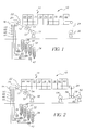
- FIG. 1 there is shown a schematic of an exemplary and well known coating and drying system 10 suitable for practicing the method of the present invention.
- the coating and drying system 10 is typically used to apply very thin films to a moving substrate 12 and to subsequently remove solvent in a dryer 14.
- a single coating apparatus 16 is shown such that system 10 has only one coating application point and only one dryer 14, but two or three (even as many as six) additional coating application points with corresponding drying sections are known in the fabrication of composite thin films.
- the process of sequential application and drying is known in the art as a tandem coating operation.
- Coating and drying apparatus 10 includes an unwinding station 18 to feed the moving substrate 12 around a back-up roller 20 where the coating is applied by coating apparatus 16.
- the coated web 22 then proceeds through the dryer 14.
- the final dry film 24 comprising a sulfone resin film on substrate 12 is wound into rolls at a wind-up station 26.
- coating and drying system 10 may also include electrical discharge devices, such as corona or glow discharge device 52, or polar charge assist device 54, to modify the substrate 12 prior to application of the coating.
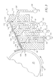
- FIG. 2 there is shown a schematic of the same exemplary coating and drying system 10 depicted in Figure 1 with an alternative winding operation. Accordingly, the drawings are numbered identically up to the winding operation.
- the dry film 24 comprising a substrate (which may be a resin film, paper, resin coated paper or metal) with a sulfone coating applied thereto is taken between opposing rollers 56, 58.
- the sulfone film 60 is peeled from substrate 12 with the sulfone film going to winding station 62 and the substrate 12 going to winding station 64.
- polyethylene phthalate (PET) is used as the substrate 12.
- PET polyethylene phthalate
- the substrate 12 may be pretreated with a subbing layer to enhance adhesion of the coated film 60 to the substrate 12.
- the coating apparatus 16 used to deliver coating fluids to the moving substrate 12 may be a multi-layer applicator such as a slide bead hopper, as taught for example in U. S. Patent no. 2,761,791 to Russell, or a slide curtain hopper, as taught by U. S. Patent no. 3,508,947 to Hughes.
- the coating apparatus 16 may be a single layer applicator, such as a slot die hopper or a jet hopper.
- the application device 16 is a multi-layer slide bead hopper.
- coating and drying system 10 includes a dryer 14 that will typically be a drying oven to remove solvent from the coated film.
- An exemplary dryer 14 used in the practice of the method of the present invention includes a first drying section 66 followed by eight additional drying sections 68-82 capable of independent control of temperature and air flow.
- dryer 14 is shown as having nine independent drying sections, drying ovens with fewer compartments are well known and may be used to practice the method of the present invention.
- the dryer 14 has at least two independent drying zones or sections.
- each of drying sections 68 - 82 each has independent temperature and airflow controls.
- temperature may be adjusted between 5°C and 150°C.
- optimum drying rates are needed in the early sections of dryer 14.
- fogging or blush of sulfone films is observed when the temperature in zones 66, 68 and 70 are set at 25 °C. This blush defect is particularly problematic when high vapor pressures solvents (methylene chloride and acetone) are used in the coating fluids.
- the first drying section 66 is operated at a temperature of at least about 25 °C but less than 95 °C with no direct air impingement on the wet coating of the coated web 22.
- drying sections 68 and 70 are also operated at a temperature of at least about 25°C but less than 95 °C. It is preferred that initial drying sections 66, 68 be operated at temperatures between about 30°C and about 60°C. It is most preferred that initial drying sections 66, 68 be operated at temperatures between about 30°C and about 50°C. The actual drying temperature in drying sections 66, 68 may optimized empirically within these ranges by those skilled in the art.
- Coating apparatus 16 schematically shown in side elevational cross-section, includes a front section 92, a second section 94, a third section 96, a fourth section 98, and a back plate 100.
- There is an inlet 118 into fourth section 98 for supplying coating liquid to metering slot 120 via pump 122 to form layer 124.
- Each slot 104, 112, 120, 128 includes a transverse distribution cavity.
- Front section 92 includes an inclined slide surface 134, and a coating lip 136.
- Back plate 100 extends above inclined slide surface 142 to form a back land surface 144. Residing adjacent the coating apparatus or hopper 16 is a coating backing roller 20 about which a web 12 is conveyed.
- Coating layers 108, 116, 124, 132 form a multi-layer composite which forms a coating bead 146 between lip 136 and substrate 12.
- the coating hopper 16 is movable from a non-coating position toward the coating backing roller 20 and into a coating position.
- coating apparatus 16 is shown as having four metering slots, coating dies having a larger number of metering slots (as many as nine or more) are well known and may be used to practice the method of the present invention.
- the coating fluids are comprised principally of a sulfone resin dissolved in an organic solvent.
- Polymers of the sulfone type are available in a variety of molecular weights as well as a variety of molecular structures. Common constituents of all sulfone resins are the presence of sulfone linkages (SO 2 ) and normally stabilizing aromatic groups in the polymer backbone.
- SO 2 sulfone linkages
- PAS Polyarylsulfones
- PES sulfones have remarkable thermal stability for a thermoplastic polymer with a glass transition temperature (T g ) approaching 225°C and a continuous use temperature of 200°C.
- T g glass transition temperature
- PSU sulfones While noted for their good transparency, PSU sulfones have a notably lower T g and continuous service temperature, of 185°C and 175°C, respectively.
- PSU is formed by reacting bisphenol A with 4,4'-dichlorodiphenylsulfone.
- PAS sulfones are actually a family of poly(diphenyl sulfone-diphenylene oxide sulfone) copolymer with T g and service temperatures intermediate between PES and PSU. Sulfones are commercially available from Amoco and BASF among others.
- suitable sovlents include, for example, chlorinated solvents (methylene chloride and 1,2 dichloroethane), alcohols (methanol, ethanol, n-propanol, isopropanol, n-butanol, isobutanol, diacetone alcohol, phenol, and cyclohexanol), ketones (acetone, methylethyl ketone, methylisobutyl ketone, and cyclohexanone), esters (methyl acetate, ethyl acetate, n-propyl acetate, isopropyl acetate, isobutyl acetate, and n-butyl acetate), aromatics (toluene and xylenes) and ethers (anisole, tetrahydrofuran, 1,3-dioxolane, 1,2-dioxolane, 1,3-dioxane, 1,
- sulfone solutions are prepared with a blend of the aforementioned solvents.
- Preferred primary solvents include methylene chloride, anisole, tetrahydrofuran and 1,3-dioxolane.
- Preferred co-solvents include ethyl acetate, methylethyl ketone, and isopropanol.
- Coating fluids may also contain plasticizers.
- Appropriate plasticizers for sulfone films include phthalate esters (dimethylphthalate, diethylphthalate, dibutylphthalate, dioctylphthalate, didecylphthalate and butyl octylphthalate), adipate esters (dioctyl adipate), and phosphate esters (tricresyl phosphate and triphenyl phosphate).
- Plasticizers are normally used to improve the physical and mechanical properties of the final film. In particular, plasticizers are known to improve flexibility.
- plasticizers may also be used here as coating aids in the converting operation to minimize premature film solidification at the coating hopper and to improve drying characteristics of the wet film.
- plasticizers may be used to minimize blistering, curl and delamination of sulfone films during the drying operation.
- plasticizers are added to the coating fluid at a total concentration of up to 25% by weight relative to the concentration of polymer in order to mitigate defects in the final sulfone film.
- Coating fluids may also contain surfactants as coating aids to control artifacts related to flow after coating.
- Artifacts created by flow after coating phenomena include mottle, repellencies, orange-peel (Bernard cells), and edge-withdraw.
- Surfactants used control flow after coating artifacts include siloxane and fluorochemical compounds.
- Examples of commercially available surfactants of the siloxane type include: 1.) Polydimethylsiloxanes such as DC200 Fluid from Dow Corning, 2.) Poly(dimethyl, methylphenyl)siloxanes such as DC510 Fluid from Dow Corning, and 3.) Polyalkyl substituted polydimethysiloxanes such as DC190 and DC1248 from Dow Corning as well as the L7000 Silwet series (L7000, L7001, L7004 and L7230) from Union Carbide, and 4.) Polyalkyl substituted poly(dimethyl, methylphenyl)siloxanes such as SF1023 from General Electric.
- fluorochemical surfactants examples include: 1.) Fluorinated alkyl esters such as the Fluorad series (FC430 and FC431) from the 3M Corporation, 2.) Fluorinated polyoxyethylene ethers such as the Zonyl series (FSN, FSN100, FSO, FSO100) from Du Pont, 3.) Acrylate:polyperfluoroalkyl ethylacrylates such as the F series (F270 and F600) from NOF Corporation, and 4.) Perfluoroalkyl derivatives such as the Surflon series (S383, S393, and S8405) from the Asahi Glass Company.
- surfactants are generally of the non-ionic type.
- non-ionic compounds of either the siloxane or fluorinated type are added to the uppermost layers.
- surfactants are most effective when present in the uppermost layers of the multi-layer coating.
- the concentration of surfactant is preferably 0.001 - 1.000 % by weight and most preferably 0.010 - 0.500 %.
- lesser amounts of surfactant may be used in the second uppermost layer to minimize diffusion of surfactant into the lowermost layers.
- the concentration of surfactant in the second uppermost layer is preferably 0.000 - 0.200 % by weight and most preferably between 0.000-0.100 % by weight. Because surfactants are only necessary in the uppermost layers, the overall amount of surfactant remaining in the final dried film is small.
- surfactants are not required to practice the method of the current invention, surfactants do improve the uniformity of the coated film.
- mottle nonuniformities are reduced by the use of surfactants.
- organic dyes may be added to the uppermost layer to add color to the coated film. For these dyed films, nonuniformities are easy to see and quantify. In this way, effective surfactant types and levels may be selected for optimum film uniformity.
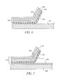
- FIGs 4 through 7 there are presented cross-sectional illustrations showing various film configurations prepared by the method of the present invention.
- a single-layer sulfone film 150 is shown partially peeled from a carrier substrate 152.
- Sulfone film 150 may be formed either by applying a single liquid layer to the carrier substrate 152 or by applying a multiple layer composite having a composition that is substantially the same among the layers.
- the carrier substrate 154 may have been pretreated with a subbing layer 156 that modifies the adhesive force between the single layer sulfone film 158 and the substrate 154.
- Figure 6 illustrates a multiple layer film 160 that is comprised of four compositionally discrete layers including a lowermost layer 162 nearest to the carrier support 170, two intermediate layers 164, 166, and an uppermost layer 168.
- Figure 6 also shows that the entire multiple layer composite 160 may be peeled from the carrier substrate 170.
- Figure 7 shows a multiple layer composite film 172 comprising a lowermost layer 174 nearest to the carrier substrate 182, two intermediate layers 176, 178, and an uppermost layer 180 being peeled from the carrier substrate 182.
- the carrier substrate 182 has been treated with a subbing layer 184 to modify the adhesion between the composite film 172 and substrate 182.
- Subbing layers 156 and 184 may be comprised of a number of polymeric materials such as polyvinylbutyrals, cellulosics, polyacrylates, polycarbonates gelatin and poly(acrylonitrile-co-vinylidene chloride-co-acrylic acid).
- polymeric materials such as polyvinylbutyrals, cellulosics, polyacrylates, polycarbonates gelatin and poly(acrylonitrile-co-vinylidene chloride-co-acrylic acid).
- the choice of materials used in the subbing layer may be optimized empirically by those skilled in the art.
- the method of the present invention may also include the step of coating over a previously prepared composite of sulfone film and carrier substrate.
- the coating and drying system 10 shown in Figures 1 and 2 may be used to apply a second multi-layer film to an existing sulfone film/substrate composite. If the film/substrate composite is wound into rolls before applying the subsequent coating, the process is called a multi-pass coating operation. If coating and drying operations are carried out sequentially on a machine with multiple coating stations and drying ovens, then the process is called a tandem coating operation. In this way, thick films may be prepared at high line speeds without the problems associated with the removal of large amounts of solvent from a very thick wet film. Moreover, the practice of multi-pass or tandem coating also has the advantage of minimizing other artifacts such as streak severity, mottle severity, and overall film nonuniformity.
- tandem coating or multi-pass coating requires some minimal level of adhesion between the first-pass film and the carrier substrate.
- film/substrate composites having poor adhesion are observed to blister after application of a second or third wet coating in a multi-pass operation.
- adhesion must be greater than 0.3 N/m between the first-pass sulfone film and the carrier substrate. This level of adhesion may be attained by a variety of web treatments including various subbing layers and various electronic discharge treatments.
- excessive adhesion between the applied film and substrate is also undesirable since the film may be damaged during subsequent peeling operations.
- film/substrate composites having an adhesive force of greater than 250 N/m have been found to peel poorly.
- the adhesion between the sulfone film and the carrier substrate is less than 250 N/m. Most preferably, the adhesion between polycarbonate film and the carrier substrate is between 0.5 and 25 N/m.
- the method of the present invention is suitable for application of sulfone resin coatings to a variety of substrates such as polyethylene terephthalate (PET), polyethylene naphthalate (PEN), polycarbonate, polystyrene, and other polymeric films.
- Additional substrates may include paper, laminates of paper and polymeric films, glass, cloth, aluminum and other metal supports.
- substrates may be pretreated with subbing layers or electrical discharge devices.
- Substrates may also be pretreated with functional layers containing various binders and addenda.
- a viscous polymeric dope is delivered through a feed line 200 to an extrusion hopper 202 from a pressurized tank 204 by a pump 206.
- the dope is cast onto a highly polished metal drum 208 located within a first drying section 210 of the drying oven 212.
- the cast film 214 is allowed to partially dry on the moving drum 208 and is then peeled from the drum 208.
- the cast film 214 is then conveyed to a final drying section 216 to remove the remaining solvent.
- the final dried film 218 is then wound into rolls at a wind-up station 220.
- the prior art cast film typically has a thickness in the range of from 40 to 200 ⁇ m.
- Coating methods are distinguished from casting methods by the process steps necessary for each technology. These process steps in turn affect a number of tangibles such as fluid viscosity, converting aids, substrates, and hardware that are unique to each method.
- coating methods involve application of dilute low viscosity liquids to thin flexible substrates, evaporating the solvent in a drying oven, and winding the dried film/substrate composite into rolls.
- casting methods involve applying a concentrated viscous dope to a highly polished metal drum or band, partially drying the wet film on the metal substrate, stripping the partially dried film from the substrate, removing additional solvent from the partially dried film in a drying oven, and winding the dried film into rolls.
- coating methods require very low viscosity liquids of less than 5,000 cp.
- the viscosity of the coated liquids will generally be less than 2000 cp and most often less than 1500 cp.
- the viscosity of the lowermost layer is preferred to be less than 200 cp. and most preferably less than 100 cp. for high speed coating application.
- casting methods require highly concentrated dopes with viscosity on the order of 10,000-100,000 cp for practical operating speeds.
- coating methods generally involve the use of surfactants as converting aids to control flow after coating artifacts such as mottle, repellencies, orange peel, and edge withdraw.
- casting methods do not require surfactants.
- converting aids are only used to assist in the stripping operation in casting methods.
- n-butanol and water are sometimes used as a converting aid in casting sulfone films to facilitate stripping of the sulfone film from the metal drum.
- coating methods generally utilize thin (10-250 micron) flexible supports.
- casting methods employ thick (1-100 mm), continuous, highly polished metal drums or rigid bands.
- the sulfone polymer was the polyethersulfone type (PES) with a weight average molecular weight of 32,000 daltons.
- This example describes the single pass formation of a very thin sulfone film.
- the coating apparatus 16 illustrated in Figure 1 was used to apply four liquid layers to a moving substrate 12, 170 of untreated polyethylene terephthalate (PET) to form a single layer film as illustrated earlier in Figure 6.
- the substrate speed was 25 cm/s.
- All coating fluids were comprised of PES dissolved in 1,3-dioxolane.
- the lowermost layer 162 had a viscosity of 20 cp. and a wet thickness of 11 ⁇ m on the moving substrate 170.
- the second 164 and third 166 layers each had a viscosity of 195 cp. and had a combined final wet thickness of 34 ⁇ m on the moving substrate 170.
- the third layer 166 also contained a fluorinated surfactant (Surflon S8405) at concentration of 0.01 %.
- the uppermost layer 168 had a viscosity of 80 cp. and a wet thickness of 22 ⁇ m on the moving substrate 170.
- the uppermost layer 168 also contained a fluorinated surfactant (Surflon S8405) at a weight percent of 0.20%. Coatings were applied at a temperature of 24°C.
- the gap between the coating lip 136 and the moving substrate 12 (see Figure 3) was 200 ⁇ m.
- the pressure differential across the coating bead 146 was adjusted between 0-10 cm of water to establish a uniform coating.
- the temperature in the drying sections 66 and 68 was 40°C.
- the temperature in the drying section 70 was 50°C.
- the temperature in the drying sections 72, 74, 76, 78, 80 was 95°C.
- the temperature in the drying section 82 was 25°C.
- the composite of PES film and PET substrate was wound into rolls. When peeled from the untreated PET substrate, the final dry film had a thickness of 10 ⁇ m.
- the peeled PES film had a good appearance, was smooth, was free from wrinkles and cockle artifacts, and had an in-plane retardation of less than 2.0 nm. Properties of this sulfone film are summarized in Table I.
- This example describes the single pass formation of a thin PES film.
- the conditions were identical to those described in Example 1 except that the combined wet thickness of the second and third layers 164 and 166 was increased to 94 ⁇ m.
- the composite of PES film and PET substrate was wound into rolls. When peeled from the subbed PET substrate, the final dry film had a thickness of 20 ⁇ m.
- the peeled PES film had a good appearance, was smooth, was free from wrinkles and cockle artifacts, and had an in-plane retardation of less than 2.0 nm. Properties of this PES film are summarized in Table I.
- This example describes the single pass formation of a thin PES film.
- the conditions were identical to those described in Example 1 except that the combined wet thickness of the second and third layers 164 and 166 was increased to 153 ⁇ m.
- the composite of PES film and PET substrate was wound into rolls. When peeled from the subbed PET substrate, the final dry film had a thickness of 30 ⁇ m.
- the PES film had a good appearance, was smooth, was free from wrinkles and cockle artifacts, and had an in-plane retardation of less than 2.0 nm. Properties of this PES film are summarized in Table I.
- This example describes the single pass formation a PES film.
- the conditions were identical to those described in Example 3 except that the combined wet thickness of the second and third layers 164 and 166 was increased to 211 ⁇ m.
- the composite of PES film and PET substrate was wound into rolls. When peeled from the subbed PET substrate, the final dry film had a thickness of 40 ⁇ m.
- the peeled PES film had a good appearance, was smooth, was free from wrinkles and cockle artifacts, and had an in-plane retardation of less than 3.0 nm. Properties of this PES film are summarized in Table I.
- This example describes the formation of a PES film using a three-pass coating operation.
- the conditions were identical to those described in Example 2 except that the wound composite of PES film and PET substrate of Example 2 was subsequently over-coated with two additional passes. Each additional pass was conducted with the combined wet thickness of the second and third layers at 211 ⁇ m as described in Example 4.
- the final composite of PES film and PET substrate was wound into rolls.
- the final dry film had a thickness of 100 ⁇ m.
- the peeled PES film was smooth, was free from wrinkles and cockle artifacts, and had an in-plane retardation of less than 2.0 nm. Properties of this PES film are summarized in Table I.
- This example describes the formation of a PES:PET composite having poor peeling properties.
- the PET support has a subbing layer of poly(acrylonitrile-co-vinylidene chloride-co-acrylic acid).
- the conditions for Comparative Example 1 were identical to those described in Example 1.
- the final dry film had a thickness of 10 ⁇ m.
- the PES film could not be peeled from the subbed PET substrate.
- the adhesive force of the PES film to the subbed PET substrate was found to be greater than 250 N/m.
- This example describes defects formed as a result of poor drying conditions during a single pass operation.
- the conditions for Comparative Example 4 were identical to those described in Comparative Example 1 except that the drying conditions were adjusted such that the temperature in the first three drying zones 66, 68, 70 was increased to 95°C.
- the final dry film had a thickness of 10 ⁇ m.
- the peeled PES film was of unacceptable quality due to a reticulation pattern in the film as well as to blister artifacts.
- Example Thickness Retardation Transmittance Haze 10 ⁇ m 1.2nm 90.8% 0.2% 0.7nm 2 20 1.0 90.9 0.3 0.6 3 30 1.6 90.7 0.2 0.7 4 40 2.6 90.4 0.2 0.7 5 100 1.8 90.4 0.4 1.2
- Thickness of the final peeled film was measured in microns using a Model EG-225 gauge from the Ono Sokki Company.
- In-plane retardation (R e ) of peeled films were determined in nanometers (nm) using a Woollam M-2000V Spectroscopic Ellipsometer at wavelengths from 370 to 1000 nm. In-plane retardation values in Table I are computed for measurements taken at 590 nm.
- R e is the in-plane retardation at 590 nm
- n x is the index of refraction of the peeled film in the slow axis direction
- n y is the is the index of refraction of the peeled film in the fast axis direction
- d is the thickness of the peeled film in nanometers (nm).
- R e is the absolute value of the difference in birefringence between the slow axis direction and the fast axis direction in the plane of the peeled film multiplied by the thickness of the film.
- Transmittance and Haze are measured using the Haze-Gard Plus (Model HB-4725) from BYK-Gardner. Total transmittance is all the light energy transmitted through the film as absorbed on an integrating sphere. Transmitted haze is all light energy scattered beyond 2.5° as absorbed on an integrating sphere.
- Surface roughness was determined in nanometers (nm) by scanning probe microscopy using TappingModeTM Atomic Force Microscopy (Model D300 from Digital Instruments).
- Adhesion The adhesion strength of the coated samples was measured in Newtons per meter (N/m) using a modified 180° peel test with an Instron 1122 Tensile Tester with a 500 gram load cell. First, 0.0254 m (one inch) wide strips of the coated sample were prepared. Delamination of the coating at one end was initiated using a piece of 3M Magic Tape. An additional piece of tape was then attached to the delaminated part of the coating and served as the gripping point for testing. The extending tape was long enough to extend beyond the support such that the Instron grips did not interfere with the testing.
- Residual Solvent A qualitative assessment of residual solvents remaining in a dried film is done by first peeling the film from the carrier substrate, weighing the peeled film, incubating the film in an oven at 100 °C for 16 hours, and finally weighing the incubated film. Residual solvent is expressed as percentage of the weight difference divided by the post-incubation weight.
Landscapes
- Engineering & Computer Science (AREA)
- Chemical & Material Sciences (AREA)
- Mechanical Engineering (AREA)
- Chemical Kinetics & Catalysis (AREA)
- Medicinal Chemistry (AREA)
- Polymers & Plastics (AREA)
- Organic Chemistry (AREA)
- Health & Medical Sciences (AREA)
- Physics & Mathematics (AREA)
- Manufacturing & Machinery (AREA)
- Optics & Photonics (AREA)
- General Physics & Mathematics (AREA)
- Materials Engineering (AREA)
- Moulding By Coating Moulds (AREA)
- Polarising Elements (AREA)
- Application Of Or Painting With Fluid Materials (AREA)
- Laminated Bodies (AREA)
- Manufacture Of Macromolecular Shaped Articles (AREA)
Applications Claiming Priority (4)
| Application Number | Priority Date | Filing Date | Title |
|---|---|---|---|
| US38193102P | 2002-05-20 | 2002-05-20 | |
| US381931P | 2002-05-20 | ||
| US10/190,390 US20030215583A1 (en) | 2002-05-20 | 2002-07-03 | Sulfone films prepared by coating methods |
| US190390 | 2002-07-03 |
Publications (2)
| Publication Number | Publication Date |
|---|---|
| EP1384744A2 true EP1384744A2 (de) | 2004-01-28 |
| EP1384744A3 EP1384744A3 (de) | 2004-02-04 |
Family
ID=29423133
Family Applications (1)
| Application Number | Title | Priority Date | Filing Date |
|---|---|---|---|
| EP03076361A Withdrawn EP1384744A3 (de) | 2002-05-20 | 2003-05-08 | Aus Beschichtungsverfahren hergestellte Polysulfonfolien |
Country Status (3)
| Country | Link |
|---|---|
| US (2) | US20030215583A1 (de) |
| EP (1) | EP1384744A3 (de) |
| JP (1) | JP2003342390A (de) |
Families Citing this family (16)
| Publication number | Priority date | Publication date | Assignee | Title |
|---|---|---|---|---|
| US7163738B2 (en) * | 2002-05-20 | 2007-01-16 | Eastman Kodak Company | Polyvinyl alcohol films prepared by coating methods |
| US20030215581A1 (en) * | 2002-05-20 | 2003-11-20 | Eastman Kodak Company | Polycarbonate films prepared by coating methods |
| US7048823B2 (en) * | 2002-05-20 | 2006-05-23 | Eastman Kodak Company | Acrylic films prepared by coating methods |
| US7012746B2 (en) * | 2002-05-20 | 2006-03-14 | Eastman Kodak Company | Polyvinyl butyral films prepared by coating methods |
| US20030215582A1 (en) * | 2002-05-20 | 2003-11-20 | Eastman Kodak Company | Optical films prepared by coating methods |
| US7083752B2 (en) * | 2002-05-20 | 2006-08-01 | Eastman Kodak Company | Cellulose acetate films prepared by coating methods |
| US7125504B2 (en) * | 2002-11-13 | 2006-10-24 | Eastman Kodak Company | Optical switch microfilms |
| US7279060B2 (en) * | 2004-05-04 | 2007-10-09 | Eastman Kodak Company | Guarded cover film for LCD polarizers |
| US7252733B2 (en) * | 2004-05-04 | 2007-08-07 | Eastman Kodak Company | Polarizer guarded cover sheet with adhesion promoter |
| WO2006064700A1 (ja) * | 2004-12-17 | 2006-06-22 | Kaneka Corporation | ポリイミド多層接着フィルムおよびその製造方法 |
| JP2006291056A (ja) * | 2005-04-12 | 2006-10-26 | Daicel Chem Ind Ltd | ポリスルホン系樹脂溶液組成物、それを用いた積層体及びポリスルホン系樹脂フィルム |
| US7622185B2 (en) * | 2005-04-15 | 2009-11-24 | Nitto Denko Corporation | Protective cover sheet comprising a UV-absorbing layer for a polarizer plate and method of making the same |
| US7662456B2 (en) * | 2005-12-12 | 2010-02-16 | Eastman Kodak Company | Guarded cover sheet for LCD polarizers and method of making the same |
| US7655289B2 (en) * | 2005-12-12 | 2010-02-02 | Eastman Kodak Company | Optical film composite having spatially controlled adhesive strength |
| KR101343959B1 (ko) | 2012-09-19 | 2013-12-24 | 한국기계연구원 | 통합 코팅 장치 |
| TWI586533B (zh) | 2013-12-25 | 2017-06-11 | 日東電工股份有限公司 | 偏光板及偏光板之製造方法 |
Family Cites Families (63)
| Publication number | Priority date | Publication date | Assignee | Title |
|---|---|---|---|---|
| US2173304A (en) * | 1939-05-04 | 1939-09-19 | Polaroid Corp | Light polarizer |
| US2237567A (en) * | 1939-05-04 | 1941-04-08 | Polaroid Corp | Light polarizer and process of manufacturing the same |
| US2445555A (en) * | 1945-04-16 | 1948-07-20 | Polaroid Corp | Light-polarizing polyvinyl sheet containing polyvinyl compoundboric acid complex |
| CA557259A (en) * | 1955-02-23 | 1958-05-13 | Canadian Kodak Co. Limited | Multiple layer hopper for multiply coating a web |
| US3508947A (en) * | 1968-06-03 | 1970-04-28 | Eastman Kodak Co | Method for simultaneously applying a plurality of coated layers by forming a stable multilayer free-falling vertical curtain |
| US4113360A (en) * | 1977-03-28 | 1978-09-12 | Siemens Aktiengesellschaft | Indicating device for illustrating symbols of all kinds |
| US4348238A (en) * | 1980-06-26 | 1982-09-07 | Eastman Kodak Company | Manufacture of cellulose ester film |
| DE3129162C2 (de) * | 1980-07-31 | 1983-10-20 | Nitto Electric Industrial Co., Ltd., Ibaraki, Osaka | Polarisierender Film |
| US4327121A (en) * | 1980-10-02 | 1982-04-27 | Scott Paper Company | Release coatings |
| DE3238905C2 (de) * | 1982-10-21 | 1986-01-23 | Agfa-Gevaert Ag, 5090 Leverkusen | Verfahren zur Mehrfachbeschichtung von bewegten Gegenständen oder Bahnen |
| DE3238904A1 (de) * | 1982-10-21 | 1984-04-26 | Agfa-Gevaert Ag, 5090 Leverkusen | Verfahren zur mehrfachbeschichtung von bewegten bahnen |
| JPS59202261A (ja) * | 1983-04-30 | 1984-11-16 | Nippon Oil & Fats Co Ltd | 高分子材料の表面改質法 |
| US4617207A (en) * | 1983-08-15 | 1986-10-14 | Mitsui Toatsu Chemicals, Incorporated | Thermoplastic resin sheet |
| US4664859A (en) * | 1983-12-02 | 1987-05-12 | Vcf Films Inc. Div. Of Pmc | Process for solvent casting a film |
| US4584231A (en) * | 1983-12-02 | 1986-04-22 | Vcf Packaging Films, Inc. | Solvent cast acrylic film |
| JPS615986A (ja) * | 1984-06-20 | 1986-01-11 | Mitsui Toatsu Chem Inc | 光記録媒体 |
| US4591512A (en) * | 1985-01-25 | 1986-05-27 | Polaroid Corporation | Method of making light polarizer |
| US4818624A (en) * | 1986-12-19 | 1989-04-04 | Polaroid Corporation, Patent Department | Stabilized light-polarizing material |
| US4895769A (en) * | 1988-08-09 | 1990-01-23 | Polaroid Corporation | Method for preparing light polarizer |
| US4913760A (en) * | 1988-08-29 | 1990-04-03 | Eastman Kodak Company | Method of manufacturing a dried, thermoformable, paint-coated sheet material having gloss and smoothness |
| US4952457A (en) * | 1988-12-05 | 1990-08-28 | Monsanto Company | Laminated safety glass and polymeric laminate for use therein |
| US5250383A (en) * | 1990-02-23 | 1993-10-05 | Fuji Photo Film Co., Ltd. | Process for forming multilayer coating |
| US5219510A (en) * | 1990-09-26 | 1993-06-15 | Eastman Kodak Company | Method of manufacture of cellulose ester film |
| AU652220B2 (en) * | 1991-02-15 | 1994-08-18 | Toray Industries, Inc. | Plastic optical articles |
| SG54990A1 (en) * | 1991-12-09 | 1998-12-21 | Sumitomo Chemical Co | Process for producing phase retarder from a thermoplastic resin film or sheet |
| US5256357A (en) * | 1992-05-28 | 1993-10-26 | Eastman Kodak Company | Apparatus and method for cocasting film layers |
| DE4324167A1 (de) * | 1993-07-19 | 1995-01-26 | Hoechst Ag | Polyvinylbutyralfolien mit verbesserten optischen Eigenschaften |
| US5478518A (en) * | 1993-10-04 | 1995-12-26 | Teijin Limited | Polycarbonate film for optical purposes and a production process thereof |
| US5695694A (en) * | 1993-10-08 | 1997-12-09 | Teijin Limited | Method of producing an acylated cellulose film |
| JPH07186163A (ja) * | 1993-12-28 | 1995-07-25 | Sekisui Chem Co Ltd | キャスティングフィルムの製造方法 |
| US5909314A (en) * | 1994-02-15 | 1999-06-01 | Dai Nippon Printing Co., Ltd. | Optical functional materials and process for producing the same |
| US5645766A (en) * | 1995-03-30 | 1997-07-08 | Teijin Limited | Film of aromatic polyethersulfone process for the production thereof and solution composition for the production thereof |
| EP0744433A1 (de) * | 1995-05-23 | 1996-11-27 | Sekisui Chemical Co., Ltd. | Verfahren zur Herstellung von einem Film aus Polysulfonharz und Verzögerungsschicht |
| JPH0952240A (ja) * | 1995-08-10 | 1997-02-25 | Sekisui Chem Co Ltd | 光学用透明フィルムの製造方法 |
| JPH0990333A (ja) * | 1995-09-26 | 1997-04-04 | Fuji Photo Film Co Ltd | 液晶表示装置 |
| JPH0996722A (ja) * | 1995-10-02 | 1997-04-08 | Fuji Photo Film Co Ltd | 偏光板保護膜 |
| US5771321A (en) * | 1996-01-04 | 1998-06-23 | Massachusetts Institute Of Technology | Micromechanical optical switch and flat panel display |
| US5743980A (en) * | 1996-05-02 | 1998-04-28 | Industrial Technology Research Institute | Method of fabricating an optical retardation film |
| TW336999B (en) * | 1996-07-03 | 1998-07-21 | Sumitomo Kagaku Kk | Phase retarder and liquid crystal display device using the same |
| WO1998003574A1 (fr) * | 1996-07-18 | 1998-01-29 | Asahi Glass Company Ltd. | Composes organosilicies fluores et leur procede de preparation |
| US5849363A (en) * | 1997-01-21 | 1998-12-15 | Minnesota Mining And Manufacturing Company | Apparatus and method for minimizing the drying of a coating fluid on a slide coater surface |
| US5925289A (en) * | 1997-06-20 | 1999-07-20 | Polaroid Corporation | Synthetic UV-bleached polarizer and method for the manufacture thereof |
| EP0992331A4 (de) * | 1997-06-23 | 2000-07-19 | Teijin Ltd | Optische folien und verfahren zu deren herstellung |
| US6649104B2 (en) * | 1997-07-31 | 2003-11-18 | Sumitomo Chemical Company, Limited | Acrylic resin film and laminated film comprising the same |
| US5925769A (en) * | 1997-09-09 | 1999-07-20 | Ortho Pharmaceutical, Corp. | Acetylenic 1,5-diarylpyrazoles as antiinflammatory agents |
| US5965321A (en) * | 1997-09-25 | 1999-10-12 | E. U. Du Pont De Nemours And Company | Peel-apart photosensitive elements and their process of use |
| US5973834A (en) * | 1997-12-19 | 1999-10-26 | Polaroid Corporation | Method for the manufacture of a light-polarizing polyvinylene sheet |
| DE69937429T2 (de) * | 1998-07-31 | 2008-08-21 | Merck Patent Gmbh | Verfahren zur Herstellung eines optischen Verzögerungsfilms |
| US6654085B1 (en) * | 1999-02-10 | 2003-11-25 | Kimoto Co., Ltd. | Front scattering film with a light scattering layer and a peelable substrate |
| US6245382B1 (en) * | 1999-02-24 | 2001-06-12 | Datacard, Inc. | Method for making protective film |
| TWI225499B (en) * | 1999-04-15 | 2004-12-21 | Konishiroku Photo Ind | Protective film for polarizing plate |
| JP3515426B2 (ja) * | 1999-05-28 | 2004-04-05 | 大日本印刷株式会社 | 防眩フィルムおよびその製造方法 |
| JP4336427B2 (ja) * | 1999-10-01 | 2009-09-30 | 帝人株式会社 | 表面保護フィルムおよびそれからなる積層体 |
| DE60108550T2 (de) * | 2000-05-02 | 2006-01-12 | KURARAY CO., LTD, Kurashiki | Polymerfolie aus Polyvinylalkohol, Verfahren zu ihrer Herstellung und Polarisationsfolie |
| TWI230275B (en) * | 2000-05-12 | 2005-04-01 | Kuraray Co | Polyvinyl alcohol film and polarization film |
| US6965473B2 (en) * | 2001-02-07 | 2005-11-15 | Sumitomo Chemical Company, Limited | Polarizing plate and liquid crystal display device using the same |
| JP2003326864A (ja) * | 2002-05-16 | 2003-11-19 | Fuji Photo Film Co Ltd | 画像形成材料及び画像形成方法 |
| US20030215581A1 (en) * | 2002-05-20 | 2003-11-20 | Eastman Kodak Company | Polycarbonate films prepared by coating methods |
| US7163738B2 (en) * | 2002-05-20 | 2007-01-16 | Eastman Kodak Company | Polyvinyl alcohol films prepared by coating methods |
| US7048823B2 (en) * | 2002-05-20 | 2006-05-23 | Eastman Kodak Company | Acrylic films prepared by coating methods |
| US20030215582A1 (en) * | 2002-05-20 | 2003-11-20 | Eastman Kodak Company | Optical films prepared by coating methods |
| US7083752B2 (en) * | 2002-05-20 | 2006-08-01 | Eastman Kodak Company | Cellulose acetate films prepared by coating methods |
| US7012746B2 (en) * | 2002-05-20 | 2006-03-14 | Eastman Kodak Company | Polyvinyl butyral films prepared by coating methods |
-
2002
- 2002-07-03 US US10/190,390 patent/US20030215583A1/en not_active Abandoned
-
2003
- 2003-05-08 EP EP03076361A patent/EP1384744A3/de not_active Withdrawn
- 2003-05-20 JP JP2003142028A patent/JP2003342390A/ja active Pending
-
2006
- 2006-02-13 US US11/352,567 patent/US20060127608A1/en not_active Abandoned
Also Published As
| Publication number | Publication date |
|---|---|
| JP2003342390A (ja) | 2003-12-03 |
| EP1384744A3 (de) | 2004-02-04 |
| US20030215583A1 (en) | 2003-11-20 |
| US20060127608A1 (en) | 2006-06-15 |
Similar Documents
| Publication | Publication Date | Title |
|---|---|---|
| US7012746B2 (en) | Polyvinyl butyral films prepared by coating methods | |
| US7083752B2 (en) | Cellulose acetate films prepared by coating methods | |
| EP1367083A2 (de) | Aus Beschichtungsverfahren hergestellte optische Folien | |
| US7163738B2 (en) | Polyvinyl alcohol films prepared by coating methods | |
| US7048823B2 (en) | Acrylic films prepared by coating methods | |
| US7686987B2 (en) | Polycarbonate films prepared by coating methods | |
| US7655289B2 (en) | Optical film composite having spatially controlled adhesive strength | |
| US20060068128A1 (en) | Optical films and process for making them | |
| US7252733B2 (en) | Polarizer guarded cover sheet with adhesion promoter | |
| EP1384744A2 (de) | Aus Beschichtungsverfahren hergestellte Polysulfonfolien | |
| US20070134477A1 (en) | Guarded cover sheet for LCD polarizers and method of making the same | |
| US7125504B2 (en) | Optical switch microfilms | |
| CN1330689C (zh) | 光开关微膜 |
Legal Events
| Date | Code | Title | Description |
|---|---|---|---|
| PUAI | Public reference made under article 153(3) epc to a published international application that has entered the european phase |
Free format text: ORIGINAL CODE: 0009012 |
|
| PUAL | Search report despatched |
Free format text: ORIGINAL CODE: 0009013 |
|
| AK | Designated contracting states |
Kind code of ref document: A2 Designated state(s): AT BE BG CH CY CZ DE DK EE ES FI FR GB GR HU IE IT LI LU MC NL PT RO SE SI SK TR |
|
| AX | Request for extension of the european patent |
Extension state: AL LT LV MK |
|
| AK | Designated contracting states |
Kind code of ref document: A3 Designated state(s): AT BE BG CH CY CZ DE DK EE ES FI FR GB GR HU IE IT LI LU MC NL PT RO SE SI SK TR |
|
| AX | Request for extension of the european patent |
Extension state: AL LT LV MK |
|
| AKX | Designation fees paid | ||
| REG | Reference to a national code |
Ref country code: DE Ref legal event code: 8566 |
|
| STAA | Information on the status of an ep patent application or granted ep patent |
Free format text: STATUS: THE APPLICATION IS DEEMED TO BE WITHDRAWN |
|
| 18D | Application deemed to be withdrawn |
Effective date: 20040805 |