EP1384502B1 - Mixer, heat exchanger - Google Patents
Mixer, heat exchanger Download PDFInfo
- Publication number
- EP1384502B1 EP1384502B1 EP03015959A EP03015959A EP1384502B1 EP 1384502 B1 EP1384502 B1 EP 1384502B1 EP 03015959 A EP03015959 A EP 03015959A EP 03015959 A EP03015959 A EP 03015959A EP 1384502 B1 EP1384502 B1 EP 1384502B1
- Authority
- EP
- European Patent Office
- Prior art keywords
- mixer
- heat exchanger
- tubes
- fins
- housing
- Prior art date
- Legal status (The legal status is an assumption and is not a legal conclusion. Google has not performed a legal analysis and makes no representation as to the accuracy of the status listed.)
- Expired - Lifetime
Links
- 230000003068 static effect Effects 0.000 claims abstract description 31
- 238000001816 cooling Methods 0.000 claims description 3
- 239000003054 catalyst Substances 0.000 claims description 2
- 230000006698 induction Effects 0.000 claims 1
- 239000000463 material Substances 0.000 abstract description 16
- 238000002156 mixing Methods 0.000 description 35
- 238000012546 transfer Methods 0.000 description 34
- 238000005496 tempering Methods 0.000 description 29
- 238000010438 heat treatment Methods 0.000 description 20
- 238000013461 design Methods 0.000 description 15
- 238000000034 method Methods 0.000 description 15
- 238000006243 chemical reaction Methods 0.000 description 14
- 230000008569 process Effects 0.000 description 13
- 230000000694 effects Effects 0.000 description 10
- 239000007788 liquid Substances 0.000 description 10
- 239000000126 substance Substances 0.000 description 10
- 239000010902 straw Substances 0.000 description 6
- 238000005266 casting Methods 0.000 description 5
- 230000007797 corrosion Effects 0.000 description 5
- 238000005260 corrosion Methods 0.000 description 5
- 239000011346 highly viscous material Substances 0.000 description 5
- 230000006872 improvement Effects 0.000 description 5
- 238000004519 manufacturing process Methods 0.000 description 5
- 238000012360 testing method Methods 0.000 description 5
- 230000008901 benefit Effects 0.000 description 4
- 238000010276 construction Methods 0.000 description 4
- 238000009826 distribution Methods 0.000 description 4
- 239000000155 melt Substances 0.000 description 4
- 229920000642 polymer Polymers 0.000 description 4
- 229910000679 solder Inorganic materials 0.000 description 4
- 238000005476 soldering Methods 0.000 description 4
- 239000011345 viscous material Substances 0.000 description 4
- 238000003466 welding Methods 0.000 description 4
- PXHVJJICTQNCMI-UHFFFAOYSA-N Nickel Chemical compound [Ni] PXHVJJICTQNCMI-UHFFFAOYSA-N 0.000 description 3
- 239000000654 additive Substances 0.000 description 3
- 238000004140 cleaning Methods 0.000 description 3
- 239000000975 dye Substances 0.000 description 3
- 238000012545 processing Methods 0.000 description 3
- 230000009471 action Effects 0.000 description 2
- 230000000996 additive effect Effects 0.000 description 2
- 239000012267 brine Substances 0.000 description 2
- 239000003795 chemical substances by application Substances 0.000 description 2
- 239000002826 coolant Substances 0.000 description 2
- 230000006378 damage Effects 0.000 description 2
- 238000005516 engineering process Methods 0.000 description 2
- 238000005242 forging Methods 0.000 description 2
- 239000012535 impurity Substances 0.000 description 2
- 230000000977 initiatory effect Effects 0.000 description 2
- 238000009434 installation Methods 0.000 description 2
- 238000000746 purification Methods 0.000 description 2
- 230000009467 reduction Effects 0.000 description 2
- 229920002545 silicone oil Polymers 0.000 description 2
- HPALAKNZSZLMCH-UHFFFAOYSA-M sodium;chloride;hydrate Chemical compound O.[Na+].[Cl-] HPALAKNZSZLMCH-UHFFFAOYSA-M 0.000 description 2
- 238000001228 spectrum Methods 0.000 description 2
- 238000009827 uniform distribution Methods 0.000 description 2
- XLYOFNOQVPJJNP-UHFFFAOYSA-N water Substances O XLYOFNOQVPJJNP-UHFFFAOYSA-N 0.000 description 2
- 229910000831 Steel Inorganic materials 0.000 description 1
- ATJFFYVFTNAWJD-UHFFFAOYSA-N Tin Chemical compound [Sn] ATJFFYVFTNAWJD-UHFFFAOYSA-N 0.000 description 1
- RTAQQCXQSZGOHL-UHFFFAOYSA-N Titanium Chemical compound [Ti] RTAQQCXQSZGOHL-UHFFFAOYSA-N 0.000 description 1
- HCHKCACWOHOZIP-UHFFFAOYSA-N Zinc Chemical compound [Zn] HCHKCACWOHOZIP-UHFFFAOYSA-N 0.000 description 1
- 230000006978 adaptation Effects 0.000 description 1
- 229910045601 alloy Inorganic materials 0.000 description 1
- 239000000956 alloy Substances 0.000 description 1
- 229910052782 aluminium Inorganic materials 0.000 description 1
- XAGFODPZIPBFFR-UHFFFAOYSA-N aluminium Chemical compound [Al] XAGFODPZIPBFFR-UHFFFAOYSA-N 0.000 description 1
- 230000015572 biosynthetic process Effects 0.000 description 1
- 238000009835 boiling Methods 0.000 description 1
- 230000008859 change Effects 0.000 description 1
- 238000001311 chemical methods and process Methods 0.000 description 1
- 239000012459 cleaning agent Substances 0.000 description 1
- 150000001875 compounds Chemical class 0.000 description 1
- 238000007599 discharging Methods 0.000 description 1
- 238000005485 electric heating Methods 0.000 description 1
- 238000011156 evaluation Methods 0.000 description 1
- 238000001704 evaporation Methods 0.000 description 1
- 230000008020 evaporation Effects 0.000 description 1
- 238000002474 experimental method Methods 0.000 description 1
- 244000144992 flock Species 0.000 description 1
- 230000017525 heat dissipation Effects 0.000 description 1
- 239000008141 laxative Substances 0.000 description 1
- 230000002475 laxative effect Effects 0.000 description 1
- 229910052751 metal Inorganic materials 0.000 description 1
- 239000002184 metal Substances 0.000 description 1
- 238000010327 methods by industry Methods 0.000 description 1
- 239000000203 mixture Substances 0.000 description 1
- 229910052759 nickel Inorganic materials 0.000 description 1
- 238000005192 partition Methods 0.000 description 1
- 239000010970 precious metal Substances 0.000 description 1
- 238000002360 preparation method Methods 0.000 description 1
- 230000002035 prolonged effect Effects 0.000 description 1
- 239000000376 reactant Substances 0.000 description 1
- 239000003507 refrigerant Substances 0.000 description 1
- 230000001105 regulatory effect Effects 0.000 description 1
- 238000000926 separation method Methods 0.000 description 1
- 239000010935 stainless steel Substances 0.000 description 1
- 229910001220 stainless steel Inorganic materials 0.000 description 1
- 239000010959 steel Substances 0.000 description 1
- 230000003685 thermal hair damage Effects 0.000 description 1
- 229920001169 thermoplastic Polymers 0.000 description 1
- 239000004416 thermosoftening plastic Substances 0.000 description 1
- 239000010936 titanium Substances 0.000 description 1
- 229910052719 titanium Inorganic materials 0.000 description 1
- 229910052725 zinc Inorganic materials 0.000 description 1
- 239000011701 zinc Substances 0.000 description 1
Images

Classifications
-
- B—PERFORMING OPERATIONS; TRANSPORTING
- B01—PHYSICAL OR CHEMICAL PROCESSES OR APPARATUS IN GENERAL
- B01F—MIXING, e.g. DISSOLVING, EMULSIFYING OR DISPERSING
- B01F35/00—Accessories for mixers; Auxiliary operations or auxiliary devices; Parts or details of general application
- B01F35/90—Heating or cooling systems
- B01F35/93—Heating or cooling systems arranged inside the receptacle
-
- F—MECHANICAL ENGINEERING; LIGHTING; HEATING; WEAPONS; BLASTING
- F28—HEAT EXCHANGE IN GENERAL
- F28D—HEAT-EXCHANGE APPARATUS, NOT PROVIDED FOR IN ANOTHER SUBCLASS, IN WHICH THE HEAT-EXCHANGE MEDIA DO NOT COME INTO DIRECT CONTACT
- F28D7/00—Heat-exchange apparatus having stationary tubular conduit assemblies for both heat-exchange media, the media being in contact with different sides of a conduit wall
- F28D7/0058—Heat-exchange apparatus having stationary tubular conduit assemblies for both heat-exchange media, the media being in contact with different sides of a conduit wall the conduits for only one medium being tubes having different orientations to each other or crossing the conduit for the other heat exchange medium
-
- B—PERFORMING OPERATIONS; TRANSPORTING
- B01—PHYSICAL OR CHEMICAL PROCESSES OR APPARATUS IN GENERAL
- B01F—MIXING, e.g. DISSOLVING, EMULSIFYING OR DISPERSING
- B01F23/00—Mixing according to the phases to be mixed, e.g. dispersing or emulsifying
- B01F23/40—Mixing liquids with liquids; Emulsifying
- B01F23/47—Mixing liquids with liquids; Emulsifying involving high-viscosity liquids, e.g. asphalt
-
- B—PERFORMING OPERATIONS; TRANSPORTING
- B01—PHYSICAL OR CHEMICAL PROCESSES OR APPARATUS IN GENERAL
- B01F—MIXING, e.g. DISSOLVING, EMULSIFYING OR DISPERSING
- B01F25/00—Flow mixers; Mixers for falling materials, e.g. solid particles
- B01F25/40—Static mixers
- B01F25/42—Static mixers in which the mixing is affected by moving the components jointly in changing directions, e.g. in tubes provided with baffles or obstructions
- B01F25/43—Mixing tubes, e.g. wherein the material is moved in a radial or partly reversed direction
- B01F25/431—Straight mixing tubes with baffles or obstructions that do not cause substantial pressure drop; Baffles therefor
- B01F25/4316—Straight mixing tubes with baffles or obstructions that do not cause substantial pressure drop; Baffles therefor the baffles being flat pieces of material, e.g. intermeshing, fixed to the wall or fixed on a central rod
-
- F—MECHANICAL ENGINEERING; LIGHTING; HEATING; WEAPONS; BLASTING
- F28—HEAT EXCHANGE IN GENERAL
- F28F—DETAILS OF HEAT-EXCHANGE AND HEAT-TRANSFER APPARATUS, OF GENERAL APPLICATION
- F28F13/00—Arrangements for modifying heat-transfer, e.g. increasing, decreasing
- F28F13/06—Arrangements for modifying heat-transfer, e.g. increasing, decreasing by affecting the pattern of flow of the heat-exchange media
-
- F—MECHANICAL ENGINEERING; LIGHTING; HEATING; WEAPONS; BLASTING
- F28—HEAT EXCHANGE IN GENERAL
- F28F—DETAILS OF HEAT-EXCHANGE AND HEAT-TRANSFER APPARATUS, OF GENERAL APPLICATION
- F28F9/00—Casings; Header boxes; Auxiliary supports for elements; Auxiliary members within casings
- F28F9/22—Arrangements for directing heat-exchange media into successive compartments, e.g. arrangements of guide plates
-
- B—PERFORMING OPERATIONS; TRANSPORTING
- B01—PHYSICAL OR CHEMICAL PROCESSES OR APPARATUS IN GENERAL
- B01F—MIXING, e.g. DISSOLVING, EMULSIFYING OR DISPERSING
- B01F2215/00—Auxiliary or complementary information in relation with mixing
- B01F2215/04—Technical information in relation with mixing
- B01F2215/0413—Numerical information
- B01F2215/0418—Geometrical information
- B01F2215/0422—Numerical values of angles
-
- B—PERFORMING OPERATIONS; TRANSPORTING
- B01—PHYSICAL OR CHEMICAL PROCESSES OR APPARATUS IN GENERAL
- B01F—MIXING, e.g. DISSOLVING, EMULSIFYING OR DISPERSING
- B01F2215/00—Auxiliary or complementary information in relation with mixing
- B01F2215/04—Technical information in relation with mixing
- B01F2215/0413—Numerical information
- B01F2215/0486—Material property information
- B01F2215/0495—Numerical values of viscosity of substances
Landscapes
- Engineering & Computer Science (AREA)
- Chemical & Material Sciences (AREA)
- Chemical Kinetics & Catalysis (AREA)
- Mechanical Engineering (AREA)
- General Engineering & Computer Science (AREA)
- Thermal Sciences (AREA)
- Physics & Mathematics (AREA)
- Civil Engineering (AREA)
- Structural Engineering (AREA)
- Dispersion Chemistry (AREA)
- Heat-Exchange Devices With Radiators And Conduit Assemblies (AREA)
- Accessories For Mixers (AREA)
- Physical Or Chemical Processes And Apparatus (AREA)
Abstract
Description
Die Erfindung betrifft eine Kombination von statischem Mischer und Wärmeaustauscher zur verfahrenstechnischen Behandlung thermisch empfindlicher viskoser Medien, bestehend aus mehreren parallel neben-, übereinander oder versetzt zueinander angeordneten Rohren, die quer in einem Winkel, vorzugsweise von 90°, zur Produktströmungsrichtung in einem Gehäuse stehen und angeströmt werden. Die Rohre besitzen auf dem äußeren Durchmesser erhabene radial angeordnete Stege oder auch gekrümmte, die axial zur Rohrachse versetzt angeordnet sind und auf der Rohrachse zueinander versetzt sind. Die erhabenen Konturen sind so angeordnet, dass insbesondere bei viskosen und hochviskosen Stoffen und Stoffgemischen eine gute Mischwirkung eintritt und gleichzeitig durch die wesentlich vergrößerte Rohraußenfläche eine schnelle produktschonende Temperierung erst ermöglicht wird.The invention relates to a combination of static mixer and heat exchanger for the processing of thermally sensitive viscous media, consisting of several parallel side by side, one above the other or staggered tubes which are transversely at an angle, preferably of 90 ° to the product flow direction in a housing and be streamed. The tubes have on the outer diameter raised radially arranged webs or curved, which are arranged axially offset from the tube axis and are offset from each other on the tube axis. The raised contours are arranged so that a good mixing effect occurs in particular for viscous and highly viscous substances and mixtures and at the same time a fast product-gentle temperature control is made possible by the significantly enlarged outer tube surface.
Das schnelle gleichmäßige und schonende Temperieren von viskosen und hochviskosen Produkten, z.B. Polymerschmelzen, erfolgt nur ungenügend mit den bekannten unten beschriebenen Statikmischersystemen. Als direkte Heizfläche für derartige Aufgabenstellungen steht nur die äußere temperierte Gehäuse- oder Rohrwand zur Verfügung. Zur Temperierung eines Produktes, wird dieses mehrfach durch die bekannten Statikmischer von der Gehäuse- bzw. Rohrmitte zur temperierten Gehäusewand geleitet, so dass mit zunehmender Länge der Heizstrecke die gewünschte Produkttemperatur erreicht wird. Solche Temperieraufgaben erfordern aufgrund der geringen Wärmeleitfähigkeit der meisten organischen Stoffe lange temperierte Mischstrecken, die zu einer hohen Verweilzeit und hohem Druckverlust führen und dadurch viskose Stoffe (> 1 mPa.s) bei laminarer Strömungsgeschwindigkeit, insbesondere solche mit temperaturempfindlichem Charakter, schädigen. Ein zusätzlicher Nachteil der langen Mischstrecken sind die hohen Bauart-bedingten Investitionskosten solcher Systeme. Nachteile, wie die geringe mechanische Stabilität und hohe Druckverluste bekannter Statikmischer führen zu großen Strömungsquerschnitten, die wiederum eine Temperierung erschweren.The fast, even and gentle tempering of viscous and highly viscous products, for example polymer melts, is insufficiently achieved with the known static mixer systems described below. As direct heating surface for such tasks, only the outer tempered housing or pipe wall is available. For temperature control of a product, this is repeatedly passed through the known static mixer from the housing or tube center to tempered housing wall, so that with increasing length of the heating the desired product temperature is reached. Such tempering tasks require due to the low thermal conductivity of most organic substances long-tempered mixing lines, which lead to a high residence time and high pressure drop and thus viscous substances (> 1 mPa.s) at laminar flow velocity, especially those with temperature-sensitive character damage. An additional disadvantage of the long mixing lines are the high design-related investment costs of such systems. Disadvantages, such as low mechanical stability and high Pressure losses of known static mixers lead to large flow cross sections, which in turn make temperature control more difficult.
Eine geringfügige Verbesserung bei Temperieraufgaben wird erreicht, wenn bekannte Statikmischer in Rohrleitungen oder in Gehäuse eingepresst bzw. eingewalzt werden. Dadurch wird ein begrenzter metallischer Kontakt zwischen der beheizten inneren Gehäusewand und den kleinen äußeren Querschnittsflächen der metallischen Statikmischer gebildet. Der eingezogene oder eingewalzte Statikmischer kann jedoch nur eine unzureichende Kontaktfläche mit der temperierten Gehäusewand bilden. Die Kontaktflächen sind erfahrungsgemäss nicht vollständig ausgebildet, so dass immer Spalte zur inneren Gehäusewand entstehen. Durch diese engen Spalte wird geringfügig, durch höhere Wärmeleiteigenschaften der metallischen Mischstege, Wärme radial in den Strömungsbereich des Statikmischers geleitet. Diese Methode ermöglicht nur bei sehr kleinen Gehäuse- bzw. Rohrdurchmessern eine geringe Verbesserung, da die Wärmeleitung zur Mitte des Statikmischers bzw. des Gehäuses durch die kleinen nicht vollständig ausgebildeten Kontaktflächen begrenzt ist. Weiterhin sind diese Spalte "Totstellen", die zur Stippenbildung, z.B. in Polymerschmelzen beitragen. Die Stippen (Verunreinigungen) mindern die Qualität der Verkaufsprodukte (z.B. Thermoplaste).A slight improvement in Temperieraufgaben is achieved when known static mixers are pressed or rolled in pipes or in housing. As a result, a limited metallic contact between the heated inner housing wall and the small outer cross-sectional areas of the metallic static mixer is formed. However, the drawn or rolled Static mixer can only form an insufficient contact surface with the tempered housing wall. Experience has shown that the contact surfaces are not completely formed so that gaps always form towards the inner housing wall. Due to the high heat conduction properties of the metallic mixing webs, heat is conducted radially through this narrow gap radially into the flow region of the static mixer. This method allows only for very small housing or pipe diameters little improvement, since the heat conduction to the center of the static mixer or the housing is limited by the small not fully formed contact surfaces. Furthermore, these gaps are "dead spots" that cause specks, e.g. contribute in polymer melts. The stains (impurities) reduce the quality of the sales products (e.g., thermoplastics).
Etwas bessere Temperiereigenschaften besitzen bekannte Statikmischer, die in Gehäuse oder Rohrleitungen eingelötet sind. Das Einlöten erfordert ein präzises vorbereitetes Gehäuse bzw. Rohr und einen an seinem Außendurchmesser bearbeiteten Statikmischer, damit eine gute und vollständige Lötverbindung zustande kommen kann. Die mechanischen Vorbereitungen der einzulötenden Teile sind aufwendig und kostenintensiv. Eingelötete Statikmischer zeigen bei guter Verlötung eine gute Kontaktfläche zur inneren temperierten Gehäusewand. Aufgrund des geometrischen Aufbaus der Statikmischer ist die Kontaktfläche zur beheizten Gehäusefläche jedoch sehr klein, so dass nur eine geringfügig höhere Temperierleistung zum Produktstrom möglich ist. Die Vergrößerung der temperierten Fläche im Vergleich zu den eingewalzten Statikmischern ist nicht wesentlich höher, so dass Mischstecken mit gelöteten Statikmischern, nicht entscheidend verkürzt werden können. Das Lötverfahren ist wegen der begrenzten Lötofenbaugröße und wegen des Verzuges der Rohre beim Verlöten nur mit geringer Rohrlänge (i.a. < 2 m) möglich.Somewhat better temperature control properties have known static mixers that are soldered into housings or pipelines. The soldering requires a precise prepared housing or pipe and a machined on its outer diameter static mixer, so that a good and complete solder joint can come about. The mechanical preparations of the parts to be soldered are expensive and expensive. Soldered static mixers show a good contact surface to the inner tempered housing wall with good soldering. Due to the geometric structure of the static mixer, the contact surface with the heated housing surface, however, is very small, so that only a slightly higher temperature control to the product flow is possible. The enlargement of the tempered area compared to the rolled-in Static mixers are not significantly higher, so mixing joints with soldered static mixers can not be significantly reduced. The soldering is possible because of the limited Lötofenbaugröße and because of the delay of the tubes during soldering only with a small tube length (generally <2 m).
Durch das eingesetzte Lot, treten zudem häufig zusätzliche Korrosionsprobleme auf die bei der Anwendung solcher Mischer berücksichtigt werden müssen, damit z. B. Reinheit und Qualität eines Produkts durch Verunreinigungen infolge von Korrosion nicht verschlechtert wird.Due to the solder used, also often occur additional corrosion problems that must be considered in the application of such mixers, thus z. B. Purity and quality of a product is not deteriorated by impurities due to corrosion.
Für die Wärmeübertragung bei flüssigen und gasförmigen Stoffen sind weiterhin Rohre mit äußeren aufgezogenen oder eingepressten bzw. schweißtechnisch angehefteten dünnen Blechscheiben bekannt. Die äußeren dünnen Scheiben besitzen keinen vollständigen Kontakt zum eigentlichen Trägerrohr, so dass sie für den Einsatz zur Temperierung von Luft im hochturbulenten Strömungsbereich vorzugsweise eingesetzt werden. Diese Ausführungen sind nicht druckstabil und besitzen keine mischenden Eigenschaften für viskose Stoffe im laminaren Strömungsbereich. Deshalb sind derartige Rohrsysteme für die Temperierung viskoser und hochviskoser Flüssigkeiten nicht geeignet. Zur Verbesserung der wärmeübertragenden Eigenschaften werden z.B. diese äußeren Scheiben und das Trägerrohr mit einem Niedertemperaturlot vollständig überzogen um produktberührte Flächen zu vergrößern und somit die Wärmeleitung zu erhöhen. Die verwendeten Lote (z.B. Zink, Zinn) sind in chemischen Prozessen mit hohen Karrosionsanforderungen nicht einsetzbar, des weiteren ist die mechanische Festigkeit solcher Lote, insbesondere bei hoher Temperaturbeanspruchung, sehr gering.For heat transfer in liquid and gaseous substances tubes with external wound or pressed or welded technically thin sheet metal discs are still known. The outer thin disks do not have complete contact with the actual support tube, so that they are preferably used for use for temperature control of air in the highly turbulent flow region. These designs are not pressure-stable and have no mixing properties for viscous substances in the laminar flow range. Therefore, such pipe systems are not suitable for the tempering of viscous and highly viscous liquids. For improving the heat transferring properties, e.g. these outer panes and the support tube completely coated with a Niedertemperaturlot to increase product contact areas and thus increase the heat conduction. The solders used (e.g., zinc, tin) can not be used in chemical processes with high corrosion requirements, furthermore, the mechanical strength of such solders, especially at high temperature stress, is very low.
Weiterhin ist der temperierbare Statikmischer Reaktor (DE 2 839 564 Al) bekannt. Dieser Reaktor vermischt das durchströmende Produkt, wobei die mischenden Einbauten aus mäanderförmig gebogenen Rohren bestehen. Diese Vorrichtung besteht aus einem temperierbaren Gehäuse, in dem die mischenden Einbauten durch ein besonders geformtes Mäander - Rohrbündel ersetzt sind.Furthermore, the temperature-controllable static mixer reactor (DE 2 839 564 A1) is known. This reactor mixes the product flowing through, wherein the mixing internals consist of meandering curved tubes. This device exists from a heatable housing, in which the mixing internals are replaced by a specially shaped meander tube bundle.
Das Rohrleitungsbündel besteht aus mehreren parallel verlaufenden gebogenen dünnen Rohren. Die Enden der Rohre sind an einem Flansch angeschweißt, von dem aus das Heiz- bzw. Kühlmittel zur Temperierung des Produlctstroms eingespeist wird.The pipe bundle consists of several parallel curved thin tubes. The ends of the tubes are welded to a flange from which the heating or cooling agent is fed to control the temperature of the Produlctstroms.
Die parallel verlaufenden gebogenen Rohre werden als temperierte Einbauten parallel zur Strömungsrichtung des Produkts in das Gehäuse eingesteckt. Die mäanderförmigen Rohre stehen unter einem alternierenden Winkel in der Produktströmungsrichtung und verlaufen quer über den hydraulischen Durchmesser des Gehäuses. Die parallel angeordneten Rohre im Bündel kreuzen sich untereinander in axialer Richtung des Gehäuses, nach dem bekannten Prinzip der Statikmischer. Die mischenden Rohre zeigen bei dieser Konstruktion einen runden bis elliptischen Anströmquerschnitt, die Rohre sind zum Produktstrom unter einem Winkel geneigt, so dass nur eine geringe verteilende Umlenkung bzw. Mischung des zu temperierenden Produktstromes erfolgt. Da angeströmte runde Profile eine geringe Mischwirkung haben, ist eine homogene Temperaturverteilung in einer hochviskosen Produktströmung auf kurzem Weg nicht ausreichend.The parallel curved tubes are inserted as tempered internals parallel to the flow direction of the product in the housing. The meandering tubes are at an alternating angle in the product flow direction and extend across the hydraulic diameter of the housing. The parallel tubes in the bundle intersect each other in the axial direction of the housing, according to the known principle of the static mixer. The mixing tubes show in this construction a round to elliptical inflow cross-section, the tubes are inclined to the product flow at an angle, so that only a small distributing deflection or mixing of the product stream to be tempered takes place. Since flowed round profiles have a low mixing effect, a homogeneous temperature distribution in a highly viscous product flow in a short way is not sufficient.
Die Länge des einsteckbaren Mäander - Rohrbündels beträgt immer ein Vielfaches des hydraulischen Gehäusedurchmessers. Die mäanderformig gebogenen Rohre haben aufgrund ihrer gestreckten Länge eine große wärmeübertragende Fläche. Durch den Verbindungsflansch erfolgt die Zu- und Abfuhr des flüssigen Wärmeträgers, der seine Energie über das vom Produkt umströmte Rohrbündel abgibt. Insbesondere bei der Temperierung viskoser Stoffe, die wärmeisolierende Eigenschaften besitzen, kann die große Heizfläche nicht effektiv genutzt werden, da die Einbauten keine gute Mischwirkung haben.The length of the insertable meander tube bundle is always a multiple of the hydraulic housing diameter. The meandering curved tubes have a large heat transferring area due to their elongated length. Through the connecting flange, the supply and removal of the liquid heat carrier takes place, which emits its energy through the product flow around the tube bundle. In particular, in the tempering of viscous substances that have heat-insulating properties, the large heating surface can not be used effectively, since the internals have no good mixing effect.
Die gebogenen einsteckbaren Rohrbündel sind anfällig gegen große Druckgradienten. Bei Anfahrvorgängen oder bei Produktverstopfung durch hochviskose Produkte treten hohe Druckgradienten auf, so dass die mäanderförmig gebogenen Heiz-/ Kühlrohre in Produktströmungsrichtung zug- oder druckbelastet und gestreckt werden. Dabei neigen die inneren wärmeübertragenden Einbauten des Apparates zur Deformation und eine weitere Temperierung des Produkts durch die dann fehlende Umlenkung des Produkts ist nicht mehr möglich. Das ungewollte Strecken des Rohrbündels ist irreparabel und kann zum Anlagenstillstand mit hohen Ausfallkosten führen.The bent pluggable tube bundles are susceptible to large pressure gradients. During start-ups or product clogging by highly viscous products high pressure gradients occur, so that the meandering curved heating / cooling tubes in the product flow direction tensile or pressure loaded and stretched. The internal heat-transmitting internals of the apparatus tend to deform and further tempering of the product by the then missing deflection of the product is no longer possible. The unwanted stretching of the tube bundle is irreparable and can lead to system downtime with high failure costs.
Das temperierbare mäanderförmige Rohrbündel zeigt aufgrund der ideal gestreckten Länge des Einzelrohres und des kleinen Strömungsquerschnittes einen hohen Druckverlust und eine lange Verweilzeit auf der Temperierseite. Beides, Druckverlust und Verweilzeit z.B. des Temperiermediums in den Mäanderschlangen, führt zu hohen Differenzen zwischen Ein- und Austrittstemperatur und reduziert die zur Wärmeübertragung wichtige mittlere Temperaturdifferenz entscheidend. Aufgrund dessen ist die Leistungsfähigkeit solcher mäanderförmigen Rohrbündel gering. In der Praxis werden häufig mehrere Rohrbündel hintereinander geschaltet, das erhöht wiederum die Investitionskosten, den Druckverlust, die Verweilzeit des zu temperierenden Stoffes und erhöht den Montageaufwand.Due to the ideally stretched length of the individual tube and the small flow cross-section, the temperature-controllable meandering tube bundle shows a high pressure loss and a long residence time on the temperature control side. Both, pressure loss and residence time e.g. of the tempering medium in the meandering coils leads to high differences between the inlet and outlet temperature and reduces the important for heat transfer average temperature difference crucial. Due to this, the performance of such meandering tube bundles is low. In practice, a plurality of tube bundles are often connected in series, which in turn increases the investment costs, the pressure loss, the residence time of the material to be tempered and increases the assembly costs.
Ein gleichmäßiges und schonendes Temperieren von hochviskosen, einphasigen oder mehrphasigen Produktströmen bei gleichzeitig geringer Verweilzeit kann mit den bekannten Systemen, wie z.B. Statikmischern mit beheizbaren Gehäusen oder den temperierbaren mäanderförmigen Rohrbündeln nicht erfolgen.A uniform and gentle tempering of highly viscous, single-phase or multiphase product streams with a simultaneously low residence time can be achieved with the known systems, e.g. Static mixers with heatable housings or the temperature-controlled meandering tube bundles do not take place.
Ein weiterer temperierbarer Statikmischer Reaktor beschriebt EP-A-1067352. Dieser Reaktor besteht aus einem Kanal, in dem der hochviskose Stoffstrom im Mantelraum eins speziell angeordneten Rohrbündel fließt und statische Mischer im Rohrbündel platziert sind. Der statische Mischer besteht aus sich kreuzend hindurchreichenden Stegplatten, dessen Breite, Länge und Abstand zwischen einander proportional zum Rohrdurchmesser sind und die in einem Winkel von 42 ° bis 48 ° zur Rohrachse zeigen. Die Durchmischung ist mit diesem System auch nicht ausreichend, um das gewünschte gleichmäßige und schonende Temperieren zu erreichen.Another temperature-controllable static mixer reactor describes EP-A-1067352. This reactor consists of a channel in which the highly viscous material flow flows in the shell space of a specially arranged tube bundle and static mixers are placed in the tube bundle. The static mixer consists of crossing each other Web plates whose width, length and distance between each other are proportional to the pipe diameter and which show at an angle of 42 ° to 48 ° to the pipe axis. The mixing with this system is also not sufficient to achieve the desired uniform and gentle tempering.
Daraus resultiert die Notwendigkeit einen temperierbaren Statikmischer zu entwickeln, der Heizkanäle im Produktstrom und gute Mischeigenschaften besitzt. Die neuen temperierbaren Statikmischer sollen einen geringen Druckverlust auf der Wärmeträgerseite besitzen, so dass mit großen Temperaturdifferenzen zum temperierbaren Produktstrom gerechnet werden kann. Des Weiteren soll das neue Apparatekonzept auf große hydraulische Gehäusedurchmesser anwendbar sein. Zusätzliche Verbesserung in Bezug auf eine hohe Robustheit gegen mechanische Einwirkungen, gegen hohe Druckgradienten und die Möglichkeit diverse wärmeleitende und korrosionsfeste Materialien einzusetzen, um den unterschiedlichen Produktanforderungen gerecht zu werden, wäre vorteilhaft.This results in the need to develop a temperature-controlled static mixer, the heating channels in the product stream and has good mixing properties. The new temperature-controlled static mixer should have a low pressure drop on the heat transfer medium side, so that can be expected with large temperature differences to the temperature-controlled product flow. Furthermore, the new apparatus concept should be applicable to large hydraulic housing diameters. Additional improvements in terms of high mechanical strength, high pressure gradient capability, and the ability to use a variety of heat-conductive and corrosion-resistant materials to meet different product requirements would be advantageous.
Weitere Anforderungen bestehen bezüglich einer guten Anpassung auf unterschiedliche verfahrenstechnische Aufgabenstellungen hinsichtlich geringem Druckverlust auf der produktberührten und der temperierten Seite, hohe Mischleistung, eines geringen Verweilzeitspektrums auf der Produktseite, große Temperierfläche und hohe Wärmeübertragungsleistung. Die Erfindung soll für den Einsatz von viskosen bis hochviskosen Substanzen (Viskosität 0,001 bis 20 000 Pa.s) wesentliche Vorteile zeigen.Further requirements exist with regard to a good adaptation to different procedural problems with regard to low pressure loss on the product-contacted and tempered side, high mixing performance, a short residence time spectrum on the product side, large temperature control surface and high heat transfer performance. The invention is intended to show significant advantages for the use of viscous to highly viscous substances (viscosity 0.001 to 20,000 Pa.s).
Die mechanische Stabilität bei Anfahrvorgängen bzw. bei Montagen soll erhöht werden, so dass auch eine höhere Betriebssicherheit erreicht wird.The mechanical stability during start-up procedures or during assembly should be increased so that a higher level of operational reliability is achieved.
Der neue Apparat soll ein Kompaktwärmeaustauscher sein, der mit einem niedrigen Installationswand und niedrigen Herstellungskosten in Produktionsanlagen eingebaut werden kann.The new apparatus will be a compact heat exchanger, which can be installed in production plants with a low installation wall and low production costs.
Aufgabe der Erfindung ist es zusammenfassend einen statischen Mischer/Wärmeaustauscher bereitzustellen, der die Nachteile der bekannten Konstruktionen des Standes der Technik vermeidet, eine wesentlich verbesserte Temperierung bei geringerem Apparatevolumen ermöglicht, die Herstellungskosten des Apparates reduziert und eine höhere Robustheit, Betriebssicherheit und Standzeit als bekannte Wärmeaustauscher aufweist.The object of the invention is to provide a static mixer / heat exchanger in summary, which avoids the disadvantages of the known constructions of the prior art, allows a significantly improved temperature control with lower apparatus volume, reduces the manufacturing cost of the apparatus and a higher robustness, reliability and durability than known heat exchangers having.
Die Aufgabe wird erfindungsgemäß gelöst durch einen Mischer/Wärmeaustauscher gemäß dem Oberbegriff von Anspruch 1 mit den kennzeichnenden Merkmalen des Anspruchs 1.The object is achieved by a mixer / heat exchanger according to the preamble of
Gegenstand der Erfindung ist ein statischer Mischer/Wärmeaustauscher für die Behandlung viskoser und hochviskoser Produkte, wenigstens umfassend mindestens ein gegebenenfalls temperierbares Gehäuse zur Durchleitung des Produktes, in dem insbesondere quer zur Hauptströmungsrichtung des Produkts mindestens zwei, bevorzugt hintereinander angeordnete temperierbare Rohre, insbesondere temperierbar mittels Durchleitung eines Wärmeträgermediums, angeordnet sind, wobei auf dem Umfang der Rohre eine Vielzahl von Wärmeaustauscherstegen verteilt angebracht sind, dadurch gekennzeichnet, dass die Wärmeaustauscherstege entlang jedes Rohres in mindestens zwei parallelen Lagen ausgerichtet sind und die Stege der verschiedenen Lagen um einen Winkel α von 45° bis 135°, bevorzugt von 70° bis 100°, besonders bevorzugt von 85° bis 95° zueinander um die Achse des Rohres verdreht angeordnet sind und dass die Stege der verschiedenen Lagen zur Hauptströmungsrichtung des Produktes durch das Gehäuse unter einem Winkel β von ±10° bis ±80° stehen.The invention relates to a static mixer / heat exchanger for the treatment of viscous and highly viscous products, comprising at least one optionally temperature-controlled housing for passage of the product, in particular transverse to the main flow direction of the product at least two, preferably one behind the other arranged temperable tubes, in particular tempered by passage a heat transfer medium, are arranged distributed on the circumference of the tubes a plurality of heat exchanger webs, characterized in that the heat exchanger webs along each tube in at least two parallel layers are aligned and the webs of the various layers by an angle α of 45 ° 135 °, preferably from 70 ° to 100 °, more preferably from 85 ° to 95 ° to each other about the axis of the tube are arranged rotated and that the webs of the various layers to the main flow direction of the product by the Geh use at an angle β are of ± 10 ° to ± 80 °.
Die Stege der verschiedenen Lagen stehen in einer bevorzugten Ausführung zur Hauptströmungsrichtung des Produktes durch das Gehäuse unter einem Winkel β von +30° bis ±60° und besonders bevorzugt unter einem Winkel β von ±40° bis ±50°.The webs of the various layers are in a preferred embodiment to the main flow direction of the product through the housing at an angle β from + 30 ° to ± 60 °, and more preferably at an angle β of ± 40 ° to ± 50 °.
Bevorzugt ist ein Mischer/Wärmeaustauscher, dadurch gekennzeichnet, dass zu jedem Steg einer Lage ein zu diesem Steg auf dem Rohr gegenüberstehender Steg angeordnet ist. Im einfachsten Fall stehen sich beide Stege dann auf dem Rohr genau in einem Winkel von 180° gegenüber.Preference is given to a mixer / heat exchanger, characterized in that a web which faces this web on the pipe is arranged for each web of a layer. In the simplest case, both webs then face each other on the pipe exactly at an angle of 180 °.
Bevorzugt ist auch ein Mischer/Wärmeaustauscher, dadurch gekennzeichnet, dass die Stege der verschiedenen Lagen von Stegen über die Länge des Rohres gesehen alternierend angeordnet sind. Damit wird die Mischwirkung weiter verbessert.Also preferred is a mixer / heat exchanger, characterized in that the webs of the various layers of webs over the length of the tube are arranged alternately. This further improves the mixing effect.
In einer bevorzugten Ausführungsform sind die Stege so ausgebildet, dass die Stege der verschiedenen Steglagen entlang der Rohre zueinander auf Lücke angeordnet sind.In a preferred embodiment, the webs are formed so that the webs of the various web layers are arranged along the tubes to each other in gap.
Zur Verarbeitung höher viskoser Produkte sind, in einer alternativen Bauform des Mischer/Wärmeaustauschers, die Abstände der Stege der verschiedenen Lagen entlang des Rohres zu einander auf Lücke um den Druckverlust zu erniedrigen.For processing higher viscosity products, in an alternative design of the mixer / heat exchanger, the distances of the webs of the various layers along the tube to each other to gap to reduce the pressure loss.
Zur Verarbeitung höher viskoser Produkte sind, in einer alternativen Bauform des Mischer/Wärmeaustauschers, die Abstände der Stege der verschiedenen Lagen entlang des Rohres so gewählt, dass die Lücke zwischen rohraxialen benachbarten Stegen größer ist als die jeweilige Stegbreite.For processing higher viscosity products, in an alternative design of the mixer / heat exchanger, the distances of the webs of the various layers along the tube are chosen so that the gap between rohraxialen adjacent webs is greater than the respective web width.
Die Lücken vergrößern den Produktströmungsquerschnitt und reduzieren den Druckverlust. Sind die Lücken kleiner als die jeweilige axiale Stegbreite erhöht sich der Druckverlust und gleichzeitig auch die wärmeübertragende Fläche der Rohre.The gaps increase the product flow area and reduce the pressure loss. If the gaps are smaller than the respective axial web width, the pressure loss and at the same time the heat-transferring surface of the tubes increases.
In einer besonderen Ausführungsform ist das Stegbreite-/Lückenverhältnis zwischen zwei Stegen zwei benachbarter Steglagen kleiner 1, bevorzugt kleiner 0,7 und besonders bevorzugt kleiner 0,5, um den Druckverlust zu reduzieren.In a particular embodiment, the web width / gap ratio between two webs of two adjacent web layers is less than 1, preferably less than 0.7 and particularly preferably less than 0.5 in order to reduce the pressure loss.
Bevorzugt ist ebenfalls ein Mischer/Wärmeaustauscher, dadurch gekennzeichnet, dass mehrere Rohre mit Stegen in dem Gehäuse quer zur Hauptströmungsrichtung nebeneinander angebracht sind.Also preferred is a mixer / heat exchanger, characterized in that a plurality of tubes with webs in the housing are mounted side by side transversely to the main flow direction.
Unter Hauptströmungsrichtung des Produktes wird die Richtung parallel zur Längsausdehnung des Gehäuses bezeichnet, die dem Produktstrom folgt, bei rohrförmigem Gehäuse die Richtung parallel zur Mittelachse des Gehäuses.In the main flow direction of the product, the direction parallel to the longitudinal extent of the housing is referred to, which follows the product flow, with a tubular housing the direction parallel to the central axis of the housing.
In einer bevorzugten Form des Mischer/Wärmeaustauschers besitzen die Rohre Temperierkanäle für die Durchleitung eines flüssigen Wärmeträgers, wobei im Ausströmbereich jedes Kanals eine Düse mit einem gegenüber dem Kanal verkleinerten hydraulischen Durchmesser, zur Begrenzung der Durchflussmenge des Temperiermittels, angebracht ist.In a preferred form of the mixer / heat exchanger, the tubes have tempering channels for the passage of a liquid heat carrier, wherein in the outflow of each channel, a nozzle with a reduced relative to the channel hydraulic diameter, for limiting the flow rate of the temperature control is attached.
Bevorzugt ist der Durchmesser der Düse nur halb so groß wie der hydraulische Kanaldurchmesser des jeweiligen Rohres.Preferably, the diameter of the nozzle is only half as large as the hydraulic channel diameter of the respective tube.
Die bevorzugte integrierte Düse am Ende des Temperierkanals, im Ausströmbereich der Rohre, reduziert die Durchflussmenge des flüssigen Temperiermediums bei vollständig geflutetem Kanal. Dadurch erhöht sich die gleichmäßige Durchströmung vieler parallel angeordneter Stegrohre des Mischer/Wärmeaustauschers.The preferred integrated nozzle at the end of the tempering channel, in the discharge area of the tubes, reduces the flow rate of the liquid tempering medium when the channel is completely flooded. This increases the uniform flow through many parallel arranged straw pipes of the mixer / heat exchanger.
In einer besonders bevorzugten Form des Mischer/Wärmeaustauschers weist das Gehäuse des Mischer-/Wärmeaustauschers einen separaten zuleitenden und einen separaten ableitenden Gehäusebereich für das Wärmeträgermedium auf, um die Einström- bzw. Ausströmbereiche der Temperierkanäle zu versorgen. Dabei erfolgt eine erzwungene Durchströmung der Stegrohre.In a particularly preferred form of the mixer / heat exchanger, the housing of the mixer / heat exchanger has a separate supply and a separate dissipative housing portion for the heat transfer medium to the Supply inflow or outflow of the temperature control. In this case, there is a forced flow through the straw tubes.
Der temperierbare Mischer/Wärmeaustauscher kann einen kreisrunden (hydraulischen) oder einen rechtwinkligen Querschnitt zeigen, so dass die Querschnittsform des Moduls der verfahrenstechnischen Notwendigkeit angepasst werden kann. Der Mischer hat eine Bauhöhe von Länge zu Durchmesser L/D<10, vorzugsweise bei größeren Durchmessern ist das L/D-Verhältnis <5 und besonders bevorzugt ist das L/D-Verhältnis <1.The temperature-controlled mixer / heat exchanger may have a circular (hydraulic) or a rectangular cross-section, so that the cross-sectional shape of the module of the procedural need can be adjusted. The mixer has a height of length to diameter L / D <10, preferably with larger diameters, the L / D ratio is <5 and more preferably the L / D ratio is <1.
Eine bevorzugte Variante des Mischer/Wärmeaustauschers ist dadurch gekennzeichnet, dass in dem Gehäuse in mehreren Ebenen hintereinander (in Hauptströmungsrichtung) mit Stegen versehene Rohre, insbesondere mit verschiedenen Stegformen- bzw. -ausführungsvarianten versehene Rohre, angebracht sind. Diese mehrstufige Ausführung ermöglicht einerseits ein örtlich intensiveres Vermischen des Mischgutes andererseits wird durch die unterschiedliche Heizfläche der hintereinander in Produktströmungsrichtung stehenden Rohre ein Temperaturgradient entlang der Mischstrecke ermöglicht.A preferred variant of the mixer / heat exchanger is characterized in that pipes which are provided with webs in a plurality of planes one behind the other (in the main flow direction), in particular pipes provided with different web forms or variants of execution, are mounted in the housing. On the one hand, this multi-stage design makes it possible to mix the mixed material more intensively on the other hand, and on the other hand, a temperature gradient along the mixing section is made possible by the different heating surfaces of the tubes standing one behind the other in the product flow direction.
Durch Wahl der Abstände "a" (vergleiche Fig. 13) der horizontalen Rohre können die äußeren Stege zueinander definierte Spalte bilden. Durch Variation der vertikalen Rohrabstände "h" können sich Spalte zwischen den einzelnen Mischebenen bilden, so dass eine Druckverlustminderung eintritt und eine gute schweißtechnische Verbindung der in Segmenten ausgebildeter Mischelemente mit dem Gehäuse möglich ist.By selecting the distances "a" (see FIG. 13) of the horizontal tubes, the outer webs can form mutually defined gaps. By varying the vertical pipe distances "h" gaps between the individual mixing levels can form, so that a pressure loss reduction occurs and a good welding connection of the trained in segments mixing elements with the housing is possible.
Zur weiteren Intensivierung der Mischwirkung und Temperierung ist ein bevorzugter Mischer/Wärmeaustauscher so aufgebaut, dass sich die radiale Ausdehnung der auf benachbarten Rohren angeordneten, jeweils benachbarten Wärmeaustauscherstege überschneidet.To further intensify the mixing action and tempering, a preferred mixer / heat exchanger is constructed such that the radial extent of the adjacent adjacent heat exchanger webs overlaps on adjacent tubes.
Die Variation der Rohrabstände quer zur Produktströmungsrichtung oder die Variation der Abstände in Produktströmungsrichtung ermöglicht eine Verbesserung der Misch- und Temperiervorgänge bei gleichzeitig geringerem Apparatevolumen (Hold-up). Beim Durchströmen des Mischer/Wärmeaustauschers erfolgt bei enger Anordnung ein Ineinandergreifen der Temperierstege, der nebeneinander oder hintereinander angeordneten Rohre. Das erhöht die Strömungsgeschwindigkeit und in Folge die Temperier- und Mischleistung.The variation of the tube spacing transversely to the product flow direction or the variation of the distances in the product flow direction enables an improvement of the mixing and tempering processes with a simultaneously smaller volume of the apparatus (hold-up). When flowing through the mixer / heat exchanger takes place in a close arrangement, an intermeshing of Temperierstege, juxtaposed or successively arranged pipes. This increases the flow rate and, as a result, the temperature control and mixing performance.
Bevorzugt ist weiterhin ein Mischer/Wärmeaustauscher, dadurch gekennzeichnet, dass die radiale Ausdehnung der Stege mindestens das 0,5-fache bis zum 30-fachen, bevorzugt mindestens das 5-fache bis zum 15-fachen des Innendurchmessers des damit verbundenen Rohres beträgt.Preference is furthermore given to a mixer / heat exchanger, characterized in that the radial extent of the webs is at least 0.5 times to 30 times, preferably at least 5 times to 15 times, the inner diameter of the tube connected thereto.
Bevorzugt ist weiterhin ein Mischer/Wärmeaustauscher, dadurch gekennzeichnet, dass die radialen Stege auf den Rohren hohl sind und der Steghohlraum eine direkte Verbindung zum Rohrinnenraum hat.Preference is furthermore a mixer / heat exchanger, characterized in that the radial webs are hollow on the tubes and the web cavity has a direct connection to the tube interior.
In besonderen Ausführungen sind die Leitflächen der Stege erhaben strukturiert, so dass die wärmeaustauschende Fläche weiter vergrößert wird und zusätzliche Misch- bzw. Strömungseffekte insbesondere bei Durchleitung von niederviskosen Stoffen auftreten.In special embodiments, the guide surfaces of the webs are sublime structured, so that the heat-exchanging surface is further increased and additional mixing or flow effects occur especially when passing low-viscosity materials.
Die radiale Ausdehnung der Stege und die dadurch vergrößerte wirksame Wärmeaustauschfläche bei gleichzeitiger Verminderung des lokalen Druckverlustes kann aufgrund der Wärmeleiteigenschaften des verwendeten Rohrwerkstoffes und der stoffspezifischen Wärmeübergangskoeffizienten des zu temperierenden Produkts nicht beliebig groß gewählt werden. Eine große radiale Ausdehnung der Stege kann erfolgen, wenn die Stege hohl ausgebildet sind und der Steghohlraum eine direkte Verbindung zum Kanal des Rohres hat. Ist prozessseitig eine hohe Dispergierleistung gefordert kann die radiale Ausdehnung der Stege groß gewählt werden, so dass sich die Stege in verschiedenen Ebenen überschneiden bzw. Stege benachbarter Rohre ineinander greifen. Die Rohre mit hohlen Stegen können gießtechnisch einstückig hergestellt werden. Aufgrund moderner Schweißverfahren (Laser-Schweißung) ist auch eine Schweißkonstruktion wirtschaftlich.The radial extent of the webs and thereby increased effective heat exchange surface while reducing the local pressure loss can not be chosen arbitrarily large due to the heat conduction properties of the pipe material used and the substance-specific heat transfer coefficient of the product to be tempered. A large radial extent of the webs can take place when the webs are hollow and the web cavity has a direct connection to the channel of the pipe. Is the process side a high dispersing performance demanded the radial extent of the webs can be made large, so that the webs overlap in different planes or webs of adjacent tubes interlock. The tubes with hollow webs can be produced in one piece by casting. Due to modern welding processes (laser welding) also a welded construction is economical.
Ebenfalls bevorzugt ist eine Variante des Mischer/Wärmeaustauschers, dadurch gekennzeichnet, dass die Innenwand der Rohre eine Konturierung zur Vergrößerung ihrer Oberfläche aufweist, insbesondere in Form von Längsrippen. In Analogie zum Innenraum des Temperierrohres sind bevorzugt die äußeren Flächen der Temperierrohre und insbesondere die Stege mit Konturen versehen, um die produktseitige Wärmeübertragungsfläche zu vergrößern.Also preferred is a variant of the mixer / heat exchanger, characterized in that the inner wall of the tubes has a contouring to increase its surface, in particular in the form of longitudinal ribs. In analogy to the interior of the tempering tube, the outer surfaces of the tempering tubes and in particular the webs are preferably provided with contours in order to increase the product-side heat transfer surface.
Alternativ ist der Mischer/Wärmeaustauscher bevorzugt so gestaltet, dass die Rohre mit einer elektrischen Widerstandsheizung versehen sind.Alternatively, the mixer / heat exchanger is preferably designed so that the tubes are provided with an electrical resistance heater.
Kommt der Mischer/Wärmeaustauscher als Erhitzer mit in die Rohre eingesteckten elektrischen Heizpatronen zum Einsatz, entfallen die separat ausgebildeten zuleitenden und ableitenden Leitungen für Temperiermittel, so dass die Rohre die mit dem umschließenden Gehäuse direkt verbunden sind, einseitig mit den Heizpatronen bestückt werden können.If the mixer / heat exchanger is used as a heater with electrical heating cartridges inserted into the pipes, the separately formed conducting and dissipating pipes for temperature control medium are dispensed with, so that the pipes which are directly connected to the enclosing housing can be fitted on one side with the heating cartridges.
Bei Verwendung flüssiger Temperiermittel liegt der Temperaturbereich des Mischer/Wärmeaustauschers von -50°C bis +300°C. Oberhalb von 300°C kann der Mischer/Wärmeaustauscher mit elektrischen Heizpatronen bis zu 500°C betrieben werden.When using liquid temperature control the temperature range of the mixer / heat exchanger is from -50 ° C to + 300 ° C. Above 300 ° C, the mixer / heat exchanger can be operated with electric heating cartridges up to 500 ° C.
Für die Durchführung katalysierter Prozesse ist eine weitere bevorzugte Bauform des Mischer/Wärmeaustauschers von Vorteil, die dadurch gekennzeichnet ist, dass die Rohre und/oder die Stege auf ihrer von Mischgut berührten Fläche mit einem Katalysator beschichtet sind.For carrying out catalysed processes, a further preferred design of the mixer / heat exchanger is advantageous, which is characterized in that Tubes and / or the webs are coated on their wetted surface with a catalyst.
Bevorzugt sind die Stegrohre des Mischer/Wärmeaustauscher einstückig ausgebildet, z.B. dadurch, dass die Rohre mit Stegen im Gießverfahren oder als Schmiedestück gefertigt sind.Preferably, the tubes of the mixer / heat exchanger are integrally formed, e.g. in that the tubes are manufactured with bars in the casting process or as a forging.
Die Fertigung der Rohre mit Stegen bzw. der Stegrohre durch Gieß- oder Umformtechnik hat Kostenvorteile. Insbesondere wird durch das homogene Werkstoffgefüge eine gute Wärmeleitung vom durchfließenden Temperiermittel zur produktberührten Außenfläche gesichert und Kältebrücken vermieden. Aus diesem Grunde sind insbesondere metallische, legierte CrNi-Werkstoffe, Cu-Verbindungen, Aluminium, Titan, hochlegierte Nickelstähle bzw. Edelmetalle als Werkstoffe bevorzugt.The production of the pipes with bars or the pipes through casting or forming technology has cost advantages. In particular, the homogeneous material structure ensures good heat conduction from the temperature control medium flowing through to the outer surface in contact with the product and prevents cold bridges. For this reason, in particular metallic, alloyed CrNi materials, Cu compounds, aluminum, titanium, high-alloy nickel steels or precious metals are preferred materials.
Die Mischwirkung und Wärmeaustauscherfunktion sind besonders wirksam in einem bevorzugten Mischer/Wärmeaustauscher, bei dem die Stegrohre in Querrichtung zur Hauptströmungsrichtung des Produktes unter einem Winkel γ von höchstens + / - 15 Grad in dem Gehäuse angeordnet sind.The mixing action and heat exchanger function are particularly effective in a preferred mixer / heat exchanger in which the straw tubes are arranged in the housing transversely to the main flow direction of the product at an angle γ of at most +/- 15 degrees.
Bei besonderen Mischaufgaben ist ein bevorzugter Mischer/Wärmeaustauscher vorteilhaft, bei dem in dem Gehäuse in mehreren Ebenen in Strömungsrichtung hintereinander mit Stegen versehene Rohre angebracht sind, und die Rohre der Ebenen unterschiedlich dimensionierte Stege im Vergleich zu den Stegen der Rohre benachbarter Ebenen aufweisen.For special mixing tasks, a preferred mixer / heat exchanger is advantageous in which tubes are provided in the housing in several levels in the flow direction one behind the other with webs, and the tubes of the planes have differently dimensioned webs in comparison to the webs of the tubes of adjacent planes.
Bevorzugt ist ein Mischer/Wärmeaustauscher, dadurch gekennzeichnet, dass mindestens hintereinander angeordnet zwei parallele Scharen von Rohren mit Stegen unterschiedliche Stegformen besitzen.Preferably, a mixer / heat exchanger, characterized in that at least one behind the other arranged two parallel flocks of tubes with webs have different web shapes.
Besonders bevorzugt ist ein Mischer/Wärmeaustauscher aufgebaut, dadurch gekennzeichnet, dass mindestens ein Rohr mit Stegen in einer Ebene einseitig mit einer Rohrverlängerung durch den zuleitenden oder ableitenden Temperierbereich nach außerhalb des Gehäuses geftihrt ist und der Kanal des Stegrohres an einer Seite verschlossen ist und mindestens zwei radiale Öffnungen eine Verbindung vom Kanal des Stegrohres zum durchströmten Produktraum des Mischer/Wärmeaustauschers bildet, um eine zusätzliche flüssige oder gasförmige Komponente in den Hauptstrom des Mischgutes zu leiten und unmittelbar zu vermischen.Particularly preferably, a mixer / heat exchanger is constructed, characterized in that at least one tube with webs in a plane is guided on one side with a pipe extension through the zuleitenden or dissipating tempering outside the housing and the channel of the web tube is closed on one side and at least two radial openings forms a connection from the channel of the web tube to the product chamber through which flows through the mixer / heat exchanger in order to direct an additional liquid or gaseous component into the main stream of the mixed material and to mix directly.
Die direkte Einspeisung einer zusätzlichen Substanz über ein nach außen verlängertes Stegrohr, ermöglicht die Verwendung des Mischer/Wärmeaustauschers als Reaktor. Zum einen kann ein Farbstoff bzw. ein Additiv oder ein Schleppmittel zudosiert werden um z.B. viskose Produkte zu färben, Beimischungen zu realisieren oder Reinigungsmittel zu zuführen für eine nachgeschaltete Reinigungsstufe. Eine andere verfahrenstechnische Verwendung wird möglich, wenn z.B. eine Reaktionskomponente über den Strömungsquerschnitt des Mischer/Wärmeaustauschers in den Hauptstrom zu dosiert und dadurch eine chemische Reaktion eingeleitet bzw. gestartet wird. Eine ggf. entstehende Reaktionswärme, durch den Start einer exothermen Reaktion, kann unmittelbar abgeführt werden, um den Prozess isotherm zu halten.The direct feed of an additional substance via an outwardly extended web tube, allows the use of the mixer / heat exchanger as a reactor. On the one hand, a dye or an additive or an entraining agent can be metered in, e.g. to dye viscous products, to realize admixtures or to supply cleaning agents for a downstream purification stage. Another procedural use becomes possible when e.g. a reaction component is metered into the main stream via the flow cross section of the mixer / heat exchanger, thereby initiating or starting a chemical reaction. A possibly resulting heat of reaction, by the start of an exothermic reaction, can be removed immediately in order to keep the process isothermal.
Eine weitere bevorzugte Ausführung der Erfindung mit steckbaren Temperiereinheiten ist möglich, wenn das Gehäuse des produktseitigen Strömungskanals in Strömungsrichtung seitliche Öffnungen hat, durch die die Temperiereinheit quer zur Strömungsrichtung eingesetzt werden kann, so dass der produktseitige Strömungsquerschnitt vollständig mit der temperierbaren Statikmischereinheit gefüllt wird. Mehrere steckbare Temperiereinheiten können dann, jeweils in Hauptströmungsrichtung um 90 Grad versetzt, in den produktführenden Kanal des Gehäuses eingebracht werden. Dadurch wird die De- und Montage der Vorrichtung zu Reinigungszwecken aufgrund z.B. eines Produktwechsels wesentlich vereinfacht. Die einseitig stegbaren Temperiereinheiten sind in dieser Ausführung einseitig mit Heizmittel versorgt, so dass über eine verlängerte in den Temperierkanal hineinreichende Kappilare der Temperierheit die Strömungsverhältnisse des Wärmetauschermittels vergleichmässigt und einer weitere Verengung des Temperierkanals entfällt.A further preferred embodiment of the invention with plug-in temperature control units is possible if the housing of the product-side flow channel has lateral openings in the flow direction through which the tempering unit can be inserted transversely to the flow direction, so that the product-side flow cross section is completely filled with the temperature-controllable static mixer unit. Several plug-in temperature control units can then be introduced into the product-carrying channel of the housing, each offset by 90 degrees in the main flow direction. As a result, the disassembly and assembly of the device for cleaning purposes due to eg a product change is much easier. The single-sided adjustable temperature control units in this version are one-sided with heating medium supplied, so that over a prolonged extending into the tempering Kappilare the tempering the flow conditions of the heat exchanger means uniform and eliminates a further narrowing of the tempering.
In besonderen Ausführungen des Mischer/Wärmeaustauschers werden Rohre mit äußeren Stegen oder Leitflächen übereinander in ein U-förmiges Gehäuse angeordnet und beide U-förmigen Gehäuseschalen zu einem dichten Gehäuse verschweißt, so dass sich ein rechtwinkeliger Strömungsquerschnitt für das zu temperierende Produkt bildet (Figur 2, 2a).In special embodiments of the mixer / heat exchanger tubes with outer webs or baffles are arranged one above the other in a U-shaped housing and welded both U-shaped housing shells to a sealed housing, so that forms a rectangular flow area for the product to be tempered (Figure 2, 2a).
Eine weitere anwenderfreundliche Ausführung des Mischer/Wärmeaustauscher besteht darin, wenn temperierende Stegrohrenden jeweils in separate Heiztaschen, für die Zuführung und Ableitung des Temperiermediums, eingesetzt, verschweißt und einseitig mit einem Flansch versehen werden, um als steckbare Temperiereinheiten in ein angepasstes Gehäuse eingesetzt zu werden.Another user-friendly design of the mixer / heat exchanger is when tempering Stegrohrenden each in separate heating pockets, for the supply and discharge of the temperature, used, welded and unilaterally provided with a flange to be used as pluggable temperature control units in a customized housing.
Die übereinander positionierten Stegrohre mit den einseitigen Verteilertaschen können als Steckeinheiten in temperierte Gehäuse geschoben werden. In einer derartigen Anordnung befindet sich auf kleinem Raum besonders viel Heizfläche, so dass eine produktschonende Temperierung bei kurzer Verweilzeit erfolgt. Ein besonderer Vorteil für den Anwender ist die Reinigungsmöglichkeit der temperierbaren Mischereinheit.The stacked tubes with the single-sided distributor pockets can be pushed into tempered housings as plug-in units. In such an arrangement, there is a particularly large amount of heating surface in a small space, so that a temperature-gentle temperature control takes place with a short residence time. A special advantage for the user is the possibility of cleaning the temperature-controlled mixer unit.
Bevorzugt können mehrere Mischer/Wärmeaustauscher hintereinander angeordnet werden, gegebenenfalls in Kombination mit bekannten statischen Mischern. Die Mischer/Wärmeaustauscher können dabei um einen Winkel δ von 45 bis 135°, z.B. von 90°, um die Gehäusemittelachse verdreht zueinander angeordnet sein.Preferably, several mixers / heat exchangers can be arranged one behind the other, optionally in combination with known static mixers. The mixer / heat exchanger can thereby be arranged at an angle δ of 45 to 135 °, for example of 90 ° to the housing center axis rotated to each other.
Durch das Hintereinander-Schalten von mehreren Mischer/Wärmeaustauschern kann eine chemische Reaktion in einem statisch-mischenden Reaktor ausreichend homogenisiert und isotherm gehalten werden.By switching several mixers / heat exchangers in series, a chemical reaction in a static-mixing reactor can be sufficiently homogenized and kept isothermal.
Der Mischer/Wärmeaustauscher ist ein leistungsfähiger Temperierapparat, der selbst bei laminarer Strömungsgeschwindigkeit eine hohe Wärmeübertragungsleistung ermöglicht. Aus diesem Grund sind die erfindungsgemäßen Mischer/Wärmeaustauscher bevorzugt für den Aufbau von rückvermischungsarmen Strömungsreaktoren, für die Durchführung von exothermen und endothermen Prozessen geeignet. Je nach Aufgabenstellung kann in prozess-intensiven Reaktorbereichen, in denen eine Reaktion gestartet wird, ein schneller Wärmeaustausch gewünscht ist und nach Verweilzeitbereichen die weniger temperaturregulierend wirken und nur ein Vermischen gefordert ist unterschieden werden. Verweilzeitbereiche von Strömungsreaktoren können z.B. temperierte Rohre mit eingesetzten bekannten Statikmischern sein.The mixer / heat exchanger is a powerful tempering apparatus that provides high heat transfer performance even at laminar flow rates. For this reason, the mixer / heat exchangers according to the invention are preferably suitable for the construction of backmixing-poor flow reactors, for carrying out exothermic and endothermic processes. Depending on the task can be in process-intensive reactor areas in which a reaction is started, a rapid heat exchange is desired and after dwell time regions which have less temperature-regulating effect and only a mixing is required is distinguished. Residence time ranges of flow reactors may be e.g. tempered tubes be used with known static mixers.
Die Hauptanwendung der Erfindung, liegt auf dem Gebiet der schonenden schnellen Temperierung von viskosen bis hochviskosen Stoffsystemen. Bei diesen Anwendungen ist neben einer effektiven Temperierung immer eine gleichzeitig gute und effektive Vermischung erforderlich um Temperaturkonstanz über den Strömungsquerschnitt zu erzielen.The main application of the invention is in the field of gentle rapid tempering of viscous to highly viscous material systems. In these applications, in addition to an effective temperature always a good and effective mixing is required to achieve temperature stability across the flow cross-section.
Durch die Möglichkeit einen weiteren Stoff über die zusätzliche bevorzugte Stoffzuleitung direkt in den Hauptstrom einzuleiten und zu verteilen, können Additive bzw. Farbstoffe eingemischt werden, so dass in einer verfahrenstechnischen Anlage zusätzliche Mischstrecken entfallen können. Insbesondere bei Verfahren zur Entrnonomerisierung von Polymerschmelzen können sogenannte Schleppmittel direkt in die Schmelze eindosiert werden, gleichzeitig erfolgt durch die effektive Temperierung eine schonende Kurzzeit-Erhitzung des Polymers, auf ein höheres Temperaturniveau, ohne eine thermische Produktschädigung einzuleiten, so dass ein nachgeschalteter Verdampfungsschritt als Reinigungsschritt, von z.B. einer leichter siedenden unerwünschten Komponente, durchgeführt werden kann.By being able to introduce and distribute a further substance directly into the main stream via the additional preferred material feed, additives or dyes can be mixed in so that additional mixing sections can be dispensed with in a process plant. In particular, in processes for Entrnonomerisierung of polymer melts so-called entrainers can be metered directly into the melt, at the same time takes place by the effective temperature gentle gentle heating of the polymer to a higher temperature level, without initiating a thermal product damage, so that a downstream Evaporation step as a purification step, for example, a lower-boiling undesirable component, can be performed.
Mehrere hintereinander geschaltete Mischer/Wärmeaustauscher können dazu benutzt werden um rückvermischungsarme Rohrreaktoren zu konzipieren. Es kann z.B. eine Reaktionskomponente über die zusätzliche Stoffzuleitung eines bevorzugten Mischer/Wärmeaustauschers gleichmäßig in den Reaktionsraum (Produktraum) verteilt werden. Bei endothermen Reaktionen kann im Strömungsverlauf die zur Reaktion benötigte Energie unmittelbar zugeführt werden. Entsteht während der Reaktion Wärme, so kann bei Zuschaltung eines Kältemittels die Reaktionswärme unmittelbar abgeführt werden.Several series-connected mixers / heat exchangers can be used to design backmixing tube reactors. It can e.g. a reaction component over the additional feed of a preferred mixer / heat exchanger evenly distributed in the reaction space (product space). In endothermic reactions, the energy required for the reaction can be supplied directly in the course of the flow. If heat is generated during the reaction, the reaction heat can be dissipated directly when a refrigerant is added.
Mit der genannten Erfindung lassen sich kleine, kompakte Hochleistungs- Wärmeaustauscher für niederviskose und hochviskose, flüssige und gasförmige Stoffe bilden. Die Apparate zeigen eine sehr stabile Ausführung, können aufgrund der stabilen Ausführung bei hohen Druckgradienten eingesetzt werden, besitzen eine große wärmeübertragende Fläche und arbeiten rückvermischungsarm. Insbesondere bei Anwendungen zur Temperierung viskoser und hochviskoser einphasiger oder mehrphasiger Stoffsysteme sind aufgrund kleiner Verweilzeiten die Vorteile besonders erkennbar.With the mentioned invention, small, compact high-performance heat exchangers for low-viscosity and high-viscosity, liquid and gaseous substances can be formed. The apparatuses show a very stable design, can be used due to the stable design at high pressure gradients, have a large heat transfer surface and work backmixing. In particular, in applications for temperature control of viscous and highly viscous single-phase or multi-phase material systems, the advantages are particularly noticeable due to small residence times.
Das Strömungsverhalten von sehr hochviskosen Stoffsystemen impliziert einen sehr hohen Druckverlust, weshalb nur kleine Strömungsgeschwindigkeiten wirtschaftlich möglich sind. Der Fachmann spricht von schleichenden Strömungen. Hierbei ist der Wärmeaustausch zwischen Wärmeträger und Produkt besonders schlecht. Bei diesen Anwendung ist neben der großen wärmeaustauschenden Fläche gleichzeitig ein intensiver Mischvorgang notwendig um eine schonende und gleichmäßige Erwärmung des Produkts zu erzielen. Die Temperierung des Produkts erfolgt bei entsprechender Anordnung der Stegrohre bei sehr kleiner Verweilzeit und kleinem Verweilzeitspektrum, so dass insbesondere temperaturempfindliche Stoffe mit dem erfindungsgemäßen Mischer/Wärmeaustauscher temperiert werden können.The flow behavior of very high-viscosity material systems implies a very high pressure drop, which is why only small flow velocities are economically possible. The expert speaks of creeping currents. Here, the heat exchange between the heat transfer medium and the product is particularly bad. In this application, in addition to the large heat exchanging surface at the same time an intensive mixing process is necessary to achieve a gentle and uniform heating of the product. The temperature of the product is carried out with a corresponding arrangement of the tubes with very small residence time and a small residence time spectrum, so that in particular temperature-sensitive substances can be tempered with the mixer / heat exchanger according to the invention.
Mit der Erfindung kann in einzelnen Fällen sogar auf eine vollständig temperiertes Gehäuse verzichtet werden, wodurch u. a. Investitionskosten weiter reduziert werden.With the invention can even be dispensed with a fully tempered housing in some cases, which u. a. Investment costs are further reduced.
Aufgrund der hohen konzeptionellen Flexibilität der erfindungsgemäßen Mischer/Wärmeaustauscher, durch Kombination der Rohrabstände "a" und "h" mit unterschiedlichen Stegbereichen, Variation der Anzahl der Stegrohre nebeneinander, untereinander oder versetzt untereinander, sowie der Variation der Rohrabstände quer oder mit der Hauptströmungsrichtung des Produkts, besteht die Möglichkeit allen verfahrenstechnischen und produktspezifischen Anforderungen gerecht zu werden.Due to the high conceptual flexibility of the mixer / heat exchanger according to the invention, by combining the tube spacings "a" and "h" with different land areas, variation of the number of straw tubes side by side, with each other or offset from each other, and the variation of the tube spacing transverse or with the main flow direction of the product , it is possible to meet all procedural and product-specific requirements.
Der Apparat arbeitet immer mit kleinen Temperaturdifferenzen zwischen Ein- und Austritt des Wärmeträgers bzw. des Kühlmittels, so dass ein hoher Leistungsübertrag beim Temperieren und eine sehr gute Nutzung der Sekundärenergien möglich ist.The apparatus always works with small temperature differences between the inlet and outlet of the heat carrier or the coolant, so that a high power transfer when tempering and a very good use of secondary energy is possible.
Die Erfindung ermöglicht kompakte, druckfeste und preiswerte Wärmeübertragungsapparate bzw. rückvermischungsarme Rohrreaktoren. Die Form von einsteckbaren Mischer/Wärmeaustauscher-Einheiten in entsprechende temperierte Gehäuse ergibt besonders betriebsfreundliche Apparate, die eine einfache Reinigung zu lassen.The invention enables compact, pressure-resistant and inexpensive heat transfer apparatuses or backmixing poor tube reactors. The form of plug-in mixer / heat exchanger units into appropriate tempered housings results in particularly easy-to-use appliances that allow easy cleaning.
Insbesondere die Anwendung als rückvermischungsarmer Rohrreaktor, mit einer integrierten Einheit zur gleichmäßigen Einspeisung einer Reaktionskomponente über den hydraulischen Strömungsquerschnitt eines primären Hauptproduktstroms bietet weitere technische Einsatzmöglichkeiten, die bisher mit Aggregaten nach dem Stand der Technik nicht möglich sind.In particular, the use as low backmixing tubular reactor, with an integrated unit for uniform feed of a reaction component over the hydraulic flow cross-section of a primary main product stream offers further technical applications, which are not possible with aggregates according to the prior art.
Die Erfindung wird nachfolgend anhand der Figuren durch die Beispiele, welche jedoch keine Beschränkung der Erfindung darstellen, näher erläutert.The invention will be explained in more detail with reference to the figures by the examples, which do not represent a limitation of the invention.
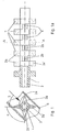
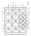
- Figur 1FIG. 1
- einen Längsschnitt durch das Gehäuse 6 eines erfindungsgemäßen Mischer/Wärmeaustauschers gemäß Linie A-A in Figur 1a und den Winkelversatz der Stege zu einander sowie die Winkelannordnung der Stege zur Hauptströmungsrichtung.a longitudinal section through the housing 6 of a mixer / heat exchanger according to the invention according to line A-A in Figure 1a and the angular offset of the webs to each other and the angular arrangement of the webs to the main flow direction.
- Figur 1aFIG. 1a
-
Teil-Querschnitt und seitliche Ansicht des Rohres 1 mit Stegen 2a und 2b nach Figur 1.Partial cross section and side view of the
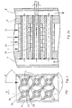
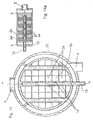
tube 1 withwebs - Figur 2FIG. 2
-
zeigt einen Mischer/Wärmeaustauscher mit zwei parallel angeordneten Rohren 1 in einer Ebene mit Stegen 2a und 2a im Bereich der Produktströmung, sowie den Winkelbereich α der Stege 2a und 2b und den Winkelbereich β der Stege zur Hauptströmungsrichtung.shows a mixer / heat exchanger with two
parallel tubes 1 in a plane withwebs webs - Figur 2aFIG. 2a
-
zeigt den Mischer/Wärmeaustauscher gemäss der Linie B-B aus Figur 2 mit einer zuftihrenden Wärmeträgerkammer 4 und einer abführenden Wärmeträgerkammer 5 und den Winkelbereich γ für die Schrägstellung der Stegrohre im Bereich der Produktströmung.shows the mixer / heat exchanger according to the line B-B of Figure 2 with a zuftihrenden
heat transfer chamber 4 and a laxativeheat transfer chamber 5 and the angular range γ for the inclination of the straw pipes in the product flow. - Figur 3, 3aFigure 3, 3a
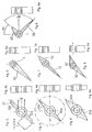
-
eine Variante zu einem Stegpaar 2a aus Figur 1 im Querschnitt.a variant of a
web pair 2a of Figure 1 in cross section. - Figur 4, 4a4, 4a
-
eine weitere Variante zu einem Stegpaar 2a aus Figur 1.a further variant of a
web pair 2a of Figure 1. - Figur 5, 5aFigure 5, 5a
-
eine weitere Variante zu einem strömungsoptimierten Stegpaar 2a aus Figur 1.a further variant of a flow-optimized
web pair 2a of Figure 1. - Figur 6, 6aFigure 6, 6a
-
eine Variante zu einem Stegpaar 2a aus Figur 1 mit nur einem Steg 62' und exzentrischem Heizkanal 3.a variant of a
web pair 2a of Figure 1 with only one web 62 'and eccentric heating channel. 3 - Figur 7, 7aFigure 7, 7a
-
eine Variante zu einem Stegpaar 2a aus Figur 1.a variant of a
web pair 2a of Figure 1. - Figur 8, 8aFigure 8, 8a
-
eine weitere Variante zu einem Stegpaar 2a aus Figur 1.a further variant of a
web pair 2a of Figure 1. - Figur 9, 9aFigure 9, 9a
-
eine weitere Variante zu einem Stegpaar 2a aus Figur 1.a further variant of a
web pair 2a of Figure 1. - Figur 10FIG. 10
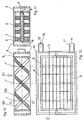
-
einen Längsschnitt gemäss Linie D-D aus Figur 12, durch eine rechteckige Mischer/Wärmeaustauscher-Einheit mit drei nebeneinander liegenden Rohren 1, 1', 1" in einer Ebene und einer um das Gehäuse verlängerten Wärmeträgerzuleitungskammer 4.a longitudinal section along line D-D of Figure 12, by a rectangular mixer / heat exchanger unit with three
adjacent tubes - Figur 11FIG. 11
- einen Querschnitt durch eine Mischer/Wärmetauschereinheit, gemäss der Linie C-C aus Figur 10 und integrierter Düse bzw. Blende 3' im Austrittsbereich des Heizkanals 3.a cross section through a mixer / heat exchanger unit, according to the line C-C of Figure 10 and integrated nozzle or aperture 3 'in the outlet region of the heating channel. 3
- Figur 12FIG. 12
-
eine Draufsicht auf eine Mischer/Wärmetauschereinheit nach Figur 10 mit Anschlüssen für die Wärmeträgerzuführung 4 und -ableitung 5.a top view of a mixer / heat exchanger unit of Figure 10 with connections for the
heat carrier supply 4 and -5 derivative. - Figur 13FIG. 13
- einen Längsschnitt durch eine Mischer/Wärmetauschereinheit mit drei in Produkt-Hauptströmungsrichtung hintereinander angeordneten Reihen von nebeneinander liegenden Rohren mit unterschiedlich dimensionierten Stegen und mit verschiedenen Rohr-Mittenabständen "a" bzw. "h" sowie definierten Spalten zur Gehäusewandung und zwischen den einzelnen Rohrebenen für die Reduzierung von Toträumen.a longitudinal section through a mixer / heat exchanger unit with three in the main product flow direction successively arranged rows of adjacent tubes with different sized bars and with different tube center distances "a" or "h" and defined columns to the housing wall and between the individual tube planes for Reduction of dead spaces.
- Figur 14FIG. 14
-
zeigt einen Querschnitt auf ein Mischer/Wärmetauscher-Einheit mit getrenntem konzentrischen Wärmezuleitungs- 4 und Wärmeableitungsbereich 5, desweiteren ist durch den Wärmezuleitungsbereich 4 eine zuführende Kapillare 13 gezeigt, als einseitige Verlängerung des Temperierkanal, um eine zusätzliche Substanz über Verteilerbohrungen 14, in den Produkthauptstrom verteilt einleiten zu können.shows a cross section of a mixer / heat exchanger unit with separate
concentric heat supply 4 andheat dissipation region 5, further by theheat supply region 4, aninfeed capillary 13 is shown as a one-sided extension of Temperierkanal to introduce an additional substance through distribution holes 14, distributed in the main product stream. - Figur 14aFigure 14a
- zeigt eine Schnittdarstellung entlang der Linie A-A aus Figur 14, insbesondere sind die Verteilerbohrungen 14 zur gleichmäßigen Verteilung einer zugeführten Substanz in den Produkthauptstrom.shows a sectional view taken along the line A-A of Figure 14, in particular, the distribution holes 14 for uniform distribution of a feed substance in the main product stream.
- Figur 15FIG. 15
-
zeigt eine modular aufgebauten Mischer/Wärmeaustauscher-Reaktor mit einer Stoff-Einleitung über Kapillare 13 und Verteilung über Bohrungen 14 für die Zuführung einer Reaktionskomponente, wobei die Anordnung vier hintereinander geschaltete Mischer/Wärmetauschereinheiten (9, 9a, 9b, 9c) mit unterschiedlichen L/D-Verhältnissen hat und die Mischer/Wärmeaustauscher-Einheiten um 90 Grad verdreht zueinander angeordnet sind.shows a modular mixer / heat exchanger reactor with a material introduction via
capillary 13 and distribution throughholes 14 for the supply of a reaction component, the arrangement having four successive mixer / heat exchanger units (9, 9a, 9b, 9c) with different L / D ratios and the mixer / heat exchanger units are rotated by 90 degrees to each other.
Figur 1 zeigt ein einstückiges Rohr 1 in einem produktdurchströmten Gehäuse 6, welches auf dem äußeren Umfang einen Stegbereich hat und zwei unter einem Winkel β = 45 bzw. -135° zur Hauptströmungsrichtung (Pfeil) stehende radiale Mischstege 2a, 2a' in einen vorderen, im Schnitt dargestellten und einem hinteren Stegbereich mit zwei weiteren Stegen 2b, 2b' besitzt. Die Breite des Stegbereichs ist hier so gewählt, dass alternierend zwei Steglagen mit jeweils zwei Stegen 2a, 2a' und 2b, 2b' entlang der Rohrachse radial versetzt zueinander im Gehäuse 6 angeordnet sind, und sie sich in ihrer axialen Ausdehnung lückenlos anschließen (siehe Figur 1a).1 shows a one-
Die Form bzw. Ausgestaltung der Stege und die StegoberflächenbeschaFfenheit kann unterschiedlich sein. Die Oberfläche der Stege und des Rohres kann z.B. strukturiert sein durch erhobene Noppen, Warzen bzw. Rillen oder Nuten, um die wärmeübertragende Fläche zu vergrößern und zusätzliche Strömungseffekte zu produzieren. Im Wesentlichen richtet sie sich nach der verfahrenstechnischen Aufgabe oder Anforderung. In den Figuren 3 bis 9 sind Beispiele hierzu wiedergegeben. Die Stege können am äußeren Umfang des Rohres 1 radial symmetrisch (wie in Fig. 3-5) oder auch asymmetrisch (Fig. 7-9) angeordnet sein und zueinander unterschiedliche Winkel zeigen, wobei auch unterschiedliche Stegformen miteinander kombiniert werden können und Fig. 7-9 miteinander korrespondieren. Die Stegform kann von der radialen einfachen Form abweichen dahingehend, dass sie zusätzlich eine gekrümmte Form als Leitschaufel zeigen, das ist besonders vorteilhaft wenn sich die konzentrischen Bereiche überschneiden und Sekundärströmungen erzwungen werden.The shape or configuration of the webs and the web surface condition may be different. For example, the surface of the lands and the pipe may be structured by raised knobs, warts or grooves to increase the heat transferring area and to produce additional flow effects. Essentially, it depends on the process task or requirement. Examples are given in FIGS. 3 to 9. The webs may be arranged radially symmetrically (as in FIGS. 3-5) or also asymmetrically (FIGS. 7-9) on the outer circumference of the
Figur 3, 3a zeigen einen Querschnitt bzw. Längsschnitt durch ein Rohr 1 ähnlich Fig. 1 mit zwei Stegen 32a, 32a' die einen konstanten Durchmesser aufweisen und eine Abflachung 31 quer zur Hauptströmungsrichtung 21 an ihren Enden haben.Figure 3, 3a show a cross-section or longitudinal section through a
In der Variante nach Fig. 4, 4a sind die Stege 42a, 42a' im Querschnitt am Ende verjüngt ausgebildet. Die Stege 52a, 52a' nach Variante gemäß Fig. 5, 5a sind ähnlich der Fig. 4, jedoch mit verbreiterten Fuß entsprechend dem Durchmesser des Rohres 1 ausgeführt.In the variant according to FIGS. 4, 4 a, the
Fig. 6 zeigt eine Variante eines Stegrohres 1 ähnlich der nach Fig. 5, jedoch mit nur einem Steg 62' in einer Steglage. Die Bauform nach Fig. 7 kombiniert Stegformen nach Fig. 4 und Fig. 5 hier mit unterschiedlicher radialer Ausdehnung der Stege 72, 72'. In der Ausführung nach Fig. 8, die Fig. 7 ähnlich ist, sind beide Stege 82, 82' im Querschnitt und einem Winkel von 170°C um die Rohrachse verdreht zueinander angeordnet.Fig. 6 shows a variant of a
In der Variante nach Fig. 9 beträgt der Winkelversatz 90°C, zwischen den Stegen 92 und 92' verglichen mit der Anordnung nach Fig. 7.In the variant according to FIG. 9, the angular offset is 90 ° C., between the
Durch die Form und Anordnung der Stege kann die wärmeübertragende Fläche auf der produktberührten Seite und auch das Umströmen des Rohres und damit auch der wichtige Mischvorgang begünstigt werden. Insbesondere bei Temperiervorgängen von hochviskosen Medien, mit einer Viskosität von größer 1 Pa.s, ist eine definierte Anordnung der Stege auf dem äußeren Umfang des Rohres sinnvoll, um neben der Wärmeübertragung auch eine effektive Mischwirkung zu erzielen. Zur Erhöhung der Heizleistung kann die innere Kontur der Stegrohre 1, die in Kontakt mit dem Temperiermittel steht, ebenfalls mit Rippen ausgestattet werden. Dadurch wird die Heizfläche auf der Wärme- oder Kälteträgerseite wesentlich erhöht.Due to the shape and arrangement of the webs, the heat-transferring surface on the product-contacted side and also the flow around the pipe and thus the important mixing process can be favored. In particular, in tempering of highly viscous media, with a viscosity of greater than 1 Pa.s, a defined arrangement of the webs on the outer circumference of the tube is useful to achieve in addition to the heat transfer and an effective mixing effect. To increase the heating power, the inner contour of the
Die Rohrform mit beliebig vielen bzw. gezielt angeordneten Stegbereichen auf dem äußeren Rohrdurchmesser kann wirtschaftlich im Gießverfahren oder in einem Schmiedeverfahren hergestellt werden, dadurch wird immer sichergestellt, dass ein vollständiger metallischer Kontakt zwischen Rohr und erhabene äußere Kontur besteht. In besonderen Fällen können die radialen Stege hohl ausgeführt sein, so dass der Steghohlraum eine direkte Verbindung zum Temperierraum hat und überall konstante Wanddicken vorliegen. Anforderungen bezüglich mechanischer Festigkeiten und benötigter Druckfestigkeit erfolgt durch entsprechende Wahl der Wanddicke.The tubular shape with any number or selectively arranged web areas on the outer pipe diameter can be produced economically by casting or in a forging process, thereby always ensures that there is a complete metallic contact between the pipe and raised outer contour. In special cases, the radial webs may be hollow, so that the web cavity has a direct connection to the temperature control and everywhere constant wall thicknesses are present. Requirements regarding mechanical strength and required compressive strength are made by appropriate choice of wall thickness.
Die Rohre können aus unterschiedlichen Werkstoffen hergestellt werden, damit eine ausreichend hohe Korrosionsbeständigkeit gewährleistet ist.The pipes can be made of different materials to ensure a sufficiently high corrosion resistance.
Das Gießverfahren lässt eine wirtschaftliche Fertigung von nur einer bestimmten Rohrlänge zu. Größere Rohrlängen müssen durch Verbinden mehrerer Rohreinheiten mit einem geeigneten Schweißverfahren hergestellt werden.The casting process allows economical production of only a specific pipe length. Larger pipe lengths must be made by connecting several pipe units with a suitable welding process.
Ein weiterer Mischer/Wärmeaustauscher ist in Figur 2 im Längsschnitt wiedergegeben. Sechs Rohre 1 haben zwei parallele Lagen von Stegen 2a und 2b mit jeweils auf dem äußeren Umfang der Rohre zwei radial versetzten Stegen 2a, 2a'. Die Rohre 1 ragen mit einem Ende in eine Wärmeträger-Zuführkammer 4 und enden in einer Wärmeträger-Ableitkammer 5 (Figur 2a). Die Rohre 1 sind mit der Zuführ- 4 und der Ableitkammer 5 verschweißt. Die Rohre 1 stehen in einem Winkel γ von ca. 5 Grad quer zur Hauptströmungsrichtung 21 des Produktes. Die Rohre 1 mit den Stegen sind so positioniert, dass die Stege in einen Winkel β von 45 Grad zur Produktanströmung 21 positioniert sind. Die Stege 2a stehen zu den versetzten Stegen 2b in einem Winkel α von 90 Grad.Another mixer / heat exchanger is shown in Figure 2 in longitudinal section. Six
Die Zufiihrkammer 4 und Ableitkammer 5 des Temperiermittels bestehen aus einer am Gehäuse 6 angeschweißten Tasche bzw. einem Halbrohr (nicht gezeichnet).The
In Figur 10 ist eine Mischer/Wärmeaustauschereinheit gezeigt, mit einem rechteckigen Gehäuse 6 und drei Stegrohren 1, 1', 1". Die Stege 12a, 12b entsprechen in ihrer Bauform den in Fig. 3 gezeigten Typen und sind über die Länge der Rohre 1, 1', 1" in alternierenden Lage angeordnet.10 shows a mixer / heat exchanger unit, with a rectangular housing 6 and three
Im Querschnitt in Fig. 11 gemäß Linie C-C aus Fig. 10 ist zu sehen, dass durch eine äußere Ummantelung 15 zwei Kammern 4, 5 gebildet werden, die mit einer Zuleitung 16 bzw. einer Ableitung 17 für einen flüssigen Wärmeträger verbunden sind (siehe Fig. 12). Die Rohre 1, 1', 1" werden wie in Fig. 11 gezeigt im Betrieb vom Wärmeträger 18 durchströmt. An ihrem einen Ende weisen die Rohre 1, 1', 1" eine Verengung 3' im Kanal 3 auf.In the cross section in FIG. 11 along the line CC from FIG. 10, it can be seen that two
Der Mischer/Wärmeaustauscher (vergleiche Schnittbild in Fig. 12) hat einen durch das Gehäuse 6 gebildeten rechteckigen Produktströmungsbereich. Das weitere das Gehäuse 6 umgebende Gehäuse 15, das mit Trennstegen unterteilt ist, bildet die Kammern 4, 5 für den Wärmeträger 18. Mehrere gemäß Fig. 10 geformte Mischer/Wärmeaustauschereinheiten sind in Strömungsrichtung hintereinander angeordnet und an eine Produktleitung bündig angeschlossen. Das Produkt durchströmt die Einheiten entsprechend Fig. 10 von oben (Strömungsrichtung 21).The mixer / heat exchanger (see cross-sectional view in FIG. 12) has a rectangular product flow area formed by the housing 6. The further housing 6 surrounding the
Eine weitere Möglichkeit der Zu- und Ableitung der Temperierflüssigkeit besteht darin, dass um das Wärmeaustauschergehäuse mit innenliegenden Stegrohren ein Ring bzw. Mantelrohr, welches wiederum zwei Trennstege besitzt um eine Trennung zwischen Vor- und Rücklauf des Wärmeträgers zu gewährleisten (vergleiche Figur 14), gestülpt und verschweißt wird. Bei einer runden Wärmeträgerkammer und Gehäuse sind die temperierbaren Rohre 1 mit ihren Stegen in der Anströmebene des Produkts unterschiedlich lang.Another way of supplying and discharging the heat transfer liquid is that around the heat exchanger housing with inner struts a ring or jacket tube, which in turn has two dividers to ensure a separation between flow and return of the heat carrier (see Figure 14), slipped and welded. In a round heat transfer chamber and Housing are the temperature-
Die Stegform und -richtung kann im Zusammenspiel mit den horizontalen Rohrabständen "a" oder den vertikalen Rohrabständen "h" untereinander eine optimale temperierbare Mischer/Wärmeaustauschergeometrie bilden, mit großer Wärmeübertragungsfläche und hoher Mischwirkung. Die Rohre mit den äußeren Stegen können unterschiedliche Rohrabstände zeigen, sie können so eng gewählt werden, dass die konzentrischen Stegbereiche sich überlappen und die äußeren Mischstege sich miteinander kreuzen (vergl. Figur 13). Dadurch kann die wärmeübertragende Fläche pro Volumeneinheit variiert und die Verweilzeit des Produkts verkleinert werden. Die Rohre in einer Ebene können unterschiedliche Stegformen und -anordnungen zeigen.The web shape and direction, in conjunction with the horizontal pipe distances "a" or the vertical pipe distances "h" with each other form an optimal temperature-mixable mixer / heat exchanger geometry, with large heat transfer surface and high mixing effect. The tubes with the outer webs can show different pipe spacings, they can be chosen so narrow that the concentric web areas overlap and the outer mixing webs intersect with each other (see Figure 13). Thereby, the heat transferring area per unit volume can be varied and the residence time of the product can be reduced. The tubes in a plane can show different web shapes and arrangements.
Fig. 13 zeigt eine Mischer Wärmeaustauscheranordnung ähnlich der in Fig. 10 gezeigten Form jedoch mit zwei weiteren Reihen von Stegrohren 131, 132, die in Produktströmungsrichtung 21 hintereinander angeordnet sind.FIG. 13 shows a mixer heat exchanger arrangement similar to that shown in FIG. 10, but with two further rows of
Die erste Reihe von Stegrohren 1, 1', 1" mit Stegen 12 a, 12b entspricht der in Fig. 10 gezeigten Form.The first series of
In den weiteren Reihen sind die Rohre 131, 132 mit den äußeren Stegen so angeordnet, dass die jeweils endständigen Stege zum Gehäuse 6 einen definierten Spalt zeigen, um ein möglichst vollständiges Umfließen der Stegrohre insbesondere zur Gehäusewand 6 zu ermöglichen (Figur13, Ebene 2u. 3). Dieser Spalt verhindert die Bildung von Toträumen in Strömungsrichtung, in denen sich Produkte ablagern können welches zur Qualitätsminderung der Produkte aufgrund langer Temperaturbelastung führt. Gleichzeitig erfolgt eine zusätzliche Temperierung durch die gezielte Führung des Produktes zum temperierten Gehäuse.In the further rows, the
Die temperierbaren Mischer/Wärmeaustauscher können gemäß der Variante nach Fig. 14 dazu benutzt werden, um eine einzumischende Komponente gleichmäßig im Produkt zu verteilen. Bei dieser Anwendung werden in dem mittleren Rohr 13 im Bereich der Stege 2a, 2b kleine Eintrittsöffnungen 14 eingebracht, die es ermöglichen eine einzumischende Komponente über eine Rohrverlängerung (13) durch den Heizmittelraum zu zuführen und über die eingebrachten Öffnungen 14 über den gesamten Produktströmungsquerschnitt gleichmäßig einzutragen (Figur 14, 14a).According to the variant according to FIG. 14, the temperature-controllable mixers / heat exchangers can be used to distribute a component to be admixed uniformly in the product. In this application,
Eine Kombination mehrerer Mischer/Wärmeaustauscher 9, 9a, 9b, 9c zu einem Strömungsreaktor ist in Figur 15 skizzenhaft im Schnitt gezeigt. Die Einheit 9a hat hier ein L/D-Verhältnis von 1,5 während die übrigen Einheiten des Reaktors ein L/D-Verhältnis von 0,75 haben. Die Einheiten sind zueinander um 90 Grad versetzt angeordnet. Die zuleitenden Wärmeträgerkammern 4 und ableitenden Wärmeträgerkammem 5 der Mischer/Wärmeaustauscher-Einheiten sind alle parallel mit der Wärmeträgerversorgung verbunden. Die Temperierrohre 1 mit Stegen sind in den Einheiten 9, 9b durch unterbrochene Linien und in den Einheiten 9a, 9c durch die Kreuzungspunkte der unterbrochenen Linien angedeutet. Es ist zu erkennen, dass die Einheiten in der horizontalen und in der vertikalen Ebene bzw. in Hauptstromrichtung 21 unterschiedlich viele Stegrohre zur Temperierung besitzen, um im jeweiligen Modul eine differenzierte Temperier- und Dispergierleistung zu bewirken. In der Einheit 9 ist das mittlere Rohr nur einseitig geöffnet (ähnlich der Ausführung in Figur 14a) und durch eine Kapillare 13 einseitig durch die Temperierkammer 4 verlängert bis außerhalb der Mischer/Wärmeaustauscher-Einheit 9. Außerhalb der Einheit 9 kann nun eine Dosierpumpe, die in der Figur 15 nicht dargestellt ist, angeschlossen werden, um z.B. eine weitere Substanz (Additiv, Schleppmittel, Reaktionsstoffe) über den gesamten Strömungsquerschnitt des Modul bzw. der Einheit zu dosieren und zu verteilen. Bohrungen bzw. Düsen 14 entlang des Rohres im Produktstrom sorgen für eine gleichmäßige Verteilung über den Strömungsquerschnitt der Einheit.A combination of several mixers /
Je nach Volumenstrom des Wärmeträgermediums (z.B. Warmwasser, Öl, Kühlsole) ist es erforderlich im Austrittsbereich der Stegrohre eine Querschnittsverengung bzw. eine Düse (Blende) vor zu sehen, damit parallel angeströmte Stegrohre mit gleicher Energiedichte versorgt werden. In einfachster Ausführung wird der Innendurchmesser 3 des Rohres im Austrittsbereich zur ableitenden Wärmeträgerkammer auf kurzer Strecke verkleinert, z.B. auf den Innendurchmesser 3', ähnlich wie in Figur 11 dargestellt ist. Wird Dampf als Energieträger eingesetzt ist diese Verengung des Innendurchmessers 3 des Rohres 1 nicht erforderlich.Depending on the volume flow of the heat transfer medium (for example hot water, oil, cooling brine), it is necessary to provide a cross-sectional constriction or a nozzle in the outlet area of the tubes to supply the same energy density to parallel-flowed tubes. In the simplest embodiment, the
Kompaktwärmeaustauscher haben die Aufgabe in kurzer Zeit ein durchströmendes Medium möglichst hoch, d.h. möglichst nahe an die Heizmitteltemperatur zu erhitzen, so dass aufgrund einer kurzzeitigen Temperaturbelastung keine thermische Schädigung des Produkts auftritt. Kompaktwärmeaustauscher sollen kleinere Apparateabmessungen haben, als bekannte Wärmeaustauscher mit gleicher Leistung, damit in einer verfahrenstechnischen Anlage nur ein kleiner Raumbedarf und dadurch geringe Montage- und Investitionskosten entstehen. Ein wesentliches Merkmal zum Vergleich verschiedener Wärmeaustauschertypen ist die Wärmeübertragungsleistung, die benötigte Wärmeaustauschfläche und das produktseitige Apparatevolumen. Es wurde der erfindungsgemäße Mischer/Wärmeaustauscher mit einem Gerät aus dem Stand der Technik (Offenlegungsschrift DE-2 839 564 A1) verglichen. Der untersuchte erfindungsgemäße Mischer/Wärmeaustauscher entsprach grundsätzlich der in Figur 2 und 2a gezeigten Ausführung jedoch mit vier statt zwei quer zur Produktströmungsrichtung nebeneinander angeordneten Rohren und insgesamt neun statt drei in Strömungsrichtung 21 gesehen hintereinander angeordneten Rohrpaketen (vergleiche Figur 2a).Compact heat exchangers have the task in a short time a medium flowing through as high as possible, ie to heat as close to the heating medium temperature, so that due to a short-term temperature load no thermal damage to the product occurs. Compact heat exchangers should have smaller apparatus dimensions, as known heat exchangers with the same performance, so that in a process engineering system only a small space requirement and thus low installation and investment costs arise. An essential feature for comparing different types of heat exchangers is the heat transfer performance, the required heat exchange area and the product-side apparatus volume. The mixer / heat exchanger according to the invention was compared with a device from the prior art (Offenlegungsschrift DE-2 839 564 A1). The investigated mixer / heat exchanger according to the invention basically corresponded to the embodiment shown in FIGS. 2 and 2a with four rather than two tubes arranged side by side transversely of the product flow direction and overall nine instead of three seen in the
Für den Versuch wurde als Produkt ein hochviskoser Stoff (Silikonöl) mit einer Viskosität von 10 Pa.s gewählt und mit einer Zahnradpumpe durch die Wärmeaustauscher gepumpt, so dass im Austrittsbereich des jeweiligen Apparates der Massenstrom gravimetrisch ermittelt werden konnte. Die Wärmeaustauscher wurden für den Versuch an einen elektrisch beheizten und geregelten Thermostaten (Heizleistung 3 kW) angeschlossen. Als Wärmeträgermedium wurde Wasser gewählt, so dass der Thermostatregler für die Vorlauftemperatur am Thermostaten auf 90°C eingestellt wurde. Die Eintritts- und Austrittstemperatur des Wärmeträgers und der Produktseite wurden mittels eines Thermoelements vom Typ Pt-100 gemessen und auf einer Messwerterfassungsanlage registriert und gespeichert. Zusätzlich registrierten Drucksensoren, die im Eintritts- und Austrittsbereich der Temperier- und Produktseite auftretenden Drücke, als Folge der auftretenden Strömungsverluste. Die apparativen Kenndaten der Wärmeaustauscher sind in der Tabelle 1 zusammengefasst.
Die Apparatedaten zeigen konstruktiv bedingte Abweichungen. Aus der Tabelle 1 ist zu entnehmen, dass der Mischer/Wärmeaustauscher eine kürzere Bauform und dadurch ein geringeres produktseitiges Volumen (Hold-up) hat. Zusätzlich hat der Mischer/Wärmeaustauscher eine um 0,01 qm geringere wirksame Wärmeübertragungsfläche. Bauartbedingt ist beim Mischer/Wärmeaustauscher immer ein Teilbereich des Gehäuses temperiert. Für die Versuchsauswertung ist die wirksame Gesamttemperierfläche eingesetzt worden. Aus den durchgeführten Versuchen, den gemessenen Temperaturen und Drücken, wurden die charakteristischen Kenndaten errechnet und in der Tabelle 2 für beide Wärmeaustauscher gegenüber gestellt. Es wurde die übertragene Wärmeleistung, der mittlere Wärmedurchgangskoeffizient und der Druckverlust aus den aufgezeichneten Messwerten berechnet worden.The apparatus data show constructive deviations. From Table 1 it can be seen that the mixer / heat exchanger has a shorter design and thus a lower product-side volume (hold-up). In addition, the mixer / heat exchanger has an effective heat transfer area of less than 0.01 square meters. Due to the design, a partial area of the housing is always tempered in the mixer / heat exchanger. For the evaluation of the test, the effective overall tempering surface has been used. From the experiments carried out, the measured temperatures and pressures, the characteristic characteristics were calculated and compared in Table 2 for both heat exchangers. The transferred heat output, the average heat transfer coefficient and the pressure loss were calculated from the recorded measured values.
In der Tabelle 2 sind die errechneten Leistungsdaten der Wärmeaustauscher für einen konstanten Volumenstrom (Silikonöl) von ca. 30 l/h dargestellt.
Das Ergebnis der Versuche bestätigt die höhere Leistungsfähigkeit des erfindungsgemäßen kompakten Mischer/Wärmeaustauschers. Es wurde bei konstantem Volumenstrom und geringerer Verweilzeit in der beheizten Zone ca. 120 Watt mehr übertragen, obwohl die produktberührte Wärmeübertragungsfläche geringer ist als bei dem bekannten Wärmeaustauscher. Aufgrund der kompakten Bauform des Mischer/Wärmeaustauschers konnte die Verweilzeit halbiert werden.The result of the tests confirms the higher performance of the compact mixer / heat exchanger according to the invention. With a constant volume flow and reduced residence time in the heated zone, about 120 watts more was transferred, although the product-contacting heat transfer area is lower than at the known heat exchanger. Due to the compact design of the mixer / heat exchanger, the residence time was halved.
Das Testergebnis bestätigt eine wesentliche Verbesserung der Wärmeübertragungsleistung bei geringerer Verweilzeit durch den erfindungsgemäßen Mischer/Wärmeaustauscher. The test result confirms a substantial improvement in the heat transfer performance with less residence time by the mixer / heat exchanger according to the invention.
Claims (18)
- Static mixer/heat exchanger for the treatment of viscous and highly viscous products, at least comprising one housing (6) for passing the product, at least two temperature-controllable tubes (1) which are provided, in particular, with a passage (3) for passing a heat-carrying medium, the housing surrounding the tubes (1) and a multiplicity of heat-exchanger fins (2a, 2b) being mounted distributed on the circumference of the tubes (1), characterised in that the heat exchanger fins (2a, 2b) are aligned along the tubes (1) in at least two parallel layers (7, 8) and the fins (2a) and (2b) of adjacent layers (7, 8) are in each case rotationally offset to one another by an angle α of from 45° to 135°, preferably from 70° to 110°, about the axis of the tube (1) carrying the fins, and in that the fins (2a, 2b) are disposed at an angle P of from ±10° to ±80° to the main flow direction (21) of the product through the housing (6) and the temperature-controllable tubes are mounted with fins side-by-side in the housing transversely to the main flow direction of the product.
- Mixer/heat exchanger according to claim 1, characterised in that with respect to each fin (2a) or (2b) of a layer (7) or (8) a fin (2a') or (2b') opposed to this fin (2a) or (2b) is arranged on the tube (1).
- Mixer/heat exchanger according to claim 1 or 2, characterised in that the fins (2a) or (2b) of the different layers (7) or (8) are arranged alternatingly, viewed along the length of the tube (1).
- Mixer/heat exchanger according to any one of claims 1 to 3, characterised in that the angle α between the fins of the different layers (7, 8) is from 85° to 95°.
- Mixer/heat exchanger according to any one of claims 1 to 4, characterised in that the housing (6) includes supply lines (4) and discharge lines (5) for a heat-carrying medium which are connected respectively to the inlets and outlets of the passages (3, 3').
- Mixer/heat exchanger according to any one of claims 1 to 5, characterised in that tubes (1, 1') provided with fins (2a, 2b) are mounted in the housing (6) in a plurality of planes one behind the other.
- Mixer/heat exchanger according to any one of claims 1 to 6, characterised in that the radial extension of the respective neighbouring fins (2a, 2b) arranged on neighbouring tubes (132, 132') overlaps.
- Mixer/heat exchanger according to any one of claims 1 to 7, characterised in that the fins (2a, 2b) of the different layers (7, 8) are staggered with respect to one another along the tubes (1, 1', 1").
- Mixer/heat exchanger according to any one of claims 1 to 8, characterised in that the radial extension of the fins (2a, 2b) is at least 0.5 times the internal diameter of the tube (1) connected thereto.
- Mixer/heat exchanger according to any one of claims 1 to 9, characterised in that the internal walls of the tubes (1, 1', 1") include contouring, in particular in the form of longitudinal ribs, to increase their surface area.
- Mixer/heat exchanger according to any one of claims 1 to 10, characterised in that selected fins (2, 2a', 2b, 2b') of the tubes (1) are internally hollow and the cavity is connected to the passage (3) of the tube (1).
- Mixer/heat exchanger according to any one of claims 1 to 11, characterised in that the tubes (1, 1', 1") are provided with a resistance heater or an electric cooling element.
- Mixer/heat exchanger according to any one of claims 1 to 12, characterised in that the tubes (1, 1', 1") and/or the fins (2a, 2b) are coated with a catalyst.
- Mixer/heat exchanger according to any one of claims 1 to 13, characterised in that the tubes (1, 1', 1") are arranged in a transverse direction at an angle γ of not more than +/-15° to the main flow direction of the product in the housing (6).
- Mixer/heat exchanger according to any one of claims 1 to 14, characterised in that tubes (1, 1a) provided with fins (2a, 2b) are mounted in a plurality of planes one behind the other in the housing (6), and the tubes (1) of the planes have differently dimensioned fins (2a, 2b) in comparison to the fins of the tubes (1a) of the neighbouring plane.
- Mixer/heat exchanger according to any one of claims 1 to 15, characterised in that the mixer/heat exchanger includes at least one medium induction tube which is arranged parallel to the tubes (1), is provided with fins (2a, 2b) of the same kind and has a plurality of openings (14) into the interior of the housing (6).
- Mixer/heat exchanger according to any one of claims 1 to 16, characterised in that the tubes (1) include passages (3) in the outlet region of which a jet (3') of reduced diameter as compared to the passages (3) is mounted.
- Use of the mixer/heat exchanger according to any one of claims 1 to 17 for the temperature control of viscous medium systems having a viscosity of 0.001 to 20 000 Pa.s.
Applications Claiming Priority (2)
| Application Number | Priority Date | Filing Date | Title |
|---|---|---|---|
| DE10233506A DE10233506B4 (en) | 2002-07-24 | 2002-07-24 | Mixer / heat exchanger |
| DE10233506 | 2002-07-24 |
Publications (2)
| Publication Number | Publication Date |
|---|---|
| EP1384502A1 EP1384502A1 (en) | 2004-01-28 |
| EP1384502B1 true EP1384502B1 (en) | 2006-01-11 |
Family
ID=29796539
Family Applications (1)
| Application Number | Title | Priority Date | Filing Date |
|---|---|---|---|
| EP03015959A Expired - Lifetime EP1384502B1 (en) | 2002-07-24 | 2003-07-14 | Mixer, heat exchanger |
Country Status (6)
| Country | Link |
|---|---|
| US (1) | US7220048B2 (en) |
| EP (1) | EP1384502B1 (en) |
| JP (1) | JP4430347B2 (en) |
| AT (1) | ATE315434T1 (en) |
| DE (2) | DE10233506B4 (en) |
| ES (1) | ES2256622T3 (en) |
Cited By (1)
| Publication number | Priority date | Publication date | Assignee | Title |
|---|---|---|---|---|
| DE102011085944A1 (en) | 2010-11-10 | 2012-05-10 | Bayer Materialscience Aktiengesellschaft | Process for the continuous production of thermoplastically processable polyurethanes |
Families Citing this family (44)
| Publication number | Priority date | Publication date | Assignee | Title |
|---|---|---|---|---|
| US7622094B2 (en) * | 2004-11-19 | 2009-11-24 | Larry Lewis | Method of recovering energy using a catalytic finned heat exchanger |
| US7587901B2 (en) | 2004-12-20 | 2009-09-15 | Amerigon Incorporated | Control system for thermal module in vehicle |
| JP4989062B2 (en) * | 2005-04-28 | 2012-08-01 | バブコック日立株式会社 | Fluid mixing device |
| US20090038701A1 (en) | 2006-01-17 | 2009-02-12 | Baxter International Inc. | Device, system and method for mixing |
| US20080087316A1 (en) | 2006-10-12 | 2008-04-17 | Masa Inaba | Thermoelectric device with internal sensor |
| JP5080779B2 (en) * | 2006-10-25 | 2012-11-21 | テルモ株式会社 | Method for producing liposome preparation |
| WO2008115831A1 (en) | 2007-03-16 | 2008-09-25 | Amerigon Incorporated | Air warmer |
| DE502008002619D1 (en) * | 2007-05-24 | 2011-03-31 | Atlas Holding Ag | FLOW CHANNEL FOR A MIXER HEAT EXCHANGER |
| DE102007038332A1 (en) * | 2007-08-14 | 2009-02-19 | Wacker Chemie Ag | Continuous polymerization process |
| DE102007040850A1 (en) | 2007-08-29 | 2009-03-05 | Wacker Chemie Ag | Process for the preparation of protective colloid-stabilized polymers and apparatus for carrying out the process |
| WO2009036077A1 (en) | 2007-09-10 | 2009-03-19 | Amerigon, Inc. | Operational control schemes for ventilated seat or bed assemblies |
| US7887764B2 (en) * | 2007-09-18 | 2011-02-15 | Jernberg Gary R | Mixer with a catalytic surface |
| ATE518634T1 (en) * | 2007-09-27 | 2011-08-15 | Sulzer Chemtech Ag | DEVICE FOR PRODUCING A REACTIVE FLOWING MIXTURE AND USE THEREOF |
| US8181290B2 (en) | 2008-07-18 | 2012-05-22 | Amerigon Incorporated | Climate controlled bed assembly |
| KR20100111726A (en) | 2008-02-01 | 2010-10-15 | 아메리곤 인코포레이티드 | Condensation and humidity sensors for thermoelectric devices |
| FR2929856B1 (en) * | 2008-04-15 | 2010-08-20 | Rhodia Operations | PROCESS FOR THE PREPARATION OF CRYSTALS BASED ON A FATTY ACID ESTER |
| WO2010088405A1 (en) * | 2009-01-28 | 2010-08-05 | Amerigon Incorporated | Convective heater |
| CN101762189B (en) * | 2010-03-11 | 2011-06-22 | 刘小江 | Countercurrent tube bundle type wall-type heat exchanger |
| US9121414B2 (en) | 2010-11-05 | 2015-09-01 | Gentherm Incorporated | Low-profile blowers and methods |
| US20120127820A1 (en) * | 2010-11-23 | 2012-05-24 | Noles Jr Jerry W | Polymer Blending System |
| US8905627B2 (en) | 2010-11-23 | 2014-12-09 | Jerry W. Noles, Jr. | Polymer blending system |
| EP2565572A1 (en) * | 2011-09-02 | 2013-03-06 | Aurotec GmbH | Heat exchange conduit system |
| US9685599B2 (en) | 2011-10-07 | 2017-06-20 | Gentherm Incorporated | Method and system for controlling an operation of a thermoelectric device |
| JP5901361B2 (en) * | 2011-11-18 | 2016-04-06 | 住友化学株式会社 | Continuous polymerization apparatus and method for producing polymer composition |
| US9989267B2 (en) | 2012-02-10 | 2018-06-05 | Gentherm Incorporated | Moisture abatement in heating operation of climate controlled systems |
| DE102012005513A1 (en) * | 2012-03-19 | 2013-09-19 | Bundy Refrigeration Gmbh | Heat exchanger, process for its preparation and various systems with such a heat exchanger |
| JP5984702B2 (en) * | 2013-01-31 | 2016-09-06 | 住友化学株式会社 | Continuous polymerization apparatus and method for producing polymer composition |
| US20150087733A1 (en) | 2013-09-20 | 2015-03-26 | Rolf Heusser | Method for the Manufacture of Foams of Low Density |
| US9777973B2 (en) | 2013-09-20 | 2017-10-03 | Promix Solutions Ag | Device for mixing and heat exchange |
| US9662962B2 (en) | 2013-11-05 | 2017-05-30 | Gentherm Incorporated | Vehicle headliner assembly for zonal comfort |
| CN106028874B (en) | 2014-02-14 | 2020-01-31 | 金瑟姆股份公司 | Conductive convection climate control seat |
| EP3141824B1 (en) * | 2014-05-09 | 2020-09-16 | Eco Factory Co. Ltd. | Air conditioning system |
| US11639816B2 (en) | 2014-11-14 | 2023-05-02 | Gentherm Incorporated | Heating and cooling technologies including temperature regulating pad wrap and technologies with liquid system |
| US11033058B2 (en) | 2014-11-14 | 2021-06-15 | Gentherm Incorporated | Heating and cooling technologies |
| US11857004B2 (en) | 2014-11-14 | 2024-01-02 | Gentherm Incorporated | Heating and cooling technologies |
| US9572555B1 (en) * | 2015-09-24 | 2017-02-21 | Ethicon, Inc. | Spray or drip tips having multiple outlet channels |
| EP3489603B1 (en) | 2017-11-28 | 2021-06-16 | Promix Solutions AG | Heat exchanger |
| JP6961224B2 (en) * | 2017-12-28 | 2021-11-05 | ホクシン産業株式会社 | Fuel oil transfer device |
| US20200035898A1 (en) | 2018-07-30 | 2020-01-30 | Gentherm Incorporated | Thermoelectric device having circuitry that facilitates manufacture |
| US11152557B2 (en) | 2019-02-20 | 2021-10-19 | Gentherm Incorporated | Thermoelectric module with integrated printed circuit board |
| DE102019009099A1 (en) * | 2019-12-31 | 2021-07-01 | Heinz Gross | Heat exchanger with mixing function |
| CN112179176B (en) * | 2020-09-24 | 2022-01-14 | 金湖正泓企业策划有限公司 | Flow-dividing type heat exchanger for heat exchange based on high-density pipeline |
| CN113916037A (en) * | 2021-10-13 | 2022-01-11 | 江苏科技大学 | Snowflake-shaped fin phase-change heat storage device |
| WO2024052189A1 (en) * | 2022-09-06 | 2024-03-14 | Basf Se | Discontinuously operated desublimator having at least one flow disruptor |
Family Cites Families (15)
| Publication number | Priority date | Publication date | Assignee | Title |
|---|---|---|---|---|
| BE465451A (en) * | ||||
| US1921927A (en) * | 1929-08-01 | 1933-08-08 | Griscom Russell Co | Fin tubing |
| GB521548A (en) * | 1938-10-18 | 1940-05-24 | Edward Frank Spanner | Improvements in tubular heat exchange apparatus |
| US2322341A (en) * | 1940-01-27 | 1943-06-22 | Morris F Booth | Heat exchange unit |
| GB569000A (en) * | 1946-01-18 | 1945-04-30 | Edward Frank Spanner | Improvements in tubes for heat exchange apparatus |
| DE836946C (en) * | 1947-09-19 | 1952-04-17 | Andre Huet | Countercurrent heat exchanger |
| US3111168A (en) * | 1954-11-24 | 1963-11-19 | Huet Andre | Heat exchangers |
| JPS5716319B2 (en) * | 1973-09-03 | 1982-04-03 | ||
| DE2839564C2 (en) * | 1978-09-12 | 1982-10-21 | Hoechst Ag, 6000 Frankfurt | Device with supply and removal of heat and for mixing liquid media |
| US4877087A (en) * | 1984-08-16 | 1989-10-31 | Sundstrand Heat Transfer, Inc. | Segmented fin heat exchanger core |
| US4865460A (en) * | 1988-05-02 | 1989-09-12 | Kama Corporation | Static mixing device |
| EP0526393B1 (en) * | 1991-07-30 | 1996-08-28 | Sulzer Chemtech AG | mixing-in device |
| US5472047A (en) * | 1993-09-20 | 1995-12-05 | Brown Fintube | Mixed finned tube and bare tube heat exchanger tube bundle |
| DE19837671A1 (en) * | 1998-08-20 | 2000-02-24 | Bayer Ag | Static mixer |
| DE50003420D1 (en) * | 1999-07-07 | 2003-10-02 | Fluitec Georg Ag Winterthur | Heat exchange device |
-
2002
- 2002-07-24 DE DE10233506A patent/DE10233506B4/en not_active Withdrawn - After Issue
-
2003
- 2003-07-14 AT AT03015959T patent/ATE315434T1/en not_active IP Right Cessation
- 2003-07-14 ES ES03015959T patent/ES2256622T3/en not_active Expired - Lifetime
- 2003-07-14 DE DE50302165T patent/DE50302165D1/en not_active Expired - Lifetime
- 2003-07-14 EP EP03015959A patent/EP1384502B1/en not_active Expired - Lifetime
- 2003-07-18 US US10/622,625 patent/US7220048B2/en not_active Expired - Fee Related
- 2003-07-24 JP JP2003201315A patent/JP4430347B2/en not_active Expired - Fee Related
Cited By (1)
| Publication number | Priority date | Publication date | Assignee | Title |
|---|---|---|---|---|
| DE102011085944A1 (en) | 2010-11-10 | 2012-05-10 | Bayer Materialscience Aktiengesellschaft | Process for the continuous production of thermoplastically processable polyurethanes |
Also Published As
| Publication number | Publication date |
|---|---|
| DE10233506A1 (en) | 2004-02-12 |
| US7220048B2 (en) | 2007-05-22 |
| ATE315434T1 (en) | 2006-02-15 |
| EP1384502A1 (en) | 2004-01-28 |
| DE50302165D1 (en) | 2006-04-06 |
| US20040085853A1 (en) | 2004-05-06 |
| ES2256622T3 (en) | 2006-07-16 |
| JP2004058058A (en) | 2004-02-26 |
| DE10233506B4 (en) | 2004-12-09 |
| JP4430347B2 (en) | 2010-03-10 |
Similar Documents
| Publication | Publication Date | Title |
|---|---|---|
| EP1384502B1 (en) | Mixer, heat exchanger | |
| EP2349552B1 (en) | Modular reactor | |
| EP2052199B1 (en) | Apparatus for combining heat exchange and static mixing with a liquid | |
| DE60108071T3 (en) | CHEMICAL REACTOR WITH HEAT EXCHANGER | |
| EP1890785B1 (en) | Compact total evaporator | |
| EP1586370B1 (en) | Reactor arrangement for carrying out catalytic gas reactions | |
| EP2851118B1 (en) | Device for mixing and for heat exchange and method for its production | |
| EP3585509B1 (en) | Heat exchanger and reactor | |
| EP1681091B1 (en) | Reactor with tube bundle for carrying out exothermal or endothermal reactions | |
| EP1569745B1 (en) | Shell-and-tube type reactor for catalytic gas phase reactions | |
| EP3489603B1 (en) | Heat exchanger | |
| DD297697A5 (en) | ROHRBUENDEL-HEAT EXCHANGER | |
| EP0290813B1 (en) | Heat exchanger, especially for cooling cracked gases | |
| WO2010083978A2 (en) | Tube bundle reactor for non-catalyzed or homogenously catalyzed reactions | |
| DE10326381A1 (en) | Turburlenzerzeuger | |
| DE60023394T2 (en) | heat exchangers | |
| EP0810414B1 (en) | Heat exchanger for cooling cracked gases | |
| DE2536657C3 (en) | Heat exchangers for preheating combustion air, in particular for oil-heated industrial furnaces | |
| EP2245407A1 (en) | Heat exchanger for heating temperature and residence time sensitive products | |
| EP0722075A1 (en) | Heavy-duty capillary tube heat exchanger | |
| DE2149536A1 (en) | Method for heating a heat transfer liquid | |
| DE19847770A1 (en) | Heat exchanger with a connector | |
| EP3822569B1 (en) | Heat exchanger | |
| WO2005024329A1 (en) | Device for tempering fluid flows | |
| EP4089357A1 (en) | Heat exchanger |
Legal Events
| Date | Code | Title | Description |
|---|---|---|---|
| PUAI | Public reference made under article 153(3) epc to a published international application that has entered the european phase |
Free format text: ORIGINAL CODE: 0009012 |
|
| AK | Designated contracting states |
Kind code of ref document: A1 Designated state(s): AT BE BG CH CY CZ DE DK EE ES FI FR GB GR HU IE IT LI LU MC NL PT RO SE SI SK TR |
|
| AX | Request for extension of the european patent |
Extension state: AL LT LV MK |
|
| RAP1 | Party data changed (applicant data changed or rights of an application transferred) |
Owner name: BAYER TECHNOLOGY SERVICES GMBH |
|
| 17P | Request for examination filed |
Effective date: 20040728 |
|
| 17Q | First examination report despatched |
Effective date: 20040827 |
|
| AKX | Designation fees paid |
Designated state(s): AT BE BG CH CY CZ DE DK EE ES FI FR GB GR HU IE IT LI LU MC NL PT RO SE SI SK TR |
|
| GRAP | Despatch of communication of intention to grant a patent |
Free format text: ORIGINAL CODE: EPIDOSNIGR1 |
|
| GRAS | Grant fee paid |
Free format text: ORIGINAL CODE: EPIDOSNIGR3 |
|
| GRAA | (expected) grant |
Free format text: ORIGINAL CODE: 0009210 |
|
| AK | Designated contracting states |
Kind code of ref document: B1 Designated state(s): AT BE BG CH CY CZ DE DK EE ES FI FR GB GR HU IE IT LI LU MC NL PT RO SE SI SK TR |
|
| PG25 | Lapsed in a contracting state [announced via postgrant information from national office to epo] |
Ref country code: SK Free format text: LAPSE BECAUSE OF FAILURE TO SUBMIT A TRANSLATION OF THE DESCRIPTION OR TO PAY THE FEE WITHIN THE PRESCRIBED TIME-LIMIT Effective date: 20060111 Ref country code: RO Free format text: LAPSE BECAUSE OF FAILURE TO SUBMIT A TRANSLATION OF THE DESCRIPTION OR TO PAY THE FEE WITHIN THE PRESCRIBED TIME-LIMIT Effective date: 20060111 Ref country code: FI Free format text: LAPSE BECAUSE OF FAILURE TO SUBMIT A TRANSLATION OF THE DESCRIPTION OR TO PAY THE FEE WITHIN THE PRESCRIBED TIME-LIMIT Effective date: 20060111 Ref country code: SI Free format text: LAPSE BECAUSE OF FAILURE TO SUBMIT A TRANSLATION OF THE DESCRIPTION OR TO PAY THE FEE WITHIN THE PRESCRIBED TIME-LIMIT Effective date: 20060111 Ref country code: IE Free format text: LAPSE BECAUSE OF FAILURE TO SUBMIT A TRANSLATION OF THE DESCRIPTION OR TO PAY THE FEE WITHIN THE PRESCRIBED TIME-LIMIT Effective date: 20060111 |
|
| REG | Reference to a national code |
Ref country code: CH Ref legal event code: EP |
|
| REG | Reference to a national code |
Ref country code: IE Ref legal event code: FG4D Free format text: LANGUAGE OF EP DOCUMENT: GERMAN |
|
| REG | Reference to a national code |
Ref country code: CH Ref legal event code: NV Representative=s name: E. BLUM & CO. PATENTANWAELTE |
|
| GBT | Gb: translation of ep patent filed (gb section 77(6)(a)/1977) |
Effective date: 20060309 |
|
| REF | Corresponds to: |
Ref document number: 50302165 Country of ref document: DE Date of ref document: 20060406 Kind code of ref document: P |
|
| PG25 | Lapsed in a contracting state [announced via postgrant information from national office to epo] |
Ref country code: BG Free format text: LAPSE BECAUSE OF FAILURE TO SUBMIT A TRANSLATION OF THE DESCRIPTION OR TO PAY THE FEE WITHIN THE PRESCRIBED TIME-LIMIT Effective date: 20060411 Ref country code: DK Free format text: LAPSE BECAUSE OF FAILURE TO SUBMIT A TRANSLATION OF THE DESCRIPTION OR TO PAY THE FEE WITHIN THE PRESCRIBED TIME-LIMIT Effective date: 20060411 Ref country code: SE Free format text: LAPSE BECAUSE OF FAILURE TO SUBMIT A TRANSLATION OF THE DESCRIPTION OR TO PAY THE FEE WITHIN THE PRESCRIBED TIME-LIMIT Effective date: 20060411 |
|
| PG25 | Lapsed in a contracting state [announced via postgrant information from national office to epo] |
Ref country code: PT Free format text: LAPSE BECAUSE OF FAILURE TO SUBMIT A TRANSLATION OF THE DESCRIPTION OR TO PAY THE FEE WITHIN THE PRESCRIBED TIME-LIMIT Effective date: 20060612 |
|
| REG | Reference to a national code |
Ref country code: ES Ref legal event code: FG2A Ref document number: 2256622 Country of ref document: ES Kind code of ref document: T3 |
|
| PG25 | Lapsed in a contracting state [announced via postgrant information from national office to epo] |
Ref country code: MC Free format text: LAPSE BECAUSE OF NON-PAYMENT OF DUE FEES Effective date: 20060731 |
|
| REG | Reference to a national code |
Ref country code: IE Ref legal event code: FD4D |
|
| ET | Fr: translation filed | ||
| PLBE | No opposition filed within time limit |
Free format text: ORIGINAL CODE: 0009261 |
|
| STAA | Information on the status of an ep patent application or granted ep patent |
Free format text: STATUS: NO OPPOSITION FILED WITHIN TIME LIMIT |
|
| 26N | No opposition filed |
Effective date: 20061012 |
|
| REG | Reference to a national code |
Ref country code: CH Ref legal event code: PFA Owner name: BAYER TECHNOLOGY SERVICES GMBH Free format text: BAYER TECHNOLOGY SERVICES GMBH# #51368 LEVERKUSEN (DE) -TRANSFER TO- BAYER TECHNOLOGY SERVICES GMBH# #51368 LEVERKUSEN (DE) |
|
| PG25 | Lapsed in a contracting state [announced via postgrant information from national office to epo] |
Ref country code: AT Free format text: LAPSE BECAUSE OF NON-PAYMENT OF DUE FEES Effective date: 20060714 |
|
| PG25 | Lapsed in a contracting state [announced via postgrant information from national office to epo] |
Ref country code: CZ Free format text: LAPSE BECAUSE OF FAILURE TO SUBMIT A TRANSLATION OF THE DESCRIPTION OR TO PAY THE FEE WITHIN THE PRESCRIBED TIME-LIMIT Effective date: 20060111 Ref country code: GR Free format text: LAPSE BECAUSE OF FAILURE TO SUBMIT A TRANSLATION OF THE DESCRIPTION OR TO PAY THE FEE WITHIN THE PRESCRIBED TIME-LIMIT Effective date: 20060412 |
|
| PG25 | Lapsed in a contracting state [announced via postgrant information from national office to epo] |
Ref country code: EE Free format text: LAPSE BECAUSE OF FAILURE TO SUBMIT A TRANSLATION OF THE DESCRIPTION OR TO PAY THE FEE WITHIN THE PRESCRIBED TIME-LIMIT Effective date: 20060111 |
|
| PG25 | Lapsed in a contracting state [announced via postgrant information from national office to epo] |
Ref country code: LU Free format text: LAPSE BECAUSE OF NON-PAYMENT OF DUE FEES Effective date: 20060714 Ref country code: TR Free format text: LAPSE BECAUSE OF FAILURE TO SUBMIT A TRANSLATION OF THE DESCRIPTION OR TO PAY THE FEE WITHIN THE PRESCRIBED TIME-LIMIT Effective date: 20060111 Ref country code: HU Free format text: LAPSE BECAUSE OF FAILURE TO SUBMIT A TRANSLATION OF THE DESCRIPTION OR TO PAY THE FEE WITHIN THE PRESCRIBED TIME-LIMIT Effective date: 20060712 |
|
| PG25 | Lapsed in a contracting state [announced via postgrant information from national office to epo] |
Ref country code: CY Free format text: LAPSE BECAUSE OF FAILURE TO SUBMIT A TRANSLATION OF THE DESCRIPTION OR TO PAY THE FEE WITHIN THE PRESCRIBED TIME-LIMIT Effective date: 20060111 |
|
| REG | Reference to a national code |
Ref country code: NL Ref legal event code: SD Effective date: 20121228 |
|
| REG | Reference to a national code |
Ref country code: FR Ref legal event code: TP Owner name: BAYER INTELLECTUAL PROPERTY GMBH, DE Effective date: 20130109 |
|
| REG | Reference to a national code |
Ref country code: ES Ref legal event code: PC2A Owner name: BAYER INTELLECTUAL PROPERTY GMBH Effective date: 20130319 |
|
| REG | Reference to a national code |
Ref country code: DE Ref legal event code: R081 Ref document number: 50302165 Country of ref document: DE Owner name: BAYER INTELLECTUAL PROPERTY GMBH, DE Free format text: FORMER OWNER: BAYER TECHNOLOGY SERVICES GMBH, 51373 LEVERKUSEN, DE Effective date: 20130226 |
|
| REG | Reference to a national code |
Ref country code: CH Ref legal event code: PUE Owner name: BAYER INTELLECTUAL PROPERTY GMBH, DE Free format text: FORMER OWNER: BAYER TECHNOLOGY SERVICES GMBH, DE |
|
| PGFP | Annual fee paid to national office [announced via postgrant information from national office to epo] |
Ref country code: IT Payment date: 20130626 Year of fee payment: 11 |
|
| PGFP | Annual fee paid to national office [announced via postgrant information from national office to epo] |
Ref country code: BE Payment date: 20130712 Year of fee payment: 11 Ref country code: DE Payment date: 20130711 Year of fee payment: 11 Ref country code: ES Payment date: 20130628 Year of fee payment: 11 Ref country code: NL Payment date: 20130716 Year of fee payment: 11 Ref country code: CH Payment date: 20130712 Year of fee payment: 11 |
|
| PGFP | Annual fee paid to national office [announced via postgrant information from national office to epo] |
Ref country code: FR Payment date: 20130724 Year of fee payment: 11 Ref country code: GB Payment date: 20130710 Year of fee payment: 11 |
|
| REG | Reference to a national code |
Ref country code: GB Ref legal event code: 732E Free format text: REGISTERED BETWEEN 20140206 AND 20140212 |
|
| REG | Reference to a national code |
Ref country code: DE Ref legal event code: R119 Ref document number: 50302165 Country of ref document: DE |
|
| REG | Reference to a national code |
Ref country code: NL Ref legal event code: V1 Effective date: 20150201 |
|
| REG | Reference to a national code |
Ref country code: CH Ref legal event code: PL |
|
| GBPC | Gb: european patent ceased through non-payment of renewal fee |
Effective date: 20140714 |
|
| PG25 | Lapsed in a contracting state [announced via postgrant information from national office to epo] |
Ref country code: NL Free format text: LAPSE BECAUSE OF NON-PAYMENT OF DUE FEES Effective date: 20150201 |
|
| REG | Reference to a national code |
Ref country code: FR Ref legal event code: ST Effective date: 20150331 |
|
| PG25 | Lapsed in a contracting state [announced via postgrant information from national office to epo] |
Ref country code: CH Free format text: LAPSE BECAUSE OF NON-PAYMENT OF DUE FEES Effective date: 20140731 Ref country code: DE Free format text: LAPSE BECAUSE OF NON-PAYMENT OF DUE FEES Effective date: 20150203 Ref country code: LI Free format text: LAPSE BECAUSE OF NON-PAYMENT OF DUE FEES Effective date: 20140731 Ref country code: IT Free format text: LAPSE BECAUSE OF NON-PAYMENT OF DUE FEES Effective date: 20140714 |
|
| REG | Reference to a national code |
Ref country code: DE Ref legal event code: R119 Ref document number: 50302165 Country of ref document: DE Effective date: 20150203 |
|
| PG25 | Lapsed in a contracting state [announced via postgrant information from national office to epo] |
Ref country code: GB Free format text: LAPSE BECAUSE OF NON-PAYMENT OF DUE FEES Effective date: 20140714 Ref country code: FR Free format text: LAPSE BECAUSE OF NON-PAYMENT OF DUE FEES Effective date: 20140731 |
|
| REG | Reference to a national code |
Ref country code: ES Ref legal event code: FD2A Effective date: 20150826 |
|
| PG25 | Lapsed in a contracting state [announced via postgrant information from national office to epo] |
Ref country code: ES Free format text: LAPSE BECAUSE OF NON-PAYMENT OF DUE FEES Effective date: 20140715 |
|
| PG25 | Lapsed in a contracting state [announced via postgrant information from national office to epo] |
Ref country code: BE Free format text: LAPSE BECAUSE OF NON-PAYMENT OF DUE FEES Effective date: 20140731 |