EP1384287B1 - Anordnung zur erregung einer zentralfokussierten reflektorantenne - Google Patents
Anordnung zur erregung einer zentralfokussierten reflektorantenne Download PDFInfo
- Publication number
- EP1384287B1 EP1384287B1 EP02735053A EP02735053A EP1384287B1 EP 1384287 B1 EP1384287 B1 EP 1384287B1 EP 02735053 A EP02735053 A EP 02735053A EP 02735053 A EP02735053 A EP 02735053A EP 1384287 B1 EP1384287 B1 EP 1384287B1
- Authority
- EP
- European Patent Office
- Prior art keywords
- dielectric
- arrangement
- waveguide
- field transformer
- reflector
- Prior art date
- Legal status (The legal status is an assumption and is not a legal conclusion. Google has not performed a legal analysis and makes no representation as to the accuracy of the status listed.)
- Expired - Lifetime
Links
- 230000005855 radiation Effects 0.000 claims description 6
- 125000006850 spacer group Chemical group 0.000 claims description 4
- 230000003071 parasitic effect Effects 0.000 claims description 2
- 239000002184 metal Substances 0.000 claims 2
- 230000008878 coupling Effects 0.000 claims 1
- 238000010168 coupling process Methods 0.000 claims 1
- 238000005859 coupling reaction Methods 0.000 claims 1
- 230000003746 surface roughness Effects 0.000 claims 1
- 230000005284 excitation Effects 0.000 description 15
- 230000000712 assembly Effects 0.000 description 4
- 238000000429 assembly Methods 0.000 description 4
- 230000007613 environmental effect Effects 0.000 description 3
- 238000005286 illumination Methods 0.000 description 3
- 230000006978 adaptation Effects 0.000 description 2
- 230000005540 biological transmission Effects 0.000 description 2
- 238000009826 distribution Methods 0.000 description 2
- 230000000694 effects Effects 0.000 description 2
- 238000005516 engineering process Methods 0.000 description 2
- 238000007789 sealing Methods 0.000 description 2
- 230000004308 accommodation Effects 0.000 description 1
- 230000032683 aging Effects 0.000 description 1
- 230000002238 attenuated effect Effects 0.000 description 1
- 238000004891 communication Methods 0.000 description 1
- 238000010586 diagram Methods 0.000 description 1
- 238000005553 drilling Methods 0.000 description 1
- 230000005672 electromagnetic field Effects 0.000 description 1
- 230000005670 electromagnetic radiation Effects 0.000 description 1
- 230000000149 penetrating effect Effects 0.000 description 1
- 230000010287 polarization Effects 0.000 description 1
- 230000000717 retained effect Effects 0.000 description 1
- 230000001629 suppression Effects 0.000 description 1
- 230000009466 transformation Effects 0.000 description 1
- 238000009827 uniform distribution Methods 0.000 description 1
Images


Classifications
-
- H—ELECTRICITY
- H01—ELECTRIC ELEMENTS
- H01Q—ANTENNAS, i.e. RADIO AERIALS
- H01Q3/00—Arrangements for changing or varying the orientation or the shape of the directional pattern of the waves radiated from an antenna or antenna system
-
- H—ELECTRICITY
- H01—ELECTRIC ELEMENTS
- H01Q—ANTENNAS, i.e. RADIO AERIALS
- H01Q19/00—Combinations of primary active antenna elements and units with secondary devices, e.g. with quasi-optical devices, for giving the antenna a desired directional characteristic
- H01Q19/10—Combinations of primary active antenna elements and units with secondary devices, e.g. with quasi-optical devices, for giving the antenna a desired directional characteristic using reflecting surfaces
- H01Q19/12—Combinations of primary active antenna elements and units with secondary devices, e.g. with quasi-optical devices, for giving the antenna a desired directional characteristic using reflecting surfaces wherein the surfaces are concave
- H01Q19/13—Combinations of primary active antenna elements and units with secondary devices, e.g. with quasi-optical devices, for giving the antenna a desired directional characteristic using reflecting surfaces wherein the surfaces are concave the primary radiating source being a single radiating element, e.g. a dipole, a slot, a waveguide termination
-
- H—ELECTRICITY
- H01—ELECTRIC ELEMENTS
- H01Q—ANTENNAS, i.e. RADIO AERIALS
- H01Q19/00—Combinations of primary active antenna elements and units with secondary devices, e.g. with quasi-optical devices, for giving the antenna a desired directional characteristic
- H01Q19/10—Combinations of primary active antenna elements and units with secondary devices, e.g. with quasi-optical devices, for giving the antenna a desired directional characteristic using reflecting surfaces
Definitions
- the invention relates to an arrangement for exciting a centrally focused reflector antenna.
- the application of the arrangement extends to the areas of aging Communication technology for stationary, portable and mobile transceiver systems high-frequency electromagnetic radiation sources, especially of geostationary and orbiting satellite systems at landund mobile sources as well as point-to-point radio relay transmission or the point-to-multipoint radio relay transmission of security, radar and non-contact sensor technology.
- Known arrangements for excitation of a centrally focused reflector antenna system use either a grooved horn or a flat-widened waveguide section as the excitation system at the waveguide end.
- the excitation system is arranged in the focal point, the phase center, the reflector antenna and is intended to illuminate it optimally. Of particular importance is the largely uniform illumination of the reflector with uniform phase assignment.
- Known arrangements for the purpose of excitation of a reflector antenna system and its beam swiveling use an excitation system in the focal point of the reflector antenna or in the vicinity of the focal point arranged excitation system, which consists of discrete single radiators (ARRAY) or a combination of such an array, which is excited by another system becomes.
- ARRAY discrete single radiators
- the required sealing is due to the structural conditions of the waveguide system against environmental influences only by additional and to achieve complex components, which may be the Functionality of the excitation system can also affect.
- the known excitation systems with non-reactive Subsequent modules, for example down-converters can be combined. That means there are generally additional expenses for optimal Adaptation of such a known excitation system to the subsequent assembly the associated costs required.
- the object of the invention is therefore to provide an inexpensive arrangement field-optimized and broadband excitation of centrally focused reflector antennas in their focus, the phase center, with simultaneous non-reactive Connection with subsequent assemblies and improved environmental sealing of the Provide waveguide and adaptation of the excitation system to the respective To ensure reflector geometry (F / D ratio) and thus the Design of the radiation diagram with the functionality of changing the Field distribution at the waveguide end specific to the reflector system of the shape above to influence that no retroactive effect in the Hohiletter and thus on the Follower assembly is caused.
- the arrangement according to the invention has the particular advantage that that field-optimized and broadband excitation is more centrally focused Reflector antennas in their focal point is guaranteed by the dielectric field transformers are not mechanically moved Components required.
- the overall arrangement is highly mechanical Precision can be manufactured inexpensively with little effort and points beyond also a high tolerance towards different Environmental conditions such as temperature, humidity and aggressive media.
- the arrangement of a dielectric carrier in the vicinity of the dielectric field transformer and the Arrangement of passive, easy to control spotlight components on the dielectric carrier a loss and field-optimal change in the broadband Excitation field of the field transformer possible without mechanical moving components are required and without the dielectric support must be mechanically connected to the field transformer.
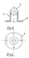
- the arrangement according to the invention consists of a butt-terminating waveguide 1, which is terminated on one side with a dielectric field transformer 2, which partially protrudes into the waveguide 2 and whose geometry is based on the reflector system used. -corresponds or is adapted to this.
- the waveguide 1 has at its other end a mounting platform 3 for subsequent assemblies 8.
- the dielectric field transformer 2 influences the E components of the alternating electromagnetic field in the direction of propagation in such a way that the original wave field at the other end of the waveguide 1 is deformed in such a way that a uniform, in particular circular expansion of the resulting radiation field of the waveguide 1 and a selectable power distribution on the reflector can be achieved. This causes a drastic increase in the efficiency of the entire arrangement.
- a preferred embodiment of the arrangement according to the invention provides the subsequent assembly 8 is not mechanically rigid with the waveguide 1 and Assembly platform 3 to connect, but rather rotatable and mechanically fixable to arrange the axis of symmetry of the reflector 6. This is combined with the special advantage that if all are retained Functionalities of the system without changing the position of the whole Antenna arrangement, in particular the reflector 6, any Polarization rotations In relation to the orthogonal arrangement of H / E vector to the normal plane of the earth - here in particular the so-called skew angle - compensate by rotating the subsequent assembly 8.
- the dielectric field transformer 2 also has the advantage that that for a wide range, the field influence is almost is uniform and at the same time a transformation of the waveguide wave mode in the free space mode is realized, making the arrangement more dielectric Field transformer 2 / waveguide 1 without repercussions on a subsequent system can be connected.
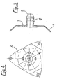
- FIG. 3 shows an arrangement according to the invention with the holder 4 shown here folded in for the accommodation of a reflector, the dielectric field transformer 2 and the mounting platform 3 provided for subsequent modules.
- FIG. 4 shows the rear view of this arrangement in which the mounting platform 3 is designed as an equilateral triangular surface 5 in order to minimize shadowing in the mirror.
- FIG. 5 shows the arrangement according to the invention with the reflector mounted.
- the subreflector with a circular aperture 6 is mounted on the brackets 4 by means of the supports 7.
- the subsequent assemblies 8 are fastened to the assembly platform 3 by means of a screw connection.
- the arrangement according to the invention is positioned in the axis of rotation of the reflector 6 and with the dielectric field transformer 2 at the level of the focal point of the reflector 6.
- a carrier board 9 is arranged in the vicinity of the dielectric field transformer 2 by means of screwed-on spacers 11.
- the dielectric carrier board 9 has a bore 12 with a diameter suitable for the dielectric field transformer 2 at the location of the field transformer 2 and is arranged plane-parallel to the mounting platform 3 without a direct mechanical or electrical connection to the dielectric field transformer 2.
- the dielectric carrier board 9, on which the passive radiator components and switching elements 10 are arranged, has the effect that the source field originating from the dielectric field transformer 2 is only slightly influenced, due to the openings in the dielectric carrier board 9, with the result that the penetrating one Field and thus the entire antenna arrangement are only slightly attenuated and thus extremely high efficiency is still available.
- a further advantage of this embodiment of the arrangement is that simple mechanical arrangement options for different antenna arrangements allow both the optimum illumination and thus the high efficiency of the entire antenna arrangement to be achieved while at the same time influencing the radiation characteristic, which in particular leads to a significant reduction in the necessary reflector area 6 leads conventional beam swiveling systems.
- FIG. 6 shows the dielectric carrier 9 in a top view. This is fastened to the mounting platform 3 with the screwable spacers 11.
- the dielectric carrier 9 contains in its center a circular bore 12, the diameter of which corresponds to the dielectric field transformer 2.
- Parasitic (passive) radiators with switching components 10 are arranged around the bore 12 of the dielectric carrier 9. In FIG. 6 , these are arranged, for example, in a uniform distribution at an angle of 90 ° in each case, the elements each consisting of a pair of radiators which are positioned orthogonally to one another.
- a control block 13, consisting of standard components, is arranged on the dielectric carrier 9 and takes over the control of the switching components. The control block is connected with a cable 14 to further subsequent assemblies.
Landscapes
- Aerials With Secondary Devices (AREA)
- Variable-Direction Aerials And Aerial Arrays (AREA)
- Waveguide Aerials (AREA)
- Details Of Aerials (AREA)
- Organic Low-Molecular-Weight Compounds And Preparation Thereof (AREA)
- Acyclic And Carbocyclic Compounds In Medicinal Compositions (AREA)
Applications Claiming Priority (3)
| Application Number | Priority Date | Filing Date | Title |
|---|---|---|---|
| DE20107294U DE20107294U1 (de) | 2001-04-21 | 2001-04-21 | Anordnung zur Erregung einer zentralfokussierten Reflektorantenne |
| DE20107294U | 2001-04-21 | ||
| PCT/DE2002/001511 WO2002087018A1 (de) | 2001-04-21 | 2002-04-19 | Anordnung zur erregung einer zentralfokussierten reflektorantenne |
Publications (2)
| Publication Number | Publication Date |
|---|---|
| EP1384287A1 EP1384287A1 (de) | 2004-01-28 |
| EP1384287B1 true EP1384287B1 (de) | 2004-08-04 |
Family
ID=7956297
Family Applications (1)
| Application Number | Title | Priority Date | Filing Date |
|---|---|---|---|
| EP02735053A Expired - Lifetime EP1384287B1 (de) | 2001-04-21 | 2002-04-19 | Anordnung zur erregung einer zentralfokussierten reflektorantenne |
Country Status (15)
| Country | Link |
|---|---|
| US (1) | US6876335B2 (enExample) |
| EP (1) | EP1384287B1 (enExample) |
| JP (1) | JP2004527178A (enExample) |
| KR (1) | KR100896113B1 (enExample) |
| CN (1) | CN100376059C (enExample) |
| AT (1) | ATE272902T1 (enExample) |
| CA (1) | CA2444948C (enExample) |
| DE (3) | DE20107294U1 (enExample) |
| DK (1) | DK1384287T3 (enExample) |
| ES (1) | ES2225791T3 (enExample) |
| HR (1) | HRP20030859B1 (enExample) |
| IL (2) | IL158492A0 (enExample) |
| NO (1) | NO326863B1 (enExample) |
| PT (1) | PT1384287E (enExample) |
| WO (1) | WO2002087018A1 (enExample) |
Cited By (1)
| Publication number | Priority date | Publication date | Assignee | Title |
|---|---|---|---|---|
| DE102007007707A1 (de) | 2007-02-13 | 2008-08-21 | Häßner, Katrin | Anordnung zur Beeinflussung der Strahlungscharakteristik einer Reflektorantenne, insbesondere einer zentral fokussierten Reflektorantenne |
Families Citing this family (3)
| Publication number | Priority date | Publication date | Assignee | Title |
|---|---|---|---|---|
| US7301504B2 (en) | 2004-07-14 | 2007-11-27 | Ems Technologies, Inc. | Mechanical scanning feed assembly for a spherical lens antenna |
| CN110739551B (zh) * | 2019-10-29 | 2021-09-28 | Oppo广东移动通信有限公司 | 阵列透镜、透镜天线和电子设备 |
| EP4428502A1 (de) * | 2023-03-07 | 2024-09-11 | VEGA Grieshaber KG | Hohlleiter bestehend aus zwei halbschalen |
Family Cites Families (22)
| Publication number | Priority date | Publication date | Assignee | Title |
|---|---|---|---|---|
| US451969A (en) * | 1891-05-12 | Lock-hinge | ||
| US91371A (en) * | 1869-06-15 | Improvement in fur collars | ||
| US684952A (en) * | 1899-02-27 | 1901-10-22 | Us Electric Signal Company | Street-railway signaling system. |
| US812096A (en) * | 1905-03-27 | 1906-02-06 | Union Tank Line Company | Railroad tank-car. |
| US3618090A (en) * | 1960-04-05 | 1971-11-02 | Us Navy | Radar |
| BE790507A (fr) * | 1971-10-26 | 1973-04-25 | Emerson Electric Co | Robinet a gaz |
| US3911440A (en) * | 1971-11-08 | 1975-10-07 | Mitsubishi Electric Corp | Antenna feed system |
| US4274097A (en) * | 1975-03-25 | 1981-06-16 | The United States Of America As Represented By The Secretary Of The Navy | Embedded dielectric rod antenna |
| US4554552A (en) * | 1981-12-21 | 1985-11-19 | Gamma-F Corporation | Antenna feed system with closely coupled amplifier |
| US4684952A (en) * | 1982-09-24 | 1987-08-04 | Ball Corporation | Microstrip reflectarray for satellite communication and radar cross-section enhancement or reduction |
| US4673945A (en) * | 1984-09-24 | 1987-06-16 | Alpha Industries, Inc. | Backfire antenna feeding |
| JPH01264004A (ja) * | 1988-04-14 | 1989-10-20 | Maspro Denkoh Corp | 2周波受信アンテナ |
| FI912234A0 (fi) | 1988-11-14 | 1991-05-08 | Motson & Co Ltd | Mottagningsanordning foer mikrovaogssignaler. |
| EP0527569A1 (en) | 1991-07-29 | 1993-02-17 | Gec-Marconi Limited | Microwave antenna |
| DE4223138A1 (de) | 1991-12-21 | 1993-06-24 | Telefunken Systemtechnik | Doppelreflektorantenne |
| US5451969A (en) * | 1993-03-22 | 1995-09-19 | Raytheon Company | Dual polarized dual band antenna |
| US5812096A (en) * | 1995-10-10 | 1998-09-22 | Hughes Electronics Corporation | Multiple-satellite receive antenna with siamese feedhorn |
| GB2314688A (en) | 1996-06-26 | 1998-01-07 | Marconi Gec Ltd | Hollow waveguide antenna |
| EP0859427B1 (en) * | 1997-02-14 | 2006-06-21 | Andrew A.G. | Dual-reflector microwave antenna |
| US6091371A (en) * | 1997-10-03 | 2000-07-18 | Motorola, Inc. | Electronic scanning reflector antenna and method for using same |
| GB9811850D0 (en) * | 1998-06-02 | 1998-07-29 | Cambridge Ind Ltd | Antenna feeds |
| US6047718A (en) * | 1999-04-01 | 2000-04-11 | Emersonelectric Co. | Solenoid valve having coaxial armatures in a single coil design |
-
2001
- 2001-04-21 DE DE20107294U patent/DE20107294U1/de not_active Expired - Lifetime
-
2002
- 2002-04-19 PT PT02735053T patent/PT1384287E/pt unknown
- 2002-04-19 KR KR1020037013703A patent/KR100896113B1/ko not_active Expired - Fee Related
- 2002-04-19 EP EP02735053A patent/EP1384287B1/de not_active Expired - Lifetime
- 2002-04-19 IL IL15849202A patent/IL158492A0/xx unknown
- 2002-04-19 DE DE10291770T patent/DE10291770D2/de not_active Expired - Fee Related
- 2002-04-19 DE DE50200764T patent/DE50200764D1/de not_active Expired - Lifetime
- 2002-04-19 DK DK02735053T patent/DK1384287T3/da active
- 2002-04-19 WO PCT/DE2002/001511 patent/WO2002087018A1/de not_active Ceased
- 2002-04-19 JP JP2002584429A patent/JP2004527178A/ja active Pending
- 2002-04-19 HR HR20030859A patent/HRP20030859B1/xx not_active IP Right Cessation
- 2002-04-19 US US10/475,543 patent/US6876335B2/en not_active Expired - Fee Related
- 2002-04-19 CA CA2444948A patent/CA2444948C/en not_active Expired - Fee Related
- 2002-04-19 CN CNB028086031A patent/CN100376059C/zh not_active Expired - Fee Related
- 2002-04-19 ES ES02735053T patent/ES2225791T3/es not_active Expired - Lifetime
- 2002-04-19 AT AT02735053T patent/ATE272902T1/de active
-
2003
- 2003-10-20 IL IL158492A patent/IL158492A/en not_active IP Right Cessation
- 2003-10-20 NO NO20034685A patent/NO326863B1/no not_active IP Right Cessation
Cited By (2)
| Publication number | Priority date | Publication date | Assignee | Title |
|---|---|---|---|---|
| DE102007007707A1 (de) | 2007-02-13 | 2008-08-21 | Häßner, Katrin | Anordnung zur Beeinflussung der Strahlungscharakteristik einer Reflektorantenne, insbesondere einer zentral fokussierten Reflektorantenne |
| WO2008098570A1 (de) | 2007-02-13 | 2008-08-21 | Häßner, Katrin | Anordnung zur beeinflussung der strahlungscharakteristik einer reflektorantenne, insbesondere einer zentralfokussierten reflektorantenne |
Also Published As
| Publication number | Publication date |
|---|---|
| DE20107294U1 (de) | 2001-08-23 |
| KR20040004593A (ko) | 2004-01-13 |
| ATE272902T1 (de) | 2004-08-15 |
| NO20034685L (no) | 2003-11-28 |
| NO20034685D0 (no) | 2003-10-20 |
| CA2444948C (en) | 2010-03-16 |
| CN1520630A (zh) | 2004-08-11 |
| PT1384287E (pt) | 2004-11-30 |
| EP1384287A1 (de) | 2004-01-28 |
| CN100376059C (zh) | 2008-03-19 |
| DE10291770D2 (en) | 2004-04-15 |
| JP2004527178A (ja) | 2004-09-02 |
| HRP20030859A2 (en) | 2005-08-31 |
| DK1384287T3 (da) | 2004-11-22 |
| HRP20030859B1 (en) | 2008-04-30 |
| IL158492A (en) | 2009-08-03 |
| WO2002087018A1 (de) | 2002-10-31 |
| KR100896113B1 (ko) | 2009-05-07 |
| DE50200764D1 (de) | 2004-09-09 |
| NO326863B1 (no) | 2009-03-02 |
| US6876335B2 (en) | 2005-04-05 |
| US20040130498A1 (en) | 2004-07-08 |
| ES2225791T3 (es) | 2005-03-16 |
| IL158492A0 (en) | 2004-05-12 |
| CA2444948A1 (en) | 2002-10-31 |
Similar Documents
| Publication | Publication Date | Title |
|---|---|---|
| EP2870658B1 (de) | Antennensystem zur breitbandigen satellitenkommunikation im ghz frequenzbereich mit hornstrahlern mit geometrischen konstriktionen | |
| DE69613244T2 (de) | Planare gruppenantenne für zwei frequenzen | |
| DE2628713C2 (de) | Rotationssymmetrische Zweispiegelantenne | |
| DE102016207434B4 (de) | Antennenvorrichtung | |
| DE69809704T2 (de) | Antennen-Tragstruktur | |
| DE69202160T2 (de) | Strahlerstruktur einer ebenen Antenne. | |
| EP3262713A1 (de) | Reflektor mit einer elektronischen schaltung und antennenvorrichtung mit einem reflektor | |
| DE4003385A1 (de) | Antennenkombination | |
| EP1616366A2 (de) | Fahrzeug-mobilfunkhalterung | |
| EP1678787A1 (de) | Vorrichtung sowie verfahren zum abstrahlen und/oder zum empfangen von elektromagnetischer strahlung | |
| DE602004009404T2 (de) | Antennenvorrichtung | |
| DE69205423T2 (de) | Antennensystem für funkwellen. | |
| DE102006003402B4 (de) | Kompakte Antennenvorrichtung mit zirkularpolarisierter Wellenabstrahlung | |
| DE2800101A1 (de) | Strahler fuer eine antenne, u.a. fuer satellitensignale | |
| EP1384287B1 (de) | Anordnung zur erregung einer zentralfokussierten reflektorantenne | |
| DE2925063C2 (de) | Radarantenne mit integrierter IFF-Antenne | |
| EP1606853A1 (de) | Antennenkoppler und halterung für mobilfunkendgeräte | |
| DE69408303T2 (de) | Antennensystem | |
| EP2118963B1 (de) | Anordnung zur beeinflussung der strahlungscharakteristik einer reflektorantenne, insbesondere einer zentralfokussierten reflektorantenne | |
| DE10313498A1 (de) | Antennenkoppler und Halterung für Mobilfunkendgeräte | |
| EP1769564B1 (de) | Vorrichtung und verfahren zum senden/empfangen elektromagnetischer hf-signale | |
| DE10249221A1 (de) | Funkkommunikationsgerät sowie zugehörige Koppelstruktur aus mindestens einer Leiterplatte und mindestens einer daran angekoppelten Flachantenne | |
| DE2752680A1 (de) | Richtantenne fuer sehr kurze elektromagnetische wellen | |
| DE19928943A1 (de) | Richtkoppler mit einstellbarer Koppeldämpfung | |
| DE69836674T2 (de) | Ebene Antenne und tragbares Funkgerät mit einer derartigen Antenne |
Legal Events
| Date | Code | Title | Description |
|---|---|---|---|
| PUAI | Public reference made under article 153(3) epc to a published international application that has entered the european phase |
Free format text: ORIGINAL CODE: 0009012 |
|
| 17P | Request for examination filed |
Effective date: 20031117 |
|
| AK | Designated contracting states |
Kind code of ref document: A1 Designated state(s): AT BE CH CY DE DK ES FI FR GB GR IE IT LI LU MC NL PT SE TR |
|
| AX | Request for extension of the european patent |
Extension state: AL LT LV MK RO SI |
|
| GRAP | Despatch of communication of intention to grant a patent |
Free format text: ORIGINAL CODE: EPIDOSNIGR1 |
|
| GRAS | Grant fee paid |
Free format text: ORIGINAL CODE: EPIDOSNIGR3 |
|
| GRAA | (expected) grant |
Free format text: ORIGINAL CODE: 0009210 |
|
| AK | Designated contracting states |
Kind code of ref document: B1 Designated state(s): AT BE CH CY DE DK ES FI FR GB GR IE IT LI LU MC NL PT SE TR |
|
| PG25 | Lapsed in a contracting state [announced via postgrant information from national office to epo] |
Ref country code: GB Free format text: LAPSE BECAUSE OF FAILURE TO SUBMIT A TRANSLATION OF THE DESCRIPTION OR TO PAY THE FEE WITHIN THE PRESCRIBED TIME-LIMIT Effective date: 20040804 |
|
| REG | Reference to a national code |
Ref country code: GB Ref legal event code: FG4D Free format text: NOT ENGLISH |
|
| REG | Reference to a national code |
Ref country code: CH Ref legal event code: EP |
|
| REG | Reference to a national code |
Ref country code: IE Ref legal event code: FG4D Free format text: GERMAN |
|
| REF | Corresponds to: |
Ref document number: 50200764 Country of ref document: DE Date of ref document: 20040909 Kind code of ref document: P |
|
| REG | Reference to a national code |
Ref country code: CH Ref legal event code: NV Representative=s name: R. A. EGLI & CO. PATENTANWAELTE |
|
| REG | Reference to a national code |
Ref country code: DK Ref legal event code: T3 |
|
| REG | Reference to a national code |
Ref country code: SE Ref legal event code: TRGR |
|
| REG | Reference to a national code |
Ref country code: PT Ref legal event code: SC4A Free format text: AVAILABILITY OF NATIONAL TRANSLATION Effective date: 20041013 |
|
| REG | Reference to a national code |
Ref country code: GR Ref legal event code: EP Ref document number: 20040403609 Country of ref document: GR |
|
| LTIE | Lt: invalidation of european patent or patent extension |
Effective date: 20040804 |
|
| GBT | Gb: translation of ep patent filed (gb section 77(6)(a)/1977) |
Effective date: 20050216 |
|
| REG | Reference to a national code |
Ref country code: ES Ref legal event code: FG2A Ref document number: 2225791 Country of ref document: ES Kind code of ref document: T3 |
|
| ET | Fr: translation filed | ||
| PLBE | No opposition filed within time limit |
Free format text: ORIGINAL CODE: 0009261 |
|
| STAA | Information on the status of an ep patent application or granted ep patent |
Free format text: STATUS: NO OPPOSITION FILED WITHIN TIME LIMIT |
|
| 26N | No opposition filed |
Effective date: 20050506 |
|
| REG | Reference to a national code |
Ref country code: DE Ref legal event code: 8364 Ref document number: 50200764 Country of ref document: DE |
|
| PGFP | Annual fee paid to national office [announced via postgrant information from national office to epo] |
Ref country code: ES Payment date: 20100420 Year of fee payment: 9 |
|
| PGFP | Annual fee paid to national office [announced via postgrant information from national office to epo] |
Ref country code: CY Payment date: 20100414 Year of fee payment: 9 |
|
| PG25 | Lapsed in a contracting state [announced via postgrant information from national office to epo] |
Ref country code: IT Free format text: LAPSE BECAUSE OF NON-PAYMENT OF DUE FEES Effective date: 20100419 |
|
| PGFP | Annual fee paid to national office [announced via postgrant information from national office to epo] |
Ref country code: TR Payment date: 20110422 Year of fee payment: 10 Ref country code: MC Payment date: 20110428 Year of fee payment: 10 Ref country code: IE Payment date: 20110427 Year of fee payment: 10 Ref country code: PT Payment date: 20110414 Year of fee payment: 10 Ref country code: LU Payment date: 20110512 Year of fee payment: 10 Ref country code: GR Payment date: 20110429 Year of fee payment: 10 Ref country code: SE Payment date: 20110429 Year of fee payment: 10 Ref country code: FR Payment date: 20110516 Year of fee payment: 10 |
|
| PGRI | Patent reinstated in contracting state [announced from national office to epo] |
Ref country code: IT Effective date: 20110616 |
|
| PGFP | Annual fee paid to national office [announced via postgrant information from national office to epo] |
Ref country code: GB Payment date: 20110413 Year of fee payment: 10 Ref country code: AT Payment date: 20110430 Year of fee payment: 10 Ref country code: NL Payment date: 20110429 Year of fee payment: 10 Ref country code: BE Payment date: 20110506 Year of fee payment: 10 Ref country code: FI Payment date: 20110428 Year of fee payment: 10 Ref country code: DK Payment date: 20110502 Year of fee payment: 10 |
|
| PGFP | Annual fee paid to national office [announced via postgrant information from national office to epo] |
Ref country code: IT Payment date: 20110428 Year of fee payment: 10 |
|
| PGFP | Annual fee paid to national office [announced via postgrant information from national office to epo] |
Ref country code: CH Payment date: 20110726 Year of fee payment: 10 |
|
| REG | Reference to a national code |
Ref country code: ES Ref legal event code: FD2A Effective date: 20120604 |
|
| PG25 | Lapsed in a contracting state [announced via postgrant information from national office to epo] |
Ref country code: ES Free format text: LAPSE BECAUSE OF NON-PAYMENT OF DUE FEES Effective date: 20110420 |
|
| REG | Reference to a national code |
Ref country code: PT Ref legal event code: MM4A Free format text: LAPSE DUE TO NON-PAYMENT OF FEES Effective date: 20121019 |
|
| BERE | Be: lapsed |
Owner name: *WOTZEL FRANK E. Effective date: 20120430 |
|
| REG | Reference to a national code |
Ref country code: DE Ref legal event code: R119 Ref document number: 50200764 Country of ref document: DE Ref country code: DE Ref legal event code: R409 Ref document number: 50200764 Country of ref document: DE |
|
| REG | Reference to a national code |
Ref country code: NL Ref legal event code: V1 Effective date: 20121101 |
|
| REG | Reference to a national code |
Ref country code: DK Ref legal event code: EBP |
|
| PG25 | Lapsed in a contracting state [announced via postgrant information from national office to epo] |
Ref country code: MC Free format text: LAPSE BECAUSE OF NON-PAYMENT OF DUE FEES Effective date: 20120430 |
|
| REG | Reference to a national code |
Ref country code: CH Ref legal event code: PL |
|
| REG | Reference to a national code |
Ref country code: SE Ref legal event code: EUG |
|
| REG | Reference to a national code |
Ref country code: AT Ref legal event code: MM01 Ref document number: 272902 Country of ref document: AT Kind code of ref document: T Effective date: 20120419 |
|
| GBPC | Gb: european patent ceased through non-payment of renewal fee |
Effective date: 20120419 |
|
| REG | Reference to a national code |
Ref country code: DE Ref legal event code: R409 Ref document number: 50200764 Country of ref document: DE |
|
| REG | Reference to a national code |
Ref country code: IE Ref legal event code: MM4A |
|
| REG | Reference to a national code |
Ref country code: FR Ref legal event code: ST Effective date: 20121228 |
|
| REG | Reference to a national code |
Ref country code: GR Ref legal event code: ML Ref document number: 20040403609 Country of ref document: GR Effective date: 20121102 |
|
| REG | Reference to a national code |
Ref country code: DE Ref legal event code: R082 Ref document number: 50200764 Country of ref document: DE Representative=s name: NEUMANN, GUENTER, DIPL.-ING.OEC., DE Ref country code: DE Ref legal event code: R082 Ref document number: 50200764 Country of ref document: DE Representative=s name: MUELLER, WOLFRAM, DIPL.-PHYS. DR.IUR., DE Ref country code: DE Ref legal event code: R082 Ref document number: 50200764 Country of ref document: DE Representative=s name: MUELLER, WOLFRAM, DIPL.-PHYS. DR. JUR., DE |
|
| PG25 | Lapsed in a contracting state [announced via postgrant information from national office to epo] |
Ref country code: CH Free format text: LAPSE BECAUSE OF NON-PAYMENT OF DUE FEES Effective date: 20120430 Ref country code: FI Free format text: LAPSE BECAUSE OF NON-PAYMENT OF DUE FEES Effective date: 20120419 Ref country code: IE Free format text: LAPSE BECAUSE OF NON-PAYMENT OF DUE FEES Effective date: 20120419 Ref country code: GB Free format text: LAPSE BECAUSE OF FAILURE TO SUBMIT A TRANSLATION OF THE DESCRIPTION OR TO PAY THE FEE WITHIN THE PRESCRIBED TIME-LIMIT Effective date: 20120419 Ref country code: BE Free format text: LAPSE BECAUSE OF NON-PAYMENT OF DUE FEES Effective date: 20120430 Ref country code: LI Free format text: LAPSE BECAUSE OF NON-PAYMENT OF DUE FEES Effective date: 20120430 Ref country code: CY Free format text: LAPSE BECAUSE OF NON-PAYMENT OF DUE FEES Effective date: 20120419 Ref country code: AT Free format text: LAPSE BECAUSE OF NON-PAYMENT OF DUE FEES Effective date: 20120419 |
|
| PG25 | Lapsed in a contracting state [announced via postgrant information from national office to epo] |
Ref country code: IT Free format text: LAPSE BECAUSE OF NON-PAYMENT OF DUE FEES Effective date: 20120419 Ref country code: PT Free format text: LAPSE BECAUSE OF NON-PAYMENT OF DUE FEES Effective date: 20121019 Ref country code: GR Free format text: LAPSE BECAUSE OF NON-PAYMENT OF DUE FEES Effective date: 20121102 Ref country code: FR Free format text: LAPSE BECAUSE OF NON-PAYMENT OF DUE FEES Effective date: 20120430 Ref country code: SE Free format text: LAPSE BECAUSE OF NON-PAYMENT OF DUE FEES Effective date: 20120420 |
|
| PG25 | Lapsed in a contracting state [announced via postgrant information from national office to epo] |
Ref country code: NL Free format text: LAPSE BECAUSE OF NON-PAYMENT OF DUE FEES Effective date: 20121101 |
|
| PG25 | Lapsed in a contracting state [announced via postgrant information from national office to epo] |
Ref country code: DK Free format text: LAPSE BECAUSE OF NON-PAYMENT OF DUE FEES Effective date: 20120430 |
|
| PG25 | Lapsed in a contracting state [announced via postgrant information from national office to epo] |
Ref country code: LU Free format text: LAPSE BECAUSE OF NON-PAYMENT OF DUE FEES Effective date: 20120419 Ref country code: TR Free format text: LAPSE BECAUSE OF NON-PAYMENT OF DUE FEES Effective date: 20120419 |
|
| REG | Reference to a national code |
Ref country code: DE Ref legal event code: R082 Ref document number: 50200764 Country of ref document: DE Representative=s name: MUELLER, WOLFRAM, DIPL.-PHYS. DR.IUR., DE Ref country code: DE Ref legal event code: R082 Ref document number: 50200764 Country of ref document: DE Representative=s name: MUELLER, WOLFRAM, DIPL.-PHYS. DR. JUR., DE |
|
| PGFP | Annual fee paid to national office [announced via postgrant information from national office to epo] |
Ref country code: DE Payment date: 20170427 Year of fee payment: 16 |
|
| REG | Reference to a national code |
Ref country code: DE Ref legal event code: R119 Ref document number: 50200764 Country of ref document: DE |
|
| PG25 | Lapsed in a contracting state [announced via postgrant information from national office to epo] |
Ref country code: DE Free format text: LAPSE BECAUSE OF NON-PAYMENT OF DUE FEES Effective date: 20181101 |