EP1384046B1 - Digital camera for and method of obtaining overlapping images - Google Patents
Digital camera for and method of obtaining overlapping images Download PDFInfo
- Publication number
- EP1384046B1 EP1384046B1 EP02769388.6A EP02769388A EP1384046B1 EP 1384046 B1 EP1384046 B1 EP 1384046B1 EP 02769388 A EP02769388 A EP 02769388A EP 1384046 B1 EP1384046 B1 EP 1384046B1
- Authority
- EP
- European Patent Office
- Prior art keywords
- sub
- image
- large area
- array
- pixels
- Prior art date
- Legal status (The legal status is an assumption and is not a legal conclusion. Google has not performed a legal analysis and makes no representation as to the accuracy of the status listed.)
- Expired - Lifetime
Links
Images


Classifications
-
- G—PHYSICS
- G06—COMPUTING OR CALCULATING; COUNTING
- G06T—IMAGE DATA PROCESSING OR GENERATION, IN GENERAL
- G06T3/00—Geometric image transformations in the plane of the image
- G06T3/40—Scaling of whole images or parts thereof, e.g. expanding or contracting
- G06T3/4038—Image mosaicing, e.g. composing plane images from plane sub-images
-
- G—PHYSICS
- G01—MEASURING; TESTING
- G01C—MEASURING DISTANCES, LEVELS OR BEARINGS; SURVEYING; NAVIGATION; GYROSCOPIC INSTRUMENTS; PHOTOGRAMMETRY OR VIDEOGRAMMETRY
- G01C11/00—Photogrammetry or videogrammetry, e.g. stereogrammetry; Photographic surveying
- G01C11/02—Picture taking arrangements specially adapted for photogrammetry or photographic surveying, e.g. controlling overlapping of pictures
Definitions
- This invention is related generally to photogrammetry and more specifically to large format digital cameras for acquiring images of large area objects or large areas of large objects, such as aerial images of portions of the surface of the earth.
- the camera could have a larger field of view, such as a wider angle lens, so that it would not have to be backed so far away from the mountain to fit the view of the mountain within the field of view of the lens, some enhancement of details, i.e., higher resolution, could be obtained.
- Such wide angle lenses sometimes called "fisheye” lenses, are well-known, but they also distort the image---magnifying portions in the middle and diminishing marginal portions of the image.
- Resolution obtainable by digital cameras is also limited by the sizes of photodetector arrays.
- Images are detected in digital cameras by focusing light on an image onto an array of photodetector devices, such as charge-coupled devices (CCD's).
- CCD's charge-coupled devices
- Each photodetector in the array produces an electric signal, the voltage or current of which is a function of the intensity of all the light that is focused onto that photodetector.
- the electric signal (voltage or current) level produced by that photodetector will be indicative of the average light energy reflected from the entire house.
- the light reflected from the house could be focused on an array of tens or even hundreds or thousands of individual photodetectors, so that light reflected from a window, for example, is focused on one or more individual photodetectors, while light reflected from doors, walls, and different roof sections of the house could be focused on other respective multitudes of individual photodetectors, then individual electric signals indicative of light energies reflected from each of those various parts or features of the house would be available for producing more details of the house in the image, i.e., there would be higher resolution in the picture.
- a problem faced by digital camera manufacturers is that large photodetector arrays, to the extent they are commercially available, are not inexpensive. Therefore, most camera designers and manufacturers are limited to commonly available photodetector arrays. Rectangular array sizes of about 1,000 x 1,000, i.e., about 1,000,000, photodetectors are now fairly common and readily available, while arrays of 5,000 x 5,000, i.e., about 25,000,000 photodetectors, or more are considered to be "large” and expensive. These array sizes are impressive compared to only a few years ago, and sizes of photodetector arrays will no doubt continue to grow in coming years. They are, none the less, still limited.
- Scanning cameras are ones in which a linear array of photodetectors are moved in the stationary image plane of a camera to cover the entire image format or view.
- a similar effect, but different method, is to move (rotate) the camera, usually in an arc about an axis that extends through the lens and is parallel to the scene or object and to the image plane.
- Cameras that use this latter technique of scanning the object by rotating the camera are called panoramic cameras.
- Both scanning cameras and panoramic cameras, as described above also require that the object does not move in relation to the location of the camera, and vice versa, while the object is being scanned to collect the image.
- "push-broom” scanning the entire camera, including both the lens and the linear array of photodetectors, is mounted on the satellite and moves with the satellite in relation to the object, which is the earth's (or other planet or moon) surface.
- the image of the object (earth or other planet or moon surface), therefore, is collected in individual linear paths corresponding to the linear array of photodetectors being swept over the object, and a plurality of such paths are then assembled together to produce the image.
- the object (earth, etc.) must not “move” as it is being scanned, i.e., the satellite with the camera remains a fixed distance from the center of mass of the earth during the satellite's movement and scan of the earth's surface.
- the problem with such "push-broom” scanning is that it is difficult to know the camera path accurately, which results in a notorious lack of accuracy in stereo measurements or mensuration in the resulting images.
- a point on the ground in the path of the multiple "push-broom" image acquisitions is imaged as many times as there are linear arrays in the camera.
- a problem is that each image line has a separate perspective center, so the resulting composite image of the object has many perspective centers.
- PCT Patent Cooperation Treaty
- This camera is also mounted on an airplane or spacecraft, and, as it flies, the image taking is repeated rapidly so that spaces between images acquired by individual detectors in a group are filled or partially filled by images acquired by the next row of detectors in the group, etc., until the three group images are filled and synthesized together from the individual detectors in the group.
- This system requires the motion of the airplane or spacecraft, and it cannot be used to image a moving object. It also has the problem of multiple perspective centers.
- US 5,864,133 discloses a cost-effective optical device used for converting a photo-image into electronic signals with high resolution.
- the optical device includes a plurality of focusing units for receiving a plurality of sections of the photo-image respectively, and generating a plurality of corresponding focused image sections wherein the focusing units are mounted in specific locations for focusing the plurality of sections of the photo-image through various light paths and at various distance, and the plurality of corresponding focused image sections are magnified with the same ratio, a photoelectric conversion unit for sequentially converting the plurality of corresponding focused image sections into the electronic signals, and a light-reflecting unit mounted between the plurality of focusing units and the photoelectric conversion unit for sequentially transmitting the plurality of corresponding focused image sections to the photoelectric conversion unit.
- US 4 383 170 A discloses a method of acquiring a large area image by acquiring a plurality of small area images that are acquired by sequentially focusing multiple non-overlapping portions of the large area through a compound lens system onto a photosensitive array.
- a general object of this invention is to provide a method and camera apparatus that can produce high resolution, large format, digital images of large area objects.
- a more specific object of the present invention is to provide a large format, digital camera system and method for acquiring large format, digital images of large area objects, but without the requirement and costs of large, expensive, detector arrays.
- Another object of the present invention is to provide a large format, digital camera system and method for acquiring large format, digital images of objects that are either moving or stationary.
- Another specific object of the present invention is to provide a method and camera apparatus for acquiring instantaneous, large format, digital images of an object so that movement of the object or of the camera apparatus does not cause blurring or distortion of the images.
- Still another object of the present invention is to provide a method and camera apparatus for acquiring large format, digital images of a large area object inexpensively enough that there can be a degree of redundancy in order to produce high quality, large format, digital images without having to rely on flawless detector arrays.
- Yet another object of the present invention is to provide a method and camera apparatus for acquiring large format, digital images of large area objects with fast and efficient digital data read-out and processing.
- a further object of the present invention is to provide a method and camera apparatus with high resolution, wide angle geometry for a wide field of view and for good stereo digital imaging.
- a still further object of the present invention is to provide a method and digital camera' apparatus for producing a large image format that has a single perspective center.
- a method of this invention may comprise digital camera systems in which two-dimensional arrays are exposed to multiple portions or sub-areas of large area objects to acquire overlapping sub-images of such sub-areas.
- the digital sub-images can then be pieced or stitched together in a digital mosaic to form a digital macro-image of the large area object.
- the sub-images can be acquired by a single, two-dimensional, detector array and exposed sequentially to the different sub-areas by different lens systems.
- clusters comprising multiple, spaced apart, two-dimensional detector arrays are exposed to different sub-areas of the large area object by a single lens system either sequentially or simultaneously to acquire the overlapping sub-images.
- a large format, digital camera system comprises more than one sub-camera system, and each sub-camera system has its own lens system with at least one detector array in the focal plane of each lens system.
- the lens systems have the same focal length and are mounted closely together in a manner that makes their focal planes coplanar and their optical exes parallel to each other.
- the detector array(s) of the different sub-cameras are exposed by the respective single lens systems of the sub-cameras to overlapping sub-areas of large area objects so that sub-images acquired by different sub-cameras have overlapping areas to facilitate piecing or stitching them together into a seamless macro-image of the large area object.
- the shutters and image acquisition systems of the respective sub-cameras can be actuated in timed sequence coordinated with the speed of movement to make the perspective centers of the sub-camera images match the perspective centers of the other sub-camera images. Therefore, when the macro-image is pieced or stitched together from the sub-images, it has a single perspective center. If it does not move, the shutters and image acquisition systems can be actuated either sequentially or simultaneously, but the macro-image will have a plurality of perspective centers, i.e., one perspective center for the images acquired by each sub-camera system. Thus, a large format, digital camera comprising four sub-camera systems will, if not moving with shutters actuating in the timed sequence, have four perspective centers.
- More detector arrays can be added to each sub-camera system to increase the format size of the large format, digital camera system, or the detector arrays can be larger to increase the format size without adding more sub-cameras. Of course, adding more sub-cameras can also increase format size.
- the sub-image read-out from the various detector arrays is accomplished simultaneously in a parallel manner for speed.
- Digital correlated double sampling is used to convert the individual photodetector output signals twice per pixel using an analog to digital converter at the double sampling rate and to perform the subtraction of the residual reset signal to the actual light exposed signal in the digital domain.
- An accelerometer on a dampened camera carrier platform outputs signals during sub-image acquisition, which are used to evaluate vibration or movement magnitude. Sub-images are rejected and the shutter is re-actuated to re-acquire images in short order when the magnitude of vibrations or movement is large enough to degrade the sub-image quality.
- FIG. 1 One of the simpler, yet effective, large format, digital camera systems of this invention is illustrated diagrammatically in Figure 1 .
- the large area camera system 10 in figure 1 is represented by a plurality of lens systems 12, 14, 16, 18, all of which have the same focal length F and are positioned in a common plane P, and a photodetector array 20 positioned in the focal plane of the lens systems 12, 14, 16, 18, i.e., at a distance F from the plane P.
- the photodetector array 20 is connected electrically by suitable conductors 22 to a control circuit 24, which includes at least a microprocessor, input/output circuitry, memory, and power supply for driving the photodetector array 20, reading sub-image data out of the photodetector array 20, and storing such sub-image data.
- control circuit 24 includes at least a microprocessor, input/output circuitry, memory, and power supply for driving the photodetector array 20, reading sub-image data out of the photodetector array 20, and storing such sub-image data.
- Other data processing functions such as combining sub-images and/or image display functions, can be accomplished in the camera system 20 or with other peripheral data processing equipment.
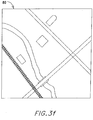
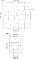
- the large format camera system 10 in Figure 1 is illustrated simplistically in the process of acquiring a large format digital image (not shown in Figure 1 ) of a large area 20 of an object 32, for example, a semi-developed geographical area on the earth's surface that includes a stream 34, railroad 36, three building structures 38, 40, 42, two cross streets 44, 46, and a bridge 48, where on cross street 46 crosses the stream 34.
- a large format digital image (not shown in Figure 1 ) of a large area 20 of an object 32, for example, a semi-developed geographical area on the earth's surface that includes a stream 34, railroad 36, three building structures 38, 40, 42, two cross streets 44, 46, and a bridge 48, where on cross street 46 crosses the stream 34.
- the components of the camera system 10, and large area 30 of the object 32 are not shown in actual sizes, proportions, or details, which would not be practical or even possible within the constraints of the drawing format, as would be understood by persons skilled in the art.
- the camera system 10 is shown with four lens systems 12, 14, 16, 18 positioned in the common plane p and configured to focus four parts of sub-areas 50, 52, 54, 56, respectively, of the large area 30 onto the detector array 20.
- any plurality of lens systems would work for purposes of this invention.
- the first lens system 12 focuses a first sub-area 50 onto the detector array 20, and then the second lens system 14 focuses a second sub-area 52 onto the detector array 20, the third lens system 16 focuses a third sub-area 54 onto the detector array 20, and the fourth lens system 18 focuses a fourth sub-area 56 onto the detector array 20, all in sequential order.
- the lens systems 12, 14, 16, 18 are set so that marginal edge portions of the sub-areas 50, 52, 54, 56 overlap each other. Therefore, such overlapping marginal edge area 60 is common to sub-areas 50, 52.
- overlapping marginal edge area 62 is common to sub-areas 50, 54
- marginal edge area 64 is common to sub-areas 52, 56
- marginal edge area 66 is common to sub-areas 54, 56.
- Each lens system 12, 14, 16, 18 includes a shutter that can be opened and closed independently of the other lens systems, so that the detector array 20 can be exposed to only one of the sub-areas 50, 52, 54, 56 at a time.
- the shutters and their actuators are not shown in Figure 1 because of drawing size constraints, but shutters and shutter actuators are well-known to persons skilled in the art, who would be able to implement them without difficulty to practice this invention. Therefore, there is no need to describe shutters in lens systems or their actuators for purposes of describing this invention.
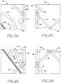
- shutter actuators are connected to the control circuit 24 by suitable electric leads or conductors 26 so that read-out of image data from the detector array 20 can be coordinated with actuation of the respective shutters in lens systems 12, 14, 16, 18, as will be described in more detail below.
- the control circuit 24 reads out the sub-image 70 ( Figure 2a ) of sub-area 50 from the detector array 20.
- the detector array 20 comprises an array of individual photodetectors, e.g., semiconductor devices that output an electric signal, the magnitude of which is dependent on the intensity of light energy incident on such photodetector. Therefore, the signal from each photodetector in the array 20 is indicative of light energy intensity from a pixel area of the sub-area 50, and the signals from all of the individual photodetectors in the array are indicative of light energy intensity from all of the pixel areas of the sub-area 50.
- the signals from the photodetectors in the detector array 20, together, are indicative of the pattern of light energy from the sub-area 50, so a sub-image 70 ( Figure 2 ) of the sub-area 50 can be produced from such signals.
- the signals are amplified, digitized, processed, and stored, as is well-known to persons skilled in the art.
- the shutter for the second lens system 14 is actuated to acquire and store a sub-image 72 ( Figure 2b ) of the sub-area 52 in digital form. Acquisitions of sub-image 74 ( Figure 2c ) of sub-area 54 and of sub-image 76 ( Figure 2d ) of sub-area 56 by lens system 16 and lens system 18, respectively, are accomplished in a similar manner.
- the read-out time for a detector array less than 5,000 x 5,000 is typically less than one second, such as about one-half a second.
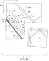
- the preferred method is to use known or calculated mechanical measurements or relationships to piece the respective sub-images 70, 72, 74, 76 together on a pixel-by-pixel basis in a common, master X-Y coordinate system and then to use software-identifiable, distinct features or parts of features in the overlapping, marginal edge areas 60, 62, 64, 66 as guide markers for final pixel adjustments to align and "stitch" together the adjacent sub-images to form the large format, macro-image 80.
- one of the sub-images for example sub-image 70, is chosen as the master sub-image, and its pixel array is chosen as the master X-Y coordinate system 82.
- the second sub-image 72 For piecing the second sub-image 72 together with the first, or master, sub-image 70, it is first joined as closely as possible with known or measured mechanical dimensions and relationships based on relative positions and orientations of the respective lens systems 12, 14 ( Figure 1 ), size of the detector array 20, distances of the lens systems 12, 14, from the detector array 20 from the lens systems 12, 14, and the like.
- This initial placement of the second sub-image 72 by its pixel array coordinate system x-y is accurate enough to get very close to registering the common features 38, 40, 44 together in the overlapping marginal edge portion 60.
- the master coordinates of pixels of distinct features 38, 40, 44 in the first sub-image 70 should be very close to the same as the coordinates for pixels of those same features 38', 40', 44' in the second sub-image 72, both of these sub-images 70, 72 are acquired with the same detector array 20 ( Figure 1 ).
- the parallaxes due to the different locations of the respective lens systems 12, 14 and other inaccuracies in measurements, lengths, and the like, cause slight variations or displacements between such features, as illustrated in Figure 3a .
- the software can identify distinct features in the overlapping marginal edge portion 60 of both sub-images 70, 72. Corners, such as Q 1 , Q 1 ', and Q 2 ', are usually easiest to identify, because of sharp light intensity difference, thus electric signal difference, between adjacent photodetectors at such corners cause larger digital value differences for adjacent pixels of the sub-images at such corners. However, other distinct features or variations in pixel values can also be located with software for this synthesizing or stitching process. Once several distinct and matching points, such as Q 1 , Q 1 ', and Q 2 ', are identified in the respective sub-images 70, 72 their coordinates can be adjusted to register with each other.
- the master X-Y coordinates of points Q 1 and Q 2 are compared to each other and their X-Y differences determined.
- the master X-Y coordinates of points Q 2 and Q 2 ' are compared and their X-Y differences determined. With that difference information, the master X-Y pixels for those points Q 1 ' and Q 2 ' of the second sub-image 52 can be adjusted to match the master X-Y coordinates of the corresponding points Q 1 and Q 2 in the first sub-image 50.
- the two sub-images 70, 72 are stitched together geometrically to form the top half 86 of the large format, macro-image, as shown in Figure 36.
- the remaining two sub-images 74, 76 can be stitched together in a similar manner, as will be described below. However, before doing so, it may be desirable to perform any radiometric adjustments necessary to match gray scales of pixels in the second sub-image 72 with those of the first sub-image 70, so that one part of the half-image 86 does not look darker or brighter than the other part.
- Such gray scale variations in this camera system 10 are usually not a significant problem, because all the digital sub-images 70, 72, 74,76 are created with the same detector array 20 ( Figure 1 ).
- radiometric adjustments can be made with software by comparing output signal intensity of at least one, but preferably more, pixels of the first sub-image 70 with matching pixels of the second sub-image 72 in the overlapping marginal edge area 60. Whatever adjustments of signal intensity is needed to make the compared pixels in the second sub-image 72 match or nearly match the corresponding pixels in the first sub-image 70 can then be applied also to the other pixels in the second sub-image.
- the third sub-image is also brought into the master X-Y coordinate system 82 based on mechanical relationships and/or measurements. Then, distinct, corresponding features or points, e.g., Q 3 , Q 3 ' and Q 4 , Q 4 ', of the upper half-image 86 and the third sub-image 74 are identified in the overlapping marginal edge area 62. Adjustments are made, as described above, to stitch the third sub-image 74 together with the upper half-image 86 to produce the three-fourth-image 88, shown in Figure 3d . Radiometric adjustments can also be made, as explained above.
- the fourth sub-image is also brought into the master X-Y coordinate system 82 based on mechanical relationships and/or measurements.
- the distinct, corresponding features or points, e.g., Q 5 , Q 5 ' and Q 6 , Q 6 ', of the three-fourths-image 88 and the fourth sub-image 76 are identified in either one or both of the overlapping marginal edge areas 64, 66. Adjustments are made, as described above, to stitch the fourth sub-image 76 together with the three-fourths-image 88 to produce the full, large format, macro-image 80, shown in Figure 3f .
- This large format, macro-image 80 is, of course, the large image of the large area object 30 in Figure 1 .
- Radiometric adjustments can also be made, as explained above. Also, if perfect registration of the points Q 5 , Q 5 ' and Q 6 Q 6 ' or other identified points in overlapping marginal edge areas 64, 66 cannot be made due to distortions or other inaccuracies in the processes of the previous stitchings of sub-images 70, 72, 74 or other causes, the software can make blending adjustments to the pixel coordinates to achieve a fit of all the sub-images 70, 72, 74,76 together into the large, macro-image 80 without concentrating any noticeable distortions.
- the large format image 80 of the large area object 30 can be acquired as described above with a readily available, normal-size detector array 20, such as a 1,000 x 1,000 array or a 2,000 x 2,000 array, instead of a very expensive, large detector array, yet the resolution is four times better than would be attainable with a conventional digital camera with such a normal-size detector array.
- the digital camera system 10 could be equipped with more lens systems to create even more sub-images and thereby make even a larger format camera for even better resolution.
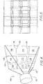
- a single lens system 102 is used to focus a large area object (not shown in Figure 4 , but similar to the large area object in Figure 1 ) onto a plurality of detector arrays, for example, the nine detector arrays 104, 106, 108, 110, 112, 114, 116, 118, 120, all positioned in the focal plane 122 of the lens system 102.
- Each of the detector arrays can be a normal size, such as 1,000 x 1,000 or 2,000 x 2,000, but such nine normal-size detector arrays 104, 106, 108, 110, 112, 114, 116, 118, 120 provides nine times more pixels than one of such arrays, thus nine times better resolution.
- Each of the plurality of detector arrays 104, 106, 108, 110, 112, 114, 116, 118, 120 produces a sub-image of a part or sub-area of the large area object, and such sub-images can be combined together in a mosaic by software to produce the large format image of the large area object.
- While such large format camera system 100 has the advantage of exposing a plurality of detector arrays 104, 106, 108, 110, 112, 114, 116, 118, 120 simultaneously to sub-areas of the large area object and the advantage of reading out sub-images from the plurality detector arrays simultaneously, for example, with parallel data processors (not shown), this approach leaves small image gaps between adjacent sub-images because of physical gaps 124, 126, 128, 130 between the detector arrays mounted adjacent each other in the focal plane 122. Such gaps cannot be avoided, because the sensitive area of each detector array 104, 106, 108, 110, 112, 114, 116, 118, 120 is always smaller than the physical size of the array unit.
- a rotation of the prism (not shown) at 90, 135, and 180 degrees would cause shifts to the left, down, and left + down, respectively.
- Each detector array 104, 106, 108, 110, 112, 114, 116, 118, 120 has its sub-image read out before the prism shift and after each prism shift.
- the read-out time is typically less than one (1) second, such as, for example, about one-half second.
- this large format camera system 150 comprises a plurality, e.g., four, connected sub-camera systems designated as 1, 2, 3, and 4.
- Each sub-camera system 1, 2, 3, 4 in the macro-camera system 150 is, itself, a large format camera system similar to the large format camera system 100 in Figure 4 , i.e., each has a plurality of detector arrays exposed to the large area object 230.
- the first sub-camera system 1 comprises a plurality (e.g., six) of detector arrays 152 positioned spaced apart from each other in the focal pane 154 of the lens system 156.
- the spaces 158 between the detector arrays 152 are preferably almost, but not quite, as long or as wide as a detector arrays 152, so that sub-images from other ones of the sub-camera systems 2, 3, and 4 with similar sized and shaped detector arrays can fill the gaps between sub-images acquired by detector arrays 152 with some overlap in the marginal edge portions for stitching together to make a large area macro-image in a manner similar to that described above for camera system 10 and as will be explained in more detail below for this camera system 150.
- each of the six detector arrays 152 of sub-camera 1 When all six of the detector arrays 152 of sub-camera 1 are exposed to the large area object 230 by lens system 156, each of the six detector arrays will create a sub-image of a part or sub-area 1' of the large area object 230 with some overlap at marginal edge portions into adjacent sub-areas, as explained above.
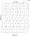
- Those sub-images acquired by the sub-camera system 1 are designated 1" in the macro-image 232 in Figure 7 .
- the large format, macro-image 230" in Figure 7 is a macro-image of the large area object 230 in Figure 6 pieced or stitched together from the sub-images 1", 2", 3", 4" acquired by all the sub-camera systems 1, 2, 3, 4.
- center 234' of the large area object 230 is the perspective center 155 of the sub-camera system 1, i.e., on the optic axis 151 of the sub-camera system 1, it is not included in any of the sub-images 1" in Figure 7 acquired by the sub-camera system 1 of Figure 6 , because the optic axis 151 extends through the focal plane 154 in a space 158 between the detector arrays 152 of sub-camera system 1.
- the other sub-camera systems 2, 3, 4 have their respective lens systems 166, 176, 186, all with the same focal length as lens system 156 of sub-camera system 1.
- the lens systems are mounted adjacent each other, preferably in a common plane, so that the optic axis 151, 161, 171, 181 of each lens system 156, 166, 176, 186, respectively, substantially parallel to the optic axes of the other lens systems.
- each sub-camera system 2, 3, 4 has one or more detector arrays 162, 172, 182, respectively mounted in the respective focal plane 164, 174, 184 of lens systems 166, 176, 186.
- sub-camera system 2 has four detector arrays 162
- sub-camera system 3 has three detector arrays 172
- sub-camera system 4 has two detector arrays 182, all positioned so that sub-images acquired by them fill gaps between sub-images acquired by sub-camera system 1 and by other sub-camera systems with some overlap in marginal edge portions to accommodate stitching sub-images together, as described above.
- One of the advantages of the large format, digital camera system of this example including, but not limited to the camera system 150 in Figure 6 , is that larger format macro-images can be acquired, if desired, by either adding more detector arrays, or using larger detector arrays, or both, without having to add more lens systems.
- the optic axes 151, 161, 171, 181 of all the sub-camera systems 1, 2, 3, 4 are substantially parallel to each other, as explained above.
- the shutters of the respective lens systems 156, 166, 176, 186 can be actuated in a timed sequence coordinated with the speed of travel, as will be explained in more detail below.
- each lens system 156, 166, 176, 186 which intersects the optic center 155, 165, 175, 185 of its respective image plane 154, 164, 174, 184, will also extend through the same center 234 of the large area object 230, so that the perspective centers 155, 165, 175, 185 of each sub-camera system 1, 2, 3, 4 is the same in order to have the corresponding image center 230" in Figure 7 the same for all the sub-images acquired by all the sub-camera systems 1, 2, 3, 4.
- the optic axis 151, 161, 171, 181 of each sub-camera system 1, 2, 3, 4 extends through the object center 234 as its respective shutter is actuated. Consequently, when the sub-images 1", 2", 3", 4" are acquired in this manner, they will all have the same perspective center 234" corresponding to the object center 234 and to the respective optic centers 155, 165, 175, 185 of the sub-cameras 1, 2, 3, 4.
- the lens systems 156, 166, 176, 186 can be mounted in a common plane 140, and the focal planes 154, 164, 174, 184 can be co-planar.
- the lens systems 156, 166, 176, 186 and their focal planes 154, 164, 174, 184 do not have to be positioned in a straight line as shown in Figure 6 , but could instead be positioned at corners of a rectangle, square, or any other pattern, but preferably coplanar and close together to minimize the distance between parallel axes.
- sub-images 1" of sub-areas 1' acquired by sub-camera system 1 are stitched together, as described above, in a mosaic with sub-images 2", 3", 4" of respective sub-areas 2', 3', 4' acquired by sub-camera systems 2, 3, 4, respectively, as shown in Figure 7 to complete the large format, macro-image 230" of large area image 230 of Figure 6 .
- digital camera system 150 can create a large format image 230" with a plurality of common, conventional size, detector arrays and with one common optical center 234". Further, this large format camera system 150 can accommodate acquisition of all the sub-images with all the detector arrays 152, 162, 172, 182 simultaneously.
- the resulting macro-image 230" of the large format camera system 150 is much like a picture or image acquired with an ordinary film-based camera or an ordinary small format digital camera.
- the object 230 can be either stationary or moving at moderate speeds in relation to the camera system 150, and the resulting large format image 230" will not be distorted any more than would be a picture or image acquired by an ordinary film-based camera or a small format digital camera.
- the large format, digital camera 150 could be used in a stationary position to make a large format, digital image of a painting or of a landscape scene, or even scenes in which an object is moving at a moderate speed, where the large format is desired for better resolution of details than can be acquired with ordinary size format digital cameras.
- an example size for each detector array 152, 162, 172, 182 may be 2,000 x 3,000 detectors. Allowing for several hundred pixel rows and columns of overlap in marginal edge areas for stitching sub-images together, as described above, will produce a large format image 230" of about 9,000 x 8,500 pixels. Different numbers and arrangements or patterns of detector arrays in sub-camera systems can be used to produce different sized macro-images.
- the macro-image 236" in Figure 8 can be produced by a first sub-camera system with twelve detector arrays, a second sub-camera system with nine detector arrays, a third sub-camera system with eight detector arrays, and a fourth sub-camera system with six detector arrays.
- these example macro-images 236" and 238" of Figures 8 and 9 are produced with a common optical center for all sub-cameras in the system.
- each of the sub-camera systems 1, 2, 3, 4 of the large format, digital camera system 150 in Figure 6 preferably has an electronically controlled shutter (not shown) but is well-known to persons skilled in the art in its lens system 156, 166, 176, 186, which can be actuated simultaneously.
- Such electronic shutter actuation signals can also be used to synchronize detector array exposure time with the shutter actuations, which is important, especially if the camera system 150 is mounted on a moving vehicle, such as an aircraft or spacecraft.
- each of the detector arrays 152, 162, 172, 182 is connected to a separate electronic data processing module, such as sensor electronics, analog electronics, digital electronics, and computer interface to produce individual data streams from the respective detector arrays 152, 162, 172, 182 to the data storage media.
- a separate electronic data processing module such as sensor electronics, analog electronics, digital electronics, and computer interface to produce individual data streams from the respective detector arrays 152, 162, 172, 182 to the data storage media.
- This preferred arrangement facilitates parallel capture of sub-image data from the individual detector arrays or of small groups of the detector arrays, which is quicker than serial or sequential read-out of data from the detector arrays (also much quicker than read-out of data from a large detector array). Such quicker read-out capability also enables shorter time intervals from one simultaneous exposure of the detector arrays to the next.
- This capability is important for any application where multiple macro-images have to be acquired quickly one after the other, such as when a path of macro-images of the earth's surface are being acquired with the camera system 150 from an airplane. Only medium accuracy is needed for the shutter synchronization for simultaneous exposure of the detector arrays 152, 162, 172, 182, because the sub-image 1", 2", 3", 4" stitching process compensates for small errors in the synchronization.
- the method and apparatus of this invention can also facilitate quick acquisition of large format, color digital images. It is conventional for photodetectors, such as charge-coupled devices (CCD's) to be arranged to produce color digital images directly. However, that approach is typically at the expense of geometric resolution. Therefore, there is a trade-off between: (i) creating color directly with a smaller area photodetector (CCD) array; or (ii) using black and white photodetectors (CCD's) along with multiple cones (lens to focal plane optical path) and color (wavelength) filters.
- CCD charge-coupled devices
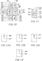
- Color information acquisition with a large format digital camera system 250 illustrated in Figure 10 is similar to the large format camera system 150 in Figures 6 - 9 , but is equipped with additional sub-camera systems, including lens and detector arrays, for color and near infrared (nir). As shown in Figure 10 , there are eight sub-camera systems 1, 2, 3, 4, r, g, b, nir. Only the light sensor surfaces of the detector arrays of the sub-camera systems are shown in Figure 10 , which is sufficient for purposes of this description, since the lens systems and other elements of the sub-camera systems can readily be understood by reference back to other embodiments and examples described above.
- the sub-camera systems 1, 2, 3, 4 of the large format, color, digital camera system have their respective detector arrays 252, 262, 272, 282 are positioned in co-planar focal planes 254, 264, 274, 284, and the respective lens systems (not shown in Figure 10 ) have the same focal lengths, as described above for camera system 150 in Figure 6 .
- optical or perspective centers 255, 265, 275, 285 for all of the sub-camera systems 1, 2, 3, 4 in Figure 10 are the same, i.e., are on the optic axes of the respective lens systems (not shown in Figure 10 ) of the respective sub-camera systems 1, 2, 3, 4 and correspond to the same center of the large area object being images (not shown in Figure 10 ), as also described above for camera system 150 in Figure 6 .
- the sub-images 262", 272", 282" of sub-areas of the large area object being imaged (not shown in Figure 10 ) produced by the detector arrays 262, 272, 282, when combined together with the sub-images 252" of sub-areas of the large area image, fill the gaps between the sub-images 252" to produce the large format, macro-image 240", as shown in Figure 11 .
- the overlapping sub-images 252", 262", 272", 282" are stitched together, as described above, to produce the large format, macro-image of the large area object with a high resolution.
- the blue (b), red ®, green (g), and near infrared (n) detector arrays 256, 266, 276, 286, respectively, in the large format, color camera system 250, are also exposed to the large area object.
- Their resulting sub-images 256"m 266", 276", 286" shown in Figures 12a-c and 13 , respectively, are then also combined with the large format, macro-image 24" to produce colored and/or near infrared large format macro-images.
- the color sub-images can be produced at the same resolution as the black and white (non-color) sub-images 252", 262", 272", 282", if desired. However, such high resolution is usually not necessary for color purposes.
- each color detector array 256, 266, 276, 286, which is about the same size (e.g., 2,000 x 3,000) as the black and white detector arrays 252, 262, 272, 282, is exposed not just to a sub-area, but to the entire large area object (not shown in Figure 10 ). Therefore, color sub-images 256", 266", 276", 286" are at a lower resolution than the black and white sub-images 252", 262", 272", 282".
- the blue, red, green, and near infrared sub-cameras that produce the color sub-images 256", 266", 276", 286" have to be configured differently than the black and white sub-cameras to produce such lower resolution, color, sub-images 256", 266", 276", 286" on the same size detector arrays.
- the focal lengths of the lens systems for the color sub-cameras could be shorter than the focal lengths of the black and white sub-cameras in order to expose the color detector arrays 256, 266, 276, 286 to the entire large area object.
- optical and perspective centers 257, 267, 277, 287 of the color sub-cameras and resulting perspective sub-image centers 257", 267", 277", 287" are the same as each other and the same as those of the black and white sub-cameras.
- each of such color sub-images can be superimposed onto composite, large format, black and white image 240" of Figure 11 by stitching, as described above.
- the macro-image 240" can be colored.
- the black and white pixels are assigned the color values of the dominant (strongest or most intense) color pixels in corresponding geometric locations.
- the nir pixel values are assigned to the black and white pixels at corresponding geometric locations.
- the above-described merging of the high-resolution panchromatic or black and white macro-image 240" with the lower resolution color and/or near infrared sub-images 256", 266", 276", 286" is preferably, but not necessarily, based on exploiting the high resolution image content of the panchromatic or black and white macro-image for an image segmentation based on edge detection in order to avoid lower resolution color mismatch blurring or bleeding across sharp edges or borders of features in the macro-image 240".
- software used to detect distinct features for the stitching process of the panchromatic or black and white macro-image 240" can also detect edges of features.
- the software can also identify edges of features in the sub-images 70, 72, 74, 76 and in the macro-image 80, such as the edges of the stream 34, railroad 36, buildings 38, 40, 42, streets 44, 46, bridge 48, and the like.
- the break between, for example, dominant color pixels of water in the stream 34 segment of macro-image 80 color pixels of the adjacent land segment of macro-image 80 would be based on the pixels in the high resolution image 80 that identify the edges of the stream 34 rather than on the lower resolution pixels of color and/or nir sub-images.
- the break between the blue color (stream 34) segment and the green color (adjacent land) segment will be made by assigning blue values to the high resolution pixels on the one side of the stream 34 edge and assigning green values to the high resolution pixels on the other side of the stream 34 edge.
- High quality reading and evaluation of photodetector signals such as signals form charge-coupled devices 9CCD's
- CCD's charge-coupled devices
- CDS Correlated Double Sampling
- Known implementations of the CDS take place in the analog domain.
- a preferred, but not essential, feature of this invention is to convert the CCD output signals twice per pixel using an analog to digital (a/D) converter at the double sampling rate and to perform the substraction of the two sampled output signals in the digital domain, instead of the analog domain.
- Such digital subtraction can take place in a digital signal processor, which may also be used for other purposes, such as data compression, or in a programmable logic device used to provide signals necessary to control the CCD.
- the voltage of the output signal 300 of the CCD is sampled first at 301, after deleting the charge of the previous exposure, i.e., of the previous pixel information to obtain its reset level. Then, the actual pixel information is shifted to the output gate and, the output signal 300 is sampled again at 302.
- the difference between the reset voltage 301 and the exposed pixel voltage 302 is the voltage value that is indicative of the actual intensity of the light energy incident on the actual pixel position of the CCD during the exposure.
- the subtraction is preferably done digitally. Therefore, as shown in Figure 14 , the analog output signal 300 of the CCD is preamplified and conditioned in a preamplifier circuit 304 and converted to digital format in the analog to digital converter 306. such preamplifier 304 and analog to digital converter 306 circuits and devices are well-known in the art.
- the digital signal processor or programmable logic device 308 then performs the subtraction digitally to read out a digital value of the light intensity that is incident on the CCD.
- an analog to digital converter 306 has to e used at twice the sampling rate. This process has the advantages of simpler and more reliable hardware circuitry and better accuracy, because systemic errors of the one and only data path are substracted for the final result, which pushes the concept of Correlated Double Sampling (CDS) to its theoretical limits.
- CDS Correlated Double Sampling
- An alternative to the large format, color, digital camera system 250 of Figure 10 is the large format, color, digital camera system 310 shown in Figure 15 , especially for kinematic (moving) digital imaging systems, e.g., aerial imaging systems in airplanes and the like.
- the monochromatic, high resolution sub-camera systems 1, 2, 3, 4 of this camera system 350 are shown, for example, arranged much like those in the camera system example 150 of Figures 6 and 7 , thus the same component designation numbers are used in Figure 15 for those components and no further explanation of the acquisition of the monochromatic or panchromatic sub-images 1", 2", 3", 4" and stitching to produce the monochromatic or panchromatic macro-images 230" is needed.
- FIG. 15 To add color to the large format, macro-image 230", another sub-camera system 5 with a set of color linear detector arrays, e.g., blue 312, red 314, green 316, is positioned adjacent, or intermingled with, the monochromatic sub-camera systems 1, 2, 3, 4, as shown in Figure 15 .
- the lens system for the color sub-camera system 5 is not shown in Figure 15 , because persons skilled in the art know how to focus the large area object 230 ( Figure 6 ) onto the linear color arrays 312, 314, 316 ( Figure 15 ).
- the full width of the large area object that comprises the macro-image 230" should be detected by the color linear arrays 312, 314, 316, as the camera system 310 moves as indicated by arrow 318 ( Figure 15 ) over the large area object 230 9 Figure 6 ).
- the color sub-images acquired by the linear color detector arrays 312, 314, 316 do not have to be the same resolution as the sub-images 1", 2", 3", 4" acquired by the monochromatic on panchromatic detector arrays 152, 162, 172, 182.
- the densities of photodetectors in the linear color arrays 312, 314, 316 can be more or less than the detector arrays 152, 162, 172, 183.
- the optical and perspective center 315 of the color sub-camera system 5 be the same as the optical and perspective centers 155, 165, 175, 185 of the sub-camera systems 1, 2, 3, 4, so its shutter should be operated in timed sequence related to travel speed, as explained above.
- the color sub-images acquired by linear color detector arrays 312, 314, 316 can be added by merging them together with the macro-image 230" in the same manner as described above for the large format, color, digital camera system 250 of Figures 10 - 13 . It is also a feature of this invention that another sub-camera system, similar to, or the same as, sub-camera system 310 with one or more linear arrays of monochromatic, panchromatic, or even color photoelectron capabilities can also be used to fill holes, spaces, or imperfections in or between the other sub-images 1", 2", 3", 4".
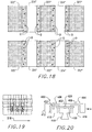
- FIG 16 shows two sub-camera systems 1, 2 (again, no lens systems or other camera components are shown in Figure 16 to avoid unnecessary complexity).
- the sub-camera system 1 is shown, for example, with six detector arrays 322, and the sub-camera system 2 is shown, for example with four detector arrays 324.
- each detector array is considered to be, for example a 2,000 x 3,000 array.
- the lens are, for example, 100 mm focal length, and the distance between the lens is, for example 200 mm.
- Separate respective sensor electronics modules capture and store data each respective detector array.
- a respective mechanical shutter operates for each respective lens system. Integration and synchronization of all these sub-systems has to be accomplished. Overlap in flight paths is used of acquiring redundant data in marginal edge portions of adjacent macro-images, if it is desired to piece together multiple macro-images.
- the data flow to produce a seamless image is organized in three phases as follows.
- a laboratory calibration will be performed for each camera before any production images are made.
- the calibration assesses the optical properties of the camera parts by imaging a known test field in a laboratory environment. This defines where the sub images of a particular optical system go in the stitched final image.
- the steps used are as follow:
- Phase B Image acquisition in a moving platform
- the camera will be mounted in an airplane and images will be produced by each cone, and within each cone, with each square array (image patch or sub-image). These sub-images will be stored in a digital mass storage medium for subsequent processing.
- each cone will be released or actuated sequentially at carefully timed intervals related to speed of flight, so that the optical center 325, 326 of each cone 1,2 is at the same location along the flight path when the image is taken. That means that if two cones are a distance of 30 centimeters apart in the direction of flight, their shutters will be released one after the other so that the airplane has flown 30 centimeters. At a speed of 70 meters per second, this would, in this example, be an interval of 4.3 milliseconds. In this manner, the geometric differences between the sub images of the two cones would be minimized and the sub-images all have the same optical center.
- the sub-cameras 1, 2 both have to be oriented and focused in such a manner that their respective optical axis intersect the large area object being imaged at the same center point (e.g., point on the ground) at the same time.
- Phase C Converting the sub-images into a large seamless "stitched "frame image
- a stitched output image is being produced from the many sub-images stored in the storage medium.
- the total number of sub-images is k1 + l2 + ...kn, if there are n optical sub-systems (cones), and in each cone i exist ki imaging arrays.
- Figure 17 illustrates the basic idea of the data stitching operation. Steps are as follows:
- One of the cones 9e.g., cone 1) is called the "master cone” of the camera. Its sub-images 322" will be placed into the proper locations of the output image using the calibration information from Phase A sub-images 324" from the other n-1 cones are then used to fill in the empty spaces left by the sub-images 322" from the master cone 1. to fill in those spaces, the sub-images 324" of those secondary cones(s) 2 (or n-1) are being matched geometrically and radiometrically with the sub-images 322" of the master cone 1. If any discrepancies are detected, then they are being removed by geometrically resampling the secondary sub-images 324" to geometrically fit with the sub-images 322" of the master or primary cone 1. Analogously, the gray values are adjusted to fit the secondary sub-images 324" into their gray values of the sub images 322" of the master cone 1.
- tie points such as Q 1 , Q 1 ', Q 2 , Q 2 ', Q 3 , Q 3 ', Q 4 , Q 4 ', Q 5 , Q 5 ', Q 6 , Q 6 ' of Figures 3a-e .
- Each sub-image 324" of cone 2 is transformed into the system of cone 1 to a sub-pixel accuracy, while the fit was not sub-pixel accurate before (e.g. 4 pixels at image scale of 1/5000, speed of 70 m/sec and 3 msec delays.
- the raw image data After the process of image data acquisition, the raw image data get post-processed and converted into the large format, seamless, color frame images by exploiting the computing owner of the one or multiple digital data processors of the intelligent image "box".
- the large seamless color frame images are stored on the one or more mass data storage media of the intelligent image "box".
- the mode on board a vehicle e.g. an aircraft
- a vehicle e.g. an aircraft
- the sub-images will be taken when the camera has moved only 35 meters. Since the camera will cover perhaps a 90-degree field-of-view, thus 500 meters from a flight altitude of 500 meters, images will be overlapping greatly.
- This redundancy can be used to fill in holes in the final image (see Figure 19 ), and it can be used to reduce the number of sub-camera systems needed, as compared to still camera applications.
- the field-of-view is defined by the optical lens of the camera.
- additional optical systems cones
- detector array or use more array detector arrays in one single cone.
- the large format digital camera systems of this invention can be equipped with a passive platform assembly 400, as shown in Figure 20 , to minimize vibrations and to minimize movements caused by the carrier 402 of the camera 410, which may degrade the quality of the images acquired by the camera 410 (motion blur).
- the camera carrier 402 of the passive platform assembly 400 is equipped with small scale acceleration sensors 404, which are mounted on the camera carrier 402 in such a way that residual vibrations and movements of the camera 410 are detected over a short period of time.
- the signals of the small scale acceleration sensors 404 are transmitted to the camera control system (not shown in Figure 20 ) and evaluated in such a way that a decision can be made whether a serious degration of the image quality (motion blur) caused by such residual vibrations or movements is expected or is not expected.
- the camera 410 is designed in such a say that multiple exposure of detector arrays are possible within an extremely short period of time.
- the digital sub-images acquired by these multiple exposure will not be stored unless the evaluation of the signal of the small scale acceleration sensors 404 show no serious vibrations or movements of the camera carrier 402.
- the series of multiple exposures is repeated until the evaluation of the signal of the small scale acceleration sensors 404 show that a sub-image is being acquired without quality degration due to vibrations or movements (motion blur).
- Such non-degraded sub-images i.e., the last of the series, is exposed within an extremely short period of time and is stored on digital media or memory during a much longer time.
- the camera carrier 402 of the platform assembly 400 has outer swingers or outriggers 406, 408 with camera 410 looking down and two masses 412, 414 connected rigidly to the respective outriggers 406, 408.
- Two inner masses 416, 418 are hung on an inner swinger bar 420, which is connected pivotally 422 to the camera carrier 402.
- a damper 424 is connected between at least outrigger 406 and at least one of the inner masses 416, 418 or to the inner swinger bar 410 to dampen any vibrations or relative movements between the camera carrier 402 and the inner masses 416, 418. residual vibrations or relative movements in the 404 as explained above.
Landscapes
- Engineering & Computer Science (AREA)
- Physics & Mathematics (AREA)
- General Physics & Mathematics (AREA)
- Multimedia (AREA)
- Radar, Positioning & Navigation (AREA)
- Remote Sensing (AREA)
- Theoretical Computer Science (AREA)
- Studio Devices (AREA)
- Cameras In General (AREA)
Description
- This is a nonprovisional patent application based on the provisional
patent application number 60/289,008 - This invention is related generally to photogrammetry and more specifically to large format digital cameras for acquiring images of large area objects or large areas of large objects, such as aerial images of portions of the surface of the earth.
- It is often desirable to photograph or otherwise acquire digital images of large areas of objects, but in large formats to enhance detail resolution for visual inspection or analysis. For example, it is easy to get a picture of a mountain with a digital camera by backing far enough away from the mountain until the entire mountain fits within the field of view of camera lens, set the focus at infinity, and push the button on the camera to take the picture. The resulting picture of the mountain, which, when processed and printed, can be held in a person's hand and pasted onto a page in a scrap book, may appear to be sharp and clear, but it may not be possible to discern an individual house built on the side of the mountain in the picture because the house is too small. Expanding or "blowing up" the picture to a larger size might make it possible to discern the house, but it may still be impossible to see the doors, windows, roof lines, and other details of the house because the resolution of such fine details just might not be in the picture.
- If the camera could have a larger field of view, such as a wider angle lens, so that it would not have to be backed so far away from the mountain to fit the view of the mountain within the field of view of the lens, some enhancement of details, i.e., higher resolution, could be obtained. Such wide angle lenses, sometimes called "fisheye" lenses, are well-known, but they also distort the image---magnifying portions in the middle and diminishing marginal portions of the image.
- Resolution obtainable by digital cameras is also limited by the sizes of photodetector arrays. Images are detected in digital cameras by focusing light on an image onto an array of photodetector devices, such as charge-coupled devices (CCD's). Each photodetector in the array produces an electric signal, the voltage or current of which is a function of the intensity of all the light that is focused onto that photodetector. Thus, if all of the light reflected by the house in the above-described mountain scene is focused onto one photodetector, the electric signal (voltage or current) level produced by that photodetector will be indicative of the average light energy reflected from the entire house. Therefore, such signal output might enable one to discern that there is something in the resulting mountain picture where the house is located, but it would not be able to produce a recognizable house shape, much less details of doors, windows, roof lines, and the like. Furthermore, no amount of enlargement or "blowing up" of the picture could produce more detail. It would just produce a larger spot in a larger image of the mountain scene, because the resolution is limited to a single electric signal for the entire house.
- On the other hand, if the light reflected from the house could be focused on an array of tens or even hundreds or thousands of individual photodetectors, so that light reflected from a window, for example, is focused on one or more individual photodetectors, while light reflected from doors, walls, and different roof sections of the house could be focused on other respective multitudes of individual photodetectors, then individual electric signals indicative of light energies reflected from each of those various parts or features of the house would be available for producing more details of the house in the image, i.e., there would be higher resolution in the picture.
- These same principles apply to aerial and other types of digital photography. For example, if in taking an aerial picture of a city, all of the light reflected from a city block is focused on one photodetector, it may be possible to discern the block in the resulting picture, but it would not be possible to discern individual buildings, back yards, alleys, cars in driveways, and the like. However, focusing the light reflected from the city block onto an array of hundreds or even thousands of photodetectors would enable resolution capable of discerning such details in the city block.
- A problem faced by digital camera manufacturers is that large photodetector arrays, to the extent they are commercially available, are not inexpensive. Therefore, most camera designers and manufacturers are limited to commonly available photodetector arrays. Rectangular array sizes of about 1,000 x 1,000, i.e., about 1,000,000, photodetectors are now fairly common and readily available, while arrays of 5,000 x 5,000, i.e., about 25,000,000 photodetectors, or more are considered to be "large" and expensive. These array sizes are impressive compared to only a few years ago, and sizes of photodetector arrays will no doubt continue to grow in coming years. They are, none the less, still limited. Several high-end camera manufacturers do make digital cameras with 10,000 x 10,000 arrays, i.e., about 100,000,000 photodetectors, but the costs of such cameras are prohibitive fore most purposes. Therefore, most aerial photographers have to choose between setting their digital camera equipment to obtain pictures or images of large areas, such as entire cities or more, with low resolution (i.e., ability to discern few details), or to obtain smaller area pictures or images, such as parts of cities, but with higher resolution.
- Besides cost, there are other limitations of such "large" array digital camera, especially as compared to analog cameras using film, which can generally achieve better resolution than conventional digital cameras. For example, radiometric performance, i.e., gray scale and/or color resolution of analog film cameras generally not as good as that of digital cameras. On the other hand, large arrays of photodetectors often have defective detector elements that produce defective images. Also, their large size, and, especially the time it takes to read an image of a large array of photodetectors, are all significant problems. The read-out time alone can reduce their usefulness to situations in which there is no movement in the object of between the object and the camera, because such movement before all the electric signals from all the photodetectors in the array that can be read could introduce distortions in the resulting picture or image. Further, such large detector for large format photogrammetry applications have to be nearly flawless, i.e., few, if any, bad photodetectors, because there is no redundancy and bad photodetectors in the array will leave flaws in images being acquired by the detector array. The requirement for such flawlessness puts further pressure on cost of such cameras.
- Other methods to overcome these limitations for acquiring larger format images of large area objects, such as macro- and micro-scanning cameras, also take time to create the image. Scanning cameras are ones in which a linear array of photodetectors are moved in the stationary image plane of a camera to cover the entire image format or view. A similar effect, but different method, is to move (rotate) the camera, usually in an arc about an axis that extends through the lens and is parallel to the scene or object and to the image plane. Cameras that use this latter technique of scanning the object by rotating the camera are called panoramic cameras. Both scanning cameras and panoramic cameras, as described above, also require that the object does not move in relation to the location of the camera, and vice versa, while the object is being scanned to collect the image.
- Satellite imaging of the earth's surface or of surfaces of other planets, moons, and the like, has long come to rely on kinematic imaging with a scanning linear detector array, which has come to be known as "push-broom" scanning. In such "push-broom" scanning, the entire camera, including both the lens and the linear array of photodetectors, is mounted on the satellite and moves with the satellite in relation to the object, which is the earth's (or other planet or moon) surface. The image of the object (earth or other planet or moon surface), therefore, is collected in individual linear paths corresponding to the linear array of photodetectors being swept over the object, and a plurality of such paths are then assembled together to produce the image. In such "push-broom" scanning, the object (earth, etc.) must not "move" as it is being scanned, i.e., the satellite with the camera remains a fixed distance from the center of mass of the earth during the satellite's movement and scan of the earth's surface. The problem with such "push-broom" scanning is that it is difficult to know the camera path accurately, which results in a notorious lack of accuracy in stereo measurements or mensuration in the resulting images.
- A recent aerial camera system developed by LH Systems, of Englewood, Colorado, USA, which is similar to a 1969 doctoral dissertation of E. Derenyi and based on a system previously developed by the German Aerospace Establishment DLR for use on a Mars mission, uses multiple linear detector arrays, instead of film, in the image plane of a conventional high quality lens system to match or exceed performance of analog film-based cameras in aerial photogrammetric applications. As the aircraft or spacecraft flies over the object, each detector array produces a "push-broom" strip of imagery, but these "push-broom" strips are not geometrically independent, since the multiple image lines are collected simultaneously with the same camera. A point on the ground in the path of the multiple "push-broom" image acquisitions is imaged as many times as there are linear arrays in the camera. A problem is that each image line has a separate perspective center, so the resulting composite image of the object has many perspective centers.
- A variation of this multiple linear array approach is shown in the Patent Cooperation Treaty (PCT) patent application no.
PCT/DE00/01163 (International No.WO 00/66976) filed by W. Teuchert and W. Mayr - Another approach to aerial imaging was announced recently by ZI, Inc., a subsidiary of Zeiss-Germany and Intergraph-USA, combines several cameras that take images simultaneously. Four cameras, i.e., four separate lens and sensor assemblies, mounted together produce four separate sub-images of the parts of the object that are in the respective fields of view of the four cameras. Each sub-image has its own perspective center, with each of the four optical centers being in the middle of its respective sub-image. A large-image format can be assembled from the sub-images, but accuracy can suffer because of differences among the multiple cameras, and it has the problem of multiple perspective centers---one for each camera.
-
US 5,864,133 discloses a cost-effective optical device used for converting a photo-image into electronic signals with high resolution. The optical device includes a plurality of focusing units for receiving a plurality of sections of the photo-image respectively, and generating a plurality of corresponding focused image sections wherein the focusing units are mounted in specific locations for focusing the plurality of sections of the photo-image through various light paths and at various distance, and the plurality of corresponding focused image sections are magnified with the same ratio, a photoelectric conversion unit for sequentially converting the plurality of corresponding focused image sections into the electronic signals, and a light-reflecting unit mounted between the plurality of focusing units and the photoelectric conversion unit for sequentially transmitting the plurality of corresponding focused image sections to the photoelectric conversion unit. -
US 4 383 170 A discloses a method of acquiring a large area image by acquiring a plurality of small area images that are acquired by sequentially focusing multiple non-overlapping portions of the large area through a compound lens system onto a photosensitive array. - It is the object of the present invention to provide an improved method and system for acquiring a large area image of a large area object.
- The object is solved by the subject matter of the independent claims. Preferred embodiments of the present invention are defined by the dependent claims.
- Accordingly, a general object of this invention is to provide a method and camera apparatus that can produce high resolution, large format, digital images of large area objects.
- A more specific object of the present invention is to provide a large format, digital camera system and method for acquiring large format, digital images of large area objects, but without the requirement and costs of large, expensive, detector arrays.
- Another object of the present invention is to provide a large format, digital camera system and method for acquiring large format, digital images of objects that are either moving or stationary.
- Another specific object of the present invention is to provide a method and camera apparatus for acquiring instantaneous, large format, digital images of an object so that movement of the object or of the camera apparatus does not cause blurring or distortion of the images.
- Still another object of the present invention is to provide a method and camera apparatus for acquiring large format, digital images of a large area object inexpensively enough that there can be a degree of redundancy in order to produce high quality, large format, digital images without having to rely on flawless detector arrays.
- Yet another object of the present invention is to provide a method and camera apparatus for acquiring large format, digital images of large area objects with fast and efficient digital data read-out and processing.
- A further object of the present invention is to provide a method and camera apparatus with high resolution, wide angle geometry for a wide field of view and for good stereo digital imaging.
- A still further object of the present invention is to provide a method and digital camera' apparatus for producing a large image format that has a single perspective center.
- Additional objects, advantages, and novel features of the invention are set forth in part in the description that follows and will become apparent to those skilled in the art upon examination of the following description and figures or may be learned by practicing the invention. Further, the objects and the advantages of the invention may be realized and attained by means of the instrumentalities and in combinations particularly pointed out in the appended claims.
- To achieve the foregoing and other objects and in accordance with the purposes of the present invention, as embodied and broadly described herein, a method of this invention may comprise digital camera systems in which two-dimensional arrays are exposed to multiple portions or sub-areas of large area objects to acquire overlapping sub-images of such sub-areas. The digital sub-images can then be pieced or stitched together in a digital mosaic to form a digital macro-image of the large area object. According to the invention, the sub-images can be acquired by a single, two-dimensional, detector array and exposed sequentially to the different sub-areas by different lens systems. In non-claimed examples, clusters comprising multiple, spaced apart, two-dimensional detector arrays are exposed to different sub-areas of the large area object by a single lens system either sequentially or simultaneously to acquire the overlapping sub-images.
- In a preferred embodiment, a large format, digital camera system comprises more than one sub-camera system, and each sub-camera system has its own lens system with at least one detector array in the focal plane of each lens system. The lens systems have the same focal length and are mounted closely together in a manner that makes their focal planes coplanar and their optical exes parallel to each other. The detector array(s) of the different sub-cameras are exposed by the respective single lens systems of the sub-cameras to overlapping sub-areas of large area objects so that sub-images acquired by different sub-cameras have overlapping areas to facilitate piecing or stitching them together into a seamless macro-image of the large area object. If the large format, digital camera system moves in relation to the large area object, the shutters and image acquisition systems of the respective sub-cameras can be actuated in timed sequence coordinated with the speed of movement to make the perspective centers of the sub-camera images match the perspective centers of the other sub-camera images. Therefore, when the macro-image is pieced or stitched together from the sub-images, it has a single perspective center. If it does not move, the shutters and image acquisition systems can be actuated either sequentially or simultaneously, but the macro-image will have a plurality of perspective centers, i.e., one perspective center for the images acquired by each sub-camera system. Thus, a large format, digital camera comprising four sub-camera systems will, if not moving with shutters actuating in the timed sequence, have four perspective centers.
- More detector arrays can be added to each sub-camera system to increase the format size of the large format, digital camera system, or the detector arrays can be larger to increase the format size without adding more sub-cameras. Of course, adding more sub-cameras can also increase format size.
- Repeat image acquisition of the same object through different color filters to provide overlapping color sub-images can add color to the macro-image. Alternatively, addition of another sub-camera system with overlapping color detector arrays or near infrared arrays can add color or near infrared imaging capabilities. The color and/or near infrared arrays can be two-dimensional or, if the camera moves, linear and can, but does not have to, be less resolution than the monochromatic or panchromatic sub-image arrays, thus can have different focal lengths. The lower resolution color overlay is registered to the higher resolution monochromatic or panchromatic macro-image, and the high resolution monochromatic or panchromatic macro-image content is used to segment and enhance the quality of the color overlay.
- The sub-image read-out from the various detector arrays is accomplished simultaneously in a parallel manner for speed. Digital correlated double sampling is used to convert the individual photodetector output signals twice per pixel using an analog to digital converter at the double sampling rate and to perform the subtraction of the residual reset signal to the actual light exposed signal in the digital domain. An accelerometer on a dampened camera carrier platform outputs signals during sub-image acquisition, which are used to evaluate vibration or movement magnitude. Sub-images are rejected and the shutter is re-actuated to re-acquire images in short order when the magnitude of vibrations or movement is large enough to degrade the sub-image quality.
- The accompanying drawings, which are incorporated in and form a part of the specification, illustrate the preferred embodiments of the present invention, and together with the descriptions serve to explain the principles of the invention.
-
-
Figure 1 is a perspective, diagrammatic, view of a digital camera with a single detector array and multiple lenses acquiring a large format image of a large area object according to this invention, such as, for example, an image of a geographical area of the earth with the digital camera mounted on a helicopter; -
Figures 2a-d illustrate a plurality of sub-images of overlapping sub-portions of the large area object acquired by the digital camera ofFigure 1 ; -
Figures 3a-f illustrate the process of stitching the sub-images ofFigures 2a-d together into a large format macro-image; -
Figure 4 is a perspective view of a large format, digital camera of a non-claimed example with a single lens system and multiple detector arrays in the focal plane; -
Figure 5 is a view of overlapping sub-images produced by shifting the optical path of the camera system ofFigure 4 ; -
Figure 6 is an isometric view of a non-claimed example of a large format digital camera system comprising a plurality of sub-camera systems, each having one or more detector arrays exposed by a lens system; -
Figure 7 is a view of overlapping digital sub-images produced by the digital camera system ofFigure 6 to form a composite, large format macro-image; -
Figure 8 is a view similar toFigure 7 , but with a different example number and pattern of sub-images; -
Figure 9 is a view similar toFigure 7 , but with yet another different example number and pattern of sub-images; -
Figure 10 is a diagrammatic view of the detector arrays of a large format, color, digital camera system; -
Figure 11 is a diagrammatic view of the monochromatic or panchromatic, large format, macro-image formed by combining sub-images acquired from sub-camera systems of the large format, color digital camera system ofFigure 10 ; -
Figures 12a-c are blue, red, and green sub-images acquired from blue, red, and green detector arrays of the camera system ofFigure 10 ; -
Figure 13 is a near infrared sub-image acquired from the near infrared detector array of the camera system offigure 10 ; -
Figure 14 is a function block diagram of the digital processing of photodetector signals of the large format, digital cameras; -
Figure 15 is a diagrammatic view of another embodiment large format, color, digital camera system; -
Figure 16 is a diagrammatic view of example detector arrays of a large format, digital camera system of this invention to facilitate describing the signal processing and stitching of acquired sub-images into large format, macro-images according to this invention; -
Figure 17 illustrates one phase of the signal processing and stitching process of this invention; -
Figure 18 illustrates another phase of the signal processing and stitching process of this invention; -
Figure 19 illustrates a large format, macro-image comprising overlapping sub-images according to this invention; and -
Figure 20 illustrates a dampened camera platform apparatus with accelerometer read-outs of residual vibration and movement for use in determining whether sub-images obtained by sub-camera systems of this invention are too degraded by vibrations and/or movement for use in making a large format, macro-image. - One of the simpler, yet effective, large format, digital camera systems of this invention is illustrated diagrammatically in
Figure 1 . Essentially, the largearea camera system 10 infigure 1 is represented by a plurality oflens systems photodetector array 20 positioned in the focal plane of thelens systems photodetector array 20 is connected electrically bysuitable conductors 22 to acontrol circuit 24, which includes at least a microprocessor, input/output circuitry, memory, and power supply for driving thephotodetector array 20, reading sub-image data out of thephotodetector array 20, and storing such sub-image data. Other data processing functions, such as combining sub-images and/or image display functions, can be accomplished in thecamera system 20 or with other peripheral data processing equipment. - The large
format camera system 10 inFigure 1 is illustrated simplistically in the process of acquiring a large format digital image (not shown inFigure 1 ) of alarge area 20 of anobject 32, for example, a semi-developed geographical area on the earth's surface that includes astream 34,railroad 36, three buildingstructures cross streets bridge 48, where oncross street 46 crosses thestream 34. Of course, the components of thecamera system 10, andlarge area 30 of theobject 32 are not shown in actual sizes, proportions, or details, which would not be practical or even possible within the constraints of the drawing format, as would be understood by persons skilled in the art. Also, details ofappropriate lens systems detector array 20, andcircuits - Referring, now to
Figure 1 in combination withFigures 2a-d , thecamera system 10 is shown with fourlens systems sub-areas large area 30 onto thedetector array 20. However, any plurality of lens systems would work for purposes of this invention. - In
Figure 1 , thefirst lens system 12 focuses afirst sub-area 50 onto thedetector array 20, and then thesecond lens system 14 focuses asecond sub-area 52 onto thedetector array 20, thethird lens system 16 focuses athird sub-area 54 onto thedetector array 20, and thefourth lens system 18 focuses afourth sub-area 56 onto thedetector array 20, all in sequential order. Thelens systems marginal edge area 60 is common to sub-areas 50, 52. Likewise, overlappingmarginal edge area 62 is common to sub-areas 50, 54,marginal edge area 64 is common to sub-areas 52, 56, andmarginal edge area 66 is common to sub-areas 54, 56. - Each
lens system detector array 20 can be exposed to only one of the sub-areas 50, 52, 54, 56 at a time. The shutters and their actuators are not shown inFigure 1 because of drawing size constraints, but shutters and shutter actuators are well-known to persons skilled in the art, who would be able to implement them without difficulty to practice this invention. Therefore, there is no need to describe shutters in lens systems or their actuators for purposes of describing this invention. Suffice it to say that such shutter actuators are connected to thecontrol circuit 24 by suitable electric leads orconductors 26 so that read-out of image data from thedetector array 20 can be coordinated with actuation of the respective shutters inlens systems - As the shutter in the first lens system is opened to expose the
detector array 20, thecontrol circuit 24 reads out the sub-image 70 (Figure 2a ) ofsub-area 50 from thedetector array 20. As is understood by persons skilled in the art, thedetector array 20 comprises an array of individual photodetectors, e.g., semiconductor devices that output an electric signal, the magnitude of which is dependent on the intensity of light energy incident on such photodetector. Therefore, the signal from each photodetector in thearray 20 is indicative of light energy intensity from a pixel area of the sub-area 50, and the signals from all of the individual photodetectors in the array are indicative of light energy intensity from all of the pixel areas of the sub-area 50. Therefore, the signals from the photodetectors in thedetector array 20, together, are indicative of the pattern of light energy from the sub-area 50, so a sub-image 70 (Figure 2 ) of the sub-area 50 can be produced from such signals. First, however, the signals are amplified, digitized, processed, and stored, as is well-known to persons skilled in the art. - After exposing the
detector array 20 to thefirst sub-area 50 to acquire the sub-image 70 in digital form, as described above, the shutter for thesecond lens system 14 is actuated to acquire and store a sub-image 72 (Figure 2b ) of the sub-area 52 in digital form. Acquisitions of sub-image 74 (Figure 2c ) ofsub-area 54 and of sub-image 76 (Figure 2d ) ofsub-area 56 bylens system 16 andlens system 18, respectively, are accomplished in a similar manner. The read-out time for a detector array less than 5,000 x 5,000 is typically less than one second, such as about one-half a second. - When all of the overlapping
sub-images Figures 3a-f to produce a large format, macro-image 80 (Figure 3f ) of thelarge area 30 of object 32 (sometimes referred to as the large area object 30). Such piecing together procedure is preferably performed in the digital format of the sub-images 70, 72, 74, 76 by software, similar to the procedure for stitching together adjacent digital images with overlapping marginal edge portions described inU.S. Patent No. 6,122,078 and/or in co-pendingU.S. Patent application, serial no. 09/187,254 . The preferred method is to use known or calculated mechanical measurements or relationships to piece therespective sub-images marginal edge areas - As illustrated in
Figure 3a , one of the sub-images, forexample sub-image 70, is chosen as the master sub-image, and its pixel array is chosen as the master X-Y coordinatesystem 82. For piecing the second sub-image 72 together with the first, or master, sub-image 70, it is first joined as closely as possible with known or measured mechanical dimensions and relationships based on relative positions and orientations of therespective lens systems 12, 14 (Figure 1 ), size of thedetector array 20, distances of thelens systems detector array 20 from thelens systems common features marginal edge portion 60. Theoretically, the master coordinates of pixels ofdistinct features same features 38', 40', 44' in thesecond sub-image 72, both of thesesub-images Figure 1 ). However, the parallaxes due to the different locations of therespective lens systems Figure 3a . - To perfect the synthesis or 'stitching" together of the first and second sub-images 70, 72, the software can identify distinct features in the overlapping
marginal edge portion 60 of bothsub-images respective sub-images first sub-image 50. Application of ordinary geometry and trigonometry can then be used to shift, including rotating, if necessary, the entire local coordinatesystem 84 of thesecond sub-image 72 and thereby adjust the coordinates of all the pixels in the second sub-image 72 to maintain their individual spatial relationships with the adjusted points Q1' and Q2'. Thus, by identifying several distinct points Q1, Q1' and Q2, Q2' in the first and second sub-images 70, 72 and adjusting the coordinates of the points Q1' and Q2' to register them together in the overlappingmarginal edge area 60 and then adjusting the coordinates of all the rest of the pixels in the second sub-image 72 to maintain their spatial relationships with the points Q1' and Q2', the two sub-images 70, 72 are stitched together geometrically to form thetop half 86 of the large format, macro-image, as shown in Figure 36. Of course, if there are no identifiable distinct features in adjacent sub-images, such as if they showed only continuous sea or sky, then the distinct feature-base stitching described above is not needed, and the initial placement by the coordinate systems based on the relative positions and orientations of the lens systems, etc., is sufficient. - The remaining two
sub-images image 86 does not look darker or brighter than the other part. Such gray scale variations in thiscamera system 10 are usually not a significant problem, because all thedigital sub-images Figure 1 ). However, it does take some time to read out all of the sub-images 70, 72, 74,76 sequentially from the detector array 20 (e.g., about two seconds for a 2,000 x 2,000 detector array). Therefore changes in light energy reflected from theobject area 30 due to clouds floating over or other lighting changes is possible while the sub-images 70, 72, 74, 76 are being read out. Also, there is some signal output drift, i.e., different electrical signal output for the same incident light energy, in many detector arrays. Therefore, some radiometric adjustment may be necessary, even though all of the sub-images 70, 72, 74, 76 are read out of thesame detector array 20 in thecamera system 10 described above. Such radiometric adjustments can be made with software by comparing output signal intensity of at least one, but preferably more, pixels of the first sub-image 70 with matching pixels of the second sub-image 72 in the overlappingmarginal edge area 60. Whatever adjustments of signal intensity is needed to make the compared pixels in the second sub-image 72 match or nearly match the corresponding pixels in the first sub-image 70 can then be applied also to the other pixels in the second sub-image. - As illustrated in
figure 3c , the third sub-image is also brought into the master X-Y coordinatesystem 82 based on mechanical relationships and/or measurements. Then, distinct, corresponding features or points, e.g., Q3, Q3' and Q4, Q4', of the upper half-image 86 and the third sub-image 74 are identified in the overlappingmarginal edge area 62. Adjustments are made, as described above, to stitch the third sub-image 74 together with the upper half-image 86 to produce the three-fourth-image 88, shown inFigure 3d . Radiometric adjustments can also be made, as explained above. - Finally, as illustrated in
Figure 3c , the fourth sub-image is also brought into the master X-Y coordinatesystem 82 based on mechanical relationships and/or measurements. The distinct, corresponding features or points, e.g., Q5, Q5' and Q6, Q6', of the three-fourths-image 88 and the fourth sub-image 76 are identified in either one or both of the overlappingmarginal edge areas image 88 to produce the full, large format, macro-image 80, shown inFigure 3f . This large format, macro-image 80 is, of course, the large image of thelarge area object 30 inFigure 1 . Radiometric adjustments can also be made, as explained above. Also, if perfect registration of the points Q5, Q5' and Q6 Q6' or other identified points in overlappingmarginal edge areas - The
large format image 80 of thelarge area object 30 can be acquired as described above with a readily available, normal-size detector array 20, such as a 1,000 x 1,000 array or a 2,000 x 2,000 array, instead of a very expensive, large detector array, yet the resolution is four times better than would be attainable with a conventional digital camera with such a normal-size detector array. Of course, as mentioned above, thedigital camera system 10 could be equipped with more lens systems to create even more sub-images and thereby make even a larger format camera for even better resolution. - While reading out, processing, and stitching together four, or even more, sequential sub-images with the large format,
digital camera system 10 described above is quicker, more efficient, and takes less computer capacity than comparable-sized digital cameras with large detector arrays, the time required for such sequential read-outs of sub-image data from asingle detector array 20 can be a detriment and requires that the object remain still and not move in relation to thecamera system 10 during such sub-image data acquisition. While there are many applications for this kind of large format,digital camera 10, such as for acquiring digital images of paintings, landscapes, or even aerial shots (if the platform is still, such as from a helicopter or hot-air balloon, this drawback is solved by a non-claimed example of a largeformat camera system 100, shown diagrammatically inFigure 4 , which acquires multiple sub-images simultaneously. - As shown in
Figure 4 , asingle lens system 102 is used to focus a large area object (not shown inFigure 4 , but similar to the large area object inFigure 1 ) onto a plurality of detector arrays, for example, the ninedetector arrays focal plane 122 of thelens system 102. Each of the detector arrays can be a normal size, such as 1,000 x 1,000 or 2,000 x 2,000, but such nine normal-size detector arrays detector arrays - While such large
format camera system 100 has the advantage of exposing a plurality ofdetector arrays physical gaps focal plane 122. Such gaps cannot be avoided, because the sensitive area of eachdetector array - There are several approaches to filling the gaps between the sub-images produced by the plurality of
detector arrays more cameras 100 together into one system to produce overlapping sub-images. Another approach is to rotate a prism (not shown) in theoptical path 132 to shift the projection of the light onto the set ofdetector arrays Figure 5 . A rotation of the prism (not shown) at 90, 135, and 180 degrees would cause shifts to the left, down, and left + down, respectively. Eachdetector array Figure 5 . For both approaches of filling the gaps between the initial set of sub-images, as described above, software is used to stitch together the overlapping sub-images by identifying distinctive features or points in overlapping sub-image areas and then adjusting pixel coordinates to register the distinctive features or points in a manner similar to that described above forcamera system 10. - The former approach to filling the gaps between adjacent detector arrays in a camera system comprising multiple detector arrays exposed to the large area object through a single lens system, as described above, can be enhanced to an improved large
format camera system 150, as illustrated inFigure 6 , wherein the detector arrays exposed through a single lens are spread farther apart than in thecamera system 100 ofFigure 4 , and the fill is provided by a plurality of additional cameras. As shown inFigure 6 , this largeformat camera system 150 comprises a plurality, e.g., four, connected sub-camera systems designated as 1, 2, 3, and 4. Eachsub-camera system macro-camera system 150 is, itself, a large format camera system similar to the largeformat camera system 100 inFigure 4 , i.e., each has a plurality of detector arrays exposed to thelarge area object 230. With continuing reference toFigure 6 , the firstsub-camera system 1 comprises a plurality (e.g., six) ofdetector arrays 152 positioned spaced apart from each other in thefocal pane 154 of thelens system 156. Thespaces 158 between thedetector arrays 152 are preferably almost, but not quite, as long or as wide as adetector arrays 152, so that sub-images from other ones of thesub-camera systems detector arrays 152 with some overlap in the marginal edge portions for stitching together to make a large area macro-image in a manner similar to that described above forcamera system 10 and as will be explained in more detail below for thiscamera system 150. When all six of thedetector arrays 152 ofsub-camera 1 are exposed to thelarge area object 230 bylens system 156, each of the six detector arrays will create a sub-image of a part or sub-area 1' of thelarge area object 230 with some overlap at marginal edge portions into adjacent sub-areas, as explained above. Those sub-images acquired by thesub-camera system 1 are designated 1" in the macro-image 232 inFigure 7 . The large format, macro-image 230" inFigure 7 is a macro-image of thelarge area object 230 inFigure 6 pieced or stitched together from thesub-images 1", 2", 3", 4" acquired by all thesub-camera systems large area object 230 is theperspective center 155 of thesub-camera system 1, i.e., on theoptic axis 151 of thesub-camera system 1, it is not included in any of thesub-images 1" inFigure 7 acquired by thesub-camera system 1 ofFigure 6 , because theoptic axis 151 extends through thefocal plane 154 in aspace 158 between thedetector arrays 152 ofsub-camera system 1. - As shown in
Figure 6 , the othersub-camera systems respective lens systems lens system 156 ofsub-camera system 1. The lens systems are mounted adjacent each other, preferably in a common plane, so that theoptic axis lens system Figure 6 of depicting the foursub-camera systems large area object 230, which is very much larger than the camera system 150 (a few millimeters or centimeters between lens systems and object size in meters or even kilometers), make it impossible to draw the lines depictingoptic axes Figure 6 as parallel and still depict other details of the system, but persons skilled in the art can understand and make this mental adjustment in relation toFigure 6 .. Also, eachsub-camera system more detector arrays focal plane lens systems Figure 6 ,sub-camera system 2 has fourdetector arrays 162,sub-camera system 3 has threedetector arrays 172, andsub-camera system 4 has twodetector arrays 182, all positioned so that sub-images acquired by them fill gaps between sub-images acquired bysub-camera system 1 and by other sub-camera systems with some overlap in marginal edge portions to accommodate stitching sub-images together, as described above. One of the advantages of the large format, digital camera system of this example, including, but not limited to thecamera system 150 inFigure 6 , is that larger format macro-images can be acquired, if desired, by either adding more detector arrays, or using larger detector arrays, or both, without having to add more lens systems. - Again, the
optic axes sub-camera systems camera system 150 is mounted on a moving platform, such as an airplane or spacecraft, the shutters of therespective lens systems lens system optic center respective image plane same center 234 of thelarge area object 230, so that the perspective centers 155, 165, 175, 185 of eachsub-camera system corresponding image center 230" inFigure 7 the same for all the sub-images acquired by all thesub-camera systems optic axis sub-camera system object center 234 as its respective shutter is actuated. Consequently, when the sub-images 1", 2", 3", 4" are acquired in this manner, they will all have thesame perspective center 234" corresponding to theobject center 234 and to the respectiveoptic centers different sub-cameras sub-images 1", 2", 3", 4" are stitched together. Thelens systems common plane 140, and thefocal planes lens systems focal planes Figure 6 , but could instead be positioned at corners of a rectangle, square, or any other pattern, but preferably coplanar and close together to minimize the distance between parallel axes. - The
sub-images 1" of sub-areas 1' acquired bysub-camera system 1 are stitched together, as described above, in a mosaic withsub-images 2", 3", 4" of respective sub-areas 2', 3', 4' acquired bysub-camera systems Figure 7 to complete the large format, macro-image 230" oflarge area image 230 ofFigure 6 . Again, as explained above, an advantage of this kind of large format,digital camera system 150 is that it can create alarge format image 230" with a plurality of common, conventional size, detector arrays and with one commonoptical center 234". Further, this largeformat camera system 150 can accommodate acquisition of all the sub-images with all thedetector arrays perspective center 234 common to all the sub-cameras 1, 2, 3, 4 and to all the sub-images, the resulting macro-image 230" of the largeformat camera system 150 is much like a picture or image acquired with an ordinary film-based camera or an ordinary small format digital camera. - Alternatively, if the
camera system 150 is stationary,, theobject 230 can be either stationary or moving at moderate speeds in relation to thecamera system 150, and the resultinglarge format image 230" will not be distorted any more than would be a picture or image acquired by an ordinary film-based camera or a small format digital camera. For example, the large format,digital camera 150 could be used in a stationary position to make a large format, digital image of a painting or of a landscape scene, or even scenes in which an object is moving at a moderate speed, where the large format is desired for better resolution of details than can be acquired with ordinary size format digital cameras. - In the example large format
digital camera 150 ofFigures 6 and7 , an example size for eachdetector array large format image 230" of about 9,000 x 8,500 pixels. Different numbers and arrangements or patterns of detector arrays in sub-camera systems can be used to produce different sized macro-images. For example, four detector arrays in a first sub-camera system, two detector arrays in a second sub-camera system, two detector arrays in a third sub-camera system, and one detector array in a fourth sub-camera system can produce a mosaic and resultingsmaller macro-image 236" illustrated inFigure 8 . going larger, the macro-image 238" inFigure 9 can be produced by a first sub-camera system with twelve detector arrays, a second sub-camera system with nine detector arrays, a third sub-camera system with eight detector arrays, and a fourth sub-camera system with six detector arrays. Again, theseexample macro-images 236" and 238" ofFigures 8 and9 are produced with a common optical center for all sub-cameras in the system. - For control of sub-image acquisitions, each of the
sub-camera systems digital camera system 150 inFigure 6 preferably has an electronically controlled shutter (not shown) but is well-known to persons skilled in the art in itslens system camera system 150 is mounted on a moving vehicle, such as an aircraft or spacecraft. Also, it is preferred that each of thedetector arrays respective detector arrays camera system 150 from an airplane. Only medium accuracy is needed for the shutter synchronization for simultaneous exposure of thedetector arrays - The method and apparatus of this invention can also facilitate quick acquisition of large format, color digital images. It is conventional for photodetectors, such as charge-coupled devices (CCD's) to be arranged to produce color digital images directly. However, that approach is typically at the expense of geometric resolution. Therefore, there is a trade-off between: (i) creating color directly with a smaller area photodetector (CCD) array; or (ii) using black and white photodetectors (CCD's) along with multiple cones (lens to focal plane optical path) and color (wavelength) filters. The following options are supported by the method and apparatus of this invention:
- (1) Use of color photodetector (CCD) arrays directly on the focal plane of the
optical systems - (2) Using black and white photodetectors (CCD's) and employing multiple cones with color filters, having one produce green sub-images, a second cone produce blue sub-images, and a third cone produce red sub-images, and then combining the green red, and blue sub-images by stitching into a single color image; or
- (3) Using one black and white set of sub-images in the optical arrangement, but exploiting in-flight redundancy (when the large format camera system is mounted a moving vehicle, such as an airplane or spacecraft) to produce color-using filter wheels in front of the cones, wherein one image is taken in green, the next in red, and the third in blue, one after the other, as the platform moves and then obtaining the single color image by stitching the green, red, and blue images together.
- Color information acquisition with a large format
digital camera system 250 illustrated inFigure 10 is similar to the largeformat camera system 150 inFigures 6 - 9 , but is equipped with additional sub-camera systems, including lens and detector arrays, for color and near infrared (nir). As shown inFigure 10 , there are eightsub-camera systems Figure 10 , which is sufficient for purposes of this description, since the lens systems and other elements of the sub-camera systems can readily be understood by reference back to other embodiments and examples described above. - The
sub-camera systems respective detector arrays focal planes Figure 10 ) have the same focal lengths, as described above forcamera system 150 inFigure 6 . The optical orperspective centers sub-camera systems Figure 10 are the same, i.e., are on the optic axes of the respective lens systems (not shown inFigure 10 ) of the respectivesub-camera systems Figure 10 ), as also described above forcamera system 150 inFigure 6 . Therefore, thesub-images 262", 272", 282" of sub-areas of the large area object being imaged (not shown inFigure 10 ) produced by thedetector arrays sub-images 252" of sub-areas of the large area image, fill the gaps between the sub-images 252" to produce the large format, macro-image 240", as shown inFigure 11 . The overlappingsub-images 252", 262", 272", 282" are stitched together, as described above, to produce the large format, macro-image of the large area object with a high resolution. - The blue (b), red ®, green (g), and near infrared (n)
detector arrays color camera system 250, are also exposed to the large area object. Their resultingsub-images 256"m 266", 276", 286" shown inFigures 12a-c and 13 , respectively, are then also combined with the large format, macro-image 24" to produce colored and/or near infrared large format macro-images. The color sub-images can be produced at the same resolution as the black and white (non-color) sub-images 252", 262", 272", 282", if desired. However, such high resolution is usually not necessary for color purposes. Therefore, theexample color sub-images 256", 266", 276", 286" of the large format, color,digital camera system 250 illustrated inFigure 10 are produced with a lower resolution than the black andwhite sub-images 265", 262", 272", 282". To do so, eachcolor detector array white detector arrays Figure 10 ). Therefore,color sub-images 256", 266", 276", 286" are at a lower resolution than the black andwhite sub-images 252", 262", 272", 282". Of course the blue, red, green, and near infrared sub-cameras that produce thecolor sub-images 256", 266", 276", 286" have to be configured differently than the black and white sub-cameras to produce such lower resolution, color, sub-images 256", 266", 276", 286" on the same size detector arrays. For example, the focal lengths of the lens systems for the color sub-cameras could be shorter than the focal lengths of the black and white sub-cameras in order to expose thecolor detector arrays perspective centers sub-image centers 257", 267", 277", 287" are the same as each other and the same as those of the black and white sub-cameras. - With the
color sub-images 256", 266", 276", 286" each being of the entire large area object, each of such color sub-images can be superimposed onto composite, large format, black andwhite image 240" ofFigure 11 by stitching, as described above. With all three of the primary color blue, red, andgreen sub-images 256", 266", 276" superimposed onto, and stitched together with, the black and white macro-image 240", the macro-image 240" can be colored. Essentially, once thecolored sub-images 256", 266", 276" are registered on the black and white macro-image 240", the black and white pixels are assigned the color values of the dominant (strongest or most intense) color pixels in corresponding geometric locations. For a large format, macro-image in near infrared (nir), the nir pixel values are assigned to the black and white pixels at corresponding geometric locations. - The above-described merging of the high-resolution panchromatic or black and white macro-image 240" with the lower resolution color and/or near
infrared sub-images 256", 266", 276", 286" is preferably, but not necessarily, based on exploiting the high resolution image content of the panchromatic or black and white macro-image for an image segmentation based on edge detection in order to avoid lower resolution color mismatch blurring or bleeding across sharp edges or borders of features in the macro-image 240". In other words, software used to detect distinct features for the stitching process of the panchromatic or black and white macro-image 240" can also detect edges of features. For example, referring back momentarily toFigures 1 - 3 , in addition to identifying a few points on distinct features by contrasts or magnitude of intensity value differences between adjacent pixels for stitching purposes, Q1, Q1', Q2, Q2', Q3, Q3', Q4, Q4', Q5, Q5', Q6, Q6', etc., on distinct purposes, as described above, the software can also identify edges of features in the sub-images 70, 72, 74, 76 and in the macro-image 80, such as the edges of thestream 34,railroad 36,buildings streets bridge 48, and the like. Therefore, for purposes of assigning dominant color and/or nir values from lower resolution color sub-images, 256", 266", 276", such as those described above, to a macro-image 80, the break between, for example, dominant color pixels of water in thestream 34 segment of macro-image 80 color pixels of the adjacent land segment ofmacro-image 80 would be based on the pixels in thehigh resolution image 80 that identify the edges of thestream 34 rather than on the lower resolution pixels of color and/or nir sub-images. In other words, if the dominant color is blue for several low resolution pixel distances on one side of thestream 34 edge marked by high resolution pixels, while the dominant color is green for several low resolution pixel distances on the other side of thestream 34 edge marked by the high resolution pixels, then the break between the blue color (stream 34) segment and the green color (adjacent land) segment will be made by assigning blue values to the high resolution pixels on the one side of thestream 34 edge and assigning green values to the high resolution pixels on the other side of thestream 34 edge. - High quality reading and evaluation of photodetector signals, such as signals form charge-coupled devices 9CCD's), often requires at least some preprocessing of the information at the output of the photodetector. To reduce "reset noise, which is a typical characteristic of CCD's, the voltage of the output signal from the CCD is evaluated twice per picture element (pixel). This process is known as "Correlated Double Sampling" (CDS). Known implementations of the CDS take place in the analog domain. A preferred, but not essential, feature of this invention is to convert the CCD output signals twice per pixel using an analog to digital (a/D) converter at the double sampling rate and to perform the substraction of the two sampled output signals in the digital domain, instead of the analog domain. Such digital subtraction can take place in a digital signal processor, which may also be used for other purposes, such as data compression, or in a programmable logic device used to provide signals necessary to control the CCD. As shown in
Figure 14 , the voltage of theoutput signal 300 of the CCD is sampled first at 301, after deleting the charge of the previous exposure, i.e., of the previous pixel information to obtain its reset level. Then, the actual pixel information is shifted to the output gate and, theoutput signal 300 is sampled again at 302. The difference between thereset voltage 301 and the exposedpixel voltage 302 is the voltage value that is indicative of the actual intensity of the light energy incident on the actual pixel position of the CCD during the exposure. - However, rather than making an analog subtraction of these two
voltage levels Figure 14 , theanalog output signal 300 of the CCD is preamplified and conditioned in apreamplifier circuit 304 and converted to digital format in the analog todigital converter 306.such preamplifier 304 and analog todigital converter 306 circuits and devices are well-known in the art. The digital signal processor orprogrammable logic device 308 then performs the subtraction digitally to read out a digital value of the light intensity that is incident on the CCD. To maintain a speed comparable to a conventional analog subtraction of thesignals digital converter 306 has to e used at twice the sampling rate. This process has the advantages of simpler and more reliable hardware circuitry and better accuracy, because systemic errors of the one and only data path are substracted for the final result, which pushes the concept of Correlated Double Sampling (CDS) to its theoretical limits. - An alternative to the large format, color,
digital camera system 250 ofFigure 10 is the large format, color,digital camera system 310 shown inFigure 15 , especially for kinematic (moving) digital imaging systems, e.g., aerial imaging systems in airplanes and the like. The monochromatic, high resolutionsub-camera systems Figures 6 and7 , thus the same component designation numbers are used inFigure 15 for those components and no further explanation of the acquisition of the monochromatic orpanchromatic sub-images 1", 2", 3", 4" and stitching to produce the monochromatic orpanchromatic macro-images 230" is needed. To add color to the large format, macro-image 230", another sub-camera system 5 with a set of color linear detector arrays, e.g., blue 312, red 314, green 316, is positioned adjacent, or intermingled with, the monochromaticsub-camera systems Figure 15 . The lens system for the color sub-camera system 5 is not shown inFigure 15 , because persons skilled in the art know how to focus the large area object 230 (Figure 6 ) onto thelinear color arrays Figure 15 ). Suffice it to say that the full width of the large area object that comprises the macro-image 230" should be detected by the colorlinear arrays camera system 310 moves as indicated by arrow 318 (Figure 15 ) over thelarge area object 230 9Figure 6 ). Again, as explained above in relation to the large format,color camera system 250 ofFigure 10 , the color sub-images acquired by the linearcolor detector arrays sub-images 1", 2", 3", 4" acquired by the monochromatic onpanchromatic detector arrays linear color arrays detector arrays perspective center 315 of the color sub-camera system 5 be the same as the optical andperspective centers sub-camera systems color detector arrays digital camera system 250 ofFigures 10 - 13 . It is also a feature of this invention that another sub-camera system, similar to, or the same as,sub-camera system 310 with one or more linear arrays of monochromatic, panchromatic, or even color photoelectron capabilities can also be used to fill holes, spaces, or imperfections in or between theother sub-images 1", 2", 3", 4". - To explain the data flow, reference is made, for example, to
figure 16 , which shows twosub-camera systems 1, 2 (again, no lens systems or other camera components are shown inFigure 16 to avoid unnecessary complexity). Thesub-camera system 1 is shown, for example, with sixdetector arrays 322, and thesub-camera system 2 is shown, for example with fourdetector arrays 324. each detector array is considered to be, for example a 2,000 x 3,000 array. The lens are, for example, 100 mm focal length, and the distance between the lens is, for example 200 mm. - Separate respective sensor electronics modules capture and store data each respective detector array. A respective mechanical shutter operates for each respective lens system. Integration and synchronization of all these sub-systems has to be accomplished. Overlap in flight paths is used of acquiring redundant data in marginal edge portions of adjacent macro-images, if it is desired to piece together multiple macro-images. The data flow to produce a seamless image is organized in three phases as follows.
- A laboratory calibration will be performed for each camera before any production images are made. The calibration assesses the optical properties of the camera parts by imaging a known test field in a laboratory environment. This defines where the sub images of a particular optical system go in the stitched final image. The camera produces images with each of its "n" optical systems (optical "cones"), and within each cone there are ki (i = 1, ... n) square arrays to produce image patches or sub-images. The steps used are as follow:
- Independent calibration of
sub-camera cone 1 andsub-camera cone 2 to determine focal length, principal point coordinates and distortion parameters. - Determination of the position of each CCD sensor in the image plane.
- Determination of the relative position of
cone 2 tocone 1. - Camera calibration is done by using a calibration object and image measurements and multi-image overlay (field calibration).
- Used mathematical model: Co-linearity.
- Used algorithms: bundle adjustment
- For aerial imaging, the camera will be mounted in an airplane and images will be produced by each cone, and within each cone, with each square array (image patch or sub-image). These sub-images will be stored in a digital mass storage medium for subsequent processing.
- As the airplane files, the shutter in each cone will be released or actuated sequentially at carefully timed intervals related to speed of flight, so that the
optical center cone sub-camera systems - Synchronized exposure of the 6 CCD sensor (detector)
arrays 322 ofcone 1 and the 4 sensor (detector)arrays 234 ofcone 2. - Synchronization of the exposure between
cone 1 andsub-camera cone 2 to an accuracy of +/- 3 msec. - Time delay for shutter operation of
sub-camera system 1 after the shutter operation ofsub-camera system 2, as described above, exposes the twogroups detector arrays - A stitched output image is being produced from the many sub-images stored in the storage medium. The total number of sub-images is k1 + l2 + ...kn, if there are n optical sub-systems (cones), and in each cone i exist ki imaging arrays.
Figure 17 illustrates the basic idea of the data stitching operation. Steps are as follows: - Image processing for separate images from individual photodetectors(CCD's), get transformed into unique sub-image.
-
Cone 1 is selected as the master frame.Sub-images 324" ofcone 2 are transformed into the gaps betweensub-images 322" ofcone 1. - Used mathematical models: Linear transform (2, 4, 6 parameters) and projective transform (8 parameters).
- Least squares template matching, least squares adjustment.
- One of the cones 9e.g., cone 1) is called the "master cone" of the camera. Its
sub-images 322" will be placed into the proper locations of the output image using the calibration information from Phase A sub-images 324" from the other n-1 cones are then used to fill in the empty spaces left by thesub-images 322" from themaster cone 1. to fill in those spaces, thesub-images 324" of those secondary cones(s) 2 (or n-1) are being matched geometrically and radiometrically with thesub-images 322" of themaster cone 1. If any discrepancies are detected, then they are being removed by geometrically resampling thesecondary sub-images 324" to geometrically fit with thesub-images 322" of the master orprimary cone 1. Analogously, the gray values are adjusted to fit thesecondary sub-images 324" into their gray values of thesub images 322" of themaster cone 1. - The process requires that the identifiable points, so-called tie points, such as Q1, Q1', Q2, Q2', Q3, Q3', Q4, Q4', Q5, Q5', Q6, Q6' of
Figures 3a-e , get defined automatically in the overlap areas of the image patches, as also shown at stars (some, but not all, of which, are labeled Q inFigure 18 . - The stitching works in the overlapping area of
sub-images 322", 324". Each sub-image 324" ofcone 2 is transformed into the system ofcone 1 to a sub-pixel accuracy, while the fit was not sub-pixel accurate before (e.g. 4 pixels at image scale of 1/5000, speed of 70 m/sec and 3 msec delays. - Converting raw image data into large format, seamless, color frame macro-images by stitching, image analysis, and linear transformation needs, as explained above, significant computing power and a large amount of mass data storage capacity. These two qualities are combined in an intelligent image "box", which is part of the entire system of the large format digital camera. The mass storage capacity of the intelligent image "box" is used during image data acquisition to store raw image data. One or multiple digital data processors are employed to control the parallel data streams from the multiple detector arrays to the one or multiple mass storage devices during image data acquisition.
- After the process of image data acquisition, the raw image data get post-processed and converted into the large format, seamless, color frame images by exploiting the computing owner of the one or multiple digital data processors of the intelligent image "box". The large seamless color frame images are stored on the one or more mass data storage media of the intelligent image "box".
- There are two different imaging modes for the innovative cameras of this invention. The mode on board a vehicle (e.g. an aircraft) permits one to make many sub-images after one another, say at an interval of 0.5 seconds. With the airplane flying 70 meters per second, the sub-images will be taken when the camera has moved only 35 meters. Since the camera will cover perhaps a 90-degree field-of-view, thus 500 meters from a flight altitude of 500 meters, images will be overlapping greatly. This redundancy can be used to fill in holes in the final image (see
Figure 19 ), and it can be used to reduce the number of sub-camera systems needed, as compared to still camera applications. - Laterally, the field-of-view is defined by the optical lens of the camera. To increase this field of view, one can use additional optical systems (cones), or use larger detector array, or use more array detector arrays in one single cone. These alternatives are supported in this innovation.
- Without the kinematics from a moving platform, the motion-based (in-flight) redundancy is not available. But a large format image can still be obtained from the multiple sub-images in multiple optical cones, as described above. The image acquisition is simpler still camera application, since the laboratory calibration will describe all the systematic, unchanging errors in the system that need to be removed, and there are no additional errors introduced from the motion of the platform.
- The large format digital camera systems of this invention can be equipped with a
passive platform assembly 400, as shown inFigure 20 , to minimize vibrations and to minimize movements caused by thecarrier 402 of thecamera 410, which may degrade the quality of the images acquired by the camera 410 (motion blur). - The
camera carrier 402 of thepassive platform assembly 400 is equipped with smallscale acceleration sensors 404, which are mounted on thecamera carrier 402 in such a way that residual vibrations and movements of thecamera 410 are detected over a short period of time. The signals of the smallscale acceleration sensors 404 are transmitted to the camera control system (not shown inFigure 20 ) and evaluated in such a way that a decision can be made whether a serious degration of the image quality (motion blur) caused by such residual vibrations or movements is expected or is not expected. - The
camera 410 is designed in such a say that multiple exposure of detector arrays are possible within an extremely short period of time. The digital sub-images acquired by these multiple exposure will not be stored unless the evaluation of the signal of the smallscale acceleration sensors 404 show no serious vibrations or movements of thecamera carrier 402. - The series of multiple exposures is repeated until the evaluation of the signal of the small
scale acceleration sensors 404 show that a sub-image is being acquired without quality degration due to vibrations or movements (motion blur). Such non-degraded sub-images, i.e., the last of the series, is exposed within an extremely short period of time and is stored on digital media or memory during a much longer time. - The
camera carrier 402 of theplatform assembly 400 has outer swingers oroutriggers camera 410 looking down and twomasses respective outriggers inner masses inner swinger bar 420, which is connected pivotally 422 to thecamera carrier 402. A damper 424 is connected between at leastoutrigger 406 and at least one of theinner masses inner swinger bar 410 to dampen any vibrations or relative movements between thecamera carrier 402 and theinner masses - The method of image acquisition and vibration measurement leads to the decision process mentioned above, which can be described as follows:
- External signal to expose an image;
- Activation of the shutter;
- Reading of the
accelerator 404; - Evaluating the accelerator signal against pre-set tolerance criteria or threshold values;
- Decision A: Vibration and/or movement during exposure was small or insignificant, i.e., within the tolerance or threshold criteria for acquiring good sub-images: Read out detector array process data for the sub-images being acquired and wait until new external signal to expose an image is recognized; or
- Decision B: Vibration or movement during exposure is more than insignificant, i.e., outside the tolerance or threshold criteria so that unacceptable blurring or other sub-image degradation has probably occurred: Clear the detector array and repeat the steps above.
- Since these and numerous other modifications and combinations of the above-described method and embodiments will readily occur to those skilled in the art, it is not desired to limit the invention to the exact construction and process shown and described above. Accordingly, resort may be made to all suitable modifications and equivalents that fall within the scope of the invention as defined by the claims which follow. The words "comprise", "comprises", "comprising", "include", "including", and "includes" when used in this specification and in the following claims are intended to specify the presence of stated feature or steps, but they do not preclude the presence or addition of one or more other features, steps, or groups thereof. The scope of the invention is defined by the appended claims.
Claims (13)
- A method of acquiring a large area image of a large area object, comprising:acquiring a plurality of small area electronic images of different divers (50,52,54,56) portions of the large area object (32) by:focusing multiple, overlapping divers portions (50,52,54,56) of the large area object (32) onto an array (20) of photosensitive elements through multiple, individual lens systems (12,14,16,18) in such a manner that respective overlapping divers portions (50,52,54,56) of the large area object (32) is focused onto the array (20) of photosensitive elements by a respective one of the lens systems (12,14,16,18), each of the lens systems (12,14,16,18) having the same focal length and being positioned in a common plane, the array (20) of photosensitive elements being positioned in a focal plane located at a distance from the common plane that corresponds to the focal length;exposing the array (20) of photosensitive elements sequentially to respective overlapping, divers portions (50,52,54,56) of the large area object (32); andreading the electronic signals out of the photosensitive elements for respective exposures before making the next sequential exposure;forming a mosaic of the small area electronic images by merging the small area electronic images together in such a manner that overlapping areas of adjacent small area electronic images coincide or register with each other; andconverting the mosaic of small area electronic images to the large area image of the large area object;wherein merging the small area electronic images together comprises combining respective pixels from the sequential exposures together in a master coordinate system based on matching pixels from distinct features of the large area object (32) that are in overlapping areas of the divers portions (50,52,54,56) of the large area object (32).
- The method of claim 1, comprising acquiring the small area electronic images by focusing different divers portions (50,52,54,56) of the large area object (32) on a two-dimensional array (20) of photosensitive elements, wherein respective individual photosensitive elements in the array (20) of photosensitive elements produce electronic signals that are indicative of intensity of light energy from pixels of the respective divers portion (50,52,54,56) of the large area object (32) that is focused on the array (20) of photosensitive elements, such electronic signals from the photosensitive elements in the photosensitive array (20) form a pixel array of electronic signals, the pixel array of electronic signals indicative of spatial distribution of light energy from the respective divers portion (50,52,54,56) of the large area object (32) that is focused on the array (20) of photosensitive elements.
- The method of claim 2, comprising:(i) converting the electronic signals of the pixel array to respective pixel values that can be stored in a database; and(ii) storing the respective pixel values in the database in such a manner that the light energy intensities and spatial relationships of the pixel array are preserved and retrievable.
- The method of claim 3, comprising merging the small area electronic images together by:identifying individual pixels in a first pixel array which contain pixel values that are representative of one or more distinct features;identifying individual pixels in at least one other pixel array which contain pixel values that are representative of the same one or more distinct features; andcombining the pixel values of said first pixel array on a pixel-by-pixel basis with the pixel values of said at least one other pixel array in a manner that preserves the spatial relationships of the first pixel array as well as the spatial relationships of said at least one other pixel array, but also in such a manner that the individual pixels that contain pixel values which are representative of the same distinct features in the first pixel array and in the said at least one other pixel array coincide.
- The method of claim 4, comprising:establishing the master coordinate system based on the first pixel array to define spatial relationships among the individual pixels in the first pixel array;establishing an associate coordinate system for the at least one other pixel array to define spatial relationships among the individual pixels in the at least one other pixel array;adjusting coordinates of the pixels that contain the pixel values for respective distinct features in the associate coordinate system by correction factors that conform the coordinates for such pixels in the associate coordinate system which comprises pixel values representative of the distinct features to match the coordinates of pixels that comprise those pixel values in the master coordinate system; andadjusting the coordinates of other pixels in the associate coordinate systems by the correction factors in order to:(i) maintain the spatial relationships of the pixels in respective pixel arrays; and(ii) conform the coordinates of the pixels in the associate coordinate system to the master coordinate system.
- The method of claim 5, comprising adjusting pixel values of the pixels in adjacent pixel arrays to cause pixels in overlapping edge portions of such adjacent pixel arrays to match the pixel values of overlapping pixels at corresponding coordinates for radiometric uniformity among the pixel arrays.
- The method of claim 6, comprising using the pixel values as adjusted for radiometric uniformity as gray values for pixels at the coordinates as adjusted in the master coordinate system to produce the large area image of the large area object.
- The method of one of claims 5 to 7, comprising:scanning divers portions of the large area object with one or more linear arrays of photosensitive elements to detect colors of the large area object image;recording the colors in a color pixel array with a color coordinate system in which individual color pixels in the color pixel array have respective color coordinates that comprise the color coordinate system;adjusting the color coordinates of color pixels containing color pixel values representative of the distinct features to coincide with the coordinates of the pixels containing the pixel values (gray values) of those respective distinct features in the master coordinate system; andadjusting the color coordinates of other color pixels commensurate with the adjustment of the color coordinates of the pixels containing the color pixel values representative of the distinct features to conform such color coordinates to the master coordinate system.
- The method of claim 8, comprising using the color pixel values for pixels at the coordinates as adjusted in the master coordinate system to produce the visual large area image of the large area object in color.
- The method of one of claims 5 to 9, wherein at least one of the sets of small area format arrays comprises color photosensitive detectors.
- The method of one of claims 5 to 10, wherein the respective sets of small area format arrays comprise respective photosensitive elements that detect respective different primary colors.
- The method of one of claims 5 to 11, comprising using respective different primary color filters between the large area object and the respective small area format arrays.
- A camera apparatus for producing a large area image of a large area object, comprising;
a two-dimensional array (20) of photosensitive elements;
a plurality of lens systems (12,14,16,18), respective lens systems (12,14,16,18) configured to focus on different overlapping small area portions (50,52,54,56) of the large area object (32) onto the two-dimensional array (20) of photosensitive elements, each of the lens systems (12,14,16,18) having the same focal length and being positioned in a common plane, the array (20) of photosensitive elements being positioned in a focal plane located at a distance from the common plane that corresponds to the focal length;
a shutter on respective lens systems (12,14,16,18);
a shutter control system (24) that actuates the respective shutters sequentially to expose the array (20) of photosensitive elements sequentially to the respective different overlapping small area portions (50,52,54,56) of the large area object (32);
an electronic signal processing circuit configured to acquire pixel data of the small area portions of the large area object (32) from the photosensitive elements for respective sequential exposures and configured to store the pixel data according to their relative positions in a coordinate system for respective sequential exposures; and
a data processing component configured to combine the respective pixel data from the sequential exposures together in a master coordinate system based on matching pixels from distinct features of the large area object (32) that are in overlapping areas of the different small area portions (50,52,54,56) of the large area object (32).
Priority Applications (2)
| Application Number | Priority Date | Filing Date | Title |
|---|---|---|---|
| EP18169169.2A EP3388784B1 (en) | 2001-05-04 | 2002-05-06 | Method and large format camera for acquiring a large format image of a large area object |
| DK18169169.2T DK3388784T3 (en) | 2001-05-04 | 2002-05-06 | PROCEDURE AND SIZE CAMERA TO GET A SIZE IMAGE OF A LARGE AREA OBJECT |
Applications Claiming Priority (5)
| Application Number | Priority Date | Filing Date | Title |
|---|---|---|---|
| US28900801P | 2001-05-04 | 2001-05-04 | |
| US289008P | 2001-05-04 | ||
| US140532 | 2002-05-06 | ||
| US10/140,532 US7009638B2 (en) | 2001-05-04 | 2002-05-06 | Self-calibrating, digital, large format camera with single or multiple detector arrays and single or multiple optical systems |
| PCT/US2002/014566 WO2002090887A2 (en) | 2001-05-04 | 2002-05-06 | Digital camera for and method of obtaining overlapping images |
Related Child Applications (2)
| Application Number | Title | Priority Date | Filing Date |
|---|---|---|---|
| EP18169169.2A Division EP3388784B1 (en) | 2001-05-04 | 2002-05-06 | Method and large format camera for acquiring a large format image of a large area object |
| EP18169169.2A Division-Into EP3388784B1 (en) | 2001-05-04 | 2002-05-06 | Method and large format camera for acquiring a large format image of a large area object |
Publications (2)
| Publication Number | Publication Date |
|---|---|
| EP1384046A2 EP1384046A2 (en) | 2004-01-28 |
| EP1384046B1 true EP1384046B1 (en) | 2018-10-03 |
Family
ID=26838261
Family Applications (2)
| Application Number | Title | Priority Date | Filing Date |
|---|---|---|---|
| EP18169169.2A Expired - Lifetime EP3388784B1 (en) | 2001-05-04 | 2002-05-06 | Method and large format camera for acquiring a large format image of a large area object |
| EP02769388.6A Expired - Lifetime EP1384046B1 (en) | 2001-05-04 | 2002-05-06 | Digital camera for and method of obtaining overlapping images |
Family Applications Before (1)
| Application Number | Title | Priority Date | Filing Date |
|---|---|---|---|
| EP18169169.2A Expired - Lifetime EP3388784B1 (en) | 2001-05-04 | 2002-05-06 | Method and large format camera for acquiring a large format image of a large area object |
Country Status (4)
| Country | Link |
|---|---|
| US (2) | US7009638B2 (en) |
| EP (2) | EP3388784B1 (en) |
| AU (1) | AU2002308651A1 (en) |
| WO (1) | WO2002090887A2 (en) |
Cited By (1)
| Publication number | Priority date | Publication date | Assignee | Title |
|---|---|---|---|---|
| WO2021069382A1 (en) | 2019-10-07 | 2021-04-15 | Vexcel Imaging Gmbh | Sensor arrangement |
Families Citing this family (204)
| Publication number | Priority date | Publication date | Assignee | Title |
|---|---|---|---|---|
| JP2002236100A (en) * | 2001-02-09 | 2002-08-23 | Hitachi Ltd | Nondestructive inspection method and device |
| JP4512293B2 (en) * | 2001-06-18 | 2010-07-28 | パナソニック株式会社 | Monitoring system and monitoring method |
| US20030048357A1 (en) * | 2001-08-29 | 2003-03-13 | Geovantage, Inc. | Digital imaging system for airborne applications |
| US20040257441A1 (en) * | 2001-08-29 | 2004-12-23 | Geovantage, Inc. | Digital imaging system for airborne applications |
| JP2003143459A (en) * | 2001-11-02 | 2003-05-16 | Canon Inc | Compound eye imaging system and apparatus equipped with the same |
| CN1653438B (en) * | 2002-03-15 | 2010-05-26 | 科塔斯技术公司 | Page turning apparatus with vacuum plenum and adaptive air fluffer |
| AU2003226047A1 (en) * | 2002-04-10 | 2003-10-27 | Pan-X Imaging, Inc. | A digital imaging system |
| US7259784B2 (en) * | 2002-06-21 | 2007-08-21 | Microsoft Corporation | System and method for camera color calibration and image stitching |
| US8483960B2 (en) | 2002-09-20 | 2013-07-09 | Visual Intelligence, LP | Self-calibrated, remote imaging and data processing system |
| US8994822B2 (en) | 2002-08-28 | 2015-03-31 | Visual Intelligence Lp | Infrastructure mapping system and method |
| US7893957B2 (en) | 2002-08-28 | 2011-02-22 | Visual Intelligence, LP | Retinal array compound camera system |
| JP4616647B2 (en) | 2002-09-10 | 2011-01-19 | キルタス テクノロジーズ、インコーポレイテッド | Automatic page turning device that supports browsing of document pages |
| US6928194B2 (en) * | 2002-09-19 | 2005-08-09 | M7 Visual Intelligence, Lp | System for mosaicing digital ortho-images |
| USRE49105E1 (en) | 2002-09-20 | 2022-06-14 | Vi Technologies, Llc | Self-calibrated, remote imaging and data processing system |
| US7424133B2 (en) | 2002-11-08 | 2008-09-09 | Pictometry International Corporation | Method and apparatus for capturing, geolocating and measuring oblique images |
| KR20040068438A (en) * | 2003-01-25 | 2004-07-31 | 삼성전자주식회사 | Walking type robot and a moving method thereof |
| JPWO2004113836A1 (en) * | 2003-06-20 | 2006-08-03 | 三菱電機株式会社 | Shooting image display method |
| US7405761B2 (en) | 2003-10-01 | 2008-07-29 | Tessera North America, Inc. | Thin camera having sub-pixel resolution |
| JP4797151B2 (en) * | 2004-01-26 | 2011-10-19 | テッセラ・ノース・アメリカ・インコーポレイテッド | Thin camera with sub-pixel resolution |
| US7773143B2 (en) * | 2004-04-08 | 2010-08-10 | Tessera North America, Inc. | Thin color camera having sub-pixel resolution |
| US8724006B2 (en) * | 2004-01-26 | 2014-05-13 | Flir Systems, Inc. | Focal plane coding for digital imaging |
| US7436438B2 (en) * | 2004-03-16 | 2008-10-14 | Creative Technology Ltd. | Digital still camera and method of forming a panoramic image |
| WO2006022855A2 (en) * | 2004-03-18 | 2006-03-02 | Northrop Grumman Corporation | Multi-camera image stitching for a distributed aperture system |
| US8049806B2 (en) * | 2004-09-27 | 2011-11-01 | Digitaloptics Corporation East | Thin camera and associated methods |
| US8953087B2 (en) * | 2004-04-08 | 2015-02-10 | Flir Systems Trading Belgium Bvba | Camera system and associated methods |
| US7961216B2 (en) * | 2004-08-04 | 2011-06-14 | Intergraph Software Technologies Company | Real-time composite image comparator |
| JP4023494B2 (en) * | 2005-01-18 | 2007-12-19 | ソニー株式会社 | IMAGING DEVICE, IMAGING METHOD, AND IMAGING DEVICE DESIGNING METHOD |
| FR2882137B1 (en) * | 2005-02-15 | 2007-04-20 | Thales Sa | DEVICE FOR ACQUIRING A DIGITAL IMAGE BY SCANNING WITH PASSIVE STABILIZATION |
| US7256944B2 (en) * | 2005-02-18 | 2007-08-14 | Eastman Kodak Company | Compact image capture assembly using multiple lenses and image sensors to provide an extended zoom range |
| US7561191B2 (en) * | 2005-02-18 | 2009-07-14 | Eastman Kodak Company | Camera phone using multiple lenses and image sensors to provide an extended zoom range |
| US7206136B2 (en) * | 2005-02-18 | 2007-04-17 | Eastman Kodak Company | Digital camera using multiple lenses and image sensors to provide an extended zoom range |
| US7236306B2 (en) * | 2005-02-18 | 2007-06-26 | Eastman Kodak Company | Digital camera using an express zooming mode to provide expedited operation over an extended zoom range |
| US20060187322A1 (en) * | 2005-02-18 | 2006-08-24 | Janson Wilbert F Jr | Digital camera using multiple fixed focal length lenses and multiple image sensors to provide an extended zoom range |
| US7611060B2 (en) | 2005-03-11 | 2009-11-03 | Hand Held Products, Inc. | System and method to automatically focus an image reader |
| US7780089B2 (en) * | 2005-06-03 | 2010-08-24 | Hand Held Products, Inc. | Digital picture taking optical reader having hybrid monochrome and color image sensor array |
| US7568628B2 (en) | 2005-03-11 | 2009-08-04 | Hand Held Products, Inc. | Bar code reading device with global electronic shutter control |
| US7770799B2 (en) | 2005-06-03 | 2010-08-10 | Hand Held Products, Inc. | Optical reader having reduced specular reflection read failures |
| JP2007028008A (en) * | 2005-07-13 | 2007-02-01 | Konica Minolta Photo Imaging Inc | Imaging apparatus, imaging system, and operation program thereof |
| US20090268983A1 (en) * | 2005-07-25 | 2009-10-29 | The Regents Of The University Of California | Digital imaging system and method using multiple digital image sensors to produce large high-resolution gapless mosaic images |
| US8139130B2 (en) | 2005-07-28 | 2012-03-20 | Omnivision Technologies, Inc. | Image sensor with improved light sensitivity |
| US8274715B2 (en) * | 2005-07-28 | 2012-09-25 | Omnivision Technologies, Inc. | Processing color and panchromatic pixels |
| TWI266520B (en) * | 2005-08-22 | 2006-11-11 | Avision Inc | Method for simultaneously capturing images of multiple scan areas |
| US7551802B2 (en) * | 2005-09-22 | 2009-06-23 | Konica Minolta Systems Laboratory, Inc. | Map image matching method and apparatus |
| US7930627B2 (en) * | 2005-09-22 | 2011-04-19 | Konica Minolta Systems Laboratory, Inc. | Office document matching method and apparatus |
| US20070188610A1 (en) * | 2006-02-13 | 2007-08-16 | The Boeing Company | Synoptic broad-area remote-sensing via multiple telescopes |
| US9182228B2 (en) * | 2006-02-13 | 2015-11-10 | Sony Corporation | Multi-lens array system and method |
| JP2007235877A (en) * | 2006-03-03 | 2007-09-13 | Fujifilm Corp | Multi-plate type solid-state imaging device module and imaging apparatus |
| US20070236508A1 (en) * | 2006-03-28 | 2007-10-11 | Microsoft Corporation | Management of gridded map data regions |
| FR2899344B1 (en) * | 2006-04-03 | 2008-08-15 | Eads Astrium Sas Soc Par Actio | METHOD FOR RESTITUTION OF MOVEMENTS OF THE OPTICAL LINE OF AN OPTICAL INSTRUMENT |
| JP2009534772A (en) * | 2006-04-24 | 2009-09-24 | エヌエックスピー ビー ヴィ | Method and apparatus for generating a panoramic image from a video sequence |
| US7912296B1 (en) | 2006-05-02 | 2011-03-22 | Google Inc. | Coverage mask generation for large images |
| US7965902B1 (en) | 2006-05-19 | 2011-06-21 | Google Inc. | Large-scale image processing using mass parallelization techniques |
| US7916362B2 (en) * | 2006-05-22 | 2011-03-29 | Eastman Kodak Company | Image sensor with improved light sensitivity |
| US8762493B1 (en) | 2006-06-22 | 2014-06-24 | Google Inc. | Hierarchical spatial data structure and 3D index data versioning for generating packet data |
| JP4470926B2 (en) * | 2006-08-08 | 2010-06-02 | 国際航業株式会社 | Aerial photo image data set and its creation and display methods |
| KR101264804B1 (en) * | 2006-08-16 | 2013-05-15 | 삼성전자주식회사 | panorama photography method and apparatus capable of informing optimum position of photographing |
| US7873238B2 (en) | 2006-08-30 | 2011-01-18 | Pictometry International Corporation | Mosaic oblique images and methods of making and using same |
| US8031258B2 (en) | 2006-10-04 | 2011-10-04 | Omnivision Technologies, Inc. | Providing multiple video signals from single sensor |
| US20080100711A1 (en) * | 2006-10-26 | 2008-05-01 | Wisted Jeffrey M | Integrated Multiple Imaging Device |
| US10337862B2 (en) | 2006-11-30 | 2019-07-02 | Rafael Advanced Defense Systems Ltd. | Digital mapping system based on continuous scanning line of sight |
| CN101197044B (en) * | 2006-12-06 | 2011-02-02 | 鸿富锦精密工业(深圳)有限公司 | Image synthesis system and method |
| US7575375B2 (en) * | 2007-01-11 | 2009-08-18 | General Electric Company | Systems and methods for reducing movement of an object |
| CN101689394B (en) * | 2007-02-01 | 2014-03-26 | 耶路撒冷希伯来大学伊森姆研究发展有限公司 | Method and system for video indexing and video synopsis |
| US8593518B2 (en) * | 2007-02-01 | 2013-11-26 | Pictometry International Corp. | Computer system for continuous oblique panning |
| US8520079B2 (en) * | 2007-02-15 | 2013-08-27 | Pictometry International Corp. | Event multiplexer for managing the capture of images |
| US7978239B2 (en) * | 2007-03-01 | 2011-07-12 | Eastman Kodak Company | Digital camera using multiple image sensors to provide improved temporal sampling |
| US20080231698A1 (en) * | 2007-03-20 | 2008-09-25 | Alan Edward Kaplan | Vehicle video control system |
| US8098956B2 (en) | 2007-03-23 | 2012-01-17 | Vantana Medical Systems, Inc. | Digital microscope slide scanning system and methods |
| US9262818B2 (en) | 2007-05-01 | 2016-02-16 | Pictometry International Corp. | System for detecting image abnormalities |
| US8385672B2 (en) * | 2007-05-01 | 2013-02-26 | Pictometry International Corp. | System for detecting image abnormalities |
| WO2008157764A1 (en) * | 2007-06-21 | 2008-12-24 | Kirtas Technologies, Inc. | Automated page turning apparatus to assist in viewing pages of a document |
| US8063941B2 (en) * | 2007-08-06 | 2011-11-22 | Microsoft Corporation | Enhancing digital images using secondary optical systems |
| US7859572B2 (en) * | 2007-08-06 | 2010-12-28 | Microsoft Corporation | Enhancing digital images using secondary optical systems |
| US20090041368A1 (en) * | 2007-08-06 | 2009-02-12 | Microsoft Corporation | Enhancing digital images using secondary optical systems |
| US7991226B2 (en) | 2007-10-12 | 2011-08-02 | Pictometry International Corporation | System and process for color-balancing a series of oblique images |
| US8531472B2 (en) | 2007-12-03 | 2013-09-10 | Pictometry International Corp. | Systems and methods for rapid three-dimensional modeling with real façade texture |
| US20090180085A1 (en) * | 2008-01-15 | 2009-07-16 | Kirtas Technologies, Inc. | System and method for large format imaging |
| IL188825A0 (en) * | 2008-01-16 | 2008-11-03 | Orbotech Ltd | Inspection of a substrate using multiple cameras |
| US8520054B2 (en) * | 2008-01-23 | 2013-08-27 | Techtol Holdings, Llc | System and method to quickly acquire images |
| US8675068B2 (en) | 2008-04-11 | 2014-03-18 | Nearmap Australia Pty Ltd | Systems and methods of capturing large area images in detail including cascaded cameras and/or calibration features |
| US8497905B2 (en) * | 2008-04-11 | 2013-07-30 | nearmap australia pty ltd. | Systems and methods of capturing large area images in detail including cascaded cameras and/or calibration features |
| US8260085B2 (en) * | 2008-06-03 | 2012-09-04 | Bae Systems Information Solutions Inc. | Fusion of image block adjustments for the generation of a ground control network |
| JP4513905B2 (en) * | 2008-06-27 | 2010-07-28 | ソニー株式会社 | Signal processing apparatus, signal processing method, program, and recording medium |
| US8588547B2 (en) | 2008-08-05 | 2013-11-19 | Pictometry International Corp. | Cut-line steering methods for forming a mosaic image of a geographical area |
| US8378290B1 (en) * | 2008-09-02 | 2013-02-19 | Flir Systems, Inc. | Sensor calibration systems and methods for infrared cameras |
| US8049163B1 (en) | 2008-09-02 | 2011-11-01 | Flir Systems, Inc. | Calibration systems and methods for infrared cameras |
| JP5030906B2 (en) * | 2008-09-11 | 2012-09-19 | 株式会社日立ハイテクノロジーズ | Panorama image synthesis method and apparatus using scanning charged particle microscope |
| US8253815B2 (en) * | 2008-09-16 | 2012-08-28 | Altia Systems Inc. | Synchronized multiple imager system and method |
| US20100079508A1 (en) * | 2008-09-30 | 2010-04-01 | Andrew Hodge | Electronic devices with gaze detection capabilities |
| DE102008058311A1 (en) * | 2008-11-18 | 2010-07-22 | Jena-Optronik Gmbh | Arrangement for missile-based image data recording from the surface of a celestial body |
| EP2197199B1 (en) | 2008-12-12 | 2017-10-18 | Testo SE & Co. KGaA | Thermal imaging camera and method for constructing a thermographic image |
| US9091755B2 (en) | 2009-01-19 | 2015-07-28 | Microsoft Technology Licensing, Llc | Three dimensional image capture system for imaging building facades using a digital camera, near-infrared camera, and laser range finder |
| US8300108B2 (en) | 2009-02-02 | 2012-10-30 | L-3 Communications Cincinnati Electronics Corporation | Multi-channel imaging devices comprising unit cells |
| US8441532B2 (en) * | 2009-02-24 | 2013-05-14 | Corning Incorporated | Shape measurement of specular reflective surface |
| CN102405431B (en) | 2009-03-11 | 2015-09-16 | 美国樱花检验仪器株式会社 | Auto focusing method and autofocus device |
| US20120026366A1 (en) * | 2009-04-07 | 2012-02-02 | Nextvision Stabilized Systems Ltd. | Continuous electronic zoom for an imaging system with multiple imaging devices having different fixed fov |
| JP2010250612A (en) * | 2009-04-16 | 2010-11-04 | Canon Inc | Image processing apparatus and image processing method |
| US20100265313A1 (en) * | 2009-04-17 | 2010-10-21 | Sony Corporation | In-camera generation of high quality composite panoramic images |
| JP4854819B2 (en) * | 2009-05-18 | 2012-01-18 | 小平アソシエイツ株式会社 | Image information output method |
| US8401222B2 (en) | 2009-05-22 | 2013-03-19 | Pictometry International Corp. | System and process for roof measurement using aerial imagery |
| US20100316291A1 (en) * | 2009-06-11 | 2010-12-16 | Shulan Deng | Imaging terminal having data compression |
| US8817096B1 (en) * | 2009-06-22 | 2014-08-26 | Lockheed Martin Corporation | Imaging systems and methods for generating image data |
| US8462209B2 (en) * | 2009-06-26 | 2013-06-11 | Keyw Corporation | Dual-swath imaging system |
| US20110169985A1 (en) * | 2009-07-23 | 2011-07-14 | Four Chambers Studio, LLC | Method of Generating Seamless Mosaic Images from Multi-Axis and Multi-Focus Photographic Data |
| DE102009050073A1 (en) | 2009-10-20 | 2011-04-21 | Fachhochschule Gelsenkirchen | Image sensor arrangement for acquiring image information for automatic image data processing |
| US9330494B2 (en) * | 2009-10-26 | 2016-05-03 | Pictometry International Corp. | Method for the automatic material classification and texture simulation for 3D models |
| KR20110050834A (en) * | 2009-11-09 | 2011-05-17 | 삼성전자주식회사 | Method and device for image registration in portable terminal |
| US8665316B2 (en) * | 2009-11-24 | 2014-03-04 | Microsoft Corporation | Multi-resolution digital large format camera with multiple detector arrays |
| US8542286B2 (en) * | 2009-11-24 | 2013-09-24 | Microsoft Corporation | Large format digital camera with multiple optical systems and detector arrays |
| TWI417639B (en) * | 2009-12-30 | 2013-12-01 | Ind Tech Res Inst | Method and system for forming surrounding seamless bird-view image |
| AU2010344290B2 (en) | 2010-01-26 | 2016-07-21 | Saab Ab | An automated three dimensional mapping method |
| US20110228115A1 (en) * | 2010-03-16 | 2011-09-22 | Microsoft Corporation | Large Format Digital Camera |
| US20110242355A1 (en) | 2010-04-05 | 2011-10-06 | Qualcomm Incorporated | Combining data from multiple image sensors |
| US8896668B2 (en) | 2010-04-05 | 2014-11-25 | Qualcomm Incorporated | Combining data from multiple image sensors |
| TW201138432A (en) * | 2010-04-28 | 2011-11-01 | Hon Hai Prec Ind Co Ltd | Monitoring system and monitoring method |
| CN102238369A (en) * | 2010-04-29 | 2011-11-09 | 鸿富锦精密工业(深圳)有限公司 | Monitoring system and method |
| US8970672B2 (en) | 2010-05-28 | 2015-03-03 | Qualcomm Incorporated | Three-dimensional image processing |
| US8477190B2 (en) | 2010-07-07 | 2013-07-02 | Pictometry International Corp. | Real-time moving platform management system |
| US10139613B2 (en) | 2010-08-20 | 2018-11-27 | Sakura Finetek U.S.A., Inc. | Digital microscope and method of sensing an image of a tissue sample |
| US8965598B2 (en) | 2010-09-30 | 2015-02-24 | Empire Technology Development Llc | Automatic flight control for UAV based solid modeling |
| US8842168B2 (en) * | 2010-10-29 | 2014-09-23 | Sony Corporation | Multi-view video and still 3D capture system |
| US8866890B2 (en) | 2010-11-05 | 2014-10-21 | Teledyne Dalsa, Inc. | Multi-camera |
| US20120113213A1 (en) * | 2010-11-05 | 2012-05-10 | Teledyne Dalsa, Inc. | Wide format sensor |
| US9124881B2 (en) * | 2010-12-03 | 2015-09-01 | Fly's Eye Imaging LLC | Method of displaying an enhanced three-dimensional images |
| US8823732B2 (en) | 2010-12-17 | 2014-09-02 | Pictometry International Corp. | Systems and methods for processing images with edge detection and snap-to feature |
| JP5775354B2 (en) | 2011-04-28 | 2015-09-09 | 株式会社トプコン | Takeoff and landing target device and automatic takeoff and landing system |
| NL1038793C2 (en) * | 2011-05-03 | 2012-11-06 | Dirk Hendrik Martin Ruiter | MILK INSTALLATION. |
| EP2527787B1 (en) | 2011-05-23 | 2019-09-11 | Kabushiki Kaisha TOPCON | Aerial photograph image pickup method and aerial photograph image pickup apparatus |
| JP5882693B2 (en) * | 2011-11-24 | 2016-03-09 | 株式会社トプコン | Aerial photography imaging method and aerial photography imaging apparatus |
| JP5708278B2 (en) * | 2011-06-08 | 2015-04-30 | ソニー株式会社 | Information processing apparatus and information processing method |
| MX339356B (en) | 2011-06-10 | 2016-05-17 | Pictometry Int Corp | System and method for forming a video stream containing gis data in real-time. |
| US20130002715A1 (en) * | 2011-06-28 | 2013-01-03 | Tidman James M | Image Sequence Reconstruction based on Overlapping Measurement Subsets |
| CN103040435A (en) * | 2011-10-14 | 2013-04-17 | 上海美沃精密仪器有限公司 | Tilt-shift tomography eye scanning system and method thereof |
| IL216515A (en) | 2011-11-22 | 2015-02-26 | Israel Aerospace Ind Ltd | System and method for processing multi-camera array images |
| CN102635059B (en) * | 2012-02-23 | 2014-02-26 | 江西省交通设计研究院有限责任公司 | Bridge investigation method |
| US9183538B2 (en) | 2012-03-19 | 2015-11-10 | Pictometry International Corp. | Method and system for quick square roof reporting |
| JP6122591B2 (en) | 2012-08-24 | 2017-04-26 | 株式会社トプコン | Photogrammetry camera and aerial photography equipment |
| CN104937401B (en) | 2012-10-17 | 2018-03-09 | 生物辐射实验室股份有限公司 | Image capture for big analyte array |
| US9036002B2 (en) * | 2012-10-30 | 2015-05-19 | Eastman Kodak Company | System for making a panoramic image |
| RU2518365C1 (en) * | 2012-11-22 | 2014-06-10 | Александр Николаевич Барышников | Optical-electronic photodetector (versions) |
| US9881163B2 (en) | 2013-03-12 | 2018-01-30 | Pictometry International Corp. | System and method for performing sensitive geo-spatial processing in non-sensitive operator environments |
| US9244272B2 (en) | 2013-03-12 | 2016-01-26 | Pictometry International Corp. | Lidar system producing multiple scan paths and method of making and using same |
| US9720223B2 (en) | 2013-03-15 | 2017-08-01 | Lawrence Livermore National Security, Llc | Integrated telescope assembly |
| US9753950B2 (en) | 2013-03-15 | 2017-09-05 | Pictometry International Corp. | Virtual property reporting for automatic structure detection |
| US9275080B2 (en) | 2013-03-15 | 2016-03-01 | Pictometry International Corp. | System and method for early access to captured images |
| DE102013103971A1 (en) | 2013-04-19 | 2014-11-06 | Sensovation Ag | Method for generating an overall picture of an object composed of several partial images |
| US9517417B2 (en) | 2013-06-06 | 2016-12-13 | Zih Corp. | Method, apparatus, and computer program product for performance analytics determining participant statistical data and game status data |
| US9699278B2 (en) | 2013-06-06 | 2017-07-04 | Zih Corp. | Modular location tag for a real time location system network |
| US10609762B2 (en) | 2013-06-06 | 2020-03-31 | Zebra Technologies Corporation | Method, apparatus, and computer program product improving backhaul of sensor and other data to real time location system network |
| US9715005B2 (en) | 2013-06-06 | 2017-07-25 | Zih Corp. | Method, apparatus, and computer program product improving real time location systems with multiple location technologies |
| US11423464B2 (en) | 2013-06-06 | 2022-08-23 | Zebra Technologies Corporation | Method, apparatus, and computer program product for enhancement of fan experience based on location data |
| US10437658B2 (en) | 2013-06-06 | 2019-10-08 | Zebra Technologies Corporation | Method, apparatus, and computer program product for collecting and displaying sporting event data based on real time data for proximity and movement of objects |
| US20140365640A1 (en) | 2013-06-06 | 2014-12-11 | Zih Corp. | Method, apparatus, and computer program product for performance analytics determining location based on real-time data for proximity and movement of objects |
| FR3013135B1 (en) * | 2013-11-14 | 2015-12-25 | Imao | VERY HIGH RESOLUTION PHOTOGRAPHIC CAMERA WITH VERY LARGE IMAGE SIZE |
| US10007102B2 (en) | 2013-12-23 | 2018-06-26 | Sakura Finetek U.S.A., Inc. | Microscope with slide clamping assembly |
| CA3161756A1 (en) | 2014-01-10 | 2015-07-16 | Pictometry International Corp. | Unmanned aircraft structure evaluation system and method |
| US9292913B2 (en) | 2014-01-31 | 2016-03-22 | Pictometry International Corp. | Augmented three dimensional point collection of vertical structures |
| CA2938973A1 (en) | 2014-02-08 | 2015-08-13 | Pictometry International Corp. | Method and system for displaying room interiors on a floor plan |
| DE102014207315A1 (en) * | 2014-04-16 | 2015-10-22 | Spheronvr Ag | camera assembly |
| US9668164B2 (en) | 2014-06-05 | 2017-05-30 | Zih Corp. | Receiver processor for bandwidth management of a multiple receiver real-time location system (RTLS) |
| US20150375083A1 (en) | 2014-06-05 | 2015-12-31 | Zih Corp. | Method, Apparatus, And Computer Program Product For Enhancement Of Event Visualizations Based On Location Data |
| GB2542298B (en) | 2014-06-05 | 2021-01-20 | Zebra Tech Corp | Method for iterative target location in a multiple receiver target location system |
| WO2015186044A1 (en) | 2014-06-05 | 2015-12-10 | Zih Corp. | Receiver processor for adaptive windowing and high-resolution toa determination in a multiple receiver target location system |
| US9661455B2 (en) | 2014-06-05 | 2017-05-23 | Zih Corp. | Method, apparatus, and computer program product for real time location system referencing in physically and radio frequency challenged environments |
| US9626616B2 (en) | 2014-06-05 | 2017-04-18 | Zih Corp. | Low-profile real-time location system tag |
| CN106471390B (en) | 2014-06-05 | 2019-09-17 | 斑马技术公司 | Systems, devices and methods for variable bit rate ultra-wideband communications |
| CN106662632A (en) | 2014-06-06 | 2017-05-10 | Zih公司 | Method, apparatus and computer program product for improving real-time location systems utilizing multiple location technologies |
| US9759803B2 (en) | 2014-06-06 | 2017-09-12 | Zih Corp. | Method, apparatus, and computer program product for employing a spatial association model in a real time location system |
| US9858645B2 (en) * | 2014-07-01 | 2018-01-02 | Digitalglobe, Inc. | Automated seamline construction for high-quality high-resolution orthomosaics |
| CN105592294B (en) * | 2014-10-21 | 2018-10-02 | 中国石油化工股份有限公司 | A kind of monitoring system of VSP excitations big gun group |
| US10091418B2 (en) * | 2014-10-24 | 2018-10-02 | Bounce Imaging, Inc. | Imaging systems and methods |
| JP6354619B2 (en) * | 2015-02-27 | 2018-07-11 | ブラザー工業株式会社 | Image processing apparatus and computer program |
| RU2616103C2 (en) * | 2015-09-11 | 2017-04-12 | Валентина Николаевна Панфилова | Automated method of charting road traffic accident by using global positioning system and cameras |
| TWI582388B (en) | 2015-10-16 | 2017-05-11 | 財團法人工業技術研究院 | Image stitching method and image stitching device |
| TWI607901B (en) * | 2015-11-06 | 2017-12-11 | 財團法人工業技術研究院 | Image inpainting system area and method using the same |
| GB2549446B (en) * | 2015-12-08 | 2020-05-27 | William Mort Hugh | Utility meter register optical reading device |
| CA3001023A1 (en) | 2016-01-08 | 2017-07-13 | Pictometry International Corp. | Systems and methods for taking, processing, retrieving, and displaying images from unmanned aerial vehicles |
| US10194089B2 (en) | 2016-02-08 | 2019-01-29 | Qualcomm Incorporated | Systems and methods for implementing seamless zoom function using multiple cameras |
| US10402676B2 (en) | 2016-02-15 | 2019-09-03 | Pictometry International Corp. | Automated system and methodology for feature extraction |
| US10671648B2 (en) | 2016-02-22 | 2020-06-02 | Eagle View Technologies, Inc. | Integrated centralized property database systems and methods |
| US10546385B2 (en) * | 2016-02-25 | 2020-01-28 | Technion Research & Development Foundation Limited | System and method for image capture device pose estimation |
| US10290111B2 (en) | 2016-07-26 | 2019-05-14 | Qualcomm Incorporated | Systems and methods for compositing images |
| US10297034B2 (en) | 2016-09-30 | 2019-05-21 | Qualcomm Incorporated | Systems and methods for fusing images |
| TWI614500B (en) * | 2016-11-21 | 2018-02-11 | 國立清華大學 | Image detection and splicing method for cell detection wafer and image detection system |
| US11280803B2 (en) | 2016-11-22 | 2022-03-22 | Sakura Finetek U.S.A., Inc. | Slide management system |
| US20210365725A1 (en) * | 2017-02-01 | 2021-11-25 | Conflu3Nce Ltd | System and method for creating an image and/or automatically interpreting images |
| US11158060B2 (en) * | 2017-02-01 | 2021-10-26 | Conflu3Nce Ltd | System and method for creating an image and/or automatically interpreting images |
| US11176675B2 (en) | 2017-02-01 | 2021-11-16 | Conflu3Nce Ltd | System and method for creating an image and/or automatically interpreting images |
| EP3605456B1 (en) * | 2017-03-30 | 2022-03-30 | FUJIFILM Corporation | Image processing device and image processing method |
| WO2019081877A1 (en) | 2017-10-24 | 2019-05-02 | Deer Technology Ltd | Utility meter register optical reading device |
| CN108444451B (en) * | 2018-03-19 | 2020-10-20 | 中国人民解放军战略支援部队信息工程大学 | Planet surface image matching method and device |
| US10153317B1 (en) * | 2018-04-26 | 2018-12-11 | Alentic Microscience Inc. | Image sensors comprising a chamber to confine a sample at a sensor surface of successive light sensitive subareas and non-light sensitive areas |
| WO2020024576A1 (en) * | 2018-08-01 | 2020-02-06 | Oppo广东移动通信有限公司 | Camera calibration method and apparatus, electronic device, and computer-readable storage medium |
| CN109274923A (en) * | 2018-11-21 | 2019-01-25 | 南京文采工业智能研究院有限公司 | A kind of Intellisense device for industrial equipment |
| ES2968959T3 (en) | 2018-11-21 | 2024-05-14 | Eagle View Tech Inc | Unmanned navigation aircraft that uses pitch |
| CN109702319B (en) * | 2019-01-24 | 2020-06-26 | 中国科学院西安光学精密机械研究所 | Online graph splicing method for large-breadth laser processing |
| TW202031539A (en) * | 2019-02-25 | 2020-09-01 | 先進光電科技股份有限公司 | Action vehicle auxiliary system |
| AT523556A1 (en) * | 2020-02-26 | 2021-09-15 | Vexcel Imaging Gmbh | Image correction procedure |
| US11509837B2 (en) | 2020-05-12 | 2022-11-22 | Qualcomm Incorporated | Camera transition blending |
| CN112040097B (en) * | 2020-07-24 | 2022-03-04 | 北京空间机电研究所 | Large-breadth camera system with spliced view fields |
| CN112212835B (en) * | 2020-09-15 | 2022-11-11 | 广州全成多维信息技术有限公司 | Oblique photography and control method based on single-lens unmanned aerial vehicle |
| JPWO2022181767A1 (en) * | 2021-02-26 | 2022-09-01 | ||
| KR20220157196A (en) | 2021-05-20 | 2022-11-29 | 삼성전자주식회사 | Method for processing image and electronic device thereof |
| WO2024096932A1 (en) * | 2022-11-04 | 2024-05-10 | Meta Materials Inc. | Composite focal plane array (cfpa) imaging system geometric calibration |
Citations (2)
| Publication number | Priority date | Publication date | Assignee | Title |
|---|---|---|---|---|
| US4383170A (en) * | 1979-11-19 | 1983-05-10 | Tokyo Shibaura Denki Kabushiki Kaisha | Image input device |
| US5864133A (en) * | 1997-08-12 | 1999-01-26 | Mustek System Inc. | Cost-effective optical device |
Family Cites Families (41)
| Publication number | Priority date | Publication date | Assignee | Title |
|---|---|---|---|---|
| DE2940871C2 (en) * | 1979-10-09 | 1983-11-10 | Messerschmitt-Bölkow-Blohm GmbH, 8012 Ottobrunn | Photogrammetric method for aircraft and spacecraft for digital terrain display |
| US4323925A (en) * | 1980-07-07 | 1982-04-06 | Avco Everett Research Laboratory, Inc. | Method and apparatus for arraying image sensor modules |
| EP0053640A1 (en) | 1980-12-04 | 1982-06-16 | Interval Eizo Yugen Kaisha | A computerized control for aerial photography |
| DE3428325C2 (en) | 1984-08-01 | 1992-01-02 | Wilfried Prof. Dr.-Ing. 3013 Barsinghausen Wester-Ebbinghaus | Arrangement of opto-electrical solid-state sensor surfaces in the photogrammetric imaging system |
| DE3605696A1 (en) * | 1985-02-21 | 1986-08-21 | Fuji Photo Film Co., Ltd., Minami-Ashigara, Kanagawa | IMAGE READING METHOD AND IMAGE READING DEVICE |
| DE3802219A1 (en) * | 1988-01-26 | 1989-08-03 | Deutsche Forsch Luft Raumfahrt | METHOD AND DEVICE FOR REMOTE DETECTION OF THE EARTH |
| FR2628276B1 (en) * | 1988-03-02 | 1991-06-28 | France Etat | METHOD FOR REDUCING THROUGHPUT OF A SEQUENCE OF DATA FOR ASSISTING THE RECONSTRUCTION OF AN ELECTRONIC IMAGE FROM A SUB-SAMPLE SIGNAL |
| US5016109A (en) * | 1990-07-02 | 1991-05-14 | Bell South Corporation | Apparatus and method for segmenting a field of view into contiguous, non-overlapping, vertical and horizontal sub-fields |
| DE4114304C1 (en) * | 1991-05-02 | 1992-04-30 | Messerschmitt-Boelkow-Blohm Gmbh, 8012 Ottobrunn, De | Area surveillance camera - has detector surfaces separated from imaging areas and in form of parallel strips of optoelectronic devices |
| DE4123791C2 (en) * | 1991-07-18 | 1995-10-26 | Daimler Benz Aerospace Ag | Digital area camera with multiple optics |
| WO1993012501A1 (en) * | 1991-12-10 | 1993-06-24 | Logitech, Inc. | Apparatus and methods for automerging images |
| US6205259B1 (en) * | 1992-04-09 | 2001-03-20 | Olympus Optical Co., Ltd. | Image processing apparatus |
| US5317394A (en) * | 1992-04-30 | 1994-05-31 | Westinghouse Electric Corp. | Distributed aperture imaging and tracking system |
| FR2696843B1 (en) * | 1992-10-14 | 1994-12-09 | Matra Sep Imagerie Inf | High resolution remote camera for aerial carrier. |
| US5757423A (en) * | 1993-10-22 | 1998-05-26 | Canon Kabushiki Kaisha | Image taking apparatus |
| US5889553A (en) * | 1993-11-17 | 1999-03-30 | Canon Kabushiki Kaisha | Image pickup apparatus capable of high resolution imaging |
| JP3471964B2 (en) * | 1995-03-28 | 2003-12-02 | キヤノン株式会社 | Imaging device |
| JP3227478B2 (en) * | 1995-05-17 | 2001-11-12 | シャープ株式会社 | Still image pickup device |
| US5604534A (en) * | 1995-05-24 | 1997-02-18 | Omni Solutions International, Ltd. | Direct digital airborne panoramic camera system and method |
| US6122078A (en) | 1995-08-24 | 2000-09-19 | Vexcel Imaging Gmbh | Self calibrating scanner with single or multiple detector arrays and single or multiple optical systems |
| JPH09230443A (en) | 1996-02-20 | 1997-09-05 | Yukio Igami | Omniazimuth simultaneous image pickup method |
| US5982951A (en) * | 1996-05-28 | 1999-11-09 | Canon Kabushiki Kaisha | Apparatus and method for combining a plurality of images |
| US6137535A (en) * | 1996-11-04 | 2000-10-24 | Eastman Kodak Company | Compact digital camera with segmented fields of view |
| DE19714396A1 (en) * | 1997-04-08 | 1998-10-15 | Zeiss Carl Fa | Photogrammetric camera used in aircraft or satellite |
| US6044181A (en) * | 1997-08-01 | 2000-03-28 | Microsoft Corporation | Focal length estimation method and apparatus for construction of panoramic mosaic images |
| TW342969U (en) * | 1997-08-11 | 1998-10-11 | Mustek Systems Inc | Multi-images optics apparatus for mono photo-electric transferring module |
| US6424752B1 (en) * | 1997-10-06 | 2002-07-23 | Canon Kabushiki Kaisha | Image synthesis apparatus and image synthesis method |
| US7006132B2 (en) * | 1998-02-25 | 2006-02-28 | California Institute Of Technology | Aperture coded camera for three dimensional imaging |
| DE19830036C2 (en) * | 1998-06-26 | 2000-09-07 | Deutsch Zentr Luft & Raumfahrt | Device for geometrically high-resolution image recording on a microsatellite and associated method |
| US6611289B1 (en) * | 1999-01-15 | 2003-08-26 | Yanbin Yu | Digital cameras using multiple sensors with multiple lenses |
| DE19919487C2 (en) | 1999-04-29 | 2001-04-05 | Wolf D Teuchert | Recording process and photogrammetric camera therefor |
| US6512539B1 (en) | 1999-09-29 | 2003-01-28 | Xerox Corporation | Document periscope |
| US7019777B2 (en) * | 2000-04-21 | 2006-03-28 | Flight Landata, Inc. | Multispectral imaging system with spatial resolution enhancement |
| EP1176808A3 (en) * | 2000-07-27 | 2003-01-02 | Canon Kabushiki Kaisha | Image sensing apparatus |
| JP4182638B2 (en) * | 2000-11-07 | 2008-11-19 | コニカミノルタホールディングス株式会社 | Imaging apparatus, method for synthesizing captured image, computer-readable recording medium recording image processing program, and imaging system |
| US20040257441A1 (en) * | 2001-08-29 | 2004-12-23 | Geovantage, Inc. | Digital imaging system for airborne applications |
| AU2003226047A1 (en) * | 2002-04-10 | 2003-10-27 | Pan-X Imaging, Inc. | A digital imaging system |
| US7268804B2 (en) * | 2003-04-04 | 2007-09-11 | Stmicroelectronics, Inc. | Compound camera and method for synthesizing a virtual image from multiple input images |
| EP2466871A3 (en) * | 2003-10-22 | 2017-05-03 | Panasonic Intellectual Property Management Co., Ltd. | Imaging apparatus and method for producing the same, portable equipment, and imaging sensor and method for producing the same. |
| US7123298B2 (en) * | 2003-12-18 | 2006-10-17 | Avago Technologies Sensor Ip Pte. Ltd. | Color image sensor with imaging elements imaging on respective regions of sensor elements |
| US20070188610A1 (en) * | 2006-02-13 | 2007-08-16 | The Boeing Company | Synoptic broad-area remote-sensing via multiple telescopes |
-
2002
- 2002-05-06 EP EP18169169.2A patent/EP3388784B1/en not_active Expired - Lifetime
- 2002-05-06 WO PCT/US2002/014566 patent/WO2002090887A2/en not_active Ceased
- 2002-05-06 EP EP02769388.6A patent/EP1384046B1/en not_active Expired - Lifetime
- 2002-05-06 US US10/140,532 patent/US7009638B2/en not_active Expired - Lifetime
- 2002-05-06 AU AU2002308651A patent/AU2002308651A1/en not_active Abandoned
-
2006
- 2006-03-07 US US11/371,210 patent/US7339614B2/en not_active Expired - Lifetime
Patent Citations (2)
| Publication number | Priority date | Publication date | Assignee | Title |
|---|---|---|---|---|
| US4383170A (en) * | 1979-11-19 | 1983-05-10 | Tokyo Shibaura Denki Kabushiki Kaisha | Image input device |
| US5864133A (en) * | 1997-08-12 | 1999-01-26 | Mustek System Inc. | Cost-effective optical device |
Cited By (2)
| Publication number | Priority date | Publication date | Assignee | Title |
|---|---|---|---|---|
| WO2021069382A1 (en) | 2019-10-07 | 2021-04-15 | Vexcel Imaging Gmbh | Sensor arrangement |
| US12025490B2 (en) | 2019-10-07 | 2024-07-02 | Vexcel Imaging Gmbh | Sensor arrangement |
Also Published As
| Publication number | Publication date |
|---|---|
| WO2002090887A2 (en) | 2002-11-14 |
| WO2002090887A3 (en) | 2003-01-09 |
| EP3388784B1 (en) | 2019-07-17 |
| US20020163582A1 (en) | 2002-11-07 |
| EP1384046A2 (en) | 2004-01-28 |
| WO2002090887A8 (en) | 2003-07-03 |
| US20060215038A1 (en) | 2006-09-28 |
| AU2002308651A1 (en) | 2002-11-18 |
| US7339614B2 (en) | 2008-03-04 |
| EP3388784A1 (en) | 2018-10-17 |
| US7009638B2 (en) | 2006-03-07 |
Similar Documents
| Publication | Publication Date | Title |
|---|---|---|
| EP1384046B1 (en) | Digital camera for and method of obtaining overlapping images | |
| US6211906B1 (en) | Computerized component variable interference filter imaging spectrometer system method and apparatus | |
| EP2247094B1 (en) | Orthophotographic image creating method and imaging device | |
| Schenk | Introduction to photogrammetry | |
| US4951136A (en) | Method and apparatus for remote reconnaissance of the earth | |
| CN107492069B (en) | Image fusion method based on multi-lens sensor | |
| Tempelmann et al. | Photogrammetric software for the LH Systems ADS40 airborne digital sensor | |
| EP0498542A2 (en) | Automated video imagery database generation using photogrammetry | |
| Graham et al. | Digital aerial survey: theory and practice | |
| US11689808B2 (en) | Image synthesis system | |
| US7859572B2 (en) | Enhancing digital images using secondary optical systems | |
| JP2013505457A (en) | System and method for capturing large area images in detail including cascade cameras and / or calibration features | |
| TW201803330A (en) | Multi-lines image sensor device, photographing device, moving object detecting device and moving object detecting program | |
| US20090041368A1 (en) | Enhancing digital images using secondary optical systems | |
| DK1384046T3 (en) | DIGITAL CAMERA AND PROCEDURE TO OBTAIN OVERLAPPING IMAGES | |
| US20020113864A1 (en) | A sterocamera for digital photogrammetry | |
| Madani et al. | DMC practical experience and accuracy assessment | |
| RU44838U1 (en) | AVIATION OPTICAL-ELECTRONIC SYSTEM OF MONITORING AND REGISTRATION | |
| Leberl et al. | Novel concepts for aerial digital cameras | |
| US8063941B2 (en) | Enhancing digital images using secondary optical systems | |
| Haavardsholm et al. | Multimodal Multispectral Imaging System for Small UAVs | |
| RU2258204C1 (en) | Method of remote inspection of electric circuits by means of thermal-videocamera | |
| Büyüksalih et al. | Comparison of DEM generation by very high resolution optical satellites | |
| Brydon et al. | Comet Interceptor's EnVisS Camera: Multispectral and Polarimetric Full-sky Imager for a Comet Flyby | |
| Klette et al. | Modeling 3D scenes: Paradigm shifts in photogrammetry, remote sensing and computer vision |
Legal Events
| Date | Code | Title | Description |
|---|---|---|---|
| PUAI | Public reference made under article 153(3) epc to a published international application that has entered the european phase |
Free format text: ORIGINAL CODE: 0009012 |
|
| 17P | Request for examination filed |
Effective date: 20031113 |
|
| AK | Designated contracting states |
Kind code of ref document: A2 Designated state(s): AT BE CH CY DE DK ES FI FR GB GR IE IT LI LU MC NL PT SE TR |
|
| AX | Request for extension of the european patent |
Extension state: AL LT LV MK RO SI |
|
| 17Q | First examination report despatched |
Effective date: 20091021 |
|
| RAP1 | Party data changed (applicant data changed or rights of an application transferred) |
Owner name: VEXCEL IMAGING GMBH |
|
| STAA | Information on the status of an ep patent application or granted ep patent |
Free format text: STATUS: EXAMINATION IS IN PROGRESS |
|
| RAP1 | Party data changed (applicant data changed or rights of an application transferred) |
Owner name: VEXCEL IMAGING GMBH |
|
| GRAP | Despatch of communication of intention to grant a patent |
Free format text: ORIGINAL CODE: EPIDOSNIGR1 |
|
| STAA | Information on the status of an ep patent application or granted ep patent |
Free format text: STATUS: GRANT OF PATENT IS INTENDED |
|
| INTG | Intention to grant announced |
Effective date: 20180424 |
|
| GRAS | Grant fee paid |
Free format text: ORIGINAL CODE: EPIDOSNIGR3 |
|
| GRAA | (expected) grant |
Free format text: ORIGINAL CODE: 0009210 |
|
| STAA | Information on the status of an ep patent application or granted ep patent |
Free format text: STATUS: THE PATENT HAS BEEN GRANTED |
|
| AK | Designated contracting states |
Kind code of ref document: B1 Designated state(s): AT BE CH CY DE DK ES FI FR GB GR IE IT LI LU MC NL PT SE TR |
|
| REG | Reference to a national code |
Ref country code: GB Ref legal event code: FG4D |
|
| REG | Reference to a national code |
Ref country code: CH Ref legal event code: EP Ref country code: AT Ref legal event code: REF Ref document number: 1049080 Country of ref document: AT Kind code of ref document: T Effective date: 20181015 |
|
| REG | Reference to a national code |
Ref country code: DE Ref legal event code: R096 Ref document number: 60249629 Country of ref document: DE |
|
| REG | Reference to a national code |
Ref country code: IE Ref legal event code: FG4D |
|
| REG | Reference to a national code |
Ref country code: DK Ref legal event code: T3 Effective date: 20190116 |
|
| REG | Reference to a national code |
Ref country code: CH Ref legal event code: PK Free format text: BERICHTIGUNGEN |
|
| REG | Reference to a national code |
Ref country code: SE Ref legal event code: TRGR |
|
| REG | Reference to a national code |
Ref country code: NL Ref legal event code: MP Effective date: 20181003 |
|
| RIC2 | Information provided on ipc code assigned after grant |
Ipc: G03B 37/04 20060101ALI20021115BHEP Ipc: G01C 11/02 20060101AFI20021115BHEP |
|
| REG | Reference to a national code |
Ref country code: AT Ref legal event code: MK05 Ref document number: 1049080 Country of ref document: AT Kind code of ref document: T Effective date: 20181003 |
|
| PG25 | Lapsed in a contracting state [announced via postgrant information from national office to epo] |
Ref country code: NL Free format text: LAPSE BECAUSE OF FAILURE TO SUBMIT A TRANSLATION OF THE DESCRIPTION OR TO PAY THE FEE WITHIN THE PRESCRIBED TIME-LIMIT Effective date: 20181003 |
|
| PG25 | Lapsed in a contracting state [announced via postgrant information from national office to epo] |
Ref country code: AT Free format text: LAPSE BECAUSE OF FAILURE TO SUBMIT A TRANSLATION OF THE DESCRIPTION OR TO PAY THE FEE WITHIN THE PRESCRIBED TIME-LIMIT Effective date: 20181003 Ref country code: ES Free format text: LAPSE BECAUSE OF FAILURE TO SUBMIT A TRANSLATION OF THE DESCRIPTION OR TO PAY THE FEE WITHIN THE PRESCRIBED TIME-LIMIT Effective date: 20181003 Ref country code: FI Free format text: LAPSE BECAUSE OF FAILURE TO SUBMIT A TRANSLATION OF THE DESCRIPTION OR TO PAY THE FEE WITHIN THE PRESCRIBED TIME-LIMIT Effective date: 20181003 |
|
| PG25 | Lapsed in a contracting state [announced via postgrant information from national office to epo] |
Ref country code: GR Free format text: LAPSE BECAUSE OF FAILURE TO SUBMIT A TRANSLATION OF THE DESCRIPTION OR TO PAY THE FEE WITHIN THE PRESCRIBED TIME-LIMIT Effective date: 20190104 Ref country code: PT Free format text: LAPSE BECAUSE OF FAILURE TO SUBMIT A TRANSLATION OF THE DESCRIPTION OR TO PAY THE FEE WITHIN THE PRESCRIBED TIME-LIMIT Effective date: 20190203 |
|
| REG | Reference to a national code |
Ref country code: DE Ref legal event code: R097 Ref document number: 60249629 Country of ref document: DE |
|
| PG25 | Lapsed in a contracting state [announced via postgrant information from national office to epo] |
Ref country code: IT Free format text: LAPSE BECAUSE OF FAILURE TO SUBMIT A TRANSLATION OF THE DESCRIPTION OR TO PAY THE FEE WITHIN THE PRESCRIBED TIME-LIMIT Effective date: 20181003 |
|
| PLBE | No opposition filed within time limit |
Free format text: ORIGINAL CODE: 0009261 |
|
| STAA | Information on the status of an ep patent application or granted ep patent |
Free format text: STATUS: NO OPPOSITION FILED WITHIN TIME LIMIT |
|
| 26N | No opposition filed |
Effective date: 20190704 |
|
| PG25 | Lapsed in a contracting state [announced via postgrant information from national office to epo] |
Ref country code: MC Free format text: LAPSE BECAUSE OF FAILURE TO SUBMIT A TRANSLATION OF THE DESCRIPTION OR TO PAY THE FEE WITHIN THE PRESCRIBED TIME-LIMIT Effective date: 20181003 |
|
| REG | Reference to a national code |
Ref country code: BE Ref legal event code: MM Effective date: 20190531 |
|
| PG25 | Lapsed in a contracting state [announced via postgrant information from national office to epo] |
Ref country code: LU Free format text: LAPSE BECAUSE OF NON-PAYMENT OF DUE FEES Effective date: 20190506 |
|
| PG25 | Lapsed in a contracting state [announced via postgrant information from national office to epo] |
Ref country code: TR Free format text: LAPSE BECAUSE OF FAILURE TO SUBMIT A TRANSLATION OF THE DESCRIPTION OR TO PAY THE FEE WITHIN THE PRESCRIBED TIME-LIMIT Effective date: 20181003 |
|
| PG25 | Lapsed in a contracting state [announced via postgrant information from national office to epo] |
Ref country code: IE Free format text: LAPSE BECAUSE OF NON-PAYMENT OF DUE FEES Effective date: 20190506 |
|
| PG25 | Lapsed in a contracting state [announced via postgrant information from national office to epo] |
Ref country code: BE Free format text: LAPSE BECAUSE OF NON-PAYMENT OF DUE FEES Effective date: 20190531 |
|
| PG25 | Lapsed in a contracting state [announced via postgrant information from national office to epo] |
Ref country code: CY Free format text: LAPSE BECAUSE OF FAILURE TO SUBMIT A TRANSLATION OF THE DESCRIPTION OR TO PAY THE FEE WITHIN THE PRESCRIBED TIME-LIMIT Effective date: 20181003 |
|
| PGFP | Annual fee paid to national office [announced via postgrant information from national office to epo] |
Ref country code: FR Payment date: 20210511 Year of fee payment: 20 Ref country code: DE Payment date: 20210519 Year of fee payment: 20 |
|
| PGFP | Annual fee paid to national office [announced via postgrant information from national office to epo] |
Ref country code: SE Payment date: 20210513 Year of fee payment: 20 Ref country code: GB Payment date: 20210511 Year of fee payment: 20 Ref country code: DK Payment date: 20210513 Year of fee payment: 20 Ref country code: CH Payment date: 20210513 Year of fee payment: 20 |
|
| REG | Reference to a national code |
Ref country code: DE Ref legal event code: R071 Ref document number: 60249629 Country of ref document: DE |
|
| REG | Reference to a national code |
Ref country code: DK Ref legal event code: EUP Expiry date: 20220506 |
|
| REG | Reference to a national code |
Ref country code: CH Ref legal event code: PL |
|
| REG | Reference to a national code |
Ref country code: GB Ref legal event code: PE20 Expiry date: 20220505 |
|
| PG25 | Lapsed in a contracting state [announced via postgrant information from national office to epo] |
Ref country code: GB Free format text: LAPSE BECAUSE OF EXPIRATION OF PROTECTION Effective date: 20220505 |