EP1383230B1 - Method of manufacturing stator winding of an alternator - Google Patents
Method of manufacturing stator winding of an alternator Download PDFInfo
- Publication number
- EP1383230B1 EP1383230B1 EP03014183.2A EP03014183A EP1383230B1 EP 1383230 B1 EP1383230 B1 EP 1383230B1 EP 03014183 A EP03014183 A EP 03014183A EP 1383230 B1 EP1383230 B1 EP 1383230B1
- Authority
- EP
- European Patent Office
- Prior art keywords
- conductor
- segment
- top plate
- lead
- conductor segments
- Prior art date
- Legal status (The legal status is an assumption and is not a legal conclusion. Google has not performed a legal analysis and makes no representation as to the accuracy of the status listed.)
- Expired - Lifetime
Links
Images


Classifications
-
- H—ELECTRICITY
- H02—GENERATION; CONVERSION OR DISTRIBUTION OF ELECTRIC POWER
- H02K—DYNAMO-ELECTRIC MACHINES
- H02K15/00—Processes or apparatus specially adapted for manufacturing, assembling, maintaining or repairing of dynamo-electric machines
- H02K15/04—Processes or apparatus specially adapted for manufacturing, assembling, maintaining or repairing of dynamo-electric machines of windings prior to their mounting into the machines
- H02K15/0414—Processes or apparatus specially adapted for manufacturing, assembling, maintaining or repairing of dynamo-electric machines of windings prior to their mounting into the machines the windings consisting of separate elements, e.g. bars, segments or half coils
- H02K15/0421—Processes or apparatus specially adapted for manufacturing, assembling, maintaining or repairing of dynamo-electric machines of windings prior to their mounting into the machines the windings consisting of separate elements, e.g. bars, segments or half coils and consisting of single conductors, e.g. hairpins
- H02K15/0428—Processes or apparatus for simultaneously twisting two or more hairpins
-
- H—ELECTRICITY
- H02—GENERATION; CONVERSION OR DISTRIBUTION OF ELECTRIC POWER
- H02K—DYNAMO-ELECTRIC MACHINES
- H02K15/00—Processes or apparatus specially adapted for manufacturing, assembling, maintaining or repairing of dynamo-electric machines
- H02K15/04—Processes or apparatus specially adapted for manufacturing, assembling, maintaining or repairing of dynamo-electric machines of windings prior to their mounting into the machines
- H02K15/0414—Processes or apparatus specially adapted for manufacturing, assembling, maintaining or repairing of dynamo-electric machines of windings prior to their mounting into the machines the windings consisting of separate elements, e.g. bars, segments or half coils
-
- H—ELECTRICITY
- H02—GENERATION; CONVERSION OR DISTRIBUTION OF ELECTRIC POWER
- H02K—DYNAMO-ELECTRIC MACHINES
- H02K15/00—Processes or apparatus specially adapted for manufacturing, assembling, maintaining or repairing of dynamo-electric machines
- H02K15/06—Embedding prefabricated windings in the machines
-
- Y—GENERAL TAGGING OF NEW TECHNOLOGICAL DEVELOPMENTS; GENERAL TAGGING OF CROSS-SECTIONAL TECHNOLOGIES SPANNING OVER SEVERAL SECTIONS OF THE IPC; TECHNICAL SUBJECTS COVERED BY FORMER USPC CROSS-REFERENCE ART COLLECTIONS [XRACs] AND DIGESTS
- Y10—TECHNICAL SUBJECTS COVERED BY FORMER USPC
- Y10T—TECHNICAL SUBJECTS COVERED BY FORMER US CLASSIFICATION
- Y10T29/00—Metal working
- Y10T29/49—Method of mechanical manufacture
- Y10T29/49002—Electrical device making
- Y10T29/49009—Dynamoelectric machine
- Y10T29/49011—Commutator or slip ring assembly
-
- Y—GENERAL TAGGING OF NEW TECHNOLOGICAL DEVELOPMENTS; GENERAL TAGGING OF CROSS-SECTIONAL TECHNOLOGIES SPANNING OVER SEVERAL SECTIONS OF THE IPC; TECHNICAL SUBJECTS COVERED BY FORMER USPC CROSS-REFERENCE ART COLLECTIONS [XRACs] AND DIGESTS
- Y10—TECHNICAL SUBJECTS COVERED BY FORMER USPC
- Y10T—TECHNICAL SUBJECTS COVERED BY FORMER US CLASSIFICATION
- Y10T29/00—Metal working
- Y10T29/49—Method of mechanical manufacture
- Y10T29/49002—Electrical device making
- Y10T29/49009—Dynamoelectric machine
- Y10T29/49012—Rotor
-
- Y—GENERAL TAGGING OF NEW TECHNOLOGICAL DEVELOPMENTS; GENERAL TAGGING OF CROSS-SECTIONAL TECHNOLOGIES SPANNING OVER SEVERAL SECTIONS OF THE IPC; TECHNICAL SUBJECTS COVERED BY FORMER USPC CROSS-REFERENCE ART COLLECTIONS [XRACs] AND DIGESTS
- Y10—TECHNICAL SUBJECTS COVERED BY FORMER USPC
- Y10T—TECHNICAL SUBJECTS COVERED BY FORMER US CLASSIFICATION
- Y10T29/00—Metal working
- Y10T29/49—Method of mechanical manufacture
- Y10T29/49002—Electrical device making
- Y10T29/4902—Electromagnet, transformer or inductor
- Y10T29/49073—Electromagnet, transformer or inductor by assembling coil and core
-
- Y—GENERAL TAGGING OF NEW TECHNOLOGICAL DEVELOPMENTS; GENERAL TAGGING OF CROSS-SECTIONAL TECHNOLOGIES SPANNING OVER SEVERAL SECTIONS OF THE IPC; TECHNICAL SUBJECTS COVERED BY FORMER USPC CROSS-REFERENCE ART COLLECTIONS [XRACs] AND DIGESTS
- Y10—TECHNICAL SUBJECTS COVERED BY FORMER USPC
- Y10T—TECHNICAL SUBJECTS COVERED BY FORMER US CLASSIFICATION
- Y10T29/00—Metal working
- Y10T29/49—Method of mechanical manufacture
- Y10T29/49002—Electrical device making
- Y10T29/49117—Conductor or circuit manufacturing
- Y10T29/49194—Assembling elongated conductors, e.g., splicing, etc.
- Y10T29/49195—Assembling elongated conductors, e.g., splicing, etc. with end-to-end orienting
- Y10T29/49199—Assembling elongated conductors, e.g., splicing, etc. with end-to-end orienting including deforming of joining bridge
-
- Y—GENERAL TAGGING OF NEW TECHNOLOGICAL DEVELOPMENTS; GENERAL TAGGING OF CROSS-SECTIONAL TECHNOLOGIES SPANNING OVER SEVERAL SECTIONS OF THE IPC; TECHNICAL SUBJECTS COVERED BY FORMER USPC CROSS-REFERENCE ART COLLECTIONS [XRACs] AND DIGESTS
- Y10—TECHNICAL SUBJECTS COVERED BY FORMER USPC
- Y10T—TECHNICAL SUBJECTS COVERED BY FORMER US CLASSIFICATION
- Y10T29/00—Metal working
- Y10T29/53—Means to assemble or disassemble
- Y10T29/5313—Means to assemble electrical device
- Y10T29/53143—Motor or generator
- Y10T29/53152—Means to position insulation
-
- Y—GENERAL TAGGING OF NEW TECHNOLOGICAL DEVELOPMENTS; GENERAL TAGGING OF CROSS-SECTIONAL TECHNOLOGIES SPANNING OVER SEVERAL SECTIONS OF THE IPC; TECHNICAL SUBJECTS COVERED BY FORMER USPC CROSS-REFERENCE ART COLLECTIONS [XRACs] AND DIGESTS
- Y10—TECHNICAL SUBJECTS COVERED BY FORMER USPC
- Y10T—TECHNICAL SUBJECTS COVERED BY FORMER US CLASSIFICATION
- Y10T29/00—Metal working
- Y10T29/53—Means to assemble or disassemble
- Y10T29/5313—Means to assemble electrical device
- Y10T29/53174—Means to fasten electrical component to wiring board, base, or substrate
-
- Y—GENERAL TAGGING OF NEW TECHNOLOGICAL DEVELOPMENTS; GENERAL TAGGING OF CROSS-SECTIONAL TECHNOLOGIES SPANNING OVER SEVERAL SECTIONS OF THE IPC; TECHNICAL SUBJECTS COVERED BY FORMER USPC CROSS-REFERENCE ART COLLECTIONS [XRACs] AND DIGESTS
- Y10—TECHNICAL SUBJECTS COVERED BY FORMER USPC
- Y10T—TECHNICAL SUBJECTS COVERED BY FORMER US CLASSIFICATION
- Y10T29/00—Metal working
- Y10T29/53—Means to assemble or disassemble
- Y10T29/534—Multiple station assembly or disassembly apparatus
- Y10T29/53404—Multiple station assembly or disassembly apparatus including turret-type conveyor
Definitions
- the present invention relates to a method of manufacturing a stator winding of a rotary electric machine such as a vehicle ac generator to be mounted in a passenger car or a truck.
- US 6 339 871 B1 proposes "a method of manufacturing a stator winding of a rotary electric machine" which aims to increase the output power by mounting regularly formed U-shaped conductor segments of high density in each slot of a stator core.
- this method of manufacturing a stator winding there is a step for bending U-shaped conductor segments that are inserted into slots by a twisting device, thereby increasing manufacturing speed.
- lead-specialized U-shaped conductor segments are included besides two kinds of medium U-shaped conductor segments.
- the lead-specialized U-shaped conductor segments connect the stator winding and the neutral point of Y-connected winding to a rectifier and, therefore, are formed to be longer than the medium U-shaped conductor segments.
- the U-shaped conductor segments each of a pair of straight portions is disposed in a radial direction and is bent in a circumferential direction so that one inclines to a direction opposite to the other at a step of twisting before inserting straight portions of the conductor segments into slots.
- This step of twisting is carried out by turning an inner ring-shaped tool and an outer ring-shaped tool in opposite circumferential directions while pressing the turn portions of the U-shaped conductor segments that are inserted into through holes formed at the same circumferential pitches of the inner ring-shaped tool and the outer ring-shaped tool by a pressing tool.
- the inner and outer ring-shaped tools respectively turn in the opposite circumferential directions while the turn portions of the respective U-shaped conductor segments that are inserted in the through holes of the inner and outer ring-shaped tools are pressed by the pressing tool.
- the stator winding is manufactured through various steps after the preformed U-shaped conductor segments are inserted into respective slots of a stator core.
- two lead wires that are made up of one of the lead-specialized U-shaped conductor segments are not always extended from the same circumferential position and may be extended from different circumferential positions. Therefore, the recesses of the pressing tool for the lead-specialized U-shaped conductor segments are expanded in the circumferential directions, resulting in that the turn portions of the other U-shaped conductor segments disposed in the recesses can not be restrained in the axial direction.
- the present invention has been made in view of the above described problem.
- the object of the invention is to provide a method of manufacturing a stator winding of a rotary electric machine in which the axial position of the conductor segments can be restrained irrespective of the position of the lead wires.
- the invention provides a method of manufacturing a stator winding of a rotary electric machine, said method having the features of claim 1 segment can be used,
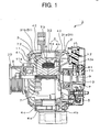
- the vehicle ac generator 1 includes a stator 2, a rotor 3, a housing 4, a rectifier 5, etc.
- the rotor 3 functions as a magnetic field member, rotates together with a shaft 6 and includes a Lundell type pole core 7, a field coil 8, slip rings 9, 10, a mixed flow type fan 11 and a centrifugal fan 12, which respectively function as air blowers.
- the shaft 6 is connected to a pulley 20, which is driven by a vehicle driving engine (not shown).
- the Lundell type pole core 7 is composed of a pair of pole core members.
- the Lundell type pole core 7 includes a boss portion 71, disk portions 72 and twelve magnetic claw poles 73.
- the mixed flow type fan 11 has a base plate 11a that is fixed to an end surface of the pole core 7 by a welder or the like, inclined blades that incline sharply to the base plate 11a and vertical blades and rotates together with the rotor 3.
- the centrifugal fan 12 is disposed at the side remote from the pulley 20 and has only vertical blades that are vertical to a base plate 12a.
- the housing 4 is composed of a front housing 4a and a rear housing 4b and has air intake windows 41 at axial ends thereof and air discharging windows 42 at shoulder portions thereof around and opposite a first and second coil-end groups 31a, 31b.
- the rectifier 5 that converts the ac output power flowing from the stator 2 to dc power is disposed at an end of the ac generator remote from the pulley 20.
- Fig. 2 is a cross-sectional view of a portion of the stator 2.
- Fig. 3 is a perspective schematic diagram illustrating conductor segments to be mounted in the stator core 32.
- the stator 2 functions as an armature and is composed of a stator core 32, a stator winding 31 that is made up of a plurality of conductor segment unit 33 or conductor segments 331, 332, 333 disposed in a plurality of slots formed in the stator core 32 and insulators 34 for insulating the stator winding 31 from the stator core 32.
- the stator core 32 has a plurality of slots 35 opening at the inside surface thereof to accommodate the multi-phase stator winding 31. Thirty six (36) slots 35 are formed at equal intervals to accommodate the three-phase stator winding 31 to correspond to a plurality of magnetic poles.
- the stator winding 31 mounted in the slots 35 of the stator core 32 can be recognized piece by piece.
- An even number (e.g. four) of conductors is disposed in each slot 35.
- Four conductors are disposed in radially aligned layers from the radially inside of the stator core to the radially outside thereof - an innermost layer, an inner middle layer, an outer middle layer and an outermost layer - in each slot 35.
- the conductors are coated by a polyamideimide film.
- Such conductors are connected in a prescribed patterns to form the stator winding 31.
- One end of the conductor in each slot 35 is connected to another in another slot by a continuous turn portion in the first coil-end group 31a and th other of the conductor is connected to another by welding in the second coil-end group 31b.
- Lead wires are extended from the rear portion of the first coil-end group 31a in the axial direction to be connected to the rectifier 5 and in the circumferential direction to be connected to form a neutral point of the Y-connected stator winding 31.
- conductors of special shape are used.
- One of the conductors in each slot 35 (except for the conductors of lead-specialized conductor segments) is paired with another conductor in another slot 35 that is a predetermined pole-pitch spaced apart from it.
- the conductor in certain one of the layers in one of the slots 35 is paired with the conductor in a different layer in another slot 35 that is a predetermined pole-pitch spaced apart from the former slot so that conductors can be regularly disposed to provide a plurality of gaps among the conductors in the coil end groups.
- a conductor 331a in the innermost layer of one of the slots is paired with a conductor 331b in the outermost layer of another slot that is one pole-pitch clockwise spaced apart from the former slot.
- a conductor 332a in the inner middle layer of one of the slots 35 is paired with a conductor 332b in the outer middle layer of another slot that is one pole-pitch clockwise spaced apart from the former slot.
- the paired conductors are connected by a continuous portion forming the turn portion 331c or 332c at an axial end of the stator core 32.
- the continuous turn portion that connects the conductors in the outermost layer and the innermost layer surrounds the continuous turn portion that connects the conductors in the outer middle layer and the inner middle layer.
- the continuous turn portion that connects the paired conductors is surrounded by the continuous turn portion that connects other paired conductors disposed in the same slots as the former paired conductors at an axial end of the stator core 32.
- the continuous turn portion that connects the conductor disposed in the outer middle layer and the conductor disposed in the inner middle layer form a middle coil-end
- the continuous turn portion that connects the conductor disposed in the outermost layer and the conductor disposed in the innermost layer form an outer coil-end.
- the conductor 332a disposed in the inner middle layer in one slot 35 is paired with a conductor 331a'disposed in the innermost layer in another slot 35 that is one pole-pitch clockwise spaced apart from the former slot 35.
- a conductor 331b' disposed in the outermost layer in one slot 35 is paired with the conductor 332a that is disposed in the outer middle layer in another slot 35 that is one pole-pitch clockwise spaced apart from the former slot 35.
- Those conductors are connected by welding to each other at the other axial end of the stator core 32 opposite the continuous turn portion to form joint portions
- the joint portions of the conductor disposed in the outermost layer and the conductor disposed in the outer middle layer and the joint portions of the conductor disposed in the innermost layer and the conductor disposed in the outer middle layer are aligned in the radial direction at the other axial end of the stator core 32.
- the joint portions of the conductors in the outermost layer and the conductors in the outer middle layer and the joint portions of the conductors in the innermost layer and the conductors in the inner middle layer form a double-ring-layer coil-end.
- the joint portions of the conductors are disposed without overlapping at the other axial end of the stator core 32.
- the conductors are provided by U-shaped conductor segments that have an approximately rectangular uniform cross-sectional area (flat rectangular area). As shown in Fig. 3 , the conductor disposed in the innermost layer and the conductor disposed in the outermost layer form a continuous large U-shaped conductor segment 331. Likewise, the conductor disposed in the inner middle layer and the conductor disposed in the outer middle layer form a continuous small U-shaped conductor segment 332. These large and small segments form a basic conductor 33. A plurality of the basic conductor 33 is disposed in the slots 35 in a regular pattern to form a stator winding of double turns around the stator core 32.
- the lead wires of the stator winding are formed from lead-specialized conductor segments (second conductor segments ) 333 that are different from the basic conductor segments (first conductor segments) 331, 332.
- the lead-specialized conductor segment is longer in a the axial direction than the large conductor segments 331 and the small conductor segments 332.
- a lead wire is provided by cutting a portion of the lead-specialized conductor segment 333 after the stator winding 31 is formed.
- the large conductor segments 331 and the small conductor segments 332 are formed from a portion of a continuous conductor wire, which are bent along respective mandrels and taken out thereof.
- the lead-specialized conductor segments 333 for lead wires are formed in a similar manner.
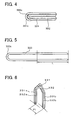
- Fig. 4 illustrates two kinds of the basic segments 33 formed in the forming step.
- the small conductor segment 332 is formed by bending a portion of a conductor wire along a mandrel of a prescribed outside diameter.
- the large conductor segment 331 is formed by bending a portion of a conductor wire along a mandrel of a larger outside diameter than the former mandrel for the small conductor segment 332 so that it surrounds the small conductor segment 332.
- Fig. 5 illustrates the lead-specialized conductor segment.
- the lead-specialized conductor segment 333 is formed into an approximately U-shape, whose axial length is larger than the axial length L of the large conductor segment.
- twisting step The turn portion 332c of the small conductor segment 332 and the turn portion 331c of the large conductor segment 331 are put together so that the latter surrounds the former, and the straight portions of both small and large segments are inserted into a turn-side twisting tool. After the straight portions of the lead-specialized conductor segment 333 are inserted into the twisting tool, the twisting tool is turned while the each top of the turn portion of the large and small conductor segments is restrained by a pressing tool so that the respective straight portions of the conductor segments are moved and twisted in different circumferential direction.
- Fig. 6 is a perspective view illustrating each portion around the turn portion of the large conductor segment 331 and the small conductor segment 332 that are twisted in the twisting step.
- the large conductor segment 331 whose circumferential pitch P1 between the straight portions 331a and 331b in the twisting step is one pole-pitch and the small conductor segment 332 whose circumferential pitch P1 between the straight portions 332a and 332b is one pole-pitch are formed.
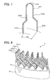
- Fig. 7 is a perspective view illustrating the lead-specialized conductor segment 333 that has a straight portion is twisted in the middle in the twisting step. As illustrated in Fig. 7 , the circumferential pitch P2 between the end portions of the respective straight portions 333a and 333b is made larger than one pole-pitch in the twisting step.
- the lead-specialized conductor segment 333 has longer straight portions 333d, 333e than those of the large and small conductor segments 331, 332, which form a U-shape as a whole.
- the large conductor segments 331, the small conductor segments 332 and the lead-specialized segments 333 are inserted into the slots from portions at one axial end of the stator core 32.
- the straight portions 331a, 332a, 332b' and 331b' of the large conductor segment 331 and the small conductor segments 332, which are the above-described conductors are inserted to one of the slots 35 and aligned in the order from the innermost layer to the outermost layer.
- the straight portions 332b', 331b' are straight portions that are paired with straight portions of the large and small conductor segments inserted in another slot 35 that is one pole-pitch spaced apart.
- the joint portions 331d, 331e which are axial ends of the straight portions 331a, 331b located at the innermost and outermost layers, are bent by a half pole-pitch (e.g. 1.5 slot-pitches) in the direction that the large conductor segment opens out at the second coil-end group 31b, where the joint portions 332d, 332e, which are end portions of the straight portions 332a, 332b located at the inner middle and outer middle layers, are bent by a half pole-pitch (e.g. 1.5 slot-pitches) in the direction that the small conductor segment closes.
- a half pole-pitch e.g. 1.5 slot-pitches
- the second coil-end group 31, the joint portion 331e of the outermost layer and the joint portion 332e of the outer middle layer and the joint portion 332d of the inner middle layer and the joint portion 331d of the innermost layer are welded by a welder, such as a supersonic wave welder or an arc welder, or are soldered to be electrically connected, so that the stator 2 as shown in Fig. 8 can be provided.
- a welder such as a supersonic wave welder or an arc welder
- Fig. 9 is a cross-sectional view illustrating a twisting apparatus that includes a turn-portion twisting tool.
- Fig. 10 is a perspective view illustrating the turn-portion twisting tool with conductor segments mounted therein.
- the twisting apparatus 100 includes the turn-portion twisting tool that is constituted of an inner twisting tool 111 and an outer twisting tool 112, turning mechanisms 113, 114 that respectively turn the inner and outer twisting tools 111, 112, a controller 115, a segment-pressing tool 116, a segment-pushing-up tool 117, a hoisting mechanism 118, etc.
- the inner twisting tool 111 has a plurality of circumferentially aligned pairs of radially aligned holding slots 121 and 122 in which the straight portions 331a, 332a of the large and small conductor segments 331, 332 are respectively inserted.
- the number of the pairs of the holding slots 121, 122 corresponds to the number of the slots 35 of the stator core 2. That is, the thirty six (36) holding slots 121 and the thirty six (36) holding slots 122 are respectively formed in the circumferential direction at equal intervals to be coaxial.
- the outer twisting tool 112 also has a plurality (e.g. 36) of circumferentially aligned pairs of coaxially aligned holding slots 131 and 132.
- the inner twisting tool 111 and the outer twisting tool 112 have circumferentially aligned thirty six groups of radially aligned four-holding-slots 121, 122, 131, 132 in the order from the innermost side thereof.
- the large conductor segments 331 and the small conductor segments 332 with some lead-specialized conductor segments 333 are inserted into all the holding slots 121, 122, 131, 132, and the annular segment pressing tool 116 is moved down toward the inner twisting tool 111 and the outer twisting tool 112 to press the turn portions 331c of the large conductor segments 331. Therefore, in the twisting step, the large conductor segments 331 and the small conductor segments 332 are prevented from jutting up from the holding slots 121, 122, 131, 132 in the axial direction.
- Fig. 11 is a perspective view illustrating the segment pressing tool 116.
- the large conductor segments 331 and the small conductor segments 332 are loaded into the turn portion twisting tool together with the long lead-specialized conductor segments 333. Therefore, if the lead-specialized conductor segments 333 are inserted into the holding slots of the inner and outer twisting tools 111, 112 so that the ends thereof that extend in the direction opposite the turn portion can be leveled with those of the large conductor segments 331 and the small conductor segments 332, the turn portions 333c jut out from the turn portions 331c of the large conductor segments 331.
- the segment pressing tool 116 has a top plate 132 that is provided with a recess 130 for passing the lead-specialized conductor segments 333 in the axial direction, so that the tool 116 does not interfere the lead-specialized conductor segments 333 when the tool 116 presses the turn portion 331c of the large conductor segments 331.
- the top plate 132 has an accommodation space 144 for accommodating a circumferentially movable top plate 120 to partly close the recess 130 at the middle in the cross-section thereof.
- one recess formed at a portion of the segment pressing tool 116 is shown in Fig. 11 , three recesses are formed in the circumferential direction to pass six lead wires that are extended from the Y-connected three-phase stator winding 31.
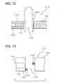
- Fig. 12 is a cross-sectional side view illustrating the segment pressing tool 116 in the circumferential direction.
- Fig. 13 is a fragmentary plan view illustrating a portion around the recess 130.
- the stationary top plate 132 has the accommodation space 144 therein to accommodate the movable top plate 120.
- the above described segment pressing tool 116 moves down to press the turn portions of the large and small conductor segments 331, 332.
- the movable top plate 120 is kept in the accommodation space of the stationary top plate 132 until the segment pressing tool 116 passes the turn portions 333c of the lead-specialized conductor segments 333.
- the movable top plate 120 accommodated by the stationary top plate 132 slides in the circumferential direction to close the recess 130 while segment pressing tool 116 passes the turn portions 333c of the lead-specialized conductor segments 333 and continues moving down.
- the movable top plate 120 moves in the axial direction until the surface thereof in contact with the large conductor segments 331 and others (position of the top plate 120 on the side of the turn portions) reaches the same level as the stationary top plate 132.
- the sliding mechanism 142 is controlled by the controller 115 so that the movable top plate 120 can stop moving down before the segment pressing tool 116 stops moving down.
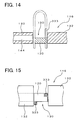
- Fig. 14 is a cross-sectional side view illustrating the segment pressing tool 116 after the movable top plate 120 stops moving.
- Fig. 15 is a fragmentary plan view illustrating the movable top plate 120 after moving, in more detail.
- the movable top plate 120 after moving in the circumferential direction closes the recess 130 for passing the lead-specialized conductor segments 333. Therefore, the turn portions of the large conductor segments 331 and the small conductor segments 332 that are disposed at positions that correspond to the recesses 130 can be pressed by the movable top plate 120.
- the twisting step the axial position of these large and small conductor segments 331, 332 can be surely restrained.
- the movable top plate 120 When the segment pressing tool 116 starts moving down, the movable top plate 120 is accommodated in the accommodation space 144 of the stationary top plate 132, so that the recesses 130 are opened. Therefore, the lead-specialized conductor segments 333 that have a U-shape are not obstructed when they are loaded from the turn-portion side.
- the U-shaped lead-specialized conductor segment can be used even if the straight portions 333a, 333b are disposed to be away from each other in the circumferential direction. As shown in Fig. 16 , two lead wires 333g, 333f can be readily provided only by cutting at least one portion near the turn portion 333c.
- the present invention is not limited to the above embodiment but available for various uses.
- the accommodation space is formed in the stationary top plate 132 of the segment pressing tool 116 in the above described embodiment.
- the movable top plate can be disposed at outside or inside the recess 130 in the radial direction so as to move the movable top plate in the radial direction to close the recess 130.
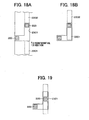
- Fig. 17 is a schematic plan view illustrating a stationary top plate 232 of a segment pressing tool 216.
- the stationary top plate 216 has three recesses 2301, 2302 and 2303 spaced apart from each other in the circumferential direction.
- Two recess 2301 and 2302 have circumferentially extending groove at radially inner portion of the stationary top plate 232 from which the straight portions of the lead-specialized segments 333 can protrude. Therefore, the segment pressing tool 216 can be applied to various stator windings that have various lead-specialized segments 333 whose straight portions have different circumferential pitch.
- Figs. 18A and 18B are schematic diagrams illustrating operation of a movable top plate 2201 in one of the recesses, for example, the recess 2301.
- the movable top plate 2201 is moved in the circumferential direction to press the turn portions of the large conductor segment 231 at the bottom surface of the movable top plate 2201, in the same manner as above. If one of the straight portions of the lead-specialized conductor segment is located at the end of the circumferential groove, only one movable top plate 2201 is necessary to press the turn portions of the large conductor segments.
Landscapes
- Engineering & Computer Science (AREA)
- Manufacturing & Machinery (AREA)
- Power Engineering (AREA)
- Manufacture Of Motors, Generators (AREA)
- Windings For Motors And Generators (AREA)
Applications Claiming Priority (2)
| Application Number | Priority Date | Filing Date | Title |
|---|---|---|---|
| JP2002209004A JP3829769B2 (ja) | 2002-07-18 | 2002-07-18 | 回転電機の固定子巻線の製造方法 |
| JP2002209004 | 2002-07-18 |
Publications (2)
| Publication Number | Publication Date |
|---|---|
| EP1383230A1 EP1383230A1 (en) | 2004-01-21 |
| EP1383230B1 true EP1383230B1 (en) | 2013-09-18 |
Family
ID=29774644
Family Applications (1)
| Application Number | Title | Priority Date | Filing Date |
|---|---|---|---|
| EP03014183.2A Expired - Lifetime EP1383230B1 (en) | 2002-07-18 | 2003-06-24 | Method of manufacturing stator winding of an alternator |
Country Status (4)
| Country | Link |
|---|---|
| US (1) | US7032291B2 (es) |
| EP (1) | EP1383230B1 (es) |
| JP (1) | JP3829769B2 (es) |
| CN (1) | CN1237687C (es) |
Families Citing this family (22)
| Publication number | Priority date | Publication date | Assignee | Title |
|---|---|---|---|---|
| JP3738733B2 (ja) * | 2002-01-18 | 2006-01-25 | 株式会社デンソー | 車両用回転電機の固定子及びその製造方法 |
| US7275300B2 (en) * | 2004-09-27 | 2007-10-02 | General Electric Company | Process for rapid on-demand stator rewinds in electrical generators |
| US20090179511A1 (en) * | 2007-03-22 | 2009-07-16 | Tecnomatic, S.P.A. | Stators having female connectors and methods for forming female connectors integral with the stator winding conductors |
| CN101388583B (zh) * | 2008-10-31 | 2011-09-21 | 天津市天发重型水电设备制造有限公司 | 一种四角焊电机磁极线圈的加工方法 |
| JP5531673B2 (ja) * | 2009-04-06 | 2014-06-25 | 株式会社デンソー | ステータコイルのコイルエンド成形方法および成形装置 |
| JP5392548B2 (ja) * | 2009-04-07 | 2014-01-22 | 株式会社デンソー | ステータコイルのコイルエンド成形方法およびコイルエンド成形装置 |
| IT1400836B1 (it) * | 2010-07-08 | 2013-07-02 | Tecnomatic Spa | Metodo ed apparato per la torcitura di conduttori elettrici a barra, in particolare per avvolgimenti a barra di macchine elettriche. |
| IT1401352B1 (it) * | 2010-07-28 | 2013-07-18 | Tecnomatic Spa | Apparato di torcitura di conduttori elettrici a barra, in particolare per avvolgimenti a barra di macchine elettriche, con sistema di bloccaggio dei conduttori |
| CN102088226B (zh) * | 2010-12-27 | 2012-11-14 | 国营北京曙光电机厂 | 电机转子双层扁铜线圈的绕线方法 |
| CN102360932B (zh) * | 2011-07-20 | 2013-02-13 | 迪斯曼戴克 | 一种用于绕线机的双盘组合式绕线盘 |
| CN102983690B (zh) * | 2012-12-07 | 2015-05-13 | 合肥凯邦电机有限公司 | 单相电机手嵌及机嵌绕线模制造方法 |
| CN103078433B (zh) * | 2012-12-28 | 2015-04-01 | 南车株洲电机有限公司 | 一种插入式转子线圈及成型装置 |
| DE102014213435A1 (de) * | 2014-07-10 | 2016-01-14 | Robert Bosch Gmbh | Verfahren zum Herstellen einer elektrischen Maschine mit Formspulen sowie elektrische Maschine und Herstellungswerkzeug |
| DE102016221355A1 (de) * | 2016-10-28 | 2018-05-03 | Thyssenkrupp Ag | Positioniervorrichtung zum Positionieren von Kupferstäben und Verfahren |
| JP7066466B2 (ja) * | 2018-03-22 | 2022-05-13 | 本田技研工業株式会社 | 捻り曲げ装置 |
| WO2019182144A1 (ja) * | 2018-03-22 | 2019-09-26 | 株式会社小田原エンジニアリング | コイルセグメントの位置決め方法、コイルセグメントの位置決め具及びコイルセグメントの位置決め装置 |
| CN108336875B (zh) * | 2018-05-08 | 2024-08-09 | 成都华川电装有限责任公司 | 一种定子铜线扭形的机械设备 |
| CN118646190A (zh) | 2018-07-30 | 2024-09-13 | 福特全球技术公司 | 一种定子绕线方法和定子铁芯绕组 |
| DE102019211859A1 (de) * | 2019-08-07 | 2021-02-11 | Felsomat Gmbh & Co. Kg | Fertigungssystem und Verfahren zum Fertigen eines Stators mit Stableitern |
| CN110379619A (zh) * | 2019-08-13 | 2019-10-25 | 野邑自动化科技(苏州)有限公司 | 一种串联扁平线圈的绕制方法 |
| CN112491225B (zh) * | 2019-09-11 | 2024-03-01 | 博世汽车部件(苏州)有限公司 | 用于电导线的成形和嵌入装置和方法及定子制造设备 |
| CN114260388B (zh) * | 2021-12-20 | 2023-07-18 | 浙江中车尚驰电气有限公司 | 一种扁线定子端部扭头装置及其方法 |
Family Cites Families (6)
| Publication number | Priority date | Publication date | Assignee | Title |
|---|---|---|---|---|
| US2476743A (en) * | 1946-09-11 | 1949-07-19 | Leece Neville Co | Coil shaping machine |
| DE4031276A1 (de) | 1990-10-04 | 1992-04-09 | Bosch Gmbh Robert | Staender fuer elektrische maschinen und verfahren zu seiner herstellung |
| DE69816263T3 (de) * | 1997-10-16 | 2007-09-13 | Denso Corp., Kariya | Verfahren und vorrichtung zum verdrehen von u-foermigen statorwicklungskoepfen |
| JP3284981B2 (ja) * | 1998-11-02 | 2002-05-27 | 株式会社デンソー | 車両用交流発電機およびそのステータの製造方法 |
| DE10016151A1 (de) | 1999-04-02 | 2000-10-05 | Denso Corp | Verfahren zur Herstellung des Stators einer rotierenden elektrischen Maschine |
| JP3589134B2 (ja) | 2000-01-12 | 2004-11-17 | 株式会社デンソー | ステータ製造方法及びその装置 |
-
2002
- 2002-07-18 JP JP2002209004A patent/JP3829769B2/ja not_active Expired - Lifetime
-
2003
- 2003-06-17 US US10/462,715 patent/US7032291B2/en not_active Expired - Lifetime
- 2003-06-24 EP EP03014183.2A patent/EP1383230B1/en not_active Expired - Lifetime
- 2003-07-18 CN CN03178654.5A patent/CN1237687C/zh not_active Expired - Lifetime
Also Published As
| Publication number | Publication date |
|---|---|
| CN1237687C (zh) | 2006-01-18 |
| JP3829769B2 (ja) | 2006-10-04 |
| US7032291B2 (en) | 2006-04-25 |
| JP2004056880A (ja) | 2004-02-19 |
| US20040074080A1 (en) | 2004-04-22 |
| EP1383230A1 (en) | 2004-01-21 |
| CN1477763A (zh) | 2004-02-25 |
Similar Documents
| Publication | Publication Date | Title |
|---|---|---|
| EP1383230B1 (en) | Method of manufacturing stator winding of an alternator | |
| EP1369979B1 (en) | Method of manufacturing stator winding of rotary electric machine | |
| US6770999B2 (en) | Stator of vehicle ac generator | |
| EP1381141B1 (en) | Rotary electric machine | |
| US6750582B1 (en) | Stator winding having cascaded end loops and increased cooling surface area | |
| EP0967709B1 (en) | Vehicle ac generator's stator and method of manufacturing the same | |
| EP1347559B1 (en) | Manufacturing method for a wound stator of a rotary electric machine | |
| EP1005137A1 (en) | Stator of AC-generator and method of manufacturing the same | |
| US20040119362A1 (en) | Stator winding having cascaded end loops | |
| EP0986160A2 (en) | AC Generator stator for vehicle | |
| JP2004274858A (ja) | 回転電機の巻線の製造方法 | |
| KR100414320B1 (ko) | 회전전기 | |
| US7293342B2 (en) | Method of manufacturing stator for electric motor | |
| EP1341292A2 (en) | Method of manufacturing the winding of an electric machine | |
| EP1317047B1 (en) | Rotary electric machine and manufacturing method thereof | |
| JP2003259613A (ja) | 回転電機の固定子巻線の製造方法 | |
| MXPA98004130A (es) | Arreglo de estator de alternador para vehiculo |
Legal Events
| Date | Code | Title | Description |
|---|---|---|---|
| PUAI | Public reference made under article 153(3) epc to a published international application that has entered the european phase |
Free format text: ORIGINAL CODE: 0009012 |
|
| 17P | Request for examination filed |
Effective date: 20031108 |
|
| AK | Designated contracting states |
Kind code of ref document: A1 Designated state(s): AT BE BG CH CY CZ DE DK EE ES FI FR GB GR HU IE IT LI LU MC NL PT RO SE SI SK TR |
|
| AX | Request for extension of the european patent |
Extension state: AL LT LV MK |
|
| 17Q | First examination report despatched |
Effective date: 20040325 |
|
| AKX | Designation fees paid |
Designated state(s): DE FR GB IT |
|
| APBK | Appeal reference recorded |
Free format text: ORIGINAL CODE: EPIDOSNREFNE |
|
| APBN | Date of receipt of notice of appeal recorded |
Free format text: ORIGINAL CODE: EPIDOSNNOA2E |
|
| APBR | Date of receipt of statement of grounds of appeal recorded |
Free format text: ORIGINAL CODE: EPIDOSNNOA3E |
|
| APAF | Appeal reference modified |
Free format text: ORIGINAL CODE: EPIDOSCREFNE |
|
| APBT | Appeal procedure closed |
Free format text: ORIGINAL CODE: EPIDOSNNOA9E |
|
| GRAP | Despatch of communication of intention to grant a patent |
Free format text: ORIGINAL CODE: EPIDOSNIGR1 |
|
| RIN1 | Information on inventor provided before grant (corrected) |
Inventor name: MURAHASHI, MOTOHIRO Inventor name: KITAKADO, YASUNORI Inventor name: KATO, MITSURU |
|
| INTG | Intention to grant announced |
Effective date: 20130531 |
|
| GRAS | Grant fee paid |
Free format text: ORIGINAL CODE: EPIDOSNIGR3 |
|
| GRAA | (expected) grant |
Free format text: ORIGINAL CODE: 0009210 |
|
| AK | Designated contracting states |
Kind code of ref document: B1 Designated state(s): DE FR GB IT |
|
| REG | Reference to a national code |
Ref country code: GB Ref legal event code: FG4D |
|
| REG | Reference to a national code |
Ref country code: DE Ref legal event code: R096 Ref document number: 60344932 Country of ref document: DE Effective date: 20131114 |
|
| REG | Reference to a national code |
Ref country code: DE Ref legal event code: R097 Ref document number: 60344932 Country of ref document: DE |
|
| PLBE | No opposition filed within time limit |
Free format text: ORIGINAL CODE: 0009261 |
|
| STAA | Information on the status of an ep patent application or granted ep patent |
Free format text: STATUS: NO OPPOSITION FILED WITHIN TIME LIMIT |
|
| 26N | No opposition filed |
Effective date: 20140619 |
|
| REG | Reference to a national code |
Ref country code: DE Ref legal event code: R097 Ref document number: 60344932 Country of ref document: DE Effective date: 20140619 |
|
| REG | Reference to a national code |
Ref country code: FR Ref legal event code: PLFP Year of fee payment: 14 |
|
| REG | Reference to a national code |
Ref country code: FR Ref legal event code: PLFP Year of fee payment: 15 |
|
| REG | Reference to a national code |
Ref country code: FR Ref legal event code: PLFP Year of fee payment: 16 |
|
| PGFP | Annual fee paid to national office [announced via postgrant information from national office to epo] |
Ref country code: IT Payment date: 20220627 Year of fee payment: 20 Ref country code: GB Payment date: 20220621 Year of fee payment: 20 Ref country code: DE Payment date: 20220620 Year of fee payment: 20 |
|
| PGFP | Annual fee paid to national office [announced via postgrant information from national office to epo] |
Ref country code: FR Payment date: 20220628 Year of fee payment: 20 |
|
| REG | Reference to a national code |
Ref country code: DE Ref legal event code: R071 Ref document number: 60344932 Country of ref document: DE |
|
| REG | Reference to a national code |
Ref country code: GB Ref legal event code: PE20 Expiry date: 20230623 |
|
| PG25 | Lapsed in a contracting state [announced via postgrant information from national office to epo] |
Ref country code: GB Free format text: LAPSE BECAUSE OF EXPIRATION OF PROTECTION Effective date: 20230623 |