EP1383016A2 - Motorsteuerungssystem - Google Patents
Motorsteuerungssystem Download PDFInfo
- Publication number
- EP1383016A2 EP1383016A2 EP03253870A EP03253870A EP1383016A2 EP 1383016 A2 EP1383016 A2 EP 1383016A2 EP 03253870 A EP03253870 A EP 03253870A EP 03253870 A EP03253870 A EP 03253870A EP 1383016 A2 EP1383016 A2 EP 1383016A2
- Authority
- EP
- European Patent Office
- Prior art keywords
- driven member
- control system
- motor control
- constants
- host controller
- Prior art date
- Legal status (The legal status is an assumption and is not a legal conclusion. Google has not performed a legal analysis and makes no representation as to the accuracy of the status listed.)
- Withdrawn
Links
Images


Classifications
-
- G—PHYSICS
- G05—CONTROLLING; REGULATING
- G05B—CONTROL OR REGULATING SYSTEMS IN GENERAL; FUNCTIONAL ELEMENTS OF SUCH SYSTEMS; MONITORING OR TESTING ARRANGEMENTS FOR SUCH SYSTEMS OR ELEMENTS
- G05B19/00—Program-control systems
- G05B19/02—Program-control systems electric
- G05B19/18—Numerical control [NC], i.e. automatically operating machines, in particular machine tools, e.g. in a manufacturing environment, so as to execute positioning, movement or co-ordinated operations by means of program data in numerical form
- G05B19/19—Numerical control [NC], i.e. automatically operating machines, in particular machine tools, e.g. in a manufacturing environment, so as to execute positioning, movement or co-ordinated operations by means of program data in numerical form characterised by positioning or contouring control systems, e.g. to control position from one programmed point to another or to control movement along a programmed continuous path
-
- B—PERFORMING OPERATIONS; TRANSPORTING
- B30—PRESSES
- B30B—PRESSES IN GENERAL
- B30B1/00—Presses, using a press ram, characterised by the features of the drive therefor, pressure being transmitted directly, or through simple thrust or tension members only, to the press ram or platen
- B30B1/10—Presses, using a press ram, characterised by the features of the drive therefor, pressure being transmitted directly, or through simple thrust or tension members only, to the press ram or platen by toggle mechanism
- B30B1/103—Presses, using a press ram, characterised by the features of the drive therefor, pressure being transmitted directly, or through simple thrust or tension members only, to the press ram or platen by toggle mechanism operated by screw means
Definitions
- the present invention relates to a motor control system for controlling a servomotor for driving an axis of a driving mechanism of an industrial machine such as a robot, a machine tool, an injection molding machine or a press machine.
- a driving axis for driving a driven member is driven by a servomotor such that a position and/or a velocity of the driving axis is feedback controlled by position control processing and velocity control processing.
- operation constants such as gains, for use in mathematical operations in the position control processing and the velocity control processing have been set to fixed values.
- the position control processing and/or the velocity control processing is performed using the fixed operation constants even in a control system where stability of the system varies in dependence on a position of the driving axis (a position of the driven member and a rotational position of the servomotor).
- a ratio between the position feedback and the velocity feedback changes in dependence of the position of the driving axis. Since this is equivalent to an effect that a reduction ratio of the transmission mechanism dynamically changes in accordance with the position of the driven member, the control system becomes stable at a position of a relatively large reduction ratio and unstable at a position of a relatively small reduction ratio.
- the operation constants have been predetermined in view of the stability of the system at the position where the dynamic reduction ratio of the transmission mechanism is relatively small.
- the operation at the position where the dynamic reduction ratio is relative large is made slow, which delays the whole cycle time of motion of the machine.
- An object of the present invention is to provide a motor control system capable of improving stability of control and rapidness of operation even in the case where the stability of the control system varies in dependence with the position of the drive axis.
- the present invention provides a motor control system for controlling a servomotor for driving a driven member through a transmission mechanism for mechanically connecting the servomotor and the driven member.
- the motor control system comprises: a servo controller having a position control section for performing position control processing for feedback controlling a position of the driven member, and a velocity control section for performing velocity control processing for feedback controlling a velocity of the driven member; and operation constant varying means for varying operation constants for the position control processing to be performed by the position control section and/or the velocity control processing to be performed by the velocity control section in accordance with a present position of the driven member.
- the operation constant varying means may vary the operation constants in accordance with a present rotational position of the servomotor mechanically connected with the driven member by the transmission mechanism.
- the motor controller may comprise a host controller for commanding the servo controller.
- the present position of the driven member may be determined based on a position command issued from the host controller or a position feedback signal from a detector for detecting a position of the driven member.
- the present rotational position of the servomotor may be determited based on a position command issued from the host controller or a position feedback signal from a detector for detecting a rotational position of the servomotor.
- the operation constant varying means may comprise storage means for storing data representing relation between the position of the driven member or the rotational position of the servomotor and the operation constants, and may determine values of the operation constants for the present position of the driven member or the present rotational position of the servomotor using the stored data.
- the operation constant varying means may comprise storage means for storing a mathematical equation representing a relation between the position of the driven member or the rotational position of the servomotor and the operation constants, and for determining values of the operation constants for the present position of the driven member or the present rotational position of the servomotor using the stored mathematical equation.
- the storage means storing the data or the mathematical equation may be provided in the host controller.
- the operation constant varying means may start varying of the operation constants upon receipt of a signal from an external device or a signal produced by internal processing in the motor control system or a program command.
- the operation constant varying means may determine values of the operation constants to be varied smoothly.
- the operation constants for the position control section and/or the velocity control section may be set to upper limit values until an initial position of the driven member is established after a power supply to the motor control system is turned on.
- the driven member may be a mold of an electric press machine for performing a press work.
- the operation constants have different values at a position where the press work is performed and at a position where the press work is not performed.
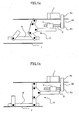
- FIGS. 1a and 1b schematically show operational states of an electric press machine as an example of an industrial machine in which a transmission mechanism for mechanically connecting a servomotor and a driven member includes a nonlinear element such that a stability of a control system of the machine varies in dependence on a position of the driven member.
- a transmission mechanism from a servomotor 1 to an upper mold 6 for press working includes a linkage mechanism 5 as a nonlinear transmission element.
- a rotational motion of an output shaft of the servomotor 1 is transmitted to a ball screw 3 through pulleys 2a, 2c and a timing belt 2b so that the ball screw 3 is rotationally driven.
- a ball nut 4 engaged with the ball screw 3 is fixed to one end of the linkage mechanism 5.
- the upper mold 6 is mounted at the other end of the linkage mechanism 5 such that the upper mold 6 is moved upward away from/downward towards a plate material 7 placed on a lower mold (not shown) to perform the press working.
- FIG. 1a shows a state where the upper mold 6 is moved to a top dead point of a motion stroke of the linkage mechanism 5 and
- FIG. 1b shows a state where the upper mold 6 is moved to a bottom dead point of the motion stroke.
- FIG. 2 relation between the rotational position of the motor 1 and the position of the driven member, i.e. the upper mold 6 is shown in FIG. 2.
- the position of the driven member at the top dead point and the corresponding rotational position of the motor are set to "0" on an axis of ordinate and an axis of abscissa, respectively, with directions from the top dead point to the bottom dead point set as positive directions.
- the relation between the rotational position of the motor and the position of the driven member should be represented by a straight line as shown by the dotted line in FIG. 2.
- the linkage mechanism 5 as a nonlinear transmission element is intervened between the motor and the driven member, the relation between the rotational position of the motor and the position of the driven member is nonlinear as represented by the continuous line in FIG. 2. This relation is determined in dependence on characteristics of the transmission mechanism from the motor to the driven member.
- a rate of change of the position of the driven member with respect to change of the rotational position of the motor varies in dependence on the rotational position of the motor such that the rate of change decreases as the rotational position of the motor moves closer to the bottom dead point. Accordingly, the stability of the control system in the vicinity of the top dead point differs from that in the vicinity of the bottom dead point. Since a mechanical inertia of the transmission mechanism driven by the motor in the vicinity of top dead point is larger than that in the vicinity of the bottom dead point, an electric current of the motor 1 is increased to obtain a constant acceleration in the vicinity of top dead point. Further, since the rotational position of the motor may be fluctuated by a vibration of the upper mold 2 or the transmission mechanism in the vicinity of the top dead point, the control system tends to be influenced by disturbances.
- the operation constants for the position control processing and the velocity control processing have been predetermined to be fixed values so that a sufficient stability of the control system is obtained in the vicinity of the top dead point. Since the position control processing and the velocity control processing are performed using thus determined operation constants during the control even in the vicinity of the bottom dead point where rapidness of positional response and the positioning precision of the driven member are required, the rapidness of response of the control system and precision and efficiency of the press working are lowered.
- the operation constants such as a position gain in the position control processing and a proportional gain and an integral gain in the velocity control processing are varied in accordance with the position of the driven member during the control.
- values of the operation constants are determined to secure sufficient stability in the vicinity of the top dead point and quick response and high positioning precision in the vicinity of the bottom dead point.
- Optimum values of multiplier factors, by which reference operation constants are respectively multiplied, in accordance with the position of the upper mold 6 are determined as shown in FIG. 3 based on analysis of the characteristic of the transmission mechanism.
- characteristic curves of the respective multiplier factors for the position control processing and the velocity control processing are shown with an axis of ordinate representing values of the respective multiplier factors and an axis of abscissa representing a position of the driven member.
- the multiplier factor of the operation constants for the position control processing is set to be relatively large.
- the multiplier factor for the position feedback control is set to be relatively small and the multiplier factor for the velocity control processing is set to be relatively large.
- the values of the reference operation constants are stored, and also the above characteristic curves of the multiplier factors with respect to the position of the driven member are stored in the form of tables or registered in the form of equations, so that optimum values of the operation constants are calculated by multiplying the reference operation constants by the multiplier factors to vary the operation constants in accordance with the present position of the driven member in the control of the machine.
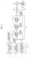
- FIG. 4 is a functional diagram of a motor control system according an embodiment of the present invention.
- the motor control system comprises a host controller 10 and a servo controller 20 which are constituted by respective processors. An output of the servo controller 20 is fed to a servo amplifier 30 to drivingly control the servomotor 31.
- the servomotor 31 is operatively connected to a driven member 32 thorough a transmission mechanism including a nonlinear element such as the linkage mechanism 5 as shown in FIGS. 1a and 1b, so that the position and velocity of the driven member 32 is controlled.
- a position/velocity detector 33 is provided for detecting the position and velocity of the driven member 32 and a position feedback signal and a velocity feedback signal are fed to the servo controller 20, and the position feedback signal is also fed to the host controller 10.
- the host controller 10 comprises a position command value calculating section 11 for calculating a position command to command a motion of the driven member 32 based on a program, a position information managing section 12 for managing a present position of the driven member 32 and a multiplier factor calculating section 13.
- the position information managing section 12 has a present position register for storing the present position of the driven member 32.
- the present position of the driven member 32 is obtained based on the position feedback signal from the position/velocity detector 33 and/or based on the position command issued from the position command operating section 11.
- the multiplier factor calculating section 13 stores data of characteristic curves of the multiplier factors of the operation constants with respect to the position of the driven member as shown in FIG. 3 in the form of the data tables or the mathematical equations.
- the servo controller 20 comprises a position control section 21 to which the position command is inputted from the host controller 10 at every predetermined period, a velocity control section 22 and a current control section 23.
- the multiplier factors of the operation constants for the position control section 21 and the velocity control section 22 are received from the host controller 10 at every predetermined period.
- the position control section 21 and the velocity control section 22 receive the position feedback signal and the velocity feedback signal, respectively, from the position/velocity detector 33, and the current control section 23 receives a current feedback signal form a current detector (not shown) provided in the servo amplifier 30.
- the above configuration of the motor control system can be constituted by utilizing a conventional control system for a machine tool or a robot controller,by providing the multiplier factor calculating section 13 in the host controller 10 so that the multiplier factors for operation constants obtained by the multiplier factor calculating section 13 are sent to the servo controller 20.
- the operation constants (the position gain of the position control processing, the proportional gain and the integral gain ofthe velocity control processing) for the servo controller 20 are set to the upper limit values until an initial position of the driven member 32 is established to facilitate the establishment of the initial position of the driven member 32. After the position of the driven member 32 is established, the operation constants are set to the predetermined reference values.
- the processor of the host controller 10 calculates a position command for moving the driven member based on an operation program and outputs the position command to the servo control section 20 at every predetermined period (Step S1; processing to be performed by the position command calculating section 11 in FIG. 4). Then, the present position of the driven member 32 is stored in the present position register by adding the value of the position command outputted to the servo controller 20 to the value of the present position register to be accumulated. Alternatively, the present position of the driven member 32 may be obtained by summing values of the position feedback signal from the position/velocity detector 33 in the present position register (Step S2: processing to be performed by the present position information managing section 12 in FIG. 4).
- Step S2 If the adjustment of the operation constants is not commanded to be performed, the procedure is terminated at the above processing at Step S2. If the adjustment of the operation constants is commanded to be performed by an external input by a manual operation on an operation panel, or a command designated in a machining program, or a command issued as a result of processing in the motor control system with predetermined conditions fulfilled, the procedure proceeds further to Step S3.
- Step S3 respective multiplier factors of the operation constants for the position control section 21 and the velocity control section 22 for the present position of the driven member 32 are obtained using the data tables or the equations. The obtained values of the multiplier factors of the operation constants are outputted to the servo controller 20 at every predetermined period. The processing at this step is performed by the multiplier factor calculating section 13 in the functional block diagram of FIG. 4.
- the processor of the servo controller 20 executes the processing as shown in FIG. 6 at every predetermined processing period.
- the values of the multiplier factors of the operation constants for the position control section 21 and the velocity control section 22 received from the host controller 10 are respectively multiplied by the reference operation constants (the position gain for the position control processing and the proportional gain and the integral gain in the velocity control processing) which are predetermined for the position control section 21 and the velocity control section 22, to obtain and update the values of the operation constants for the present processing period (Step S4).
- the reference operation constants the position gain for the position control processing and the proportional gain and the integral gain in the velocity control processing
- the position control section 21 obtains a position deviation based on the position command issued from the position command calculating section 11 of the host controller 10 and the position feedback signal from the position/velocity detector 33, and multiplies the position deviation by the updated position gain to obtain a velocity command.
- the velocity control section 22 obtains a velocity deviation based on the velocity command from the position control section 21 and the velocity feedback signal from the position/velocity detector 33, and performs the velocity control processing using the velocity deviation and the updated operation constants (the proportional gain and the integral gain) to obtain a torque command (current command).
- the velocity control section 23 is designed to perform the proportional plus integral (IP) control
- IP proportional plus integral
- Step S6 the current control section 23 performs the current control processing based on the torque command (current command) from the velocity control section 22 and the current feedback value from the current detector, to control the servomotor 31 through the amplifier 30, so that the position and velocity of the driven member 32 are controlled.
- the foregoing embodiment adopts a full-closed loop control system in which the feedback controls are performed based on the feedback signals of the position and velocity of the driven member 32 detected by the position/velocity detector 33 for detecting the position and velocity of the driven member 32.
- the present invention is also applicable to a semi-closed loop control system in which the feedback controls are performed based on feedback signals from a position/velocity detector for detecting the position and velocity of the servomotor 31.
- the data of the multiplier factor of the operation constants with respect to the position of the driven member as shown in FIG. 3 is used for the position control processing, and in the case of detecting the position of the motor to be fed back, the data of the multiplier factor of the operation constants with respect to the rotational position of the motor is used for the velocity control processing.
- both of the operation constants for the position control processing by the position control section 21 and for the velocity control processing by the velocity control section 22 are varied in the control processing.
- the operation constants for only one of the position control processing and the velocity control processing may be varied in accordance with the position of the driven member or the rotational position of the motor in dependence on kind, characteristic and usage of the machine of the servomotor to be controlled by the motor control system.
- the multiplier factor calculating section 13 is provided in the host controller in the foregoing embodiment, but the multiplier factor calculating section may be provided in the servo controller 20.
- data of the position of the driven member or the rotational position of the servomotor may be transferred to the servo controller 20 from the host controller 10 at every predetermined period, or the servo controller 20 may have a register for storing the position of the driven member or the rotational position of the motor based on the position command issued from the host controller 10 or the position feedback signal so as to determine the multiplier factors of the operation constants based on the stored position data to update the operation constants for the position, velocity and current control sections.
- the data table or mathematical equation for obtaining the multiplier factors of the operation constants are stored in the foregoing embodiment, but the data table or mathematical equation representing relation between values of the operation constants and the position of the driven member or the rotational position of the servomotor may be stored without using the multiplier factors and the reference operation constants.
- values of the multiplier factors of the operation constants may be adjusted so as to vary smoothly.
- n-number (n: an integer not smaller than 2) of registers R1, R2, ..., Rn for storing the values of the multiplier factors obtained based on the data table or the mathematical equations, and operating means for summing outputs of all the registers and dividing the sum by "n" are provided in the multiplier factor calculating section 13 of the host controller 10, so that output of the operating means is used as the value of the multiplier factors at the present processing period (processing at Step S3 in FIG. 5).
- the reference values of the multiplier factors are stored as initial values of the registers R1, R2, ..., Rn, and when the command for varying the operation constants issues, the values of the registers are shifted such that the value stored in the register Rn-1 is stored in the register Rn, the value stored in the register Rn-2 is stored in the register Rn-1, ..., the value stored in the register R1 is stored in the register R2, and the value of the multiplier factors (or the operation constants) is stored in the register R1.
- the values stored in the registers R1, R2, ..., Rn are summed up and the sum is divided by the number "n", and the resultant quotient is outputted as the value of the multiplier factors (or the operation constants) for the present processing period.
- the output of the operation means reaches the value after "n" processing periods.
- stability and rapidness of the motor control are secured even in a case where the control characteristic of the driving system changes in accordance with the position of the driven member or the rotational position of the servomotor, e.g. in a driving system including a nonlinear transmission element such as a link mechanism.
Landscapes
- Engineering & Computer Science (AREA)
- Human Computer Interaction (AREA)
- Manufacturing & Machinery (AREA)
- Physics & Mathematics (AREA)
- General Physics & Mathematics (AREA)
- Automation & Control Theory (AREA)
- Control Of Position Or Direction (AREA)
- Control Of Electric Motors In General (AREA)
- Numerical Control (AREA)
- Control Of Presses (AREA)
Applications Claiming Priority (2)
| Application Number | Priority Date | Filing Date | Title |
|---|---|---|---|
| JP2002189148A JP2004030500A (ja) | 2002-06-28 | 2002-06-28 | モータ制御装置 |
| JP2002189148 | 2002-06-28 |
Publications (1)
| Publication Number | Publication Date |
|---|---|
| EP1383016A2 true EP1383016A2 (de) | 2004-01-21 |
Family
ID=29774291
Family Applications (1)
| Application Number | Title | Priority Date | Filing Date |
|---|---|---|---|
| EP03253870A Withdrawn EP1383016A2 (de) | 2002-06-28 | 2003-06-19 | Motorsteuerungssystem |
Country Status (3)
| Country | Link |
|---|---|
| US (1) | US7248014B2 (de) |
| EP (1) | EP1383016A2 (de) |
| JP (1) | JP2004030500A (de) |
Families Citing this family (13)
| Publication number | Priority date | Publication date | Assignee | Title |
|---|---|---|---|---|
| JP3991229B2 (ja) * | 2004-01-13 | 2007-10-17 | 村田機械株式会社 | 搬送台車システム |
| JP4074999B2 (ja) * | 2004-01-13 | 2008-04-16 | 村田機械株式会社 | 搬送台車システム |
| JP2005219133A (ja) * | 2004-02-03 | 2005-08-18 | Fanuc Ltd | ロボット用サーボモータ制御装置およびロボット |
| JP2006059132A (ja) * | 2004-08-20 | 2006-03-02 | Tomoe Tech Res Co | バルブポジショナ,バルブ駆動装置 |
| JP2008087073A (ja) * | 2007-12-25 | 2008-04-17 | Fanuc Ltd | ダイクッション機構の制御装置 |
| JP5455737B2 (ja) * | 2010-03-26 | 2014-03-26 | 三菱電機株式会社 | 駆動制御装置 |
| US20120067374A1 (en) * | 2010-09-21 | 2012-03-22 | Avery Dennison Corporation | Vacuum Storage Bag Having Assorted Monitoring Means |
| JP6035755B2 (ja) * | 2012-02-01 | 2016-11-30 | セイコーエプソン株式会社 | プレス加工方法 |
| JP5411978B2 (ja) * | 2012-06-04 | 2014-02-12 | ファナック株式会社 | ボールネジの伸縮量を補正する機能を備えたサーボ制御装置 |
| JP5667147B2 (ja) * | 2012-10-30 | 2015-02-12 | ファナック株式会社 | ボールねじの伸縮量に基づいて補正処理を実行するサーボ制御装置 |
| JP5689494B2 (ja) | 2013-03-28 | 2015-03-25 | ファナック株式会社 | 位置制御ゲインを生成する上位制御装置 |
| CN104007698B (zh) * | 2014-05-27 | 2017-01-18 | 南京航空航天大学 | 伺服压力机加工工艺曲线轨迹规划方法 |
| EP3283264A1 (de) * | 2015-04-16 | 2018-02-21 | Bohnert Equipment Company, Inc. | Fassreifenansteuerungsvorrichtung und elektrischer antrieb |
Family Cites Families (33)
| Publication number | Priority date | Publication date | Assignee | Title |
|---|---|---|---|---|
| JPS5597621A (en) * | 1979-01-18 | 1980-07-25 | Mitsubishi Electric Corp | Remote control system for automatic operation of computer system |
| US4378592A (en) * | 1980-08-29 | 1983-03-29 | Danly Machine Corporation | Computer directed loading and unloading devices |
| JPS62190501A (ja) | 1986-02-17 | 1987-08-20 | Sumitomo Heavy Ind Ltd | サ−ボシステム |
| JPS62203203A (ja) * | 1986-03-03 | 1987-09-07 | Sumitomo Electric Ind Ltd | サ−ボ回路 |
| US4841208A (en) * | 1986-09-11 | 1989-06-20 | Toshiba Kikai Kabushi Kaisha | Position control system including a quick response control |
| JPS63274395A (ja) * | 1987-04-30 | 1988-11-11 | Fujitsu Ltd | 磁気ヘッド位置決め制御方式 |
| JPH01106120A (ja) | 1987-10-19 | 1989-04-24 | Nec Corp | デジタルサーボ装置 |
| JP2797330B2 (ja) | 1988-08-26 | 1998-09-17 | 神鋼電機株式会社 | 可変ゲイン積分比例補償器 |
| JPH0438310Y2 (de) * | 1988-12-08 | 1992-09-08 | ||
| JP2708928B2 (ja) | 1990-04-04 | 1998-02-04 | 三菱電機株式会社 | モータの位置決め制御装置 |
| JPH0438310A (ja) | 1990-05-31 | 1992-02-07 | Yoshio Kuno | 道路表示 |
| JP2731973B2 (ja) * | 1990-07-30 | 1998-03-25 | 株式会社日立製作所 | 電動機制御システム |
| US5371450A (en) * | 1992-08-10 | 1994-12-06 | Sumitomo Heavy Industries, Ltd. | Control unit capable of smoothly carrying out a switching operation between position and pressure feedback control systems |
| US5475291A (en) * | 1992-12-10 | 1995-12-12 | Matsushita Electric Industrial Co., Ltd. | Adjustment device for adjusting control parameters of a servo motor and an adjustment method therefor |
| US5508596A (en) * | 1993-10-07 | 1996-04-16 | Omax Corporation | Motion control with precomputation |
| JPH07175405A (ja) * | 1993-12-16 | 1995-07-14 | Yaskawa Electric Corp | サーボ制御装置のパラメータ指定方法 |
| JPH07261773A (ja) * | 1994-03-17 | 1995-10-13 | Amada Metrecs Co Ltd | Nc工作機械のための能動消音システム |
| JPH08161004A (ja) * | 1994-12-09 | 1996-06-21 | Toshiba Corp | Pidコントローラ |
| JPH08286758A (ja) * | 1995-04-11 | 1996-11-01 | Canon Inc | 位置決め装置 |
| US5684375A (en) * | 1995-06-20 | 1997-11-04 | Allen-Bradley Company, Inc. | Method and apparatus for tuning a motion control system |
| US5714831A (en) * | 1995-11-13 | 1998-02-03 | Wisconsin Alumni Research Foundation | Method and apparatus for improved control of piezoelectric positioners |
| JP3351990B2 (ja) * | 1997-05-27 | 2002-12-03 | オークマ株式会社 | ボールネジ駆動系の位置制御装置 |
| US6233497B1 (en) * | 1997-09-18 | 2001-05-15 | Mitsubishi Denki Kabushiki Kaisha | Contact detecting method and an apparatus for the same |
| JP3628901B2 (ja) * | 1999-03-15 | 2005-03-16 | アイダエンジニアリング株式会社 | サーボプレス機械の自動パラメータ調節装置 |
| US6961628B2 (en) * | 1999-04-16 | 2005-11-01 | Siemens Energy & Automation, Inc. | Method and apparatus for tuning compensation parameters |
| US6198246B1 (en) * | 1999-08-19 | 2001-03-06 | Siemens Energy & Automation, Inc. | Method and apparatus for tuning control system parameters |
| JP2001092531A (ja) * | 1999-09-20 | 2001-04-06 | Hitachi Via Mechanics Ltd | 位置決め制御装置 |
| EP1132790B1 (de) * | 2000-02-10 | 2003-06-18 | Fanuc Ltd | Steuervorrichtung für eine Maschine |
| JP2001242908A (ja) * | 2000-02-28 | 2001-09-07 | Keyence Corp | 表示装置、その通信方法、データ作成装置、データ作成方法およびデータ作成プログラムを記録した記録媒体 |
| JP3492583B2 (ja) * | 2000-03-27 | 2004-02-03 | ファナック株式会社 | サーボ制御装置 |
| JP3789283B2 (ja) * | 2000-04-26 | 2006-06-21 | アイダエンジニアリング株式会社 | サーボプレス |
| KR100447052B1 (ko) * | 2000-11-01 | 2004-09-04 | 미쓰비시덴키 가부시키가이샤 | 서보 제어장치 |
| WO2002049201A1 (fr) * | 2000-12-14 | 2002-06-20 | Mitsubishi Denki Kabushiki Kaisha | Dispositif d'evaluation des constantes d'une machine |
-
2002
- 2002-06-28 JP JP2002189148A patent/JP2004030500A/ja active Pending
-
2003
- 2003-06-16 US US10/461,331 patent/US7248014B2/en not_active Expired - Fee Related
- 2003-06-19 EP EP03253870A patent/EP1383016A2/de not_active Withdrawn
Also Published As
| Publication number | Publication date |
|---|---|
| US7248014B2 (en) | 2007-07-24 |
| US20040000890A1 (en) | 2004-01-01 |
| JP2004030500A (ja) | 2004-01-29 |
Similar Documents
| Publication | Publication Date | Title |
|---|---|---|
| US7248014B2 (en) | Motor control system | |
| US6861814B2 (en) | Control parameter automatic adjustment apparatus | |
| US6507165B2 (en) | Controller for machine | |
| US7902780B2 (en) | Inertia estimating controller and control system | |
| US4914365A (en) | Control device for servo motor | |
| US7366576B2 (en) | Position control device and position control method for machine tools | |
| CN101656507B (zh) | 电动机控制装置 | |
| US8198851B2 (en) | Motor controller | |
| CN103167737B (zh) | 电动机控制装置 | |
| US5986422A (en) | Control mode changing over method for servo control system | |
| CN109940618A (zh) | 一种基于正交模糊pid的串联机械手驱动系统运动控制方法 | |
| US7034491B2 (en) | Numerical controller | |
| JPH0722873B2 (ja) | 送り軸の位置制御装置 | |
| JP2950149B2 (ja) | オートチューニングコントローラ | |
| US20050222695A1 (en) | Sliding mode controller position control device | |
| US4864209A (en) | Negative feedback control system | |
| WO2008072426A1 (ja) | プレス機械とその制御装置及び制御方法 | |
| CN114123906A (zh) | 永磁同步电机惯量辨识方法、系统及存储介质 | |
| US6975086B1 (en) | Positioning control method | |
| JP2011147201A (ja) | 電動機制御装置 | |
| JP3226413B2 (ja) | 数値制御装置 | |
| JP3313144B2 (ja) | サーボモータ駆動方式プレス機械の駆動制御装置 | |
| JP2002163006A (ja) | 電動機制御装置および制御方法 | |
| JPWO2000052543A1 (ja) | 位置決め制御方法 | |
| JPH1063339A (ja) | 数値制御工作機械の制御装置 |
Legal Events
| Date | Code | Title | Description |
|---|---|---|---|
| PUAI | Public reference made under article 153(3) epc to a published international application that has entered the european phase |
Free format text: ORIGINAL CODE: 0009012 |
|
| AK | Designated contracting states |
Kind code of ref document: A2 Designated state(s): AT BE BG CH CY CZ DE DK EE ES FI FR GB GR HU IE IT LI LU MC NL PT RO SE SI SK TR |
|
| AX | Request for extension of the european patent |
Extension state: AL LT LV MK |
|
| RAP1 | Party data changed (applicant data changed or rights of an application transferred) |
Owner name: FANUC LTD |
|
| PUAL | Search report despatched |
Free format text: ORIGINAL CODE: 0009013 |
|
| PUAF | Information related to the publication of a search report (a3 document) modified or deleted |
Free format text: ORIGINAL CODE: 0009199SEPU |
|
| STAA | Information on the status of an ep patent application or granted ep patent |
Free format text: STATUS: THE APPLICATION HAS BEEN WITHDRAWN |
|
| AK | Designated contracting states |
Kind code of ref document: A3 Designated state(s): AT BE BG CH CY CZ DE DK EE ES FI FR GB GR HU IE IT LI LU MC NL PT RO SE SI SK TR |
|
| AX | Request for extension of the european patent |
Extension state: AL LT LV MK |
|
| D17D | Deferred search report published (deleted) | ||
| 18W | Application withdrawn |
Effective date: 20070116 |