EP1382906A2 - Combustion control method and apparatus for waste incinerators - Google Patents
Combustion control method and apparatus for waste incinerators Download PDFInfo
- Publication number
- EP1382906A2 EP1382906A2 EP03078136A EP03078136A EP1382906A2 EP 1382906 A2 EP1382906 A2 EP 1382906A2 EP 03078136 A EP03078136 A EP 03078136A EP 03078136 A EP03078136 A EP 03078136A EP 1382906 A2 EP1382906 A2 EP 1382906A2
- Authority
- EP
- European Patent Office
- Prior art keywords
- concentration
- exhaust gas
- combustion air
- secondary combustion
- control
- Prior art date
- Legal status (The legal status is an assumption and is not a legal conclusion. Google has not performed a legal analysis and makes no representation as to the accuracy of the status listed.)
- Withdrawn
Links
Images


Classifications
-
- F—MECHANICAL ENGINEERING; LIGHTING; HEATING; WEAPONS; BLASTING
- F23—COMBUSTION APPARATUS; COMBUSTION PROCESSES
- F23N—REGULATING OR CONTROLLING COMBUSTION
- F23N5/00—Systems for controlling combustion
- F23N5/02—Systems for controlling combustion using devices responsive to thermal changes or to thermal expansion of a medium
- F23N5/022—Systems for controlling combustion using devices responsive to thermal changes or to thermal expansion of a medium using electronic means
-
- F—MECHANICAL ENGINEERING; LIGHTING; HEATING; WEAPONS; BLASTING
- F23—COMBUSTION APPARATUS; COMBUSTION PROCESSES
- F23G—CREMATION FURNACES; CONSUMING WASTE PRODUCTS BY COMBUSTION
- F23G5/00—Incineration of waste; Incinerator constructions; Details, accessories or control therefor
-
- F—MECHANICAL ENGINEERING; LIGHTING; HEATING; WEAPONS; BLASTING
- F23—COMBUSTION APPARATUS; COMBUSTION PROCESSES
- F23G—CREMATION FURNACES; CONSUMING WASTE PRODUCTS BY COMBUSTION
- F23G5/00—Incineration of waste; Incinerator constructions; Details, accessories or control therefor
- F23G5/50—Control or safety arrangements
-
- F—MECHANICAL ENGINEERING; LIGHTING; HEATING; WEAPONS; BLASTING
- F23—COMBUSTION APPARATUS; COMBUSTION PROCESSES
- F23N—REGULATING OR CONTROLLING COMBUSTION
- F23N3/00—Regulating air supply or draught
- F23N3/002—Regulating air supply or draught using electronic means
-
- F—MECHANICAL ENGINEERING; LIGHTING; HEATING; WEAPONS; BLASTING
- F23—COMBUSTION APPARATUS; COMBUSTION PROCESSES
- F23N—REGULATING OR CONTROLLING COMBUSTION
- F23N5/00—Systems for controlling combustion
- F23N5/003—Systems for controlling combustion using detectors sensitive to combustion gas properties
- F23N5/006—Systems for controlling combustion using detectors sensitive to combustion gas properties the detector being sensitive to oxygen
-
- F—MECHANICAL ENGINEERING; LIGHTING; HEATING; WEAPONS; BLASTING
- F23—COMBUSTION APPARATUS; COMBUSTION PROCESSES
- F23G—CREMATION FURNACES; CONSUMING WASTE PRODUCTS BY COMBUSTION
- F23G2207/00—Control
- F23G2207/10—Arrangement of sensing devices
- F23G2207/101—Arrangement of sensing devices for temperature
-
- F—MECHANICAL ENGINEERING; LIGHTING; HEATING; WEAPONS; BLASTING
- F23—COMBUSTION APPARATUS; COMBUSTION PROCESSES
- F23G—CREMATION FURNACES; CONSUMING WASTE PRODUCTS BY COMBUSTION
- F23G2207/00—Control
- F23G2207/10—Arrangement of sensing devices
- F23G2207/102—Arrangement of sensing devices for pressure
-
- F—MECHANICAL ENGINEERING; LIGHTING; HEATING; WEAPONS; BLASTING
- F23—COMBUSTION APPARATUS; COMBUSTION PROCESSES
- F23G—CREMATION FURNACES; CONSUMING WASTE PRODUCTS BY COMBUSTION
- F23G2207/00—Control
- F23G2207/10—Arrangement of sensing devices
- F23G2207/103—Arrangement of sensing devices for oxygen
-
- F—MECHANICAL ENGINEERING; LIGHTING; HEATING; WEAPONS; BLASTING
- F23—COMBUSTION APPARATUS; COMBUSTION PROCESSES
- F23G—CREMATION FURNACES; CONSUMING WASTE PRODUCTS BY COMBUSTION
- F23G2207/00—Control
- F23G2207/10—Arrangement of sensing devices
- F23G2207/104—Arrangement of sensing devices for CO or CO2
-
- F—MECHANICAL ENGINEERING; LIGHTING; HEATING; WEAPONS; BLASTING
- F23—COMBUSTION APPARATUS; COMBUSTION PROCESSES
- F23G—CREMATION FURNACES; CONSUMING WASTE PRODUCTS BY COMBUSTION
- F23G2207/00—Control
- F23G2207/30—Oxidant supply
-
- F—MECHANICAL ENGINEERING; LIGHTING; HEATING; WEAPONS; BLASTING
- F23—COMBUSTION APPARATUS; COMBUSTION PROCESSES
- F23G—CREMATION FURNACES; CONSUMING WASTE PRODUCTS BY COMBUSTION
- F23G2900/00—Special features of, or arrangements for incinerators
- F23G2900/55—Controlling; Monitoring or measuring
- F23G2900/55003—Sensing for exhaust gas properties, e.g. O2 content
-
- F—MECHANICAL ENGINEERING; LIGHTING; HEATING; WEAPONS; BLASTING
- F23—COMBUSTION APPARATUS; COMBUSTION PROCESSES
- F23G—CREMATION FURNACES; CONSUMING WASTE PRODUCTS BY COMBUSTION
- F23G2900/00—Special features of, or arrangements for incinerators
- F23G2900/55—Controlling; Monitoring or measuring
- F23G2900/55008—Measuring produced steam flow rate
-
- F—MECHANICAL ENGINEERING; LIGHTING; HEATING; WEAPONS; BLASTING
- F23—COMBUSTION APPARATUS; COMBUSTION PROCESSES
- F23G—CREMATION FURNACES; CONSUMING WASTE PRODUCTS BY COMBUSTION
- F23G2900/00—Special features of, or arrangements for incinerators
- F23G2900/55—Controlling; Monitoring or measuring
- F23G2900/55009—Controlling stoker grate speed or vibrations for waste movement
-
- F—MECHANICAL ENGINEERING; LIGHTING; HEATING; WEAPONS; BLASTING
- F23—COMBUSTION APPARATUS; COMBUSTION PROCESSES
- F23N—REGULATING OR CONTROLLING COMBUSTION
- F23N2223/00—Signal processing; Details thereof
- F23N2223/52—Fuzzy logic
-
- F—MECHANICAL ENGINEERING; LIGHTING; HEATING; WEAPONS; BLASTING
- F23—COMBUSTION APPARATUS; COMBUSTION PROCESSES
- F23N—REGULATING OR CONTROLLING COMBUSTION
- F23N2225/00—Measuring
- F23N2225/04—Measuring pressure
-
- F—MECHANICAL ENGINEERING; LIGHTING; HEATING; WEAPONS; BLASTING
- F23—COMBUSTION APPARATUS; COMBUSTION PROCESSES
- F23N—REGULATING OR CONTROLLING COMBUSTION
- F23N2225/00—Measuring
- F23N2225/08—Measuring temperature
- F23N2225/10—Measuring temperature stack temperature
-
- F—MECHANICAL ENGINEERING; LIGHTING; HEATING; WEAPONS; BLASTING
- F23—COMBUSTION APPARATUS; COMBUSTION PROCESSES
- F23N—REGULATING OR CONTROLLING COMBUSTION
- F23N2235/00—Valves, nozzles or pumps
- F23N2235/02—Air or combustion gas valves or dampers
- F23N2235/06—Air or combustion gas valves or dampers at the air intake
-
- F—MECHANICAL ENGINEERING; LIGHTING; HEATING; WEAPONS; BLASTING
- F23—COMBUSTION APPARATUS; COMBUSTION PROCESSES
- F23N—REGULATING OR CONTROLLING COMBUSTION
- F23N2235/00—Valves, nozzles or pumps
- F23N2235/12—Fuel valves
-
- F—MECHANICAL ENGINEERING; LIGHTING; HEATING; WEAPONS; BLASTING
- F23—COMBUSTION APPARATUS; COMBUSTION PROCESSES
- F23N—REGULATING OR CONTROLLING COMBUSTION
- F23N2237/00—Controlling
- F23N2237/24—Controlling height of burner
- F23N2237/32—Nox
-
- F—MECHANICAL ENGINEERING; LIGHTING; HEATING; WEAPONS; BLASTING
- F23—COMBUSTION APPARATUS; COMBUSTION PROCESSES
- F23N—REGULATING OR CONTROLLING COMBUSTION
- F23N2241/00—Applications
- F23N2241/18—Incinerating apparatus
-
- Y—GENERAL TAGGING OF NEW TECHNOLOGICAL DEVELOPMENTS; GENERAL TAGGING OF CROSS-SECTIONAL TECHNOLOGIES SPANNING OVER SEVERAL SECTIONS OF THE IPC; TECHNICAL SUBJECTS COVERED BY FORMER USPC CROSS-REFERENCE ART COLLECTIONS [XRACs] AND DIGESTS
- Y02—TECHNOLOGIES OR APPLICATIONS FOR MITIGATION OR ADAPTATION AGAINST CLIMATE CHANGE
- Y02E—REDUCTION OF GREENHOUSE GAS [GHG] EMISSIONS, RELATED TO ENERGY GENERATION, TRANSMISSION OR DISTRIBUTION
- Y02E20/00—Combustion technologies with mitigation potential
- Y02E20/12—Heat utilisation in combustion or incineration of waste
Definitions
- the present invention relates to a combustion control method of fire grate type refuse incinerator and an apparatus used therein.
- the municipal refuse incinerator has an important role of treating a variety of wastes discharged in the social life.
- it has been attempted to utilize the energy of refuse effectively by generating electric power from the steam by making use of the heat generated from combustion of refuse.
- a refuse incinerator In a refuse incinerator, the refuse is intermittently charged in a hopper by a crane at intervals of scores of minutes to be stored temporarily. Beneath the hopper, a precombustion grate serving also as feeder is provided, and the refuse is supplied into the furnace at a specific feed rate. The supplied refuse is burned by primary air blown in from beneath each fire grate on several stages of fire grates, and is discharged as ash behind the furnace. The final stage of these fire grates is the post-incinerator grate.
- a partition wall is installed above the blow inlet so that the secondary air may be mixed well with the combustion gas without directly flowing toward the furnace outlet.
- the combustion gas detours around this partition wall and flows upward in the furnace, and the detour route at the front side of the furnace of the partition wall is called the subsidiary flue, and the detour route at the rear side is understood as the main flue.
- Flows of combustion gas passing through both flues are merged in a mixing chamber above the partition wall.
- the purpose of the mixing chamber is to further remove the unburnt component in the combustion gas ahead thereof, and it is also known as secondary combustion chamber.
- the combustion gas occurring behind the furnace that is, in the post-incineration grate mostly passes through the main flue to enter the mixing chamber.
- the gas leaving the mixing chamber passes through the heat exchanger installed at the furnace outlet, and is exhausted after the reserved energy is recovered.
- the refuse feed speed or air feed rate into the furnace, exhaust gas temperature, and exhaust gas composition had been controlled by determining each standard value every time refuse is charged into the hopper.
- the secondary air quantity is controlled so as to maintain the combustion gas temperature at the post-incineration zone side at reference temperature, and if lower than the reference temperature, the O 2 concentration in the combustion gas at the post-incineration zone side is measured, and the primary air is decreased if O 2 is excessive, thereby controlling the CO concentration.
- the deposit on the post-incineration grate changes from ash to unburnt waste.
- the unburnt waste is high in content, the combustion gas temperature at the post-incineration zone side is higher, but the air necessary for combustion is insufficient, and CO and other unburnt components are generated.
- combustion of unburnt waste is promoted by increasing the flow rate of the primary air to be supplied into the post-incineration grate, that is, the post-incineration air quantity, the unburnt waste on the post-incineration grate cannot be completely burned down to ashes. In this case, it is not a radical solution if the complete combustion of unburnt combustible depends only on secondary air.
- Water spraying in the furnace is initially intended to lower the combustion temperature, when the combustion temperature becomes high in the furnace due to variation of refuse components, in order to prevent the ash from melting and adhering to the furnace wall as clinker.
- the unburnt component is decreased by improving the mixing performance by increasing the jet flow by water and compressed air.
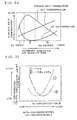
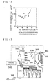
- Fig. 7 which is a characteristic diagram representing the relation between the NOx concentration and the air injection amount into the furnace chamber when the air injection amount into the furnace chamber increases, the NOx concentration climbs up.
- the water volume is controlled when the furnace exit temperature reaches a preset upper limit, it is impossible to control at a sufficient precision depending on slight combustion changes of refuse quality or the like.
- a method of manipulating the secondary combustion air quantity is understood. For example, as disclosed in Japanese Patent Application Laid-open No. 7-332642, by measuring the furnace exit temperature and oxygen concentration in the exhaust gas, and manipulating the secondary combustion air quantity so as to maintain the measurements at target values, complete combustion of refuse is further promoted to decrease the CO concentration in the exhaust gas.
- the conventional control method intended to decrease only the CO and other unburnt components in the exhaust gas by manipulating the secondary combustion air quantity
- the result of measurement of dioxins in the exhaust gas is obtained by analyzing the exhaust gas inspired for 4 hours. Therefore, if the combustion state in the furnace changes frequently, the inspiration of exhaust gas for 4 hours is a long time, and it is not known what point of combustion state change during inspiration of exhaust gas contributes most to generation of dioxins.
- the automatic combustion control device in such refuse incinerator is intended to control the secondary combustion air quantity, on the basis of reduction of CO concentration, one of harmful substances in the exhaust gas. More specifically, for complete combustion of unburnt components in the secondary combustion zone, by measuring the furnace exit temperature, and O 2 and CO concentrations in the exhaust gas by gas analyzers, the data are entered in the control device for used in feedback control, and the feed rate of the secondary combustion air is adjusted, and the temperature in the secondary combustion zone is kept high, so that an appropriate O 2 concentration is maintained.
- Fig. 43 shows an incinerator disclosed in Japanese Patent Application Laid-open No. 4-324015.
- an incinerator 330 is composed of a combustion chamber 331 and a secondary combustion chamber 332, in which primary combustion air is directly supplied into the combustion chamber 331 from beneath a fire grate 336 through a blower 335, and secondary combustion air is supplied into the secondary combustion chamber 332 through a nozzle 338 from a blower 337.
- CO detecting means (CO densitometer) 333 is provided in the secondary combustion chamber 332 at the entrance of a flue 334, and an output from the CO detecting means 333 is entered in a control device 340, and according to the result of measurement, excessive or insufficient amount of secondary combustion air quantity is calculated in order to obtain O 2 amount necessary for complete combustion in the secondary combustion chamber 332, and the secondary combustion air quantity rate and blowing temperature are controlled accordingly.
- the combustion state can be estimated only from one aspect. For example, when judged from the CO densitometer or heat image, it is hard to judge whether CO generation is caused by lack of oxygen, or temperature drop due to excessive oxygen.
- the correlation between CO concentration and dioxins is not favorable where the CO concentration is in a low concentration region of 50 ppm or less, and therefore the concentration of dioxins cannot be decreased strictly. Therefore, for the purpose of suppressing generation of dioxins, it is not recommended to use the CO concentration as a substitute index.
- the present invention employs the following constitutions.
- the main flue temperature of the incinerator, or the main flue temperature and at least one of O 2 concentration in exhaust gas, CO concentration in exhaust gas, and pressure difference above and beneath the post-incineration grate are measured, each measurement is periodically compared with each reference, and on the basis of the result of this comparison, the post-incineration air quantity which is the air quantity into the post-incineration grate, or the post-incineration air quantity and the moving speed of the post-incineration grate which determines the transfer amount of refuse are controlled.
- the generated combustion gas is mixed with part of secondary air, and is guided into a mixing chamber through a principal flue. Therefore, the main flue temperature varies with the combustion state above the post-incineration grate. Accordingly, by measuring the main flue temperature and comparing with the reference value, the combustion state of refuse on the post-incineration grate can be known. By controlling the post-incineration air quantity on the basis of the known combustion state, the refuse can be completely turned to ashes on the post-incineration grate, and generation of unburnt component is suppressed.
- O 2 concentration and CO concentration in exhaust gas vary with the combustion state of refuse on the post-incineration grate, and the pressure difference above and beneath the post-incineration grate varies with the refuse amount on the post-incineration grate.
- Other elements to be controlled aside from the post-incineration air quantity include the moving speed of the post-incineration grate which determines the transfer amount of refuse.
- the combustion state of refuse also varies with the amount of charged refuse, aside from the air quantity. Accordingly, when the refuse amount is adjusted by controlling the moving speed of the post-incineration grate, as well as controlling the post-incineration air quantity, the combustion state of refuse can be adjusted more promptly and appropriately.
- the combustion state of refuse on the post-incineration grate can be always monitored, and a slightest change having possibility of leading to abnormal state can be detected, and the speed of the post-incineration grate can be adjusted in advance.
- the speed of the post-incineration grate can be adjusted in advance.
- the shorter the period of measurement the higher is the control frequency, so that a sensible control is realized.
- the main flue temperature of the incinerator is measured, and the post-incineration air quantity is decreased when the main flue temperature does not reach the reference temperature, and the post-incineration air quantity is increased when the main flue temperature exceeds the reference temperature, thereby suppressing generation of unburnt component in the exhaust gas in the refuse incinerator.
- Deposits on the post-incineration grate are mostly ashes, but, in particular, when the unburnt refuse suddenly decreases to transfer to an excessive ash-abundant state, the post-incineration air quantity becomes excessive for the amount of refuse.
- deposits on the post-incineration grate deposits are cooled and the temperature is insufficient, and ignition of unburnt refuse is not promoted steadily to fall in an incomplete combustion state. In this state, the main flue temperature is lower than usual.
- the low temperature state on the post-incineration grate is detected.
- the unburnt refuse is in incomplete combustion state and that unburnt components are generated.
- the main flue temperature was temporarily lowered in less than two hours after start of measurement, and immediately before and after the fourth hour, and corresponding to these changes, the CO concentration in exhaust gas was temporarily raised. That is, when the main flue temperature is lower than usual, unburnt components are generated. It means an incomplete combustion state occurs when temperature is insufficient, out of three elements necessary for combustion, while unburnt refuse is present on the post-incineration grate and post-incineration air is blown in at reference level.
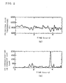
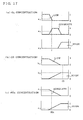
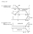
- Fig. 3 The incomplete combustion state caused by excessive post-incineration air is shown in Fig. 3.
- time-course changes of post-incineration air are shown in (a), and CO concentration in exhaust gas measurement at the same time are shown in (b).
- the post-incineration air quantity increased upon start of measurement, and about 0.8 hour and 2.7 hours after start of measurement, and the CO concentration in exhaust gas elevated corresponding to these changes. That is, when the post-incineration air quantity is increased excessively, the CO concentration in exhaust gas is heightened, and this state is eliminated when the excessive state of post-incineration air quantity is swept away.
- the main flue temperature is lowered when the post-incineration air quantity is excessive for the amount of unburnt refuse on the post-incineration grate, and at this time, the temperature is insufficient on the post-incineration grate, and unburnt components are generated. That is, when the main flue temperature is lower than the reference temperature, the post-incineration air quantity is excessive for the amount of unburnt refuse on the post-incineration grate, and hence the temperature is insufficient on the post-incineration grate, and unburnt components are generated. Therefore, when the main flue temperature is lower than the reference temperature, by decreasing the post-incineration air quantity, temperature drop is prevented to return to normal combustion, so that generation of unburnt components can be decreased.
- the post-incineration air quantity is insufficient for the amount of refuse on the post-incineration grate, and hence, on the post-incineration grate, oxygen is insufficient out of the three elements necessary for combustion, and unburnt components are generated.
- the main flue temperature of the incinerator and O 2 concentration in the exhaust gas are measured, and the post-incineration air quantity is decreased when the main flue temperature does not reach the reference temperature and the O 2 concentration in the exhaust gas exceeds the reference, and the post-incineration air quantity is increased when the main flue temperature exceeds the reference temperature and the O 2 concentration does not reach the reference, thereby suppressing the unburnt components in the exhaust gas in the refuse incinerator.
- post-incineration air quantity is excessive for the amount of unburnt refuse on the post-incineration grate, and hence temperature is insufficient on the post-incineration grate, and unburnt components are generated. Accordingly, by high O 2 concentration in exhaust gas, it is confirmed that the post-incineration air quantity is excessive for the amount of unburned refuse on the post-incineration grate. This is because if the post-incineration air quantity is excessive, unreacted O 2 is much contained in the combustion gas, and the O 2 concentration in exhaust gas is higher.
- the post-incineration air quantity is insufficient for the amount of refuse on the post-incineration grate, and hence oxygen is insufficient on the post-incineration grate, and unburnt components are generated.
- the post-incineration air quantity is insufficient for the amount of unburnt refuse on the post-incineration grate. It is because, when the post-incineration air quantity is insufficient, unreacted O 2 is not present, and the O 2 concentration in exhaust gas declines.
- the main flue temperature of the incinerator and CO concentration in the exhaust gas are measured, and the post-incineration air quantity is decreased when the main flue temperature does not reach the reference temperature and the CO concentration exceeds the reference, and the post-incineration air quantity is increased when the main flue temperature exceeds the reference temperature and the CO concentration exceeds the reference, thereby suppressing unburnt components in the exhaust gas in the refuse incinerator.
- CO represents the unburnt components
- This CO is an unburnt CO, not oxidized to CO 2 when the post-incineration air quantity is excessive for the amount of unburnt refuse on the post-incineration grate and the temperature is insufficient.
- the post-incineration air quantity is insufficient for the amount of unburnt refuse on the post-incineration grate, and hence oxygen is insufficient on the post-incineration grate, and unburnt components are generated.
- the difference between the pressure beneath the post-incineration grate and the furnace internal pressure is the pressure difference above and beneath the post-incineration grate, and it varies with the amount of deposits on the post-incineration grate.
- the pressure in the furnace is measured by a pressure gauge installed above the grate, and is always controlled at negative pressure. Comparing this furnace internal pressure and the pressure beneath the post-incineration grate, it is understood that post-incineration air is blown in beneath the post-incineration grate, and the pressure beneath the post-incineration grate is higher than the furnace internal pressure, and the difference between the pressure beneath the post-incineration grate and the furnace internal pressure (hereinafter called the pressure difference for short) is larger when the air stream resistance of deposits is larger. That is, when the pressure difference is small, the majority of deposits on the post-incineration grate is ash and the volume is small, or when the pressure difference is large, the majority of deposits is unburnt refuse, and the volume is large.
- the speed of the post-incineration grate can be controlled appropriately in addition to the control of the post-incineration air quantity. For example, when the refuse amount is excessive, by decreasing the speed of the post-incineration grate, while increasing the post-incineration air quantity, the amount of unburnt refuse decreases gradually, and it is burned down completely while taking time.
- the main flue temperature of the incinerator, and the difference between the pressure beneath the post-incineration grate and the furnace internal pressure are measured, and the post-incineration air quantity is decreased and the speed of the post-incineration grate is increased when the main flue temperature does not reach the reference temperature and the difference between the pressure beneath the post-incineration grate and the furnace internal pressure does not reach the reference difference, while the post-incineration air quantity is increased and the speed of the post-incineration grate is decreased when the main flue temperature exceeds the reference temperature and the difference between the pressure beneath the post-incineration grate and the furnace internal pressure exceeds the reference difference, thereby suppressing unburnt components in the exhaust gas in the refuse incinerator.
- the post-incineration air quantity is excessive for the amount of unburnt refuse on the post-incineration grate, and the temperature on the post-incineration grate is insufficient, and unburnt components are generated.
- the small pressure difference it is understood that the majority of deposits on the post-incineration grate is ashes, and that the amount of unburnt refuse is small.
- the post-incineration air quantity is insufficient for the amount of unburnt refuse on the post-incineration grate, and hence oxygen is insufficient on the post-incineration grate, and unburnt components are generated.
- the pressure difference is large, much unburnt refuse is contained in the deposits on the post-incineration grate.
- the main flue temperature of the incinerator, the O 2 concentration in the exhaust gas, and the difference between the pressure beneath the post-incineration grate and the furnace internal pressure are measured, and the post-incineration air quantity is decreased and the speed of the post-incineration grate is increased when the main flue temperature does not reach the reference temperature, the O 2 concentration exceeds the reference, and the difference between the pressure beneath the post-incineration grate and the furnace internal pressure does not reach the reference difference, while the post-incineration air quantity is increased and the speed of the post-incineration grate is decreased when the main flue temperature exceeds the reference temperature, the O 2 concentration does not reach the reference, and the difference between the pressure beneath the post-incineration grate and the furnace internal pressure exceeds the upper limit of the reference difference, thereby suppressing the unburnt components in the exhaust gas in the refuse incinerator.
- the main flue temperature of the incinerator, the CO concentration in the exhaust gas, and the difference between the pressure beneath the post-incineration grate and the furnace internal pressure are measured, and the post-incineration air quantity is decreased and the speed of the post-incineration grate is increased when the main flue temperature does not reach the reference temperature, the CO concentration exceeds the reference, and the difference between the pressure beneath the post-incineration grate and the furnace internal pressure does not reach the reference difference, while the post-incineration air quantity is increased and the speed of the post-incineration grate is decreased when the main flue temperature exceeds the reference temperature, the CO concentration exceeds the reference, and the difference between the pressure beneath the post-incineration grate and the furnace internal pressure exceeds the reference difference, thereby suppressing the unburnt components in the exhaust gas in the refuse incinerator.
- the speed of the post-incineration grate can be controlled also by, without determining the pressure difference, measuring the main flue temperature or main flue temperature and O 2 concentration or CO concentration in exhaust gas, and controlling the post-incineration air quantity, and controlling the speed of the post-incineration grate.
- the furnace exit temperature is measured periodically by a thermometer installed at the furnace exit
- the NOx concentration and CO concentration in the exhaust gas is measured periodically by an exhaust gas analyzer installed in the flue
- each measurement is compared with the reference, the on the basis of the result of comparison, the flow rate is controlled to spray water toward the combustion chamber burning the refuse on the grate in the furnace.
- the exhaust gas generated by burning refuse on the grate is branched off by the barrier installed in the furnace. Branched flows of exhaust gas are converged at the furnace exit, and are mixed by collision and agitation at this time, so that the unburnt components in the exhaust gas are burned again. Since the exhaust gas is agitated and mixed by the barrier, it is not necessary to mix the exhaust gas by spraying water, so that lowering of the furnace exit temperature can be prevented. Since the furnace exit temperature, NOx concentration and CO concentration represent the combustion state, by comparing the measured values of the furnace exit temperature, NOx concentration and CO concentration with the preset reference values, the water spray amount can be controlled depending on the changes in the combustion state. By measuring periodically, the combustion state is always monitored, and hence it is possible to cope with changes in the combustion state adequately. The shorter the interval of measurements, the higher is the frequency of control, so that very fine control is realized.
- the flow rate is controlled by decreasing the water spray amount when the measurement of the furnace exit temperature is lower than the reference or the measurement of CO concentration is higher than the reference, or increasing the water spray amount when the measurement of the furnace exit temperature is higher than the reference, or when the measurement of the furnace exit temperature is higher than the reference and the measurement of the NOx concentration is higher than the reference.
- the higher the furnace exit temperature the higher is the refuse combustion temperature, so that the NOx concentration is higher. Therefore, the temperature region for decreasing both CO and NOx simultaneously is understood to be present around 800°C.
- the more the water spray amount the lower is the furnace exit temperature because the furnace is cooled. Therefore, if the furnace exit temperature is over the reference value, or the furnace exit temperature is over the reference value and the NOx concentration exceeds the reference value, by increasing the water spray amount, the furnace exit temperature is lowered and the NOx concentration can be decreased.
- the furnace exit temperature is lower than the reference value, or when the CO concentration is higher the reference value, by decreasing the water spray amount, the furnace exit temperature is higher, and secondary combustion of unburnt components in exhaust gas is promoted, and it is understood that the CO concentration can be lowered.
- the flow rate is controlled, according to a fuzzy theory, by decreasing the water spray amount when the measurement of the furnace exit temperature is low, or when the measurement of the CO concentration is high, or increasing the water spray amount when the measurement of the furnace exit temperature is high, or when the measurement of the furnace exit temperature is high and the measurement of the NOx concentration is high.
- the fuzzy control is most suited as the control method for determining the operation output from the plural measurement inputs for calculating the increment or decrement of water spray by comprehensively judging the measured values of the furnace exit temperature, NOx concentration and CO concentration varying with the combustion state of refuse in the furnace, and the combustion state is appropriately controlled, and NOx in the exhaust gas is suppressed.
- the furnace exit temperature is measured periodically by the thermometer installed at the furnace exit
- the NOx concentration in exhaust gas is measured periodically by an exhaust gas analyzer installed in the flue, and each measurement is compared with the reference, and on the basis of the result of comparison, the flow rate is controlled for spraying water toward the combustion chamber burning the refuse on the fire grate in the furnace.
- the exhaust gas generated by burning refuse on the grate is branched off by the barrier installed in the furnace, and converged at the furnace exit to be mixed by collision and agitation, so that the unburnt components in the exhaust gas are burned again. Since the exhaust gas is agitated and mixed by the barrier, it is not necessary to mix the gas by spraying water, so that lowering of the furnace exit temperature can be prevented. Since the furnace exit temperature and NOx concentration represent the combustion state, by comparing the periodically measured values of the furnace exit temperature, NOx concentration with the preset reference values, the water spray amount can be controlled depending on the changes in the combustion state. By measuring periodically, the combustion state is always monitored, and hence it is possible to cope with changes in the combustion state adequately. The shorter the interval of measurements, the higher is the frequency of control, so that very fine control is realized.
- the flow rate is controlled by decreasing the water spray amount when the measurement of the furnace exit temperature is lower than the reference, or increasing the water spray amount when the measurement of the furnace exit temperature is higher than the reference, or when the measurement of the furnace exit temperature is higher than the reference and the measurement of the NOx concentration is higher than the reference.
- Fig. 9 is a characteristic diagram showing time-course changes of furnace exit temperature and CO concentration.
- the furnace exit temperature is lower than 800°C
- high CO concentration of about scores of to 100 ppm is generated.
- the water spray amount to operate so that the furnace exit temperature is maintained at 800°C or higher to promote secondary combustion of unburnt components in exhaust gas
- the CO concentration can be lowered.
- the CO concentration can be lowered without measuring the CO concentration.
- the flow rate is controlled, according to a fuzzy theory, by decreasing the water spray amount when the measurement of the furnace exit temperature is low, or increasing the water spray amount when the measurement of the furnace exit temperature is high, or when the measurement of the furnace exit temperature is high and the measurement of the NOx concentration is high.
- the fuzzy control is most suited as the control method for determining the operation output from the plural measurement inputs for calculating the increment or decrement of water spray by comprehensively judging the measured values of the furnace exit temperature and NOx concentration varying with the combustion state of refuse in the furnace, and the combustion state is appropriately controlled, and NOx in the exhaust gas is suppressed.
- O 2 concentration, NOx concentration and CO concentration in exhaust gas are periodically measured by exhaust gas analyzers installed in the flue, each measurement and reference are compared, and on the basis of the result of comparison, the flow rate is controlled for spraying water toward the combustion chamber burning refuse on the grate in the furnace.
- the exhaust gas generated by burning refuse on the grate is branched off by the partition wall installed in the furnace. Branched flows of exhaust gas are converged at the furnace exit, and are mixed by collision and agitation at this time, so that the unburnt components in the exhaust gas are burned again. Since the exhaust gas is agitated and mixed by the partition wall, it is not necessary to mix the exhaust gas by spraying water, so that lowering of the furnace exit temperature can be prevented.
- the flow rate of water spray is controlled by using the measured values of the furnace exit temperature, NOx concentration and CO concentration. In the relation of the furnace exit temperature and O 2 concentration in exhaust gas as shown in Fig.
- the combustion is active, and hence the furnace exit temperature is high. Therefore, using O 2 concentration instead of furnace exit temperature, by comparing the measured values of the O 2 concentration, NOx concentration and CO concentration with the preset reference values, the water spray amount can be controlled depending on the changes in the combustion state. By measuring periodically, the combustion state is always monitored, and hence it is possible to cope with changes in the combustion state adequately. The shorter the interval of measurements, the higher is the frequency of control, so that very fine control is realized.
- the flow rate is controlled by decreasing the water spray amount when the measurement of the O 2 concentration is higher than the reference or the measurement of CO concentration is higher than the reference, or increasing the water spray amount when the measurement of the O 2 concentration is lower than the reference, or when the measurement of the O 2 concentration is lower than the reference and the measurement of the NOx concentration is higher than the reference.
- the higher the furnace exit temperature the higher is the refuse combustion temperature, so that the NOx concentration is higher.
- the larger the water spray amount the more is suppressed combustion and the furnace is cooled, so that the furnace exit temperature is lower, and therefore, as shown in Fig. 15, the O 2 concentration becomes higher.
- the O 2 concentration is higher the reference value, or the CO concentration is higher than the reference value, by decreasing the water spray amount, the secondary combustion of unburnt components in exhaust gas is promoted, and the O 2 concentration is lowered, and the furnace exit temperature is raised, so that the CO concentration can be lowered.
- the O 2 concentration is lower than the reference, or the O 2 concentration is lower than the reference and the NOx concentration is higher tan the reference, by increasing the water spray amount, combustion is suppressed, and the furnace exit temperature is lowered, so that NOx concentration can be decreased.
- the flow rate is controlled according to a fuzzy theory by decreasing the water spray amount when the measurement of O 2 concentration is high or measurement of CO concentration is high, or increasing the water spray amount when the measurement of O 2 concentration is low or when the measurement of O 2 concentration is low and measurement of NOx concentration is high.
- the fuzzy control is most suited as the control method for determining the operation output from the plural measurement inputs for calculating the increment or decrement of water spray by comprehensively judging the measured values of the O 2 concentration, NOx concentration and CO concentration varying with the combustion state of refuse in the furnace, and the combustion state is appropriately controlled, and NOx in the exhaust gas is suppressed.
- the O 2 concentration and NOx concentration in the exhaust gas are periodically measured individually by exhaust gas analyzers installed in the flue, the measurement is compared with each reference, and on the basis of the result of comparison, the flow rate of the water spray toward the combustion chamber burning refuse on the grate in the furnace is controlled.
- the exhaust gas generated by burning refuse on the grate is branched off by the barrier installed in the furnace. Branched flows of exhaust gas are converged at the furnace exit, and are mixed by collision and agitation at this time, so that the unburnt components in the exhaust gas are burned again. Since the exhaust gas is agitated and mixed by the barrier, it is not necessary to mix the exhaust gas by spraying water, so that lowering of the furnace exit temperature can be prevented.
- the flow rate of water spray is controlled by using the measured values of the furnace exit temperature and NOx concentration. In the relation of the furnace exit temperature and O 2 concentration in exhaust gas as shown in Fig.
- the flow rate is controlled by decreasing the water spray amount when the measurement of the O 2 concentration is higher than the reference, or increasing the water spray amount when the measurement of the O 2 concentration is lower than the reference, or when the measurement of the O 2 concentration is lower than the reference and the measurement of the NOx concentration is higher than the reference.
- the higher the furnace exit temperature the higher is the refuse combustion temperature, so that the NOx concentration is higher.
- the larger the water spray amount the more is suppressed combustion and the furnace is cooled, so that the furnace exit temperature is lower, and therefore, as shown in Fig. 15, the O 2 concentration becomes higher.
- the O 2 concentration is higher the reference value, by decreasing the water spray amount, the O 2 concentration is lowered and the furnace exit temperature rises, so that the secondary combustion of unbumt components in exhaust gas is promoted, and the CO concentration can be lowered. If the O 2 concentration is lower than the reference, or the O 2 concentration is lower than the reference and the NOx concentration is higher than the reference, by increasing the water spray amount, combustion is suppressed, and the furnace exit temperature is lowered, so that NOx concentration can be decreased.
- the flow rate is controlled according to a fuzzy theory by decreasing the water spray amount when the measurement of O 2 concentration is high, or increasing the water spray amount when the measurement of O 2 concentration is low or when the measurement of O 2 concentration is low and measurement of NOx concentration is high.
- the fuzzy control is most suited as the control method for determining the operation output from the plural measurement inputs for calculating the increment or decrement of water spray by comprehensively judging the measured values of the O 2 concentration and NOx concentration varying with the combustion state of refuse in the furnace, and the combustion state is appropriately controlled, and NOx in the exhaust gas is suppressed.
- the furnace exit temperature or O 2 concentration is stabilized, and the CO concentration and NOx concentration in combustion exhaust gas are suppressed. Hence, generation of dioxins and other harmful components in combustion exhaust gas is suppressed, and refuse energy can be utilized efficiently by complete combustion.
- the furnace exit temperature is measured periodically by a thermometer installed in the furnace exit
- NOx concentration, CO concentration and O 2 concentration in exhaust gas are measured periodically by exhaust gas analyzers installed in the flue
- exhaust gas analyzers installed in the flue
- measurements of furnace exit temperature and NOx concentration are compared with each reference, and on the basis of the result of the comparison, the water spray amount to be sprayed toward the refuse burning on the grate is adjusted, and moreover the measurements of furnace exit temperature, NOx concentration, CO concentration and O 2 concentration are compared with each reference, and on the basis of the result of the comparison, the secondary combustion air quantity to be injected toward the combustion chamber is adjusted.
- the NOx generation in exhaust gas can be suppressed.
- the furnace exit temperature declines, and the CO concentration elevates. Therefore, by comparing the periodically measured values of furnace exit temperature and NOx concentration with the reference values of furnace exit temperature and NOx concentration, and adjusting the water spray amount so that the furnace exit temperature may maintain the reference, the generation of NOx and CO is suppressed.
- the furnace exit temperature is highest in the shaded area, in which the secondary combustion is very active and hence the CO concentration is low.
- the secondary combustion air quantity is small, and oxygen necessary for secondary combustion is insufficient, and, in oxygen deficiency state, secondary combustion is not executed, the CO concentration hikes, and the furnace exit temperature declines.
- the secondary combustion air quantity is enough, the furnace is cooled, the furnace exit temperature drops, and combustion is incomplete in spite of enough oxygen for secondary combustion, and thereby the CO concentration hikes.
- the NOx concentration becomes high in proportion to the secondary combustion air. Accordingly, by maintaining the operation of the secondary combustion air within the shaded area, both NOx concentration and CO concentration can be kept in low state.
- the rate of the measurement of CO concentration exceeding the target CO concentration per unit time is limited under the target CO generation rate.
- the behavior of CO concentration when the combustion state in the furnace is impaired is generally as shown in fig. 23, which is a characteristic diagram showing time-course changes of furnace exit temperature and others, and high concentrations of spike profile appear for several minutes to scores of minutes.
- the spike profile portion of this CO concentration is calculated as the rate of generation per unit time during measurement of dioxin concentration (4 hours), and the relation with the bag filter inlet dioxin concentration is investigated, it is understood to correspond to characteristic diagram (1) of bag filter inlet dioxin concentration in Fig. 25.
- the combustion state shown in the characteristic diagram in Fig. 24 corresponds to characteristic diagram (2) in Fig. 25.
- the higher the rate of generation of spikes of CO concentration the higher is the dioxin concentration. While spike CO is generated, the combustion is incomplete, and dioxin is discharged without being decomposed.
- spike CO is not generated during operation.
- a twenty-fourth aspect of the present invention relating to the twenty-first aspect, it is operated to keep the average of the measurements of the furnace exit temperature within a range of target lower limit average and target upper limit average.
- the water spray amount and secondary combustion air quantity by the twenty-first aspect so as to operate to maintain the average of the furnace exit temperature within the target lower limit average and target upper limit average, it is operate to maintain the average of the furnace exit temperature above the target lower limit average and below the target upper limit average.
- a twenty-sixth aspect of the present invention relating to the twenty-first aspect, it is operated to keep the rate of the measurement of CO concentration exceeding the target CO concentration per unit time under the target CO generation rate, the measurement of the furnace exit temperature above the target lower limit temperature, and the average of the measurements of the furnace exit temperature within a range of target lower limit average and target upper limit average.
- the target CO concentration is 30 ppm
- the target CO generation rate is 2%.
- the dioxin concentration can be effectively decreased.
- the target lower limit temperature is about 850°C. As shown in the characteristic diagram in Fig. 26, by setting the target lower limit temperature at about 850°C, the dioxin concentration can be effectively decreased.
- the target lower limit average is about 900°C
- the target upper limit average is about 950°C.
- the dioxin concentration and NOx concentration in exhaust gas can be effectively decreased.
- the water spray amount and secondary combustion air quantity are controlled according to a fuzzy theory.
- the parameter for setting the antecedent condition for estimating the water spray amount and the shape of the antecedent membership function, and the parameter for setting the antecedent condition for estimating the secondary combustion air quantity and the shape of the antecedent membership function are different from each other.
- NOx and unburnt components are suppressed by adjusting the secondary combustion air quantity. If the furnace exit temperature is a large value exceeding the specified reference, the water spray amount is also adjusted in addition to the secondary combustion air quantity, so that elevation of NOx and furnace exit temperature is suppressed.
- the furnace exit temperature is stabilized and the NOx concentration is controlled at a specified value, or the furnace exit temperature and O 2 concentration are stabilized and CO concentration and NOx concentration are controlled at specified values respectively. Accordingly, generation of NOx and unburnt components is suppressed, and generation of dioxins and other harmful components can be suppressed.
- chlorobenzenes and chlorophenols in exhaust gas if their concentration is in low concentration region (50 ppm or less), have a correlative relation with concentration of dioxins, and are hence handled as precursors of dioxins, and they are hardly lost by removal of moisture in the pretreatment of exhaust gas and are hence used as useful substitute index substances, and therefore the secondary combustion air quantity is controlled by using control parameters in combustion control of refuse incinerator.
- it is a combustion control method of controlling the primary combustion air quantity so as to stabilize the steam generation amount generated from a boiler installed in the refuse incinerator, and controlling the secondary combustion air quantity for refiring, in which generation of NOx in exhaust gas is suppressed by controlling the secondary combustion air quantity by control parameters, that is, the steam generation amount, the secondary combustion air quantity, furnace exit temperature, and CO concentration, O 2 concentration and NOx concentration in exhaust gas, and the O 2 concentration for minimizing the concentration of precursors of dioxins is estimated from the mutual relation of the concentration of precursors of dioxins and O 2 concentration in the exhaust gas, and thereby the secondary combustion air quantity is adjusted, and generation of dioxins in exhaust gas is suppressed.
- control parameters that is, the steam generation amount, the secondary combustion air quantity, furnace exit temperature, and CO concentration, O 2 concentration and NOx concentration in exhaust gas, and the O 2 concentration for minimizing the concentration of precursors of dioxins is estimated from the mutual relation of the concentration of precursors of dioxins and O 2 concentration in the exhaust
- the CO concentration and NOx concentration in exhaust gas in the incinerator are decreased, the concentration of precursors of dioxins in exhaust gas generated from the incinerator is detected, and the control parameters are corrected according to the O 2 concentration for minimizing the precursors of dioxins, and the secondary combustion air quantity is controlled.
- the precursors of dioxins are chlorobenzenes and chlorophenols in exhaust gas, and from the mutual relation of the sum of these concentration values and O 2 concentration in exhaust gas, the O 2 concentration for minimizing the sum of the concentration of the chlorobenzenes and chlorophenols is estimated.
- the secondary combustion air quantity is controlled while correcting the control parameters by the O 2 concentration for minimizing the concentration of the precursors of dioxins obtained from the mutual relation of the sum of their concentrations and O 2 concentration.
- generation of NOx in exhaust gas is suppressed by calculating the secondary combustion air quantity by nonlinear control
- the concentration of precursors of dioxins, that is, chlorobenzenes and chlorophenols is measured by exhaust gas analyzers of continuous or semicontinuous analyzers, the mutual relation of the sum of these concentrations and the O 2 concentration is calculated periodically by a function approximating method, the O 2 concentration for minimizing the concentration of chlorobenzenes and chlorophenols is calculated, the control parameter of O 2 concentration is sequentially corrected, and the secondary combustion air quantity is adjusted by executing the nonlinear control.
- the combustion state in the furnace is judged, and by calculating and adjusting the secondary combustion air quantity, generation of CO and NOx in exhaust gas is suppressed.
- the concentration of chlorobenzenes and chlorophenols in exhaust gas is detected, and the O 2 concentration for minimizing the sum of these values is estimated and the control parameters of O 2 concentration are corrected sequentially to execute the nonlinear control, and therefore generation of dioxins is suppressed while coping with changes on concentrations of chlorobenzenes, chlorophenols and O 2 .
- the nonlinear control is fuzzy control.
- the control rules can be verbally described, adjustment of parameters is easy, and by applying the fuzzy control, the secondary combustion can be controlled finely.
- the combustion control apparatus of refuse incinerator comprises primary combustion control means for feeding primary combustion air into the refuse incinerator to burn the combustible in the furnace, and controlling to stabilize the boiler steam generation amount, secondary combustion air control means for feeding secondary combustion air into the refuse incinerator for refiring the unburnt component, O 2 concentration measuring means for detecting the O 2 concentration in exhaust gas, exhaust gas analyzing means for measuring the concentration of precursors of dioxins in exhaust gas, correlative curve estimating means for calculating the mutual relation between the concentration of precursors of dioxins detected by the exhaust gas analyzing means and the O 2 concentration detected by the O 2 concentration measuring means, and operating means for calculating the O 2 concentration for minimizing the sum of the concentration of precursors of dioxins from the mutual relation determined by the correlative curve estimating means, in which the secondary combustion air quantity is calculated by the secondary combustion control means by making use of control parameters on the basis of the O 2 concentration calculated by the operating means, and the
- the correlative curve estimating means generation of dioxins is suppressed by calculating the O 2 concentration for minimizing the concentration of dioxins from the mutual relation of the concentration of precursors of dioxins and O 2 concentration, and correcting the control parameters for operating and processing the secondary combustion air control means on the basis of this value.
- the multiple-variable control can be automated.
- the precursors of dioxins are chlorobenzenes and chlorophenols.
- chlorobenzenes and chlorophenols are very low in concentration, they have a correlation with O 2 concentration, and hence by measuring the concentration of chlorobenzenes and chlorophenols, generation of dioxins can be suppressed by estimating the O 2 concentration for minimizing the concentration of dioxins.
- the combustion control apparatus of refuse incinerator comprises primary combustion air control means for feeding primary combustion air into the refuse incinerator to burn the combustible in the furnace, and controlling to stabilize the boiler steam generation amount, secondary combustion air control means for measuring periodically the boiler steam generation amount, secondary combustion air quantity, furnace exit temperature, and CO concentration, O 2 concentration and NOx concentration in exhaust gas analyzer, and controlling the secondary combustion air quantity on the basis of each measurement, a continuous or semicontinuous analyzer for measuring chlorobenzenes and chlorophenols in exhaust gas, correlative curve estimating means for determining the mutual relation on the basis of the sum of the measured chlorobenzenes and chlorophenols by the continuous or semicontinuous analyzer and the measurement of O 2 concentration, and operating means for calculating the O 2 concentration for minimizing the sum of the concentrations of chlorobenzenes and chlorophenols in exhaust gas from the mutual relation determined by the correlative curve estimating means, in which by sequentially correcting the
- the multiple-variable control can be automated.
- the secondary combustion control means is fuzzy control means.
- the control rules can be verbally described, adjustment of parameters is easy, and by applying the fuzzy control means, the secondary combustion control amount can be controlled finely.
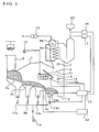
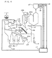
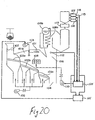
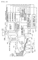
- Fig. 1 is a conceptual diagram of a refuse incinerator and its control system.
- Reference numeral 1 is an incinerator, and refuse charged from a refuse inlet 2 is sent in the sequence of a precombustion grate 3a, a combustion grate 3b, and a post-incineration grate 3c, and is burned into ashes and discharged from a chute 4.
- Each grate is driven by an individual grate drive device, and sends forward the refuse at a prescribed speed.
- a grate drive device 3d for the post-incineration grate 3c is shown.
- the primary air is distributed in an air damper 13 a beneath the precombustion grate for adjusting the air quantity of precombustion grate, an air damper 13b beneath the compression grate for adjusting the air quantity before the combustion grate, an air damper 13c beneath the combustion grate for adjusting the air quantity after the combustion grate, and an air damper 13d beneath the post-incineration grate for adjusting the air quantity of the post-incineration grate.
- the gas leaving the mixing chamber 6 passes through a heat exchanger 8a installed at the furnace exit, and is exhausted after energy is recovered.
- Reference numeral 7 is a furnace exit thermometer
- 8b is a boiler
- 12 is a flowmeter for measuring the steam amount
- 14 is a principal flue thermometer
- 16 is an exhaust gas O 2 densitometer
- 17 is an exhaust gas CO densitometer
- 18a is a furnace internal pressure gauge
- 18b is a pressure gauge beneath the post-incineration grate.
- Reference numeral 15 is a control device, which receives signals from the principal flue thermometer 14, exhaust gas O 2 densitometer 16, exhaust gas CO densitometer 17, furnace internal pressure gauge 18a, and pressure gauge 18b beneath the post-incineration grate, and issues control value signals to the air damper 13d beneath the post-incineration grate and the grate drive device 3d.
- a control device for example, a computer is used.
- control value is calculated periodically.
- the move of refuse on the grate is slow, and it takes scores of minutes to pass through the post-incineration grate, and hence it is appropriate to calculate in a period of scores of seconds to several minutes.
- the control value is calculated as follows.
- the control value F n of the post-incineration is calculated in formula (1).
- F n F n-1 + k T (T - T set ) where F n-1 is a previous control value, and KT is a control parameter about main flue temperature, which is positive.
- F n F n-1 + k T (T - T set ) + k O 2 ([O 2 ] - [O 2 ] set )
- k o 2 is a control parameter about O 2 concentration in exhaust gas, which is negative when the measurement T of main flue temperature is smaller than reference temperature T set and the measurement [O 2 ] of O 2 concentration in exhaust gas is larger than the reference [O 2 ] set , or when the measurement T of the main flue temperature is larger than the reference temperature value T set and the measurement [O 2 ] of the O 2 concentration in exhaust gas is smaller than the reference [O 2 ] set , and is zero otherwise.
- the control value F n of the post-incineration air quantity is calculated in formula (3).
- F n F n-1 + k T (T - T set ) + k CO ([CO] - [CO] set )
- k co is a control parameter about CO concentration in exhaust gas, which is negative when the measurement T of main flue temperature is smaller than reference temperature T set and the measurement [CO] of CO concentration in exhaust gas is larger than the reference [CO] set , positive when the measurement T of the main flue temperature is larger than the reference temperature value T set and the measurement [CO] of the CO concentration in exhaust gas is larger than the reference [CO] set , and is zero otherwise.
- the control value F n of the post-incineration air quantity is determined in formula (1), and the control value G n of the post-incineration grate speed is calculated in formula (3), supposing the pressure difference to be ⁇ P and reference difference to be ⁇ P set .
- G n G n-1 + h p ( ⁇ P - ⁇ P set ) where G n-1 is a previous control value, and h p is a control parameter about pressure difference, which is negative.
- the control value F n of the post-incineration air quantity is determined in formula (2), and the control value G n of the post-incineration grate speed is calculated in formula (4).
- the control value F n of the post-incineration air quantity is determined in formula (3), and the control value G n of the post-incineration grate speed is calculated in formula (4).
- the control value F n of post-incineration air quantity is determined in formula (3), and the control value G n of post-incineration grate speed is determined in formula (5).
- G n G n-1 + h T (T - T set ) + h CO ([CO] - [CO] set )
- h T is a control parameter about the main flue temperature, which is negative
- h co is a parameter about CO concentration in exhaust gas, which is positive when the measurement T of main flue temperature is smaller than reference T set and the measurement [CO] of CO concentration in exhaust gas is larger than the reference [CO] set , negative when the measurement T of the main flue temperature is larger than the reference temperature T set and the measurement [CO] of the CO concentration in exhaust gas is larger than the reference [CO] set , and is zero otherwise.
- the upper limit or lower limit may be used as the reference value, and when the measured value is in the limit range, the difference between the measured value and reference value may be calculated as zero.
- the O 2 concentration in exhaust gas may be measured simultaneously with the CO concentration, and these items may be added in calculation.
- measured values by measuring the secondary air quantity or primary air quantity beneath each grate, fluctuations of these air quantity may be detected, and the O 2 concentration and CO concentration may be corrected and applied.
- control method of the present invention may be combined with a method of measuring the furnace exit temperature or generated steam amount and controlling the secondary air quantity in order to keep them constant.
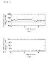
- the reference value T set of the main flue temperature was 850°C, and the operating period of control value was 1 minute.
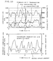
- the result is shown in Fig. 4 together with the measured values of the main flue temperature.
- (a) shows changes of main flue temperature, and (b) records the CO concentration in exhaust gas measured at the same time.
- the measurement lasted for 5 hours, but, on the post-incineration grate, since the combustion was controlled by control of post-incineration air quantity, the main flue temperature was controlled in a range of 820°C to 930°C, and the CO concentration in exhaust gas was suppressed under 20 ppm.
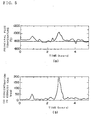
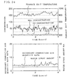
- Fig. 5 shows the conventional result corresponding to Fig. 4.
- the main flue temperature varies in a range of 750°C to 1050°C, and when the main flue temperature is high, the CO concentration in the exhaust gas is over 200 ppm.
- Fig. 6 is a conceptual diagram of a refuse incinerator for controlling NOx and unburnt components in exhaust gas in a refuse incinerator and its control system.
- a dust inlet (hopper) 102 is provided above a refuse incinerator 101, and the refuse charged through the refuse inlet 102 is sent sequentially into a precombustion grate 103a, a combustion grate 103b, and a post-incineration grate 103c installed in a combustion chamber 101a.
- Beneath the grates 103a, 103b, 103c primary combustion air for drying or firing supplied from a primary combustion air fan 105 is sent in.
- the refuse On the precombustion grate 103a, the refuse is mainly dried, on the combustion grate 103b, the refuse is burned, and on the pre-incineration grate 103c, it is completely burned to be ash.
- the ash drops from a chute 104, and is discharged from the furnace.
- This refuse incinerator comprises water spray amount control means 117, and this control means 117 receives signals of a furnace exit thermometer 112, an exhaust gas O 2 densitometer 114, an exhaust gas NOx densitometer 115, and an exhaust gas CO densitometer 116, generates control signals by operating specified calculation, and issues to the water spray amount regulator 113.
- the control means 117 for example, a computer is used. Control values on the basis of the input signals are calculated periodically in the control means 117. Fluctuations the furnace exit temperature and exhaust gas components due to changes in the water spray amount are in a range of scores of seconds to several minutes, and hence it is appropriate to calculate in a period of scores of seconds to several minutes.
- Table 1 is a table showing the concept of control method of water spray amount. As shown in Table 1, the water spray amount is calculated in the sequence of conditions (1) to (4), and when the conditions of (1) to (4) are satisfied, the control indicated by arrow ( ⁇ ) is executed. However, if all of conditions of (1) to (4) are not satisfied, the present water spray amount is maintained. A specific value for increasing or decreasing the water spray amount (the increment or decrement per period) can be set individually.
- T denotes the measured value of furnace exit temperature
- CO is the measured value of CO concentration
- NOx is the measured value of NOx concentration.
- T set1 is an adjustment parameter for judging if the furnace exit temperature is less than a specific value or not
- CO set is an adjustment parameter for judging if the CO concentration is over a specific value or not
- NOx set is an adjustment parameter for judging if the NOx concentration is over a specific value or not
- T set2 is an adjustment parameter for judging if the furnace exit temperature is over a specific value or not
- u1 to u4 are adjustment parameters for giving the increment or decrement of water spray amount.
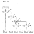
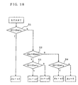
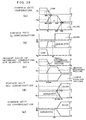
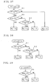
- step S 1 the furnace exit temperature (T) is judged by the control condition (T ⁇ T set1 ), and when the control condition (T ⁇ T set1 ) is satisfied, the adjustment amount du is set at adjustment parameter u 1 , and when the control condition (T ⁇ T set1 ) is not satisfied, the process advances to step S 2 .
- step S 2 the CO concentration (CO) is judged by the control condition (CO > CO set ), and when the control condition (CO > CO set ) is satisfied, the adjustment amount du is set at adjustment parameter u 2 , and when the control condition (CO > CO set ) is not satisfied, the process advances to step S 3 .
- the NOx concentration (NOx) is judged by the control condition (NOx > NOx set ), and when the control condition (NOx > NOx set ) is satisfied, the process advances to step S 4 , and when the control condition (NOx > NOx set ) is not satisfied, the process advances to step S 5 .
- the furnace exit temperature (T) is judged by the control condition (T > T set2 ), and when the control condition (T > T set2 ) is satisfied, the adjustment amount du is set at adjustment parameter u 3 , and when the control condition (T > T set2 ) is not satisfied, the adjustment amount du is set at adjustment parameter 0.
- the furnace exit temperature (T) is judged by the control condition (T > T set2 ), and when the control condition (T > T set2 ) is satisfied, the adjustment amount du is set at adjustment parameter u 4 , and when the control condition (T > T set2 ) is not satisfied, the adjustment amount du is set at adjustment parameter 0.
- the value of the water spray adjustment amount du calculated according to the process in the flowchart in Fig. 10 is put in formula (11), and the water spray amount output value (u K ) is calculated, and the opening degree of the flow rate regulating mechanism is adjusted according to the water spray amount output value (u K ).
- a control method of water spray amount is described below.
- Table 2 is a table showing fuzzy rules about execution of flow rate control by fuzzy control
- Table 3 summarizes rules (1) to (6) in Table 2. Fuzzy control method of water spray amount (1) When furnace exit temperature is low ⁇ decrease water spray amount. (2) When CO concentration is high ⁇ decrease water spray amount. (3) When furnace exit temperature is adequate ⁇ maintain present water spray amount. (4) When NOx concentration is adequate ⁇ maintain present water spray amount. (5) When furnace exit temperature is high ⁇ increase water spray amount.
- the antecedent (input) is the furnace exit temperature, CO concentration and NOx concentration, and the consequent (output) is the increment or decrement of water spray amount.
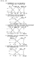
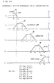
- Operation of each rule is based on the membership function shown in Fig 11.
- Operation of furnace exit temperature is based on the function shown in Fig. 11 (a), operation of CO concentration in Fig. 11 (b), and operation of NOx concentration in Fig. 11 (c).
- the increment or decrement of water spray amount is calculated. If the condition is not satisfied, however, its output is calculated as zero.
- the reasoning result of the entire rules is issued.
- a general fuzzy operation technique is used, such as mini-max center of gravity method or product-sum center of gravity method.
- the reasoning result obtained in the water spray amount control means 117 is issued to the flow rate regulating mechanism, and the water spray amount is adjusted.
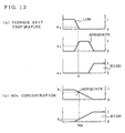
- Fig. 11 shows the antecedent membership function of the furnace exit temperature, and when the measured value of furnace exit temperature is T, the goodness of fit for the condition of "furnace exit temperature is low" is a 1 . For the condition of "furnace exit temperature is adequate,” the goodness of fit is a 2 . For the condition of "furnace exit temperature is high,” the goodness of fit is a 3 .
- Fig. 11 (b) shows the antecedent membership function of CO concentration, and when the measured value of CO is CO, the goodness of fit for the condition of "CO concentration is low" is b 1 . For the condition of "CO concentration is high,” the goodness of fit is b 2 .
- Fig. 11 (c) shows the antecedent membership function of NOx concentration, and when the measured value of NOx is NOx, the goodness of fit for the condition of "NOx concentration is adequate" is c 1 . For the condition of "NOx concentration is high,” the goodness of fit is c 2 .
- the goodness of fit X 1 for rule (1) in Table 3 is calculated in formula (12).
- a control method of water spray amount is described.
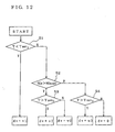
- the spray amount control means 117 in Fig. 6 a control method of water spray amount on the basis of the measured values of furnace exit temperature and NOx concentration is explained in the case of increment and decrement control by condition by referring to Table 4 and Fig. 12.
- rule (2) in Table 1 is omitted.
- Table 4 is a table showing the concept of control method of water spray amount. As shown in Table 4, the water spray amount is calculated in the sequence of conditions (1) to (3), and when the conditions of (1) to (3) are satisfied, the control indicated by arrow ( ⁇ ) is executed. However, if all of conditions of (1) to (3) are not satisfied, the present water spray amount is maintained. A specific value for increasing or decreasing the water spray amount (the increment or decrement per period) can be set individually. Control method of water spray amount (1) When furnace exit temperature is low (S 1 ) ⁇ decrease water spray amount by a specific amount. (2) When NOx concentration is high (S 2 ) and furnace exit temperature is also high (S 3 ) ⁇ increase water spray amount by a specific amount. (3) When furnace exit temperature is high (S 4 ) ⁇ increase water spray amount by a specific amount.
- T denotes the measured value of furnace exit temperature
- NOx is the measured value of NOx concentration.
- T set1 in Fig. 12 is an adjustment parameter for judging if the furnace exit temperature is less than a specific value or not
- CO set is an adjustment parameter for judging if the CO concentration is over a specific value or not
- NOx set is an adjustment parameter for judging if the NOx concentration is over a specific value or not
- T set2 is an adjustment parameter for judging if the furnace exit temperature is over a specific value or not
- v1 to v3 are adjustment parameters for giving the increment or decrement of water spray amount.
- step S 1 the furnace exit temperature (T) is judged by the control condition (T ⁇ T set1 ), and when the control condition (T ⁇ T set1 ) is satisfied, the adjustment amount dv is set at adjustment parameter v 1 , and when the control condition (T ⁇ T set1 ) is not satisfied, the process advances to step S 2 .
- step S 2 the NOx concentration (NOx) is judged by the control condition (NOx > NOx set ), and when the control condition (NOx > NOx set ) is satisfied, the process advances to step S3, and when the control condition (NOx > NOx set ) is not satisfied, the process advances to step S 4 .
- the furnace exit temperature (T) is judged by the control condition (T > T set2 ), and when the control condition (T > T set2 ) is satisfied, the adjustment amount dv is set at adjustment parameter v 2 , and when the control condition (T > T set2 ) is not satisfied, the adjustment amount dv is set at adjustment parameter 0.
- the furnace exit temperature (T) is judged by the control condition (T > T set2 ), and when the control condition (T > T set2 ) is satisfied, the adjustment amount dv is set at adjustment parameter v 3 , and when the control condition (T > T set2 ) is not satisfied, the adjustment amount dv is set at adjustment parameter 0.
- the value of the water spray adjustment amount dv calculated according to the process in the flowchart in Fig. 12 is put in formula (20), and the water spray amount output value (v k ) is calculated, and the opening degree of the flow rate regulating mechanism is adjusted according to the water spray amount output value (v k ).
- a control method of water spray amount is described below.
- this is to explain execution of control of water spray amount on the basis of measured values of furnace exit temperature and NOx concentration by fuzzy control.
- rule (2) in Table 2 is omitted.
- Table 5 is a table showing fuzzy rules about execution of flow rate control by fuzzy control, and Table 6 summarizes rules (1) to (5) in Table 5. Fuzzy control method of water spray amount (1) When furnace exit temperature is low ⁇ decrease water spray amount. (2) When furnace exit temperature is adequate ⁇ maintain present water spray amount. (3) When NOx concentration is adequate ⁇ maintain present water spray amount. (4) When furnace exit temperature is high ⁇ increase water spray amount. (5) When furnace exit temperature is high and NOx concentration is also high ⁇ increase water spray amount.
- the antecedent (input) is the furnace exit temperature and NOx concentration
- the consequent (output) is the increment or decrement of water spray amount. Operation of each rule is based on the membership function shown in Fig 13. Operation of furnace exit temperature is based on the function shown in Fig. 13 (a), and operation of NOx concentration in Fig. 13 (b).
- the increment or decrement of water spray amount is calculated. If the condition is not satisfied, however, its output is calculated as zero.
- the reasoning result of the entire rules is issued.
- a general fuzzy operation technique is used, such as mini-max center of gravity method or product-sum center of gravity method.
- the reasoning result obtained in the water spray amount control means 117 is issued to the flow rate regulating mechanism, and the water spray amount is adjusted.
- Fig. 13 shows the antecedent membership function of the furnace exit temperature, and when the measured value of furnace exit temperature is T, the goodness of fit for the condition of "furnace exit temperature is low" is a 1 . For the condition of "furnace exit temperature is adequate,” the goodness of fit is a 2 . For the condition of "furnace exit temperature is high,” the goodness of fit is a 3 .
- X 1 a 1 Goodness of fit of rule (2)
- X 2 a 2 Goodness of fit of rule (3)
- X 3 b 1 Goodness of fit of rule (4)
- X 4 a 3 Goodness of fit of rule (5)
- X 5 a 3 ⁇ b 2
- a control method of water spray amount is described.
- the water spray amount control means 117 in Fig. 6 a control method of water spray amount on the basis of the measured values of O 2 concentration, CO concentration and NOx concentration is explained in the case of increment and decrement control by condition by referring to Table 7 and Fig. 16.
- Table 7 is a table showing the concept of control method of water spray amount. As shown in Table 7, the water spray amount is calculated in the sequence of conditions (1) to (4), and when the conditions of (1) to (4) are satisfied, the control indicated by arrow ( ⁇ ) is executed. However, if all of conditions of (1) to (4) are not satisfied, the present water spray amount is maintained.
- a specific value for increasing or decreasing the water spray amount can be set individually.
- Control method of water spray amount (1) When O 2 concentration is high (S 1 ) ⁇ decrease water spray amount by a specific amount. (2) When CO concentration is high (S 2 ) ⁇ decrease water spray amount by a specific amount. (3) When NOx concentration is high (S 3 ) and O 2 concentration is also low (S 4 ) ⁇ increase water spray amount by a specific amount. (4) When O 2 concentration is low (S 5 ) ⁇ increase water spray amount by a specific amount.
- O 2 denotes the measured value of O 2 concentration
- CO is the measured value of CO concentration
- NOx is the measured value of NOx concentration
- O 2set1 is an adjustment parameter for judging if the O 2 concentration is over a specific value or not
- CO set is an adjustment parameter for judging if the CO concentration is over a specific value or not
- NOx set is an adjustment parameter for judging if the NOx concentration is over a specific value or not
- O 2set2 is an adjustment parameter for judging if the O 2 concentration is less than a specific value or not
- w1 to w4 are adjustment parameters for giving the increment or decrement of water spray amount.
- step S 1 the O 2 concentration (O 2 ) is judged by the control condition (O 2 > O 2set1 ), and when the control condition (O 2 > O 2set1 ) is satisfied, the adjustment amount dw is set at adjustment parameter w 1 , and when the control condition (O 2 > O 2set1 ) is not satisfied, the process advances to step S 2 .
- step S 2 the CO concentration (CO) is judged by the control condition (CO > CO set ), and when the control condition (CO > CO set ) is satisfied, the adjustment amount dw is set at adjustment parameter w2, and when the control condition (CO > CO set ) is not satisfied, the process advances to step S 3 .
- step S 3 the NOx concentration (NOx) is judged by the control condition (NOx > NOx set ), and when the control condition (NOx > NOx set ) is satisfied, the process advances to step S 4 , and when the control condition (NOx > NOx set ) is not satisfied, the process advances to step S 5 .
- step S 4 the O 2 concentration (O 2 ) is judged by the control condition (O 2 ⁇ O 2set2 ), and when the control condition (O 2 ⁇ O 2set2 ) is satisfied, the adjustment amount dw is set at adjustment parameter w3, and when the control condition (O 2 ⁇ O 2set2 ) is not satisfied, the adjustment amount dw is set at adjustment parameter 0.
- the O 2 concentration (O 2 ) is judged by the control condition (O 2 ⁇ O 2set2 ), and when the control condition (O 2 ⁇ O 2set2 ) is satisfied, the adjustment amount dw is set at adjustment parameter w4, and when the control condition (O 2 ⁇ O 2set2 ) is not satisfied, the adjustment amount dw is set at adjustment parameter 0.
- the value of the water spray adjustment amount dw calculated according to the process in the flowchart in Fig. 16 is put in formula (28), and the water spray amount output value (w k ) is calculated, and the opening degree of the flow rate regulating mechanism is adjusted according to the water spray amount output value (w k ).
- a control method of water spray amount is described below.
- this is to explain execution of control of water spray amount on the basis of measured values of O 2 concentration, CO concentration and NOx concentration by fuzzy control.
- Table 8 is a table showing fuzzy rules about execution of flow rate control by fuzzy control, and Table 9 summarizes rules (1) to (6) in Table 8. Fuzzy control method of water spray amount (1) When O 2 concentration is high ⁇ decrease water spray amount. (2) When CO concentration is high ⁇ decrease water spray amount. (3) When O 2 concentration is adequate ⁇ maintain present water spray amount. (4) When NOx concentration is adequate ⁇ maintain present water spray amount. (5) When O 2 concentration is low ⁇ increase water spray amount.
- the antecedent (input) is the O 2 concentration, CO concentration and NOx concentration
- the consequent (output) is the increment or decrement of water spray amount. Operation of each rule is based on the membership function shown in Fig 17. Operation of O 2 concentration is based on the function shown in Fig. 17 (a), operation of CO concentration in Fig. 17 (b), and operation of NOx concentration in Fig. 17 (c).
- the increment or decrement of water spray amount is calculated. If the condition is not satisfied, however, its output is calculated as zero.
- the water spray amount control means 117 In the water spray amount control means 117, integrating the consequent reasoning results of rules determined in the above operations, the reasoning result of the entire rules is issued. For integration of consequent reasoning results of rules, a general fuzzy operation technique is used, such as mini-max center of gravity method or product-sum center of gravity method. The reasoning result obtained in the water spray amount control means 117 is issued to the flow rate regulating mechanism, and the water spray amount is adjusted.
- Fig. 17 (a) shows the antecedent membership function of the O 2 concentration, and when the measured value of O 2 concentration is O 2 , the goodness of fit for the condition of "O 2 concentration is low" is a 1 . For the condition of "O 2 concentration is adequate,” the goodness of fit is a 2 . For the condition of "O 2 concentration is high,” the goodness of fit is a 3 .
- Fig. 17 (b) shows the antecedent membership function of CO concentration, and when the measured value of CO is CO, the goodness of fit for the condition of "CO concentration is low" is b 1 . For the condition of "CO concentration is high,” the goodness of fit is b 2 .
- Fig. 17 (c) shows the antecedent membership function of NOx concentration, and when the measured value of NOx is NOx, the goodness of fit for the condition of "NOx concentration is adequate" is c 1 . For the condition of "NOx concentration is high,” the goodness of fit is c 2.
- the goodness of fit X 1 for rule (1) in Table 9 is calculated in formula (30).
- X 1 a 3 Goodness of fit of rule (2)
- X 2 b 2 Goodness of fit of rule (3)
- X 3 a 2 Goodness of fit of rule (4)
- X 4 c 1 Goodness of fit of rule (5)
- X 5 a 1 Goodness of fit of rule (6)
- X 6 a 1 ⁇ C 2
- a control method of water spray amount is described.
- the spray amount control means a control method of water spray amount on the basis of the measured values of O 2 concentration and NOx concentration is explained in the case of increment and decrement control by condition by referring to Table 10 and Fig. 18.
- rule (2) in Table 7 is omitted.
- Table 10 is a table showing the concept of control method of water spray amount. As shown in Table 10, the water spray amount is calculated in the sequence of conditions (1) to (3), and when the conditions of (1) to (3) are satisfied, the control indicated by arrow ( ⁇ ) is executed. However, if all of conditions of (1) to (3) are not satisfied, the present water spray amount is maintained. A specific value for increasing or decreasing the water spray amount (the increment or decrement per period) can be set individually. Control method of water spray amount (1) When O 2 concentration is high (S 1 ) ⁇ decrease water spray amount by a specific amount. (2) When NOx concentration is high (S 2 ) and O 2 concentration is also low (S 3 ) ⁇ increase water spray amount by a specific amount. (3) When O 2 concentration is low (S 4 ) ⁇ increase water spray amount by a specific amount.
- O 2 denotes the measured value of O 2 concentration
- NOx is the measured value of NOx concentration
- O 2set1 is an adjustment parameter for judging if the O 2 concentration is over a specific value or not
- NOx set is an adjustment parameter for judging if the NOx concentration is over a specific value or not
- O 2Set2 is an adjustment parameter for judging if the O 2 concentration is less than a specific value or not
- x1 to x3 are adjustment parameters for giving the increment or decrement of water spray amount.
- step S 1 the O 2 concentration (O 2 ) is judged by the control condition (O 2 > O 2set1 ), and when the control condition (O 2 > O 2set1 ) is satisfied, the adjustment amount dx is set at adjustment parameter x 1 , and when the control condition (O 2 > O 2set1 ) is not satisfied, the process advances to step S 2 .
- step S 2 the NOx concentration (NOx) is judged by the control condition (NOx > NOx set ), and when the control condition (NOx > NOx set ) is satisfied, the process advances to step S 3 , and when the control condition (NOx > NOx set ) is not satisfied, the process advances to step S 4 .
- the O 2 concentration (O 2 ) is judged by the control condition (O 2 ⁇ O 2set2 ), and when the control condition (O 2 ⁇ O 2set2 ) is satisfied, the adjustment amount dx is set at adjustment parameter x 2 , and when the control condition (O 2 ⁇ O 2set2 ) is not satisfied, the adjustment amount dx is set at adjustment parameter 0.
- the O 2 concentration (O 2 ) is judged by the control condition (O 2 ⁇ O 2set2 ), and when the control condition (O 2 ⁇ O 2set2 ) is satisfied, the adjustment amount dx is set at adjustment parameter x 3 , and when the control condition (O 2 ⁇ O 2set2 ) is not satisfied, the adjustment amount dx is set at adjustment parameter 0.
- the value of the water spray adjustment amount dx calculated according to the process in the flowchart in Fig. 18 is put in formula (38), and the water spray amount output value (x k ) is calculated, and the opening degree of the flow rate regulating mechanism is adjusted according to the water spray amount output value (x k ).
- a control method of water spray amount is described below.
- this is to explain execution of control of water spray amount on the basis of measured values of O 2 concentration and NOx concentration by fuzzy control.
- rule (2) in Table 8 is omitted.
- Table 11 is a table showing fuzzy rules about execution of flow rate control by fuzzy control, and Table 12 summarizes rules (1) to (5) in Table 11. Fuzzy control method of water spray amount (1) When O 2 concentration is high ⁇ decrease water spray amount. (2) When O 2 concentration is adequate ⁇ maintain present water spray amount. (3) When NOx concentration is adequate ⁇ maintain present water spray amount. (4) When O 2 concentration is low ⁇ increase water spray amount. (5) When O 2 concentration is low and NOx concentration is also high ⁇ increase water spray amount.
- the antecedent (input) is the O 2 concentration and NOx concentration
- the consequent (output) is the increment or decrement of water spray amount. Operation of each rule is based on the membership function shown in Fig 19. Operation of O 2 concentration is based on the function shown in Fig. 19 (a), and operation of NOx concentration in Fig. 19 (b).
- the increment or decrement of water spray amount is calculated. If the condition is not satisfied, however, its output is calculated as zero.
- the water spray amount control means 117 integrating the consequent reasoning results of rules determined in the above operations, the reasoning result of the entire rules is issued.
- a general fuzzy operation technique is used, such as mini-max center of gravity method or product-sum center of gravity method.
- the reasoning result obtained in the water spray amount control means 117 is issued to the flow rate regulating mechanism, and the water spray amount is adjusted.
- Fig. 19 (a) shows the antecedent membership function of the O 2 concentration, and when the measured value of O 2 concentration is O 2 , the goodness of fit for the condition of "O 2 concentration is low" is a 1 . For the condition of "O 2 concentration is adequate,” the goodness of fit is a 2 . For the condition of "O 2 concentration is high,” the goodness of fit is a 3 .
- the goodness of fit X 5 of rule (5) is "O 2 concentration is low and NOx concentration is also high,” it is a 1 ⁇ b 2 as shown in formula (44).
- X 2 a 2 Goodness of fit of rule (3)
- X 3 b 1 Goodness of fit of rule (4)
- X 4 a 1 Goodness of fit of rule (5)
- X 5 a 1 ⁇ b 2
- Fig. 14 is a characteristic diagram showing results of measurements in the present invention and a prior art
- Fig. 14 (a) is a characteristic diagram showing results of 6-hour measurement of CO concentration and NOx concentration in the present invention
- Fig. 14 (b) is a characteristic diagram showing results of 6-hour measurement of CO concentration and NOx concentration in the prior art.
- the CO concentration exceeded 50 ppm twice during 6-hour measurement, and the average of NOx concentration was 100 ppm.
- the CO concentration was always around 10 ppm, and the average of the NOx concentration was suppressed about 50 ppm.
- Fig. 20 is a conceptual diagram of a refuse incinerator partly modifying the constitution in Fig. 6 and its control system, and same reference numerals as in Fig. 6 denote the same components.
- This refuse incinerator comprises secondary combustion air control means 120 and water spray control means 121, and this secondary combustion air control means 120 receives signals from a furnace exit thermometer 112, an exhaust gas NOx densitometer 114, an exhaust gas CO densitometer 115, and an exhaust gas O 2 densitometer 116, operates and processes them as specified to generate control signals, and sends to a secondary combustion air fan 110.
- the water spray control means 121 receives signals from the furnace exit thermometer 112 and exhaust gas NOx densitometer 114, operates and processes them as specified to generate control signals, and sends to a water spay regulator 113.
- control means 120, 121 for example, a computer is used.
- control values are calculated periodically. Since fluctuations of furnace exit temperature and exhaust gas components occur in scores of seconds to several minutes, it is appropriate to calculate in every period of scores of seconds to several minutes.
- Table 13 is a table showing fuzzy rules to be executed by fuzzy control
- Table 14 is a table summing up rules (1) to (5) in Table 13. Fuzzy control method of water spray amount (1) When furnace exit temperature is low ⁇ decrease water spray amount. (2) When furnace exit temperature is adequate ⁇ maintain present water spray amount. (3) When NOx concentration is adequate ⁇ maintain present water spray amount. (4) When furnace exit temperature is high ⁇ increase water spray amount. (5) When furnace exit temperature is high and NOx concentration is also high ⁇ increase water spray amount.
- the antecedent (input) is the furnace exit temperature and NOx concentration
- the consequent (output) is the increment or decrement of water spray amount. Operation of each rule is based on the membership function shown in Fig 27. Operation of furnace exit temperature is based on the function shown in Fig. 27 (a), and operation of NOx concentration in Fig. 27 (b).
- the increment or decrement of water spray amount is calculated. If the condition is not satisfied, however, its output is calculated as zero.
- the reasoning result of the entire rules is issued.
- a general fuzzy operation technique is used, such as mini-max center of gravity method or product-sum center of gravity method.
- the reasoning result obtained in the water spray amount control means 121 is issued to the water spray regulator 113, and the water spray amount is adjusted.
- Fig. 27 (a) shows the antecedent membership function of the furnace exit temperature, and when the measured value of furnace exit temperature is Te, the goodness of fit for the condition of "furnace exit temperature is low" is a 1 . For the condition of "furnace exit temperature is adequate,” the goodness of fit is a 2 . For the condition of "furnace exit temperature is high,” the goodness of fit is a 3 .
- Fig. 27 (b) shows the antecedent membership function of NOx concentration, and when the measured value of NOx is NOx, the goodness of fit for the condition of "NOx concentration is adequate" is b 1 . For the condition of "NOx concentration is high,” the goodness of fit is b 2 .
- the goodness of fit X 1 for rule (1) in Table 14 is calculated in formula (51).
- X 1 a 1 Goodness of fit of rule (2)
- X 2 a 2 Goodness of fit of rule (3)
- X 3 b 1 Goodness of fit of rule (4)
- X 4 a 3 Goodness of fit of rule (5)
- X 5 a 3 ⁇ b 2
- Table 15 is a table showing fuzzy rules to be executed by fuzzy control
- Table 16 is a table summing up rules (1) to (12) in Table 15. Fuzzy control method of secondary combustion air quantity (1) When furnace exit temperature is low and secondary combustion air quantity is large ⁇ decrease secondary combustion air quantity. (2) When furnace exit temperature is high and secondary combustion air quantity is large ⁇ increase secondary combustion air quantity. (3) When furnace exit temperature is low and secondary combustion air quantity is small ⁇ increase secondary combustion air quantity. (4) When furnace exit temperature is high and secondary combustion air quantity is small ⁇ decrease secondary combustion air quantity.
- the measured value is F 2 now, and it is c 1 for "small,” c 2 for “medium” and c 3 for "large.”
- the furnace exit NOx concentration is shown in Fig. 28 (d), in which the measured value is NOx, and it is d 1 for "high” and d 2 for “adequate.”
- the furnace exit CO concentration is shown in Fig. 28 (e), in which the measured value is CO, and it is e 1 for "high” and e 2 for "adequate.”
- X 1 a 1 ⁇ c 3 Goodness of fit of rule (2)
- X 2 a 3 ⁇ c 3 Goodness of fit of rule (3)
- X 3 a 1 ⁇ c 1 Goodness of fit of rule (4)
- X 4 a 3 ⁇ c 1 Goodness of fit of rule (5)
- X 5 a 3 ⁇ c 2 ⁇ b 1 Goodness of fit of rule (6)
- X 6 a 3 ⁇ c 2 ⁇ b 2 Goodness of fit of rule (7)
- X 7 a 1 ⁇ c 2 Goodness of fit of rule (8)
- X 8 d 1 Goodness of fit of rule (9)
- X 9 c 1 ⁇ e 1 Goodness of fit of rule (10)
- X 10 b 3 Goodness of fit of rule (11)
- X 11 a 3 ⁇ e 1 Goodness of fit of rule (12)
- X 12 e 2 ⁇ d 2
- the target lower limit average is set at about 900°C
- the target upper limit average is set at about 950°C.
- the measurement input of the secondary combustion air control means 210 and the measurement input of the water spray control means 211 that is, parameters for setting the antecedent condition for fuzzy reasoning are different (Table 14, Table 16), and the shapes of the antecedent membership functions are also different (Fig. 27, Fig. 28), and therefore these controls will not interfere with each other.
- the water spray amount is also adjusted in addition to the secondary combustion air quantity, thereby suppressing NOx and unburnt components.
- Fig. 31 is a characteristic diagram showing the relation of standard deviation of water spray amount above and the boiler exit dioxin concentration. As clear from this characteristic diagram, the larger the fluctuation of the water spray amount, the higher is the dioxin concentration, and by thus limiting the adjustment (increase) of water spay amount, it is understood that elevation of boiler exit dioxin concentration is avoided.
- Fig. 29 is a characteristic diagram showing results of investigation of the embodiment of the present invention and an example of controlling the secondary combustion air quantity only.
- Fig. 29 (a) shows the result of 6-hour measurement of CO concentration and NOx concentration in the embodiment of the present invention.
- Fig. 29 (b) shows the result of 6-hour measurement of CO concentration and NOx concentration in the case of controlling the secondary combustion air quantity only.
- high CO concentration of spike profile is not generated.
- the NOx concentration is an average of 70 ppm in Fig. 29 (b), while it is suppressed under the average of 50 ppm in Fig. 29 (a).
- Fig. 32 is a schematic diagram explaining other control method of the present invention and its apparatus.
- a refuse incinerator 201 is an incinerator of fire grate type, comprising a principal combustion chamber 201a, a secondary combustion chamber 201b, and a precombustion grate 203a, a combustion grate 203b, and a post-incineration grate 203c for sequentially oscillating and firing crude refuse charged from a refuse inlet 202, and a boiler 207 and its heat exchanger 207a are disposed above the secondary combustion chamber 201b.
- Reference numeral 204 is a chute for discharging the ash out of the furnace.
- a furnace exit 206 of refuse incinerator is connected to a stack 208 through a quenching reaction tower and dust collector.
- a primary combustion air fan 205 is provided for feeding primary combustion air into the principal combustion chamber 201 a from beneath the precombustion grate 203a, combustion grate 203b and post-incineration grate 203c, and a primary combustion air quantity regulator 205a is provided for adjusting its flow rate, and the constitution further includes a secondary combustion air fan 210 for feeding secondary combustion air from a secondary combustion air blow port 209 into the principal combustion chamber 201 a, and a secondary combustion air quantity regulator 210a for adjusting its flow rate.
- a furnace exit temperature sensor T is installed in the secondary combustion chamber 201 b right above the principal combustion chamber 201 a or its vicinity, and its output is entered into a furnace exit thermometer 212.
- the furnace exit 206 further includes an O 2 densitometer 213 for detecting the O 2 concentration in exhaust gas by sampling the exhaust gas, a NOx detector 214 for detecting the NOx concentration, and a CO densitometer 215 for detecting the CO concentration, and it further includes an exhaust gas analyzer 216 for detecting the concentration of chlorobenzenes (CBs) and chlorophenols (CPs) which are precursors of dioxins, by sampling the exhaust gas at the furnace exit 6.
- CBs chlorobenzenes
- CPs chlorophenols
- a steam flowmeter 211 provided in the piping for feeding steam from the boiler 217
- the steam flow rate is measured
- the secondary combustion air quantity is measured by a secondary combustion air quantitymeter 210b provided in the piping for feeding air from the secondary combustion air fan 210.
- the control device 220 is, for example, a computer including a central processing unit and a memory device composed of a control unit and an operation unit, and principal functions include correlative curve estimating means 217a of O 2 -CBs/CPs, minimum O 2 concentration operating means 217b for estimating the O 2 concentration for minimizing the summed concentration of chlorobenzenes and chlorophenols, secondary combustion air control means 218, and primary combustion air control means 219.
- the primary combustion air control means 219 manipulates the primary combustion air quantity regulator 205a, and adjusts the primary combustion air quantity to supply into the principal combustion chamber 201 a from beneath the grates 203a to 203c.
- the secondary combustion air control means 218, manipulating the secondary combustion air quantity regulator 210a the secondary combustion air quantity from the secondary combustion air quantitymeter 210b is fed back and adjusted to an optimum value, and the secondary combustion air is blown into the principal combustion chamber 201 a from the secondary combustion air fan 210 through the secondary combustion air blow port 209.
- the correlative curve estimating means 217a the summed concentration of chlorobenzenes and chlorophenols in the exhaust gas corresponding to the O 2 concentration in exhaust gas is put into the memory device at specified period, and a correlative curve of O 2 concentration and summed concentration of CBs and CPs is plotted.
- the minimum O 2 concentration calculating means 217b calculates the O 2 concentration for minimizing the concentration summing up CBs and CPs from this correlative curve, and using this minimum O 2 concentration value as the control parameter, it is periodically fed into the secondary combustion air control means 218 to operate and process, and the secondary combustion air quantity is determined.
- the minimum O 2 concentration operating means 217b is realized by the method of successive least squares, expansion into continued fraction, spline approximation, Taylor series approximation, Lagrange interpolation or other methods.
- the boiler steam amount, secondary combustion air quantity, furnace exit temperature, and CO concentration, O 2 concentration and NOx concentration in exhaust gas are measured periodically, and the secondary combustion air quantity is controlled on the basis of the measured values.
- the exhaust gas at the furnace exit 206 is sampled by an exhaust gas analyzer 216 by continuous or semicontinuous analyzer, for example, in every 5 seconds, and the concentration of CBs and CPs in exhaust gas is measured, and the sum of the concentration of CBs and CPs is calculated and stored in the memory device in time series.
- the O 2 concentration in the exhaust gas is detected by an O 2 densitometer 213, and the measured values are stored in time series.
- the moving average of the sum of the concentration of CBs and CPs is read out at every specific time, and similarly the moving average of the O 2 concentration is calculated.
- the moving average for example, the average of the latest 5 minutes is calculated and stored in every 2 minutes.
- the correlative curve estimating means 217a a correlative curve (approximate curve) is compiled as the sum concentration of CBs and CPs corresponding to O 2 concentration. From the correlative curve, by the minimum O 2 concentration calculating means 217b, the O 2 concentration for minimizing the summed concentration of CBs and CPs is calculated.
- the secondary combustion air control means 218 measured values of boiler steam generation amount, secondary combustion air quantity, furnace exit temperature, and O 2 concentration, NOx concentration and CO concentration in exhaust gas are entered together with the optimum O 2 concentration calculated by the minimum O 2 concentration operating means 217b as control parameters, and the control of the secondary combustion air quantity is executed periodically.
- the secondary combustion air control signal from the secondary combustion air control means 218 is fed into the secondary combustion air regulator 210b, and hence a corrected secondary combustion air quantity is supplied into the principal combustion chamber 201 a.
- the concentration of chlorobenzenes and chlorophenols in exhaust gas can be decreased, and the NOx concentration in exhaust gas is proportional to the O 2 concentration, so that it is controlled to avoid oxygen excessive state.
- control of secondary combustion air quantity is based on the analysis result of measured data shown in Fig. 34 and Fig. 35.
- the NOx concentration has a positive correlation with the secondary combustion air quantity.
- the secondary combustion air quantity is insufficient, the CO concentration becomes high as the oxygen in the furnace tends to be in shortage as shown in region (1).
- region (III) if the secondary combustion air quantity is excessive, the excessive oxygen has a cooling action, and the furnace exit temperature is lowered, and the CO concentration becomes higher.
- the combustion is complete, and the furnace exit temperature is high, and the CO concentration is low.
- it is controlled to keep the secondary combustion air quantity appropriately in region (II) and promote complete combustion.
- the concentration of chlorophenols and chlorobenzenes in exhaust gas and the O 2 concentration in exhaust gas are measured, and the data are accumulated in the memory device.
- the mutual relation of O 2 -CBs, CPs is estimated successively.
- the correlative curve (a) of concentration of chlorophenols and chlorobenzenes as precursors of dioxins and O 2 concentration is a convex quadratic curve same as the correlative curve (b) in the case of CO concentration.
- the O 2 concentration for minimizing the concentration of chlorophenols and chlorobenzenes can be estimated.
- This minimum O 2 concentration is calculated by the minimum O 2 concentration operating means 217b, and by reference to this O 2 concentration, the control parameter is set, and by controlling the secondary combustion air quantity by the secondary combustion air control means 218, dioxins can be decreased strictly.
- the secondary combustion air quantity when controlling the secondary combustion air quantity, by measuring the furnace exit temperature and the O 2 , CO and NOx concentrations in exhaust gas, the secondary combustion air quantity is controlled more finely depending on the characteristics of furnace exit temperature and concentration of O 2 , CO and NOx in exhaust gas with respect to the secondary combustion air quantity, and the furnace temperature is stabilized, and also by set ting the O 2 concentration in exhaust gas within a specified range, elevation of O 2 concentration due to shortage of O 2 , and elevation of NOx and CO concentration due to excess of O 2 can be prevented, and moreover generation of precursors of dioxins can be suppressed.
- Fig. 33 which is partially modified from the constitution in Fig. 32.
- What differs from Fig. 32 lies in the exhaust gas analyzing means, and chlorobenzenes, chlorophenols, CO concentration and NOx concentration are measured and detected by exhaust gas analyzer 216a. Of course, they may be measured by individual devices as in Fig. 32. Therefore, the control of the primary combustion air quantity is same as in Fig. 32.
- the mutual relation of the O 2 concentration and sum of concentration of chlorobenzenes and chlorophenols is determined by the correlative curve estimating means 217a, and from the correlative curve expressed by its quadratic function, the function approximating technique by the minimum O 2 concentration operating means 217b, for example, the method of successive least squares is applied, and the O 2 concentration for minimizing the summed concentration of CBs and CPs in exhaust gas is calculated, and this control parameter is entered in the secondary combustion air control means 218.
- the secondary combustion air control means 218 calculates the secondary combustion air quantity by applying a nonlinear control.
- the relation obtained by the measured data of the O 2 concentration by O 2 densitometer 213 and sum of concentration of chlorobenzenes and chlorophenols by the exhaust gas analyzer 216 is as shown in Fig. 35.
- the formula for calculating the correlative curve may be expressed in a quadratic function shown in formula (101), supposing the O 2 concentration to be X and the sum of concentration of chlorobenzenes and chlorophenols to be Y.
- Y A 1 X 2 + A 2 X + A 3 where A 1 , A 2 , A 3 are correlative curve coefficients.
- the correlative curve coefficients A 1 , A 2 , A 3 for minimizing the function Y are obtained from the formula (102) by the method of successive least squares.
- Yi i-th average of sum of concentration of chlorobenzenes and chlorophenols
- Xi i-th average of O 2 concentration.
- the optimum O 2 concentration X o2 is entered in the secondary combustion air control means 218 as target value of O 2 concentration.
- the target of the O 2 concentration for minimizing the sum of the concentration of chlorobenzenes and chlorophenols can be calculated from the correlative curve estimating means 217a and minimum O 2 concentration operating means 217b.
- nonlinear control means is applied in the secondary combustion air control means 218, nonlinear control means is applied. A specific technique of secondary combustion air control is explained by referring to Table 17 and flowchart in Fig. 36. Control method of secondary combustion air quantity (1) When furnace exit temperature is low and secondary combustion air quantity is large ⁇ decrease secondary combustion air quantity. (2) When furnace exit temperature is low and secondary combustion air quantity is small ⁇ increase secondary combustion air quantity.
- FIG. 36 to Fig. 39 are flowcharts expressing the conditions in Table 1.
- Te furnace exit temperature
- F2 secondary combustion air quantity
- ST boiler evaporation
- O 2 oxygen concentration
- NOx NOx concentration
- CO CO concentration
- T 1 is an adjustment parameter for judging the lower limit criterion of furnace exit temperature
- F2 1 , F2 2 are adjustment parameters for judging the upper limit and lower limit criteria of secondary combustion air quantity
- ST 1 , ST 2 are adjustment parameters for judging the upper limit and lower limit criteria of boiler evaporation
- OX 1 , OX 2 are adjustment parameters for judging the upper limit and lower limit criteria of O 2 concentration
- N 1 is an adjustment parameter for judging the upper limit criterion of NOx concentration
- CO 1 is an adjustment parameter for judging the upper limit criterion of CO concentration
- G 1 to G 15 are adjustment parameters for giving increment and decrement of secondary combustion air quantity.
- Te furnace exit temperature
- T 1 furnace exit temperature lower limit
- F2 secondary combustion air quantity
- F2 1 secondary combustion air upper limit
- W 1 is set at G 1 .
- F2 ⁇ F2 2 secondary combustion air lower limit
- step S1 if Te ⁇ T 1 is not satisfied, advancing to step S4 to judge the condition of F2 > F2 1 , and if satisfied, the process advances to step S5, and if the condition of ST (boiler steam amount) > ST 1 (boiler steam amount upper limit) is satisfied, W 1 is set at G 4 .
- step S5 if this condition is not satisfied, advancing to step S6 to judge the condition of ST ⁇ ST 2 (boiler steam amount lower limit), and if satisfied, W 1 is set at G 5 , and if not satisfied, W 1 is set at G 6 .
- step S4 if the condition of F2 > F2 1 is not satisfied, advancing to step S7, the condition of F2 ⁇ F2 2 is judged. If this condition is satisfied, advancing to step S8, if the condition of ST > St 1 is satisfied, W 1 is set at G 7 .
- step S8 if the condition of ST > ST 1 is not satisfied, advancing to step S9 to judge the condition of ST ⁇ ST 2 , and if satisfied, W 1 is set at G 8 , and if the condition is not satisfied at step S9, W 1 is set at G 9 . If the condition at step S7 is not satisfied, W 1 is set at G 10 .
- OX 1 and OX 2 are successively determined in formulas (105) and (106) according to the optimum O 2 concentration X o2 calculated by the correlative curve estimating means 217.
- Other adjustment parameters are set by manual input. Of course, they may be also entered automatically.
- OX 1 X o2 + ⁇ 1
- OX 2 X o2 - ⁇ 2 where ⁇ 1, ⁇ 2: adjustment parameters.
- the process of the refuse incinerator is a multi-variable interference system accompanied by nonlinear characteristic, and it is very difficult to apply the modern control theory based on linear control, but an extremely favorable control is possible by using the nonlinear control technique mentioned above.
- Fig. 33 A further different control method is explained while referring to Fig. 33.
- the mutual relation of the O 2 concentration and sum of concentration of CBs and CPs is calculated by the correlative curve estimating means (approximate curve calculating means) 217a by a function approximation technique.
- the least O 2 concentration operating means 217b a method of weighted successive least squares for weighting depending on the time by measuring periodically is applied, and fuzzy control means is applied in the secondary combustion air control means 218 as explained below.
- the corrective curve coefficients A 1 , A 2 , A 3 for minimizing the sum Y of CBs and CPs is obtained by the method of successive least squares shown in formula (107).
- Yi i-th average of sum of concentration of chlorobenzenes and chlorophenols
- Xi i-th average of O 2 concentration
- ⁇ negligent factor (0 ⁇ ⁇ ⁇ 1).
- the optimum O 2 concentration X o2 is transferred to the secondary combustion air control means 218 as the target value of O 2 concentration.
- Table 18 shows fuzzy rules for execution of secondary combustion air control by fuzzy control
- Table 19 sums up fuzzy rules (1) to (18) in Table 18.
- Fuzzy control method of secondary combustion air quantity (1) When furnace exit temperature is low ⁇ decrease secondary combustion air quantity. (2) When furnace exit temperature is slightly low and secondary combustion air quantity deviation is low ⁇ increase secondary combustion air quantity. (3) When furnace exit temperature is slightly low and secondary combustion air quantity deviation is high ⁇ decrease secondary combustion air quantity. (4) When furnace exit temperature is slightly low and secondary combustion air quantity deviation is adequate ⁇ maintain secondary combustion air quantity. (5) When furnace exit temperature is adequate, steam deviation is high, and secondary combustion air quantity deviation is low ⁇ decrease secondary combustion air quantity.
- the antecedent (input) includes the furnace exit temperature, evaporation deviation, secondary combustion air quantity deviation, exhaust gas NOx concentration, and exhaust gas O 2 concentration
- the consequent (output) is the increment or decrement of secondary combustion air quantity.
- each input item is calculated according to the membership function shown in Fig. 40 and Fig. 41.
- the increment or decrement of secondary combustion air quantity is calculated. Unless the conditions are satisfied, the output is calculated as zero.
- the reasoning result of the entire rules is issued.
- a general technique of fuzzy control such as mini-max center of gravity method or product-sum center of gravity method.
- the reasoning result obtained in the secondary combustion air quantity control means (fuzzy control means) 218 is issued to the secondary combustion air quantity regulator 210a, and the secondary combustion air quantity is corrected.
- the goodness of fit is calculated by the antecedent membership function. Supposing the furnace exit temperature is Te, in Fig. 40 (a), the goodness of fit for the condition of "furnace exit temperature is low" (1) is a 1 , and for the condition of "furnace exit temperature is slightly low” (2), the goodness of fit is a 2 . For the condition of "furnace exit temperature is adequate” (3), the goodness of fit is a 3 (0).
- These membership function parameters are preset.
- the region of the condition of "O 2 concentration is adequate” (3) is set at X o2 ⁇ 1 %.
- the region of the condition of "O 2 concentration is very high” (5) and condition of "O 2 concentration is low” (1) is set about X o2 ⁇ ⁇ 2 %.
- ⁇ 1 and ⁇ 2 are adjustment parameters, which are set to satisfy the condition of ⁇ 1 ⁇ ⁇ 2 .
- the secondary combustion air regulator 210a is manipulated, and NOx and unburnt components in exhaust gas are suppressed, and generation of dioxins is suppressed.
- the optimum O 2 concentration X o2 for minimizing Y is understood to be about 6.1 %.
- the antecedent membership function of O 2 concentration is composed on the basis of X o2 .
- the region of condition of "O 2 concentration is adequate" is 6.1 ⁇ 0.5%.
- the region of condition of "O 2 concentration is very high” and condition of "O 2 concentration is low” is 6.1 ⁇ 0.8%.
- the secondary combustion air quantity is controlled by fuzzy control on the basis of periodic measurements of boiler evaporation, secondary combustion air quantity, furnace exit temperature, and CO concentration, O 2 concentration and NOx concentration detected by exhaust gas analyzers.
- the evaluation formula of mutual relation of O 2 -CB, CP is periodically calculated by the method of successive least squares, and the control parameter of O 2 concentration in the fuzzy control is corrected successively.
- the combustion is controlled by entering the measured values of concentration of chlorobenzenes and chlorophenols by on-line or on-site measurement directly into the control device.
- the control rules can be verbally described, adjustment of parameters is easy, and the secondary combustion control amount can be controlled finely.
- the mutual characteristic shown in Fig. 35 shows that the approximate curve formula can be sufficiently realized by quadratic function.
- Examples of calculating method of approximate curve include the method of successive least squares (including the time-dependent weighting type), expansion into continued fraction, spline approximation, Taylor series approximation, Lagrange interpolation and others.
Landscapes
- Engineering & Computer Science (AREA)
- Mechanical Engineering (AREA)
- General Engineering & Computer Science (AREA)
- Chemical & Material Sciences (AREA)
- Combustion & Propulsion (AREA)
- Incineration Of Waste (AREA)
Abstract
A combustion control apparatus of a refuse incinerator to varry out the control method according to the invention is also presented.
Description
| Control method of water spray amount | ||
| (1) | When furnace exit temperature is low → decrease water spray amount by a specific amount. | (S1) |
| (2) | When CO concentration is high → decrease water spray amount by a specific amount. | (S2) |
| (3) | When NOx concentration is high (S3) and furnace exit temperature is also high → increase water spray amount by a specific amount. | (S4) |
| (4) | When furnace exit temperature is high → increase water spray amount by a specific amount. | (S5) |
| Fuzzy control method of water spray amount | |
| (1) | When furnace exit temperature is low → decrease water spray amount. |
| (2) | When CO concentration is high → decrease water spray amount. |
| (3) | When furnace exit temperature is adequate → maintain present water spray amount. |
| (4) | When NOx concentration is adequate → maintain present water spray amount. |
| (5) | When furnace exit temperature is high → increase water spray amount. |
| (6) | When furnace exit temperature is high and NOx concentration is also high → increase water spray amount. |
| Rule | Antecedent (input) | Consequen t (output) | |||
| No | Goodness of fit | Furnace exit temperature | CO concentration | NOx concentration | ΔWater spray amount |
| (1) | X1 | Low (a1) | Decrease (y1) | ||
| (2) | X2 | High (b2) | Decrease (y2) | ||
| (3) | X3 | Adequate (a2) | Maintain present level (y3) | ||
| (4) | X4 | Adequate (C1) | Maintain present level (y4) | ||
| (5) | X5 | High (a3) | Increase (y5) | ||
| (6) | X6 | High (a3) | High (C2) | Increase (y6) |
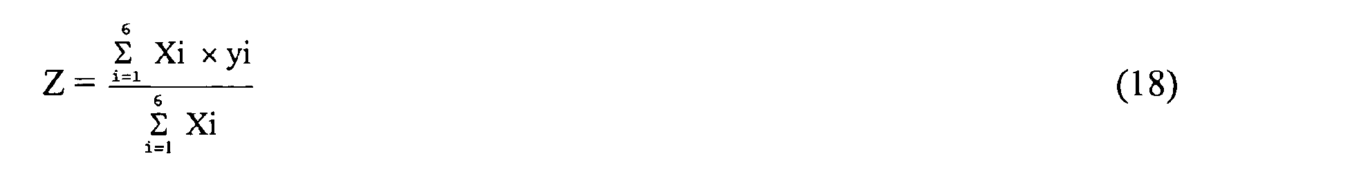
| Control method of water spray amount | |
| (1) | When furnace exit temperature is low (S1) → decrease water spray amount by a specific amount. |
| (2) | When NOx concentration is high (S2) and furnace exit temperature is also high (S3) → increase water spray amount by a specific amount. |
| (3) | When furnace exit temperature is high (S4) → increase water spray amount by a specific amount. |
| Fuzzy control method of water spray amount | |
| (1) | When furnace exit temperature is low → decrease water spray amount. |
| (2) | When furnace exit temperature is adequate → maintain present water spray amount. |
| (3) | When NOx concentration is adequate → maintain present water spray amount. |
| (4) | When furnace exit temperature is high → increase water spray amount. |
| (5) | When furnace exit temperature is high and NOx concentration is also high → increase water spray amount. |
| Rule | Antecedent (input) | Consequent (output) | ||
| No | Goodness of fit | Furnace exit temperature | NOx concentration | ΔWater spray amount |
| (1) | X1 | Low (a1 ) | Decrease (y1) | |
| (2) | X2 | Adequate (a2) | Maintain present level (y2) | |
| (3) | X3 | Adequate (b1) | Maintain present level (y3) | |
| (4) | X4 | High (a3) | Increase (y4) | |
| (5) | X5 | High (a3) | High (b2) | Increase (y5) |

| Control method of water spray amount | |
| (1) | When O2 concentration is high (S1) → decrease water spray amount by a specific amount. |
| (2) | When CO concentration is high (S2) → decrease water spray amount by a specific amount. |
| (3) | When NOx concentration is high (S3) and O2 concentration is also low (S4) → increase water spray amount by a specific amount. |
| (4) | When O2 concentration is low (S5) → increase water spray amount by a specific amount. |
| Fuzzy control method of water spray amount | |
| (1) | When O2 concentration is high → decrease water spray amount. |
| (2) | When CO concentration is high → decrease water spray amount. |
| (3) | When O2 concentration is adequate → maintain present water spray amount. |
| (4) | When NOx concentration is adequate → maintain present water spray amount. |
| (5) | When O2 concentration is low → increase water spray amount. |
| (6) | When O2 concentration is low and NOx concentration is also high → increase water spray amount. |
| Rule | Antecedent (input) | Consequent (output) | |||
| No | Goodness of fit | O2 concentration | CO concentration | NOx concentration | ΔWater spray amount |
| (1) | X1 | High (a3) | Decrease (y1) | ||
| (2) | X2 | High (b2) | Decrease (y2) | ||
| (3) | X3 | Adequate (a2) | Maintain present level (Y3) | ||
| (4) | X4 | Adequate (C1) | Maintain present level (y4) | ||
| (5) | X5 | Low (a1) | Increase (y5) | ||
| (6) | X6 | Low (a1) | High(C2) | Increase (y6) |
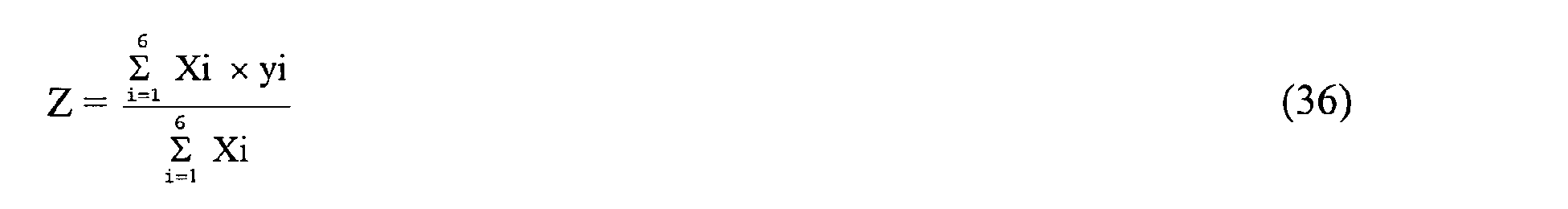
| Control method of water spray amount | |
| (1) | When O2 concentration is high (S1) → decrease water spray amount by a specific amount. |
| (2) | When NOx concentration is high (S2) and O2 concentration is also low (S3) → increase water spray amount by a specific amount. |
| (3) | When O2 concentration is low (S4) → increase water spray amount by a specific amount. |
| Fuzzy control method of water spray amount | |
| (1) | When O2 concentration is high → decrease water spray amount. |
| (2) | When O2 concentration is adequate → maintain present water spray amount. |
| (3) | When NOx concentration is adequate → maintain present water spray amount. |
| (4) | When O2 concentration is low → increase water spray amount. |
| (5) | When O2 concentration is low and NOx concentration is also high → increase water spray amount. |
| Rule | Antecedent (input) | Consequent (output) | ||
| No | Goodness of fit | O2 concentration | NOx concentration | ΔWater spray amount |
| (1) | X1 | High (a3) | Decrease (y1) | |
| (2) | X2 | Adequate (a2) | Maintain present level (y2) | |
| (3) | X3 | Adequate (b1) | Maintain present level (y3) | |
| (4) | X4 | Low (a1) | Increase (y4) | |
| (5) | X5 | Low (a1) | Adequate (b2) | Increase (y5) |

| Fuzzy control method of water spray amount | |
| (1) | When furnace exit temperature is low → decrease water spray amount. |
| (2) | When furnace exit temperature is adequate → maintain present water spray amount. |
| (3) | When NOx concentration is adequate → maintain present water spray amount. |
| (4) | When furnace exit temperature is high → increase water spray amount. |
| (5) | When furnace exit temperature is high and NOx concentration is also high → increase water spray amount. |
| Rule | Antecedent (input) | Consequent (output) | ||
| No | Goodness of fit | Furnace exit temperature | NOx concentration | ΔWater spray amount |
| (1) | X1 | Low (a1) | Decrease (y1) | |
| (2) | X2 | Adequate (a2) | Maintain present level (y2) | |
| (3) | X3 | Adequate (b1) | Maintain present level (y3) | |
| (4) | X4 | High (a3) | Increase (y4) | |
| (5) | X5 | High (a3) | High (b2) | Increase (y5) |
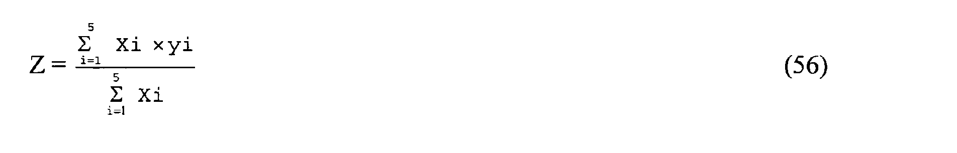
| Fuzzy control method of secondary combustion air quantity | |
| (1) | When furnace exit temperature is low and secondary combustion air quantity is large → decrease secondary combustion air quantity. |
| (2) | When furnace exit temperature is high and secondary combustion air quantity is large → increase secondary combustion air quantity. |
| (3) | When furnace exit temperature is low and secondary combustion air quantity is small → increase secondary combustion air quantity. |
| (4) | When furnace exit temperature is high and secondary combustion air quantity is small → decrease secondary combustion air quantity. |
| (5) | When furnace exit temperature is high, secondary combustion air quantity is medium, and O2 concentration is high → decrease secondary combustion air quantity. |
| (6) | When furnace exit temperature is high, secondary combustion air quantity is medium, and O2 concentration is adequate → increase secondary combustion air quantity. |
| (7) | When furnace exit temperature is low and secondary combustion air quantity is medium → maintain the present level of secondary combustion air quantity. |
| (8) | When NOx concentration is high → decrease secondary combustion air quantity. |
| (9) | When secondary combustion air quantity is small and CO concentration is high → increase secondary combustion air quantity. |
| (10) | When O2 concentration is low → largely increase secondary combustion air quantity. |
| (11) | When furnace exit temperature is high and CO concentration is high → increase secondary combustion air quantity. |
| (12) | When CO concentration is adequate and also NOx is adequate → maintain the present level of secondary combustion air quantity. |
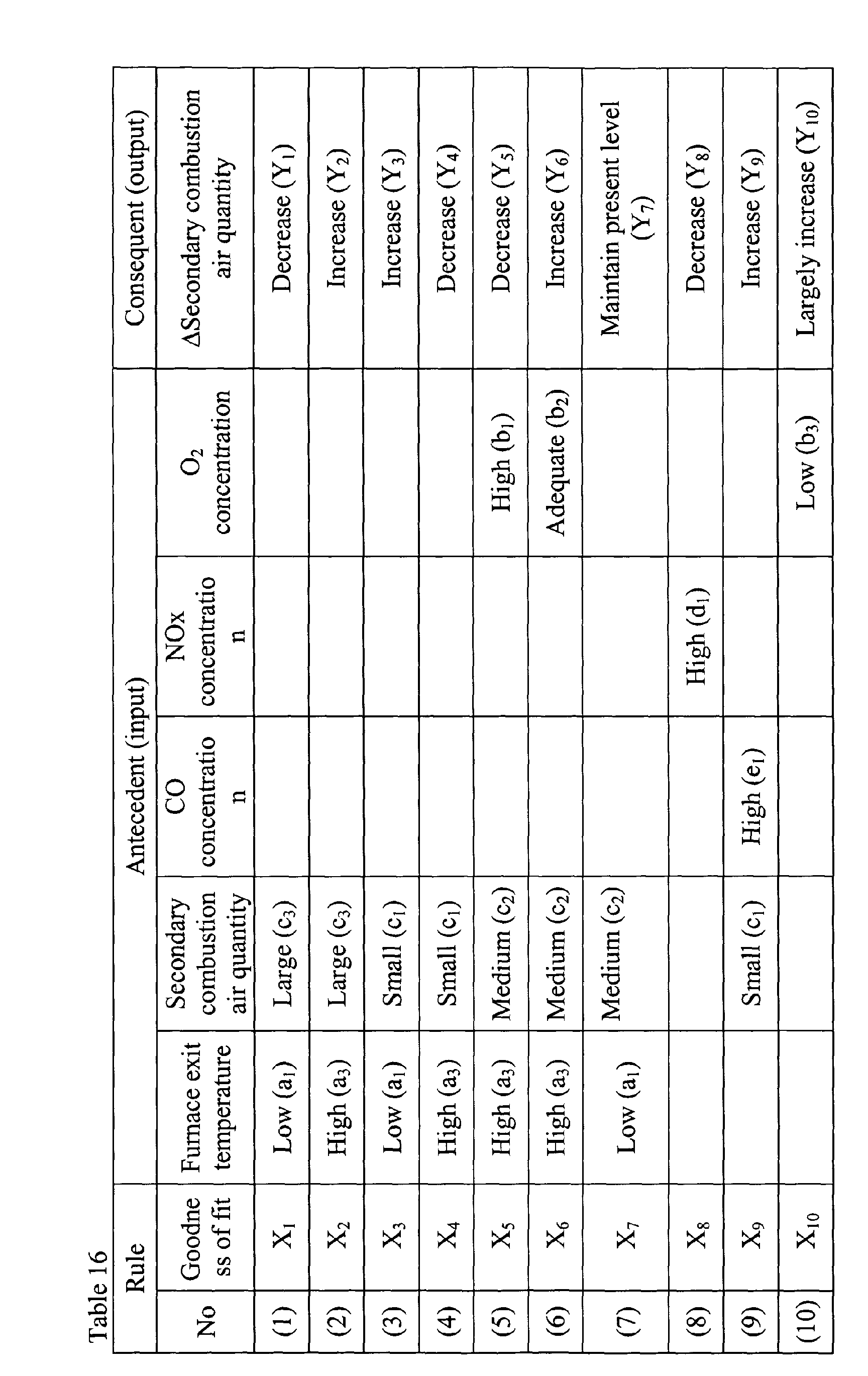
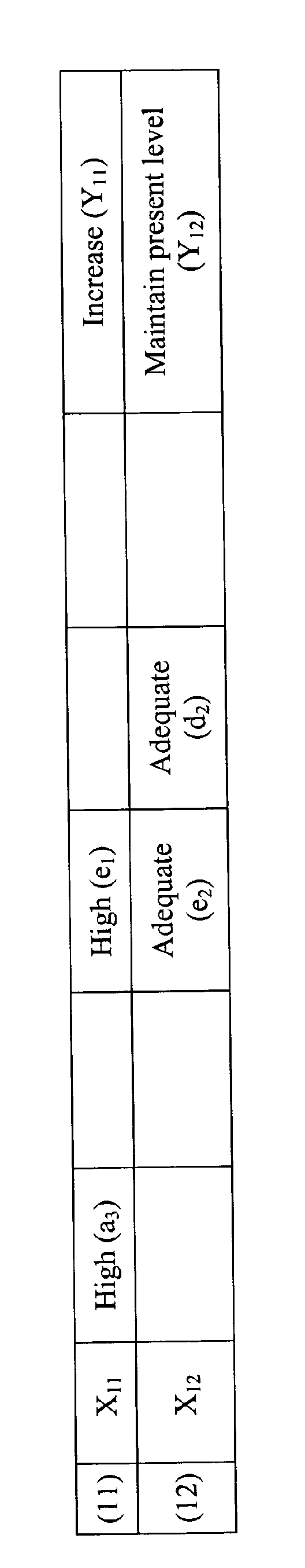
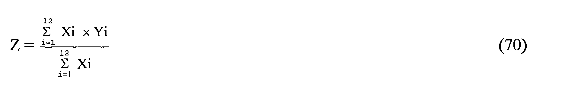
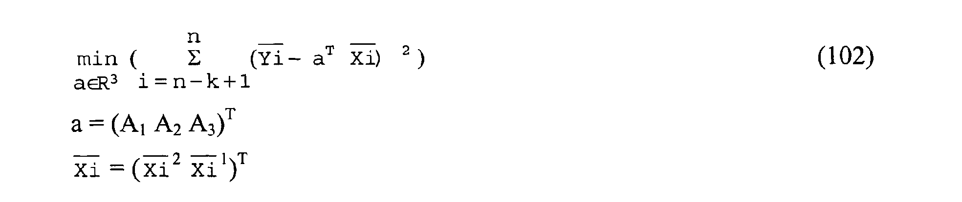
| Control method of secondary combustion air quantity | |
| (1) | When furnace exit temperature is low and secondary combustion air quantity is large → decrease secondary combustion air quantity. |
| (2) | When furnace exit temperature is low and secondary combustion air quantity is small → increase secondary combustion air quantity. |
| (3) | When furnace exit temperature is low and secondary combustion air quantity is adequate → maintain secondary combustion air quantity. |
| (4) | When furnace exit temperature is not low, secondary combustion air quantity is large, and boiler evaporation is large → increase secondary combustion air quantity. |
| (5) | When furnace exit temperature is not low, secondary combustion air quantity is large, and boiler evaporation is small → decrease secondary combustion air quantity. |
| (6) | When furnace exit temperature is not low, secondary combustion air quantity is large, and boiler evaporation is adequate → maintain secondary combustion air quantity. |
| (7) | When furnace exit temperature is not low, secondary combustion air quantity is small, and boiler evaporation is large → decrease secondary combustion air quantity. |
| (8) | When furnace exit temperature is not low, secondary combustion air quantity is small, and boiler evaporation is small → increase secondary combustion air quantity. |
| (9) | When furnace exit temperature is not low, secondary combustion air quantity is small, and boiler evaporation is adequate → maintain secondary combustion air quantity. |
| (10) | When furnace exit temperature is not low and secondary combustion air quantity is adequate → maintain secondary combustion air quantity. |
| (11) | When CO concentration is high and secondary combustion air quantity is large → decrease secondary combustion air quantity. |
| (12) | When CO concentration is high and secondary combustion air quantity is small → increase secondary combustion air quantity. |
| (13) | When O2 concentration is high → decrease secondary combustion air quantity. |
| (14) | When O2 concentration is low → increase secondary combustion air quantity. |
| (15) | When NOx concentration is high → decrease secondary combustion air quantity. |
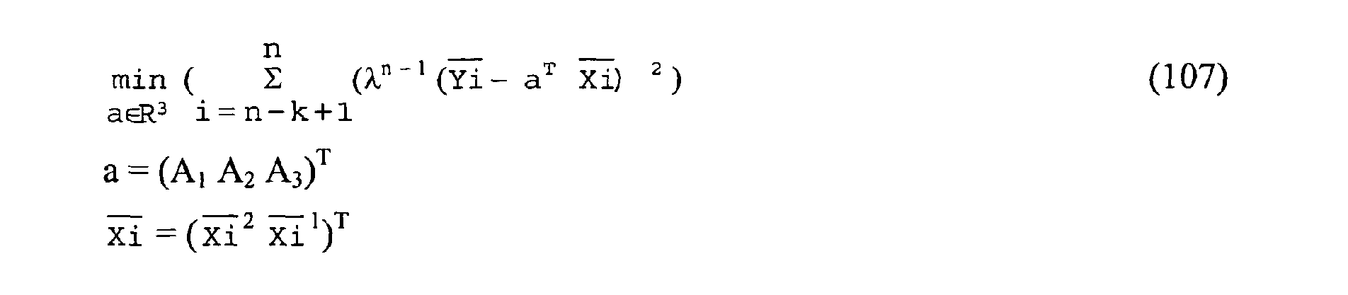
| Fuzzy control method of secondary combustion air quantity | |
| (1) | When furnace exit temperature is low → decrease secondary combustion air quantity. |
| (2) | When furnace exit temperature is slightly low and secondary combustion air quantity deviation is low → increase secondary combustion air quantity. |
| (3) | When furnace exit temperature is slightly low and secondary combustion air quantity deviation is high → decrease secondary combustion air quantity. |
| (4) | When furnace exit temperature is slightly low and secondary combustion air quantity deviation is adequate → maintain secondary combustion air quantity. |
| (5) | When furnace exit temperature is adequate, steam deviation is high, and secondary combustion air quantity deviation is low → decrease secondary combustion air quantity. |
| (6) | When furnace exit temperature is adequate, steam deviation is low, and secondary combustion air quantity deviation is low → increase secondary combustion air quantity. |
| (7) | When furnace exit temperature is adequate, steam deviation is high, and secondary combustion air quantity deviation is high → increase secondary combustion air quantity. |
| (8) | When furnace exit temperature is adequate, steam deviation is low, and secondary combustion air quantity deviation is high → decrease secondary combustion air quantity. |
| (9) | When furnace exit temperature is adequate, steam deviation is high, secondary combustion air quantity deviation is adequate, and O2 concentration is high → decrease secondary combustion air quantity. |
| (10) | When furnace exit temperature is adequate, steam deviation is high, secondary combustion air quantity deviation is adequate, and O2 concentration is adequate → increase secondary combustion air quantity. |
| (11) | When steam deviation is low and secondary combustion air quantity deviation is adequate → maintain secondary combustion air quantity. |
| (12) | When NOx concentration is high → decrease secondary combustion air quantity. |
| (13) | When furnace exit temperature is adequate and CO concentration is high → increase secondary combustion air quantity. |
| (14) | When furnace exit temperature is slightly low and CO concentration is high → increase secondary combustion air quantity. |
| (15) | When O2 concentration is low → increase secondary combustion air quantity. |
| (16) | When O2 concentration is very high → decrease secondary combustion air quantity. |
| (17) | When CO concentration is adequate and NOx concentration is adequate → maintain secondary combustion air quantity. |
| (18) | When O2 concentration is slightly low → increase secondary combustion air quantity. |


Claims (8)
- A combustion control method of a refuse incinerator (201) for burning refuse by utilising primary combustion air blown in from fire grates (203a,203b,203c) and secondary combustion air blown in above said fire grates, wherein a quantity of said secondary combustion air is controlled by control parameters such as a steam generation amount generated from a boiler (207) installed in said refuse incinerator, the secondary combustion air quantity, a temperature at an exit of the incinerator, and CO concentration, O2 concentration and NOx concentration in exhaust gas, so as to suppress generation of NOx in the exhaust gas, and said quantity of secondary combustion air is adjusted in accordance with the O2 concentration for minimising the concentration of precursors of dioxins estimated from the mutual relation of the concentration of said precursors of dioxins and O2 concentration in said exhaust gas, so as to suppress generation of dioxins in said exhaust gas.
- A combustion control method of a refuse incinerator according to claim 1, wherein said precursors of dioxins are chlorobenzenes and chlorophenols in said exhaust gas, and from the mutual relation between the sum of the concentration of these and O2 concentration in said exhaust gas, the O2 concentration for minimising the sum of the concentration of said chlorobenzenes and said chlorophenols is estimated.
- A combustion control method of a refuse incinerator according to claim 1, wherein said quantity of secondary combustion air is calculated by non-linear control to suppress generation of NOx in said exhaust gas, the concentration of said precursors of dioxins, that is, chlorobenzenes and chlorophenols is measured by a continuous or semi-continuous exhaust gas analyser (216) of a mutual relation between the sum of the concentration of these and O2 concentration is periodically calculated by a function approximating method, the O2 concentration for minimising the concentration of said chlorobenzenes and said chlorophenols is calculated, the control parameter of O2 concentration is sequentially corrected, and non-linear control is executed to adjust said quantity of secondary combustion air.
- A combustion control method of a refuse incinerator according to claim 3 wherein said non-linear control is fuzzy control.
- A combustion control apparatus of a refuse incinerator (201) comprising primary combustion control means (205) for feeding primary combustion air into the refuse incinerator to burn combustibles in the incinerator, and controlling an amount of steam generated in a boiler (207) to be stabilised, and secondary combustion air control means (210) for feeding secondary combustion air into the refuse incinerator for afterburning of unburnt components, further comprising: O2 concentration measuring means (213) for detecting O2 concentration in exhaust gas, exhaust gas analysing means (216) for measuring concentration of precursors of dioxins in exhaust gas, correlative curve estimating means (217a) for calculating a mutual relation between the concentration of precursors of dioxins detected by said exhaust gas analysing means and the O2 concentration detected by said O2 concentration measuring means, and operating means (217b) for calculating the O2 concentration for minimising the sum of the concentration of precursors of dioxins from a mutual relation determined by said correlative curve estimating means, wherein a quantity of the secondary combustion air is calculated by said secondary combustion control means by making use of control parameters on the basis of the O2 concentration calculated by said operating means, and said quantity is supplied into the incinerator to suppress generation of dioxins in exhaust gas.
- A combustion control apparatus of a refuse incinerator according to claim 5, wherein said precursors of dioxins are chlorobenzenes and chlorophenols.
- A combustion control apparatus of a refuse incinerator according to claim 5, wherein said secondary combustion air control means is to measure periodically the generated boiler steam amount, the quantity of secondary combustion air, a temperature at an exit (206) of the incinerator, and CO concentration, O2 concentration and NOx concentration in exhaust gas, and control the quantity of secondary combustion air on the basis of each measurement, said exhaust gas analysing means is a continuous or semi-continuous analyser for measuring chlorobenzenes and chlorophenols in exhaust gas, said correlative curve estimating means is to determine the mutual relation on the basis of the sum of the measured chlorobenzenes and chlorophenols and measure O2 concentration, said operating means is to calculating the O2 concentration for minimising the sum of the concentration of chlorobenzenes and chlorophenols in exhaust gas from said mutual relation, and by sequentially correcting the control parameters for calculating the secondary combustion air on the basis of the O2 concentration calculated by said operating means, the quantity of secondary combustion air is calculated by said secondary combustion air control means, and said quantity is supplied into the incinerator to thereby suppress generation of dioxins in exhaust gas.
- A combustion control apparatus of a refuse incinerator according to any one of claims 5 to 7, wherein said secondary combustion air control means makes use of fuzzy control.
Applications Claiming Priority (3)
| Application Number | Priority Date | Filing Date | Title |
|---|---|---|---|
| JP7356197 | 1997-03-26 | ||
| JP07356197A JP3319327B2 (en) | 1997-03-26 | 1997-03-26 | Combustion control method and device for refuse incinerator |
| EP97942222A EP0971169A4 (en) | 1997-03-26 | 1997-10-02 | COMBUSTION ADJUSTMENT METHOD AND DEVICE FOR WASTE INCINERATORS |
Related Parent Applications (1)
| Application Number | Title | Priority Date | Filing Date |
|---|---|---|---|
| EP97942222A Division EP0971169A4 (en) | 1997-03-26 | 1997-10-02 | COMBUSTION ADJUSTMENT METHOD AND DEVICE FOR WASTE INCINERATORS |
Publications (2)
| Publication Number | Publication Date |
|---|---|
| EP1382906A2 true EP1382906A2 (en) | 2004-01-21 |
| EP1382906A3 EP1382906A3 (en) | 2004-01-28 |
Family
ID=13521804
Family Applications (2)
| Application Number | Title | Priority Date | Filing Date |
|---|---|---|---|
| EP03078136A Withdrawn EP1382906A3 (en) | 1997-03-26 | 1997-10-02 | Combustion control method and apparatus for waste incinerators |
| EP97942222A Withdrawn EP0971169A4 (en) | 1997-03-26 | 1997-10-02 | COMBUSTION ADJUSTMENT METHOD AND DEVICE FOR WASTE INCINERATORS |
Family Applications After (1)
| Application Number | Title | Priority Date | Filing Date |
|---|---|---|---|
| EP97942222A Withdrawn EP0971169A4 (en) | 1997-03-26 | 1997-10-02 | COMBUSTION ADJUSTMENT METHOD AND DEVICE FOR WASTE INCINERATORS |
Country Status (4)
| Country | Link |
|---|---|
| EP (2) | EP1382906A3 (en) |
| JP (1) | JP3319327B2 (en) |
| KR (1) | KR100304244B1 (en) |
| WO (1) | WO1998043018A1 (en) |
Cited By (6)
| Publication number | Priority date | Publication date | Assignee | Title |
|---|---|---|---|---|
| WO2007090510A1 (en) * | 2006-02-07 | 2007-08-16 | Forschungszentrum Karlsruhe Gmbh | Method of reducing nitrogen oxide on the primary side in a two-stage combustion process |
| FR2941869A1 (en) * | 2009-02-10 | 2010-08-13 | Novergie | PROCESS FOR REDUCING NITROGEN OXIDES FROM COMBUSTION OF SOLID FUELS |
| EP2505919A1 (en) | 2011-03-29 | 2012-10-03 | Hitachi Zosen Inova AG | Method for optimising the burn-off of exhaust gases of an incinerator assembly by homogenization of the flue gases above the combustion bed by means of flue gas injection |
| EP2419495A4 (en) * | 2009-04-17 | 2013-11-13 | Proterrgo Inc | Method and apparatus for gasification of organic waste |
| KR20140131509A (en) * | 2012-02-28 | 2014-11-13 | 신닛떼쯔 수미킨 엔지니어링 가부시끼가이샤 | Waste gasification and melting furnace |
| US9139785B2 (en) | 2006-10-13 | 2015-09-22 | Proterrgo, Inc. | Method and apparatus for gasification of organic waste in batches |
Families Citing this family (23)
| Publication number | Priority date | Publication date | Assignee | Title |
|---|---|---|---|---|
| FR2785976B1 (en) * | 1998-11-17 | 2000-12-15 | Air Liquide | WASTE COMBUSTION PROCESS FOR REDUCING DIOXIN EMISSIONS |
| DE19923059A1 (en) * | 1999-05-20 | 2000-12-07 | Steag Ag | Process for controlling a combustion process |
| NL1013209C2 (en) * | 1999-10-04 | 2001-04-05 | Tno | Control system for an incineration plant, such as a waste incineration plant. |
| AU2002345182A1 (en) * | 2001-06-28 | 2003-03-03 | Invectoment Limited | Thermal treatment apparatus and method |
| US7373937B2 (en) | 2003-02-14 | 2008-05-20 | Fpi Fireplace Products International Ltd. | Draft control system and method for heating systems |
| DE102005009957B4 (en) * | 2005-03-04 | 2007-02-01 | Martin GmbH für Umwelt- und Energietechnik | Process for burning fuels, in particular waste |
| EP1785669A1 (en) * | 2005-11-09 | 2007-05-16 | Lentjes GmbH | Method for Controlling the Supply of Fuel to a Combustion Furnace |
| DE102006022657B4 (en) * | 2006-05-12 | 2011-03-03 | Alstom Technology Ltd. | Method and arrangement for regulating the air volume of a combustion system operated with fossil, solid fuels |
| KR100717395B1 (en) | 2006-06-03 | 2007-05-11 | 대림로얄보일러 주식회사 | Automatic combustion control system using exhaust gas analyzer of industrial boiler using ELENG |
| KR101005833B1 (en) * | 2008-12-30 | 2011-01-05 | (주)대우건설 | Optimization method of incinerator shape |
| JP6030913B2 (en) * | 2012-10-11 | 2016-11-24 | 川崎重工業株式会社 | Stoker-type incinerator |
| CN106705072A (en) * | 2016-11-23 | 2017-05-24 | 南京中船绿洲环保有限公司 | Ship incineration furnace hearth negative-pressure automatic control method and system |
| CN107101202A (en) * | 2017-04-28 | 2017-08-29 | 东南大学 | It is a kind of to reduce the processing method of Refuse Incineration Process Zhong bioxin growing amounts |
| KR20190002853U (en) | 2018-05-08 | 2019-11-18 | 덕왕 현 빌리안 | Moving apparatus having garbage incineration function |
| CN108980841A (en) * | 2018-06-14 | 2018-12-11 | 中国航天员科研训练中心 | Solid waste high-temperature oxidation device and method in a kind of closed environment system |
| CN109084324B (en) * | 2018-07-19 | 2019-09-27 | 北京德普新源科技发展有限公司 | The burning air quantity control system and control method of biomass boiler |
| WO2021051290A1 (en) * | 2019-09-18 | 2021-03-25 | 深圳市能源环保有限公司 | Automatic cooling control system for fire grate gap of garbage incinerator |
| CN110851497A (en) * | 2019-11-01 | 2020-02-28 | 唐山钢铁集团有限责任公司 | Method for detecting whether converter oxygen blowing is not ignited |
| CN111678135B (en) * | 2020-06-20 | 2025-06-13 | 郑州东兴环保能源有限公司 | One pit three furnaces urban domestic waste incinerator air and smoke system |
| CN112728554B (en) * | 2021-01-25 | 2024-09-06 | 华南理工大学 | A mixed feeding device for automatically adjusting the amount of stale garbage mixed with combustion |
| CN117167749B (en) * | 2022-09-02 | 2024-05-31 | 洛阳瑞昌环境工程有限公司 | Incineration system and incineration control method for nitrogen-containing waste |
| CN117167747A (en) * | 2023-09-28 | 2023-12-05 | 上海康和淼环境科技有限公司 | Incinerator control system and control method |
| CN120720599B (en) * | 2025-08-15 | 2025-11-14 | 中电行唐生物质能热电有限公司 | Multi-mode sensing-based automatic garbage combustion control method and system |
Family Cites Families (17)
| Publication number | Priority date | Publication date | Assignee | Title |
|---|---|---|---|---|
| JPS5642013A (en) * | 1979-09-14 | 1981-04-20 | Kubota Ltd | Incinerator |
| JPS59129316A (en) * | 1983-01-08 | 1984-07-25 | Kawasaki Heavy Ind Ltd | Dust feeding control device in refuse incinerater |
| JPS60162116A (en) * | 1984-01-31 | 1985-08-23 | Hitachi Zosen Corp | garbage incinerator |
| JPS60251310A (en) * | 1984-05-25 | 1985-12-12 | Kubota Ltd | How to operate an incinerator |
| JPH0247648B2 (en) * | 1984-12-17 | 1990-10-22 | Hitachi Shipbuilding Eng Co | NENSHOHAIGASUOMOCHIITABOIRACHUUBUNOFUSHOKUBOSHIHOHO |
| CH673149A5 (en) * | 1987-10-23 | 1990-02-15 | Kuepat Ag | |
| JPH07111247B2 (en) * | 1989-11-10 | 1995-11-29 | 石川島播磨重工業株式会社 | Waste treatment method |
| JPH079288B2 (en) * | 1990-11-30 | 1995-02-01 | 株式会社日立製作所 | Fuel supply control method for solid combustion device |
| US5052310A (en) * | 1991-01-22 | 1991-10-01 | Air Products And Chemicals, Inc. | Solid waste-to-steam incinerator capacity enhancement by combined oxygen enrichment and liquid quench |
| JP2696448B2 (en) * | 1991-10-07 | 1998-01-14 | 日立造船株式会社 | Garbage incinerator |
| JPH05248618A (en) | 1992-03-10 | 1993-09-24 | Kubota Corp | CO control method in incinerator |
| JPH05312796A (en) | 1992-05-14 | 1993-11-22 | Kubota Corp | Semi-continuous measuring and monitoring device for chlorobenzenes as an alternative index for dioxins in exhaust gas |
| JP2973154B2 (en) * | 1993-11-11 | 1999-11-08 | 住友重機械工業株式会社 | Combustion control method for incinerator |
| JP3461372B2 (en) * | 1993-12-13 | 2003-10-27 | バブコック日立株式会社 | Dust supply device control method |
| JPH07332642A (en) * | 1994-06-03 | 1995-12-22 | Kubota Corp | Garbage incinerator |
| JPH08128615A (en) * | 1994-11-01 | 1996-05-21 | Kubota Corp | Combustion control device for garbage incinerator |
| JP3425707B2 (en) * | 1995-06-02 | 2003-07-14 | Jfeエンジニアリング株式会社 | Combustion control device and method for refuse incinerator |
-
1997
- 1997-03-26 JP JP07356197A patent/JP3319327B2/en not_active Expired - Fee Related
- 1997-10-02 EP EP03078136A patent/EP1382906A3/en not_active Withdrawn
- 1997-10-02 EP EP97942222A patent/EP0971169A4/en not_active Withdrawn
- 1997-10-02 WO PCT/JP1997/003518 patent/WO1998043018A1/en not_active Ceased
- 1997-10-02 KR KR1019980710471A patent/KR100304244B1/en not_active Expired - Fee Related
Cited By (12)
| Publication number | Priority date | Publication date | Assignee | Title |
|---|---|---|---|---|
| WO2007090510A1 (en) * | 2006-02-07 | 2007-08-16 | Forschungszentrum Karlsruhe Gmbh | Method of reducing nitrogen oxide on the primary side in a two-stage combustion process |
| RU2394188C2 (en) * | 2006-02-07 | 2010-07-10 | Карлсруер Институт Фюр Технологи | Method for primary reduction of nitrogen oxide during two-step combustion process and device for primary reduction of nitrogen oxide during two-step combustion process |
| CN101379347B (en) * | 2006-02-07 | 2010-12-29 | 卡尔斯鲁厄研究中心股份有限公司 | Method for Reducing Nitrogen Oxide on Primary Side in Two-Stage Combustion Process |
| US8544394B2 (en) | 2006-02-07 | 2013-10-01 | Forschungszentrum Karlsruhe Gmbh | Method for reducing nitrogen oxide on the primary side in a two-stage combustion process |
| US9139785B2 (en) | 2006-10-13 | 2015-09-22 | Proterrgo, Inc. | Method and apparatus for gasification of organic waste in batches |
| FR2941869A1 (en) * | 2009-02-10 | 2010-08-13 | Novergie | PROCESS FOR REDUCING NITROGEN OXIDES FROM COMBUSTION OF SOLID FUELS |
| EP2419495A4 (en) * | 2009-04-17 | 2013-11-13 | Proterrgo Inc | Method and apparatus for gasification of organic waste |
| US9657941B2 (en) | 2009-04-17 | 2017-05-23 | Proterrgo Inc. | Method and apparatus for gasification of organic waste |
| EP2505919A1 (en) | 2011-03-29 | 2012-10-03 | Hitachi Zosen Inova AG | Method for optimising the burn-off of exhaust gases of an incinerator assembly by homogenization of the flue gases above the combustion bed by means of flue gas injection |
| WO2012130446A1 (en) | 2011-03-29 | 2012-10-04 | Hitachi Zosen Inova Ag | Method for optimising the burnout of exhaust gases of an incinerator |
| KR20140131509A (en) * | 2012-02-28 | 2014-11-13 | 신닛떼쯔 수미킨 엔지니어링 가부시끼가이샤 | Waste gasification and melting furnace |
| KR101890873B1 (en) | 2012-02-28 | 2018-08-22 | 신닛떼쯔 수미킨 엔지니어링 가부시끼가이샤 | Waste gasification and melting furnace |
Also Published As
| Publication number | Publication date |
|---|---|
| EP0971169A4 (en) | 2000-04-12 |
| EP0971169A1 (en) | 2000-01-12 |
| EP1382906A3 (en) | 2004-01-28 |
| WO1998043018A1 (en) | 1998-10-01 |
| JPH10267245A (en) | 1998-10-09 |
| JP3319327B2 (en) | 2002-08-26 |
| KR100304244B1 (en) | 2002-01-24 |
| KR20000022068A (en) | 2000-04-25 |
Similar Documents
| Publication | Publication Date | Title |
|---|---|---|
| EP1382906A2 (en) | Combustion control method and apparatus for waste incinerators | |
| US5606924A (en) | Process for regulating individual factors or all factors influencing combustion on a furnace grate | |
| CN101484753B (en) | Stoker-type incinerator and method for controlling combustion in the incinerator | |
| EP0507060B1 (en) | Method and apparatus for determining the amount of unburned in-ash component in waste gases of a powdered coal combustion system. | |
| EP0263195B1 (en) | Method and apparatus for controlling denitration of exhaust gas | |
| JP3822328B2 (en) | Method for estimating the lower heating value of combustion waste in refuse incinerators | |
| JP2019178848A (en) | Waste incinerator and waste incineration method | |
| JPH1068514A (en) | Combustion control method for refuse incinerator | |
| WO1998025078A1 (en) | Burning apparatus and method for restricting the occurrence of dioxins | |
| KR20000071727A (en) | Method for automatically setting the firing of a garbage incineration plant | |
| JP3783348B2 (en) | Dust supply control method and device for waste incinerator | |
| JP3556078B2 (en) | Dust supply speed control method for refuse incinerator and refuse incinerator | |
| KR100306291B1 (en) | Control method of flue gas mixture discharged from garbage incinerator | |
| JP3425707B2 (en) | Combustion control device and method for refuse incinerator | |
| JPH0468533B2 (en) | ||
| JPH0470528B2 (en) | ||
| JP3547296B2 (en) | Abnormality detection method of exhaust gas sensor and refuse incinerator | |
| JPH11108327A (en) | Garbage incinerator and its combustion control method | |
| JP2696448B2 (en) | Garbage incinerator | |
| JPH09273730A (en) | Method of suppressing unburned components in exhaust gas from refuse incinerator | |
| JPH0468534B2 (en) | ||
| JPH10332121A (en) | Combustion control method for refuse incinerator | |
| JPH09273732A (en) | Combustion control method for refuse incinerator | |
| JP3665476B2 (en) | Combustion control device for incinerator | |
| JPH09273733A (en) | Combustion control method for refuse incinerator |
Legal Events
| Date | Code | Title | Description |
|---|---|---|---|
| PUAI | Public reference made under article 153(3) epc to a published international application that has entered the european phase |
Free format text: ORIGINAL CODE: 0009012 |
|
| PUAL | Search report despatched |
Free format text: ORIGINAL CODE: 0009013 |
|
| AC | Divisional application: reference to earlier application |
Ref document number: 0971169 Country of ref document: EP Kind code of ref document: P |
|
| AK | Designated contracting states |
Kind code of ref document: A2 Designated state(s): BE DE DK FR GB |
|
| AK | Designated contracting states |
Kind code of ref document: A3 Designated state(s): BE DE DK FR GB |
|
| 17P | Request for examination filed |
Effective date: 20040226 |
|
| 17Q | First examination report despatched |
Effective date: 20040416 |
|
| AKX | Designation fees paid |
Designated state(s): BE DE DK FR GB |
|
| RAP1 | Party data changed (applicant data changed or rights of an application transferred) |
Owner name: JFE ENGINEERING CORPORATION |
|
| GRAP | Despatch of communication of intention to grant a patent |
Free format text: ORIGINAL CODE: EPIDOSNIGR1 |
|
| STAA | Information on the status of an ep patent application or granted ep patent |
Free format text: STATUS: THE APPLICATION IS DEEMED TO BE WITHDRAWN |
|
| 18D | Application deemed to be withdrawn |
Effective date: 20050725 |