EP1382900B2 - Projecteur de véhicule automobile avec lampe à deux filaments - Google Patents
Projecteur de véhicule automobile avec lampe à deux filaments Download PDFInfo
- Publication number
- EP1382900B2 EP1382900B2 EP03291723A EP03291723A EP1382900B2 EP 1382900 B2 EP1382900 B2 EP 1382900B2 EP 03291723 A EP03291723 A EP 03291723A EP 03291723 A EP03291723 A EP 03291723A EP 1382900 B2 EP1382900 B2 EP 1382900B2
- Authority
- EP
- European Patent Office
- Prior art keywords
- filament
- drl
- function
- reflector
- designed
- Prior art date
- Legal status (The legal status is an assumption and is not a legal conclusion. Google has not performed a legal analysis and makes no representation as to the accuracy of the status listed.)
- Expired - Lifetime
Links
Images


Classifications
-
- B—PERFORMING OPERATIONS; TRANSPORTING
- B60—VEHICLES IN GENERAL
- B60Q—ARRANGEMENT OF SIGNALLING OR LIGHTING DEVICES, THE MOUNTING OR SUPPORTING THEREOF OR CIRCUITS THEREFOR, FOR VEHICLES IN GENERAL
- B60Q1/00—Arrangement of optical signalling or lighting devices, the mounting or supporting thereof or circuits therefor
- B60Q1/26—Arrangement of optical signalling or lighting devices, the mounting or supporting thereof or circuits therefor the devices being primarily intended to indicate the vehicle, or parts thereof, or to give signals, to other traffic
- B60Q1/28—Arrangement of optical signalling or lighting devices, the mounting or supporting thereof or circuits therefor the devices being primarily intended to indicate the vehicle, or parts thereof, or to give signals, to other traffic for indicating front of vehicle
-
- B—PERFORMING OPERATIONS; TRANSPORTING
- B60—VEHICLES IN GENERAL
- B60Q—ARRANGEMENT OF SIGNALLING OR LIGHTING DEVICES, THE MOUNTING OR SUPPORTING THEREOF OR CIRCUITS THEREFOR, FOR VEHICLES IN GENERAL
- B60Q1/00—Arrangement of optical signalling or lighting devices, the mounting or supporting thereof or circuits therefor
- B60Q1/02—Arrangement of optical signalling or lighting devices, the mounting or supporting thereof or circuits therefor the devices being primarily intended to illuminate the way ahead or to illuminate other areas of way or environments
- B60Q1/04—Arrangement of optical signalling or lighting devices, the mounting or supporting thereof or circuits therefor the devices being primarily intended to illuminate the way ahead or to illuminate other areas of way or environments the devices being headlights
- B60Q1/14—Arrangement of optical signalling or lighting devices, the mounting or supporting thereof or circuits therefor the devices being primarily intended to illuminate the way ahead or to illuminate other areas of way or environments the devices being headlights having dimming means
- B60Q1/1415—Dimming circuits
- B60Q1/1423—Automatic dimming circuits, i.e. switching between high beam and low beam due to change of ambient light or light level in road traffic
- B60Q1/143—Automatic dimming circuits, i.e. switching between high beam and low beam due to change of ambient light or light level in road traffic combined with another condition, e.g. using vehicle recognition from camera images or activation of wipers
-
- F—MECHANICAL ENGINEERING; LIGHTING; HEATING; WEAPONS; BLASTING
- F21—LIGHTING
- F21S—NON-PORTABLE LIGHTING DEVICES; SYSTEMS THEREOF; VEHICLE LIGHTING DEVICES SPECIALLY ADAPTED FOR VEHICLE EXTERIORS
- F21S41/00—Illuminating devices specially adapted for vehicle exteriors, e.g. headlamps
- F21S41/10—Illuminating devices specially adapted for vehicle exteriors, e.g. headlamps characterised by the light source
- F21S41/14—Illuminating devices specially adapted for vehicle exteriors, e.g. headlamps characterised by the light source characterised by the type of light source
- F21S41/162—Incandescent light sources, e.g. filament or halogen lamps
- F21S41/164—Incandescent light sources, e.g. filament or halogen lamps having two or more filaments
-
- F—MECHANICAL ENGINEERING; LIGHTING; HEATING; WEAPONS; BLASTING
- F21—LIGHTING
- F21S—NON-PORTABLE LIGHTING DEVICES; SYSTEMS THEREOF; VEHICLE LIGHTING DEVICES SPECIALLY ADAPTED FOR VEHICLE EXTERIORS
- F21S41/00—Illuminating devices specially adapted for vehicle exteriors, e.g. headlamps
- F21S41/30—Illuminating devices specially adapted for vehicle exteriors, e.g. headlamps characterised by reflectors
- F21S41/32—Optical layout thereof
- F21S41/33—Multi-surface reflectors, e.g. reflectors with facets or reflectors with portions of different curvature
- F21S41/331—Multi-surface reflectors, e.g. reflectors with facets or reflectors with portions of different curvature the reflector consisting of complete annular areas
-
- B—PERFORMING OPERATIONS; TRANSPORTING
- B60—VEHICLES IN GENERAL
- B60Q—ARRANGEMENT OF SIGNALLING OR LIGHTING DEVICES, THE MOUNTING OR SUPPORTING THEREOF OR CIRCUITS THEREFOR, FOR VEHICLES IN GENERAL
- B60Q2400/00—Special features or arrangements of exterior signal lamps for vehicles
- B60Q2400/30—Daytime running lights [DRL], e.g. circuits or arrangements therefor
Definitions
- the invention relates to a motor vehicle headlamp of the type of those comprising: a lamp with two filaments, namely a first filament equipped with a cup which allows light to pass only within a given angular extent, and a second filament free of any cup; a reflector with a first reflecting zone provided essentially to cooperate with the first filament and producing a first type of light beam, and a second reflecting zone, located in the shadow of the cup, provided to cooperate with the second filament and to form, optionally with the first reflecting zone, a second type of light beam; and a mirror closure of the reflector.
- Such a projector is known and equipped, in particular, with a standard lamp of the "H4" type, or the like.
- the lamp "H4" is intended, in general, to produce a choice of a driving beam or a passing beam delimited by a cut, said European cut flattened V-shaped profile, having on the side of the crossing a horizontal edge, and the on the other side a rising edge at an angle ⁇ of 15 ° with respect to the horizontal.
- the photometry of the DRL function is relatively different from that of other lighting functions provided by motor vehicle headlamps.
- the DRL beam must be relatively thick along the optical axis, with a lower light intensity than for high beam or crossover.
- the illuminating surface required for the DRL function is 40 cm 2 and it is not always easy in modern vehicles to find a location for such illuminating surface.
- the invention overcomes these difficulties and prejudices, and made it possible to perform the DRL function with a motor vehicle headlamp which also provides an anti-fog function.
- a motor vehicle headlamp of the kind defined above is characterized in that one of the filaments of the lamp is provided to operate under a reduced electric power relative to that of the other filament and is assigned to the daytime running light (DRL), which the reflector is designed to provide with the reflective area assigned to this reduced power filament at least a portion of the DRL photometry, and that the projector has an illuminating surface at least equal to that required for the DRL function.
- DRL daytime running light
- the reflecting area of the reflector assigned to the function other than DRL is designed so as not to lead to values greater than the maximum allowed in DRL.
- the filament assigned to the function DRL would produce, under the nominal voltage applied to the other filament, a power greater than that desired; according to the invention, the filament assigned to the DRL function is under-volt, to produce the desired power.
- the dual filament lamp is designed such that the filament for the DRL function has a reduced power at the rated voltage equal to that applied to the other filament.
- the power for the DRL function is at most equal to one third of the power of the other filament.
- the filament DRL has a power of 16 W below the nominal voltage, while the other filament has a power of 65 W under the same nominal voltage.
- the vehicle headlamp can provide DRL function and fog function; the first filament with cup placed below is assigned to the fog function and the upper part of the reflector is designed for this function, while the second filament is assigned to the DRL function and the lower part of the reflector is designed for this function, possibly provided in conjunction with the upper part of the reflector.
- the upper part of the reflector can be intended to fill both the photometry of the fog lamp and a part of the DRL function, essentially that located above the horizontal plane, the lower part of the reflector being optimized to fill the photometry complementary to the DRL function.
- the lower part of the reflector comprises two end lateral zones provided for returning the light upwards and towards the center of the DRL beam.
- one of the side regions returns the light upward at an angle of about 5 ° to the optical axis, and the other extreme side zone returns the light upward at an angle of about 10 ° with respect to the optical axis.
- the fog beam can be cut off above a horizontal plane by the reflector whose focal point of the upper part is located behind the first filament with the cup associated with the fog lamp function.
- the reflector By providing the various light beams through the reflector, it can provide a completely smooth ice that does not intervene, for example by streaks, on the configuration of the beams.
- a schematic vertical section of a motor vehicle headlight P comprising a lamp L with two filaments, namely a first filament 1 equipped with a cup C which only allows light to pass through a given angular extent, and second filament 2 free of any cup.
- the lamp L in the example considered, is a standard lamp called H4.
- the filament 1 is located in front of the filament 2, the two filaments being generally cylindrical with respective axes parallel to the optical axis Ox of the projector.
- the filaments 1, 2 are further offset in height relative to each other.
- the filament 1 is disposed immediately above the optical axis Ox, tangentially to this axis, while the filament 2 is traversed by the axis Ox or is located below this axis.
- the cup C whose cross section is visible on Fig.2 , is formed by a revolution cylinder portion whose geometric axis is parallel to Ox, possibly coincident with this axis.
- the angular extent of the cross section of the cup C is 180 ° - ⁇ .
- the angle ⁇ in the example in question, is equal to 15 ° and corresponds to the angle defined by regulation for the inclined edge rising from the cut-off of the passing beam.
- the lamp L is conventionally used to provide the road and passing beam functions, it is oriented around the axis Ox so that an edge of the cup is in the horizontal plane of the axis Ox, while the other edge is on a radius inclined 15 ° below this plane.
- the lamp L is oriented as shown on Fig.2 so that the cup C is symmetrical with respect to the vertical plane V passing through the optical axis.
- the cup C lets the light pass symmetrically from each side of the plane V over an angular extent A equal to 90 ° + ⁇ / 2, that is, in the example considered, 97.5 °.
- the projector P comprises a reflector R which comprises a first reflective zone 3 constituted by the upper part of the reflector, that is to say the part essentially situated above the horizontal plane passing through the axis Ox.
- This upper part 3 which will be described in more detail with reference to the Figs.3 and 4 , is provided essentially to cooperate with the first filament 1 and produce a first type of light beam. In the example under consideration, it is a fog beam whose photometry in a vertical plane perpendicular to the optical axis and at a given distance from the headlamp is represented on Fig.9 .
- the focus F of the upper part 3 is located on the optical axis Ox behind the filament 1. The focus F can be located at the front end of the filament 2, as shown in FIG. Fig. 1 .
- the reflector R comprises a second zone 4 formed by a lower part located below the plane horizontal passing through the optical axis, and in the shadow of the cup C vis-à-vis the filament 1.
- This lower part 4 is provided to cooperate with the second filament 2.
- the front end of the filament 2 is located in rear of the rear end of the filament 1 at a distance d, for example of the order of 1.7 mm for a type of lamp H4.
- the lower part 4 of the reflector consists of several zones as illustrated on Figs.3, 5 and 6 , and will be described in more detail about these figures.
- the separation between the upper part 3 and the lower part 4 of the zones of the reflector R is formed by two lines Sa, Sb, inclined, from the central part towards the outside, by an angle greater than ⁇ / 2 downwards by ratio to the horizontal (10 ° in this case).
- the reflector R comprises in its central part, a circular opening E to receive a lamp holder.
- the headlamp P is closed, forwards, by a transparent glass G.
- one of the filaments of the lamp in the example considered the second filament 2, is provided to operate under a reduced electric power relative to that of the first filament 1 and is assigned to the function DRL (daytime running light). ).
- the operation of the second filament 2 under reduced power is obtained using an electrical circuit 5 reducing the voltage d supply of filament 2, which is thus under-volt.
- a filament 2 designed to operate at nominal voltage of 12 volts will be supplied by the circuit 5 at a voltage of 7 volts.
- a filament assigned to the DRL function has a power, at the rated voltage for example 12 volts, lower than that of the other filament and corresponding to the desired power for DRL photometry.
- the lower part 4 of the reflector is broken down into a central zone 4A illustrated on Fig.5 and in two extreme lateral zones 4B1, 4B2 illustrated on Fig.3 .
- the upper part 3 of the reflector as shown on Figs.3 and 4 consists of several facets symmetrical with respect to the vertical plane V passing through the optical axis. Each facet has a curved surface adapted to the part of the beam that it must produce in cooperation with one of the filaments.
- the upper part 3 comprises four facets respectively 3A1, 3B1, 3C1, 3D1 on the right of the plane V, and 3A2, 3B2, 3C2, 3D2 on the left.
- a transition line between each facet corresponds to a change of inclination as illustrated on Fig. 8 , but without there being a setback passing from one facet to another.
- the zone 4A of the lower part consists of a central part 4A1 of two immediately adjacent parts 4A2 and 4A3 and of two other outer parts 4A4 and 4A5.
- the lateral extreme parts 4B2, 4B1 come to frame the facets 4A4 and 4A5.
- the cooperation of the filament 2 with the upper part 3 is illustrated by the diagram of light ray on Fig.8 in a horizontal section passing through the optical axis of the lower zone of the upper part 3.
- the photometry produced by the zone 4A of the lower part cooperating with the filament 2 is illustrated by the isolux curves of Fig. 11 .
- the horizontal axis corresponds to the horizontal plane passing through the optical axis of the reflector.
- the graduations in% (percent) on this horizontal axis correspond to the tangent of the angle formed between the optical axis and a horizontal direction passing through the focus.
- the vertical axis corresponds to the trace of the vertical plane passing through the optical axis on the plane of photometry.
- the graduations in% (percent) of this vertical axis correspond to the tangent of the angle formed between the horizontal plane passing through the optical axis and a direction located in a vertical plane and passing through the focus of the reflector.
- the isolux curves of the beam produced by the zone 4A of the reflector in cooperation with the filament 2 are located below the horizontal plane passing through the optical axis and are substantially symmetrical with respect to the vertical axis.
- the luminous intensity levels of the various curves expressed in lux are given below.
- the closed central curve L1 corresponds to a level of 0.5 lux, the following curve L2 to a level of 0.250 lux, the penultimate curve L3 to a level of 0.1 lux and the last curve L4, consisting of two parts one low and one high, at a level of 0.01 lux.
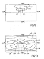
- the two side regions 4B1 and 4B2 of the lower part are provided to return a portion of the light beam upward as shown in FIG. Fig.7 preferably at an angle of 10 ° to the horizontal for one of the areas, for example the area 4B1, and at an angle of 5 ° to the horizontal for the other area 4B2.
- the photometry produced by the zones 4B1 and 4B2 in cooperation with the filament 2 is illustrated on Fig.12 .
- the isolux curves are located above the horizontal plane passing through the optical axis and extend on either side of the vertical plane passing through this optical axis.
- the central curve L5 corresponds to a level of 0.25 lux, the curves L6a and L6b to 0.1 lux and the external curve L7 to 0.010 lux.
- Part of the DRL beam is provided by the cooperation of the filament 2 with the upper part 3 of the reflector.
- the photometry of this part is illustrated on Fig.10 .
- the isolux curves are located on either side of the vertical plane passing through the optical axis and on both sides of the horizontal plane, being, however, tighter below this horizontal plane and further apart above. the vertical direction.
- the narrowest central curve L8 corresponds to a level of 1 lux and the successive concentric curves L9, L10, L11, L12 and L13 correspond respectively to 0.75, 0.5, 0.250, 0.1 and 0.01 lux.
- the photometry of the DRL beam resulting from the composition of the photometries of Fig.10, 11 and 12 is illustrated on Fig.13 .
- the curves L14, L15, (L16a, L16b), L17, L18, L19 correspond to respective levels of 1 lux, 0.75 lux, 0.5 lux, 0.250 lux, 0.1 lux and 0.01. lux.
- the upper part 3 of the reflector or mirror is optimized to satisfy the fog function ( Fig.9 ).
- This upper part 3 is however designed so that, used with the filament 2 ( Fig.10 ), it completes the DRL beam without leading to values higher than the maximum allowed.
- the lower part 4 of the mirror which is in the shadow of the cup C for the filament 1, is optimized for the filament 2 in order to satisfy the DRL function according to the diagrams of the Fig. 11 and 12 .
- the upper part 3 of the mirror in the example considered, is optimized to fill both the photometry of the fog lamp ( Fig.9 ) but also part of the DRL function ( Fig.10 ) makes it possible to reduce the dimensions of the reflector R.
- the under voltage of the filament 2 allows an increase in the life of this filament.
- the invention can be achieved with any two-filament lamp, one of which is equipped with a mask or cup shading a part of the mirror.
- the glass G of the headlamp can be completely smooth, the desired photometry being provided by the different parts of the reflector R.
- the invention also relates to the motor vehicle equipped with at least one of the projectors described above.
Landscapes
- Engineering & Computer Science (AREA)
- Mechanical Engineering (AREA)
- General Engineering & Computer Science (AREA)
- Non-Portable Lighting Devices Or Systems Thereof (AREA)
- Lighting Device Outwards From Vehicle And Optical Signal (AREA)
Description
- L'invention est relative à un projecteur de véhicule automobile du genre de ceux qui comprennent : une lampe à deux filaments, à savoir un premier filament équipé d'une coupelle qui ne laisse passer la lumière que suivant une étendue angulaire donnée, et un second filament libre de toute coupelle; un réflecteur avec une première zone réfléchissante prévue essentiellement pour coopérer avec le premier filament et produire un premier type de faisceau lumineux, et une seconde zone réfléchissante, située dans l'ombre de la coupelle, prévue pour coopérer avec le second filament et pour former, éventuellement avec la première zone réfléchissante, un deuxième type de faisceau lumineux; et une glace de fermeture du réflecteur.
- Un tel projecteur est connu et équipé, en particulier, d'une lampe normalisée de type "H4", ou analogue. La lampe "H4" est prévue pour, en général, produire au choix un faisceau de route ou un faisceau de croisement délimité par une coupure, dite coupure européenne à profil en V aplati, présentant du côté du croisement un bord horizontal, et de l'autre côté un bord montant suivant un angle α de 15° par rapport à l'horizontale.
- Il est également connu, notamment d'après
EP 0 581 679 qui divulgue le préambule de la revendication 1, de réaliser un projecteur bifonction route-antibrouillard dans lequel la lampe de type "H4" est décalée angulairement autour de son axe d'une valeur égale à α/2 par rapport à celle qu'elle occupe dans un projecteur classique route-code, ou est translatée vers le haut. - L'évolution des exigences en matière de signalisation des véhicules automobiles, notamment le règlement sur les feux diurnes de la Communauté Européenne intitulé "ECE regulation R87: Daytime Running Lamp" désigné ci-après par l'abréviation DRL, pose problème en matière de réalisation d'une telle fonction DRL.
- Une première solution admise pour assurer cette fonction DRL ou "feu diurne" consiste à allumer en permanence les feux de croisement (codes), comme les pays scandinaves le pratiquent actuellement. Toutefois, en procédant de la sorte, on augmente la consommation d'énergie de façon non négligeable, et on réduit la durée de vie des lampes. La photométrie du feu de croisement, tolérée pour cette fonction, n'est cependant pas la photométrie spécifique de la fonction DRL.
- La photométrie de la fonction DRL est relativement différente de celle des autres fonctions d'éclairage assurées par les projecteurs de véhicules automobiles. En particulier, le faisceau DRL doit être relativement épais suivant l'axe optique, avec une intensité lumineuse plus faible que pour les feux de route ou de croisement.
- Il est possible de prévoir un feu diurne DRL spécifique, mais dans ce cas il faut ajouter à l'avant du véhicule, notamment dans le bouclier, une cavité respectant le règlement R87. Actuellement, la surface éclairante exigée pour la fonction DRL est de 40 cm2 et il n'est pas toujours aisé dans les véhicules modernes de trouver un emplacement pour une telle surface éclairante.
- Ces diverses exigences pour la fonction DRL apparaissent donc difficiles à concilier avec une autre fonction classique d' un projecteur de véhicule automobile.
- L'invention a surmonté ces difficultés et préjugés, et a permis de réaliser la fonction DRL avec un projecteur de véhicule automobile qui assure également une fonction antibrouillard.
- Selon l'invention, un projecteur de véhicule automobile du genre défini précédemment, est caractérisé par le fait que l'un des filaments de la lampe est prévu pour fonctionner sous une puissance électrique réduite relativement à celle de l'autre filament et est affecté à la fonction feu diurne (DRL), que le réflecteur est conçu pour assurer avec la zone réfléchissante affectée à ce filament de puissance réduite au moins une partie de la photométrie DRL, et que le projecteur a une surface éclairante au moins égale à celle nécessaire pour la fonction DRL.
- La zone réfléchissante du réflecteur affectée à la fonction autre que DRL est conçue de manière à ne pas conduire à des valeurs supérieures au maximum autorisé en DRL.
- Dans le cas d'une lampe à deux filaments qui ont sensiblement la même puissance sous une même tension ( ce qui est le cas d'une lampe de type "H4"), le filament affecté à la fonction DRL produirait, sous la tension nominale appliquée à l'autre filament , une puissance supérieure à celle souhaitée ; selon l'invention, le filament affecté à la fonction DRL est sous-volté , pour produire la puissance souhaitée.
- Selon une autre possibilité, la lampe à deux filaments est conçue de telle sorte que le filament servant à la fonction DRL a une puissance réduite sous la tension nominale, égale à celle appliquée à l'autre filament. En particulier, la puissance pour la fonction DRL est au plus égale au tiers de la puissance de l'autre filament. A titre d'exemple non limitatif, le filament DRL a une puissance de 16 W sous la tension nominale, tandis que l'autre filament a une puissance de 65 W sous la même tension nominale.
- Le projecteur de véhicule peut assurer la fonction DRL et la fonction antibrouillard; le premier filament avec coupelle placée au-dessous est affecté à la fonction antibrouillard et la partie haute du réflecteur est conçue pour cette fonction, tandis que le deuxième filament est affecté à la fonction DRL et la partie basse du réflecteur est conçue pour cette fonction, assurée éventuellement en liaison avec la partie haute du réflecteur.
- En effet, la partie haute du réflecteur peut être prévue pour remplir à la fois la photométrie de l'antibrouillard et une partie de la fonction DRL, essentiellement celle située au-dessus du plan horizontal, la partie basse du réflecteur étant optimisée pour remplir la photométrie complémentaire de la fonction DRL.
- Avantageusement, la partie basse du réflecteur comprend deux zones latérales d'extrémité prévues pour renvoyer la lumière vers le haut et vers le centre du faisceau DRL. De préférence, l'une des zones latérales renvoie la lumière vers le haut sous un angle d'environ 5° par rapport à l'axe optique, et l'autre zone latérale extrême renvoie la lumière vers le haut sous un angle d'environ 10° par rapport à l'axe optique.
- La coupure du faisceau antibrouillard au-dessus d'un plan horizontal peut être assurée par le réflecteur dont le foyer de la partie haute est situé en arrière du premier filament avec coupelle associé à la fonction antibrouillard.
- En assurant les divers faisceaux lumineux par le réflecteur, on peut prévoir une glace entièrement lisse qui n'intervient pas, par exemple par des stries, sur la configuration des faisceaux.
- L'invention consiste, mises à part les dispositions exposées ci-dessus, en un certain nombre d'autres dispositions dont il sera plus explicitement question ci-après à propos d'un exemple de réalisation décrit en détail avec référence aux dessins annexés, mais qui n'est nullement limitatif. Sur ces dessins :
-
Fig.1 est une vue schématique en coupe verticale d'un projecteur assurant la fonction DRL et une fonction antibrouillard selon l'invention. -
Fig.2 est une coupe schématique à plus grande échelle suivant la ligne II-II deFig.1 de la coupelle du premier filament. -
Fig.3 est une vue arrière du réflecteur avec les différentes zones réfléchissantes. -
Fig.4 est une vue arrière de la seule partie haute du réflecteur. -
Fig.5 est une vue arrière de la seule partie basse du réflecteur, sans les deux zones extrêmes latérales. -
Fig.6 est une vue arrière des deux seules zones extrêmes latérales de la partie basse réfléchissante. -
Fig.7 est une coupe schématique verticale du réflecteur illustrant la fonction DRL. -
Fig.8 est une coupe schématique par un plan horizontal, passant par l'axe optique, illustrant la contribution de la partie haute réfléchissante à la fonction DRL. -
Fig.9 illustre la photométrie de la fonction antibrouillard. -
Figs.10 à 12 illustrent la photométrie de trois composantes pour la fonction DRL obtenues avec les parties différentes du réflecteur montrées respectivement sur lesFigs. 4 à 6 . -
Fig.13 enfin illustre la photométrie complète DRL produite par l'ensemble des composantes desFig.10 à 12 . - En se reportant à
Fig.1 on peut voir une coupe verticale schématique d'un projecteur P de véhicule automobile comprenant une lampe L à deux filaments, à savoir un premier filament 1 équipé d'une coupelle C qui ne laisse passer la lumière que suivant une étendue angulaire donnée, et un second filament 2 libre de toute coupelle. - La lampe L, dans l'exemple considéré, est une lampe normalisée dite H4. Le filament 1 est situé en avant du filament 2, les deux filaments étant généralement cylindriques d'axe respectif parallèle à l'axe optique Ox du projecteur. Les filaments 1, 2 sont en outre décalés en hauteur l'un par rapport à l'autre. Le filament 1 est disposé immédiatement au-dessus de l'axe optique Ox, tangentiellement à cet axe, tandis que le filament 2 est traversé par l'axe Ox ou est situé au-dessous de cet axe.
- La coupelle C, dont la section transversale est visible sur
Fig.2 , est formée par une portion de cylindre de révolution dont l'axe géométrique est parallèle à Ox, éventuellement confondu avec cet axe. L'étendue angulaire de la section transversale de la coupelle C est égale à 180°- α . - L'angle α, dans l'exemple considéré, est égal à 15° et correspond à l'angle défini réglementairement pour le bord incliné montant de la coupure du faisceau de croisement. Lorsque la lampe L est utilisée classiquement pour assurer les fonctions route et feu de croisement, elle est orientée autour de l'axe Ox de telle sorte qu'un bord de la coupelle se trouve dans le plan horizontal de l'axe Ox, tandis que l'autre bord se trouve sur un rayon incliné de 15° au-dessous de ce plan.
- Dans le cas du projecteur conforme à l'invention, la lampe L est orientée comme montré sur
Fig.2 de telle sorte que la coupelle C soit symétrique par rapport au plan vertical V passant par l'axe optique. La coupelle C laisse passer la lumière symétriquement de chaque côté du plan V sur une étendue angulaire A égale à 90° + α/2 soit, dans l'exemple considéré, 97,5°. - Le projecteur P comprend un réflecteur R qui comporte une première zone réfléchissante 3 constituée par la partie haute du réflecteur, c'est-à-dire la partie essentiellement située au-dessus du plan horizontal passant par l'axe Ox. Cette partie haute 3, qui sera décrite plus en détail avec référence aux
Figs.3 et 4 , est prévue essentiellement pour coopérer avec le premier filament 1 et produire un premier type de faisceau lumineux. Dans l'exemple considéré il s'agit d'un faisceau antibrouillard dont la photométrie dans un plan vertical perpendiculaire à l'axe optique et à une distance donnée du projecteur, est représentée surFig.9 . Le foyer F de la partie haute 3 est situé sur l'axe optique Ox en arrière du filament 1. Le foyer F peut être situé à l'extrémité avant du filament 2, comme illustré surFig. 1 . - Le réflecteur R comporte une seconde zone 4 formée par une partie basse située au-dessous du plan horizontal passant par l'axe optique, et dans l'ombre de la coupelle C vis-à-vis du filament 1. Cette partie basse 4 est prévue pour coopérer avec le second filament 2. L'extrémité avant du filament 2 est située en arrière de l'extrémité arrière du filament 1 à une distance d, par exemple de l'ordre de 1,7 mm pour une lampe de type H4. La partie basse 4 du réflecteur est constituée de plusieurs zones comme illustré sur
Figs.3, 5 et 6 , et sera décrite plus en détail à propos de ces figures. - La séparation entre la partie haute 3 et la partie basse 4 des zones du réflecteur R est formée par deux lignes Sa, Sb, inclinées, depuis la partie centrale vers l'extérieur, d'un angle supérieur à α/2 vers le bas par rapport à l'horizontale (10° dans le cas présent).
- Le réflecteur R comporte dans sa partie centrale, une ouverture circulaire E pour recevoir un porte-lampe.
- Le projecteur P est fermé, vers l'avant, par une glace transparente G.
- Selon l'invention, l'un des filaments de la lampe, dans l'exemple considéré le deuxième filament 2, est prévu pour fonctionner sous une puissance électrique réduite relativement à celle du premier filament 1 et est affecté à la fonction DRL (feu diurne).
- Dans le cas d'une lampe L de type H4 dont les deux filaments 1 et 2 ont sensiblement la même puissance électrique, le fonctionnement du deuxième filament 2 sous puissance réduite est obtenu à l'aide d'un circuit électrique 5 réduisant la tension d'alimentation du filament 2, qui est ainsi sous-volté. A titre d'exemple non limitatif, un filament 2 prévu pour fonctionner sous tension nominale de 12 volts, sera alimenté par le circuit 5 sous une tension de 7 volts.
- En variante, il est possible de prévoir et d'utiliser une lampe à deux filaments, dont un filament affecté à la fonction DRL a une puissance, sous la tension nominale par exemple de 12 volts, inférieure à celle de l'autre filament et correspondant à la puissance souhaitée pour la photométrie DRL.
- La partie basse 4 du réflecteur se décompose en une zone centrale 4A illustrée sur
Fig.5 et en deux zones latérales extrêmes 4B1, 4B2 illustrées surFig.3 . - La partie haute 3 du réflecteur, comme montré sur
Figs.3 et 4 se compose de plusieurs facettes symétriques par rapport au plan vertical V passant par l'axe optique. Chaque facette a une surface courbe adaptée à la partie du faisceau qu'elle doit produire en coopération avec l'un des filaments. De chaque côté du plan vertical V la partie haute 3 comprend quatre facettes respectivement 3A1, 3B1, 3C1, 3D1 sur la droite du plan V, et 3A2, 3B2, 3C2, 3D2 sur la gauche . Une ligne de transition entre chaque facette correspond à un changement d'inclinaison comme illustré surFig. 8 , mais sans qu'il y ait un décrochement en passant d'une facette à l'autre. - La zone 4A de la partie basse se compose d'une partie centrale 4A1 de deux parties immédiatement voisines 4A2 et 4A3 et de deux autres parties extérieures 4A4 et 4A5. Les parties extrêmes latérales 4B2, 4B1 viennent encadrer les facettes 4A4 et 4A5.
- La coopération du filament 2 avec la partie haute 3 est illustrée par le schéma de marche des rayons lumineux sur
Fig.8 selon une coupe horizontale passant par l'axe optique de la zone inférieure de la partie haute 3. - La photométrie produite par la zone 4A de la partie basse en coopérant avec le filament 2 est illustrée par les courbes isolux de
Fig. 11 . L'axe horizontal correspond au plan horizontal passant par l'axe optique du réflecteur. Les graduations en % (pour cent) sur cet axe horizontal correspondent à la tangente de l'angle formé entre l'axe optique et une direction horizontale passant par le foyer . L'axe vertical correspond à la trace du plan vertical passant par l'axe optique sur le plan de la photométrie. Les graduations en % (pour cent) de cet axe vertical correspondent à la tangente de l'angle formé entre le plan horizontal passant par l'axe optique et une direction située dans un plan vertical et passant par le foyer du réflecteur. - On voit, d'après
Fig.11 que les courbes isolux du faisceau produit par la zone 4A du réflecteur en coopération avec le filament 2, sont situées au-dessous du plan horizontal passant par l'axe optique et sont sensiblement symétriques par rapport à l'axe vertical. Les niveaux d'intensité lumineuse des différentes courbes exprimés en lux sont donnés ci-après. La courbe centrale fermée L1 correspond à un niveau de 0.5 lux, la courbe suivante L2 à un niveau de 0.250 lux, l'avant-dernière courbe L3 à un niveau de 0.1 lux et la dernière courbe L4, constituée de deux parties l'une basse et l'une haute, à un niveau de 0.01 lux. - Les deux zones latérales 4B1 et 4B2 de la partie basse sont prévues pour renvoyer une partie du faisceau lumineux vers le haut comme illustré sur
Fig.7 , de préférence sous un angle de 10° par rapport à l'horizontale pour l'une des zones, par exemple la zone 4B1, et sous un angle de 5° par rapport à l'horizontale pour l'autre zone 4B2. - La photométrie produite par les zones 4B1 et 4B2 en coopération avec le filament 2 est illustrée sur
Fig.12 . Les courbes isolux sont situées au-dessus du plan horizontal passant par l'axe optique et s'étendent de part et d'autre du plan vertical passant par cet axe optique. La courbe centrale L5 correspond à un niveau de 0.25 lux , les courbes L6a et L6b à 0.1 lux et la courbe extérieure L7 à 0.010 lux. - Une partie du faisceau DRL est assurée par la coopération du filament 2 avec la partie haute 3 du réflecteur. La photométrie de cette partie est illustrée sur
Fig.10 . Les courbes isolux sont situées de part et d'autre du plan vertical passant par l'axe optique et de part et d'autre du plan horizontal, en étant toutefois plus serrées au-dessous de ce plan horizontal et plus écartées au-dessus suivant la direction verticale. La courbe centrale L8 la plus étroite correspond à un niveau de 1 lux et les courbes concentriques successives L9, L10, L11, L12 et L13 correspondent respectivement à 0.75, 0.5, 0.250, 0.1 et 0.01 lux. - La photométrie du faisceau DRL résultant de la composition des photométries des
Fig.10, 11 et12 est illustrée surFig.13 . De la zone centrale, vers l'extérieur, les courbes L14, L15, (L16a, L16b), L17, L18, L19, correspondent à des niveaux respectifs de 1 lux, 0.75 lux, 0.5 lux, 0.250 lux , 0.1 lux et 0.01 lux. - Ainsi, selon l'invention, la partie haute 3 du réflecteur ou miroir est optimisée pour satisfaire la fonction antibrouillard (
Fig.9 ). Cette partie haute 3 est cependant conçue de manière à ce que, utilisée avec le filament 2 (Fig.10 ), elle complète le faisceau DRL sans conduire à des valeurs supérieures au maximum autorisé. - La partie basse 4 du miroir, qui se trouve dans l'ombre de la coupelle C pour le filament 1 est optimisée pour le filament 2 afin de satisfaire la fonction DRL selon les schémas des
Fig. 11 et12 . - La partie haute 3 du miroir, dans l'exemple considéré, étant optimisée pour remplir à la fois la photométrie de l'antibrouillard (
Fig.9 ) mais aussi une partie de la fonction DRL (Fig.10 ) permet de réduire les dimensions du réflecteur R. - La description a été effectuée à propos d'un projecteur bifonction antibrouillard-DRL.
- Dans le cas où la lampe L est une lampe du type H4, le sous-voltage du filament 2 permet une augmentation de la durée de vie de ce filament.
- Il est à noter que l'invention peut être réalisée avec toute lampe à deux filaments dont l'un est équipé d'un masque ou coupelle faisant de l'ombre sur une partie du miroir.
- La glace G du projecteur peut être entièrement lisse, la photométrie souhaitée étant assurée par les différentes parties du réflecteur R.
- L'invention a également pour objet le véhicule automobile équipé d'au moins un des projecteurs décrits plus haut.
Claims (9)
- Projecteur de véhicule automobile comprenant : une lampe (L) à deux filaments, à savoir un premier filament (1) équipé d'une coupelle (C) qui ne laisse passer la lumière que suivant une étendue angulaire donnée, et un second filament (2) libre de toute coupelle; un réflecteur (R) avec une première zone réfléchissante (3) prévue essentiellement pour coopérer avec le premier filament (1) et produire un premier type de faisceau lumineux, et une seconde zone réfléchissante (4), située dans l'ombre de la coupelle (C), prévue pour coopérer avec le second filament (2) et pour former, éventuellement avec la première zone réfléchissante, un deuxième type de faisceau lumineux; et une glace (G) de fermeture du réflecteur, le premier filament (1) avec coupelle étant affecté à la fonction antibrouillard et la partie haute (3) du réflecteur étant conçue pour cette fonction, caractérisé en ce que le second filament (2) de la lampe est prévu pour fonctionner sous une puissance électrique réduite relativement à celle de l'autre filament (1) et est affecté à la fonction feu diurne (DRL), en ce que le réflecteur (R) est conçu pour assurer avec la zone seconde, réfléchissante (4) affectée à ce filament (2) de puissance réduite au moins une partie de la photométrie DRL, et en ce que le projecteur (P) a une surface éclairante au moins égale à celle nécessaire pour la fonction DRL, la partie basse (4) du réflecteur étant conçue pour la fonction DRL et comprenant deux zones latérales d'extrémité (4B1, 4B2) prévues pour renvoyer la lumière vers le haut et vers le centre du faisceau DRL.
- Projecteur selon la revendication 1, caractérisé par le fait que la zone réfléchissante (3) du réflecteur affectée à la fonction autre que DRL est conçue de manière à ne pas conduire à des valeurs supérieures au maximum autorisé en DRL.
- Projecteur selon la revendication 1 ou 2, équipé d'une lampe à deux filaments qui ont sensiblement la même puissance sous une même tension caractérisé par le fait que le filament (2) affecté à la fonction DRL est sous-volté.
- Projecteur selon la revendication 3, caractérisé par le fait qu'il comporte un circuit (5) pour réduire la tension d'alimentation du filament (2) affecté à la fonction DRL.
- Projecteur selon la revendication 1 ou 2, caractérisé par le fait qu'il comporte une lampe à deux filaments conçue de telle sorte que le filament (2) servant à la fonction DRL a une puissance réduite sous la tension nominale, qui est celle appliquée à l'autre filament (1).
- Projecteur selon l'une des revendications précédentes, caractérisé par le fait que le filament (2) pour la fonction DRL fonctionne sous une puissance au plus égale au tiers de la puissance de l'autre filament (1).
- Projecteur selon l'une des revendications précédentes, caractérisé par le fait que la partie haute (3) du réflecteur est prévue pour remplir à la fois la photométrie de l'antibrouillard et une partie de la fonction DRL, essentiellement celle située au-dessus du plan horizontal, la partie basse (4) du réflecteur étant optimisée pour remplir la photométrie complémentaire de la fonction DRL.
- Projecteur selon l'une des revendications précédentes, caractérisé par le fait que la glace de fermeture (G) est lisse.
- véhicule automobile caractérisé en ce qu'il est équipé d'au moins un projecteur selon l'une au moins des revendications précédentes.
Applications Claiming Priority (2)
| Application Number | Priority Date | Filing Date | Title |
|---|---|---|---|
| FR0208936A FR2842282B1 (fr) | 2002-07-15 | 2002-07-15 | Projecteur de vehicule automobile avec lampe a deux filaments |
| FR0208936 | 2002-07-15 |
Publications (3)
| Publication Number | Publication Date |
|---|---|
| EP1382900A1 EP1382900A1 (fr) | 2004-01-21 |
| EP1382900B1 EP1382900B1 (fr) | 2005-10-19 |
| EP1382900B2 true EP1382900B2 (fr) | 2009-10-21 |
Family
ID=29763882
Family Applications (1)
| Application Number | Title | Priority Date | Filing Date |
|---|---|---|---|
| EP03291723A Expired - Lifetime EP1382900B2 (fr) | 2002-07-15 | 2003-07-10 | Projecteur de véhicule automobile avec lampe à deux filaments |
Country Status (5)
| Country | Link |
|---|---|
| EP (1) | EP1382900B2 (fr) |
| AT (1) | ATE307319T1 (fr) |
| DE (1) | DE60301921T3 (fr) |
| ES (1) | ES2249694T5 (fr) |
| FR (1) | FR2842282B1 (fr) |
Families Citing this family (9)
| Publication number | Priority date | Publication date | Assignee | Title |
|---|---|---|---|---|
| FR2872564B1 (fr) * | 2004-07-02 | 2007-03-16 | Valeo Vision Sa | Dispositif d'eclairage et/ou de signalisation pour vehicule automobile |
| EP1892461B1 (fr) * | 2006-08-25 | 2013-03-13 | Hella KGaA Hueck & Co. | Projecteur pour un véhicule |
| ATE439551T1 (de) * | 2006-09-19 | 2009-08-15 | Peugeot Citroen Automobiles Sa | Kraftfahrzeugscheinwerfer mit zwei funktionen |
| DE102006047837A1 (de) * | 2006-10-10 | 2008-04-17 | Volkswagen Ag | Scheinwerfer für ein Fahrzeug mit einer Tagfahrlichtanordnung |
| FR2911663B1 (fr) * | 2007-01-22 | 2009-04-17 | Valeo Vision Sa | Module optique multifonction de vehicule automobile |
| DE102007062136A1 (de) * | 2007-12-21 | 2009-06-25 | Hella Kgaa Hueck & Co. | Scheinwerfer für Fahrzeuge |
| JP5368699B2 (ja) * | 2007-12-27 | 2013-12-18 | 株式会社小糸製作所 | 車両用前照灯 |
| US9631785B2 (en) | 2008-09-18 | 2017-04-25 | Koninklijke Philips N.V. | Lighting unit and vehicle headlamp |
| FR2965325B1 (fr) * | 2010-09-29 | 2015-09-25 | Valeo Vision | Dispositif d'eclairage et de signalisation d'un vehicule automobile et procede de fonctionnement d'un tel dispositif |
Citations (3)
| Publication number | Priority date | Publication date | Assignee | Title |
|---|---|---|---|---|
| DE3533117A1 (de) † | 1985-09-17 | 1987-03-26 | Bosch Gmbh Robert | Scheinwerfer fuer das gemeinsame nebellicht und fernlicht von kraftfahrzeugen |
| EP0684420A1 (fr) † | 1994-05-26 | 1995-11-29 | Valeo Vision | Projecteur comportant une lampe à deux filaments pour engendrer un faisceau coupé et un faisceau non coupé |
| EP0791779A2 (fr) † | 1996-02-23 | 1997-08-27 | Hella KG Hueck & Co. | Projecteur de croisement et de route pour véhicule automobile et lampe |
Family Cites Families (3)
| Publication number | Priority date | Publication date | Assignee | Title |
|---|---|---|---|---|
| FR2694373B1 (fr) | 1992-07-30 | 1994-11-04 | Valeo Vision | Projecteur de véhicule automobile comportant une lampe à deux filaments pour engendrer sélectivement un faisceau antibrouillard et un faisceau de route. |
| FR2782149B1 (fr) * | 1998-08-10 | 2001-04-13 | Valeo Vision | Projecteur de vehicule automobile pourvu d'une lampe a deux filaments et d'un miroir perfectionnes |
| DE19946297A1 (de) * | 1999-09-28 | 2001-04-12 | Philips Corp Intellectual Pty | Glühlampe |
-
2002
- 2002-07-15 FR FR0208936A patent/FR2842282B1/fr not_active Expired - Fee Related
-
2003
- 2003-07-10 EP EP03291723A patent/EP1382900B2/fr not_active Expired - Lifetime
- 2003-07-10 AT AT03291723T patent/ATE307319T1/de not_active IP Right Cessation
- 2003-07-10 ES ES03291723T patent/ES2249694T5/es not_active Expired - Lifetime
- 2003-07-10 DE DE60301921T patent/DE60301921T3/de not_active Expired - Lifetime
Patent Citations (3)
| Publication number | Priority date | Publication date | Assignee | Title |
|---|---|---|---|---|
| DE3533117A1 (de) † | 1985-09-17 | 1987-03-26 | Bosch Gmbh Robert | Scheinwerfer fuer das gemeinsame nebellicht und fernlicht von kraftfahrzeugen |
| EP0684420A1 (fr) † | 1994-05-26 | 1995-11-29 | Valeo Vision | Projecteur comportant une lampe à deux filaments pour engendrer un faisceau coupé et un faisceau non coupé |
| EP0791779A2 (fr) † | 1996-02-23 | 1997-08-27 | Hella KG Hueck & Co. | Projecteur de croisement et de route pour véhicule automobile et lampe |
Non-Patent Citations (3)
| Title |
|---|
| UNITED NATIONS: "Agreement concerning the adoption of uniform conditions of approval and reciprocal recognition of approval for motor vehicle equipment and parts", ECE REGULATION NO. 87, 30 March 1993 (1993-03-30), GENEVA † |
| UNITED NATIONS: "Agreement concerning the adoption of uniform technical prescriptions for wheeled vehicles, equipment and parts which can be fitted and/or be used on wheeled vehicles and the conditions for reciprocal recognition of approvals granted on the basis of these", ECE REGULATIONS 87, 3 December 2003 (2003-12-03), GENEVA † |
| UNITED NATIONS: "Agreement concerning the adoption of uniform technical prescriptions for wheeles vehicles, equipment and parts which can be fitted and/or be used on wheeled vehicles and the conditions for reciprocal recognition of approvals granted on the basis of these", ECE REGULATIONS NO. 48, 20 March 2001 (2001-03-20), GENEVA † |
Also Published As
| Publication number | Publication date |
|---|---|
| FR2842282B1 (fr) | 2004-12-17 |
| ES2249694T5 (es) | 2010-02-01 |
| EP1382900B1 (fr) | 2005-10-19 |
| ES2249694T3 (es) | 2006-04-01 |
| DE60301921D1 (de) | 2006-03-02 |
| EP1382900A1 (fr) | 2004-01-21 |
| FR2842282A1 (fr) | 2004-01-16 |
| ATE307319T1 (de) | 2005-11-15 |
| DE60301921T3 (de) | 2010-03-11 |
| DE60301921T2 (de) | 2006-07-20 |
Similar Documents
| Publication | Publication Date | Title |
|---|---|---|
| EP0581679B1 (fr) | Projecteur de véhicule automobile comportant une lampe à deux filaments pour engendrer sélectivement un faisceau antibrouillard et un faisceau de route | |
| FR2883066A1 (fr) | Projecteur lumineux a plusieurs fonctions pour vehicule automobile | |
| EP0250284B1 (fr) | Projecteur de croisement sans coupelle à concentration décalée | |
| EP1600689B1 (fr) | Projecteur lumineux multifonction pour véhicule automobile | |
| FR2797680A1 (fr) | Phare pour vehicule | |
| EP1433999B1 (fr) | Projecteur a source lumineuse transversale pour vehicule automobile | |
| EP1382900B2 (fr) | Projecteur de véhicule automobile avec lampe à deux filaments | |
| EP1431654A1 (fr) | Projecteur de véhicule automobile assurant au moins deux fonctions | |
| FR2755748A1 (fr) | Projecteur de vehicule automobile, comportant une lampe a decharge a occulteurs et un reflecteur multi-zones | |
| EP0684420B1 (fr) | Projecteur comportant une lampe à deux filaments pour engendrer un faisceau coupé et un faisceau non coupé | |
| FR2834681A1 (fr) | Dispositif de phare de type a faisceau jumele pour moto | |
| US6409369B1 (en) | Dual function headlight for a motor vehicle with a single light source and fixed optics | |
| FR2609146A1 (fr) | Projecteur de vehicule automobile comportant un reflecteur parabolique a fond modifie | |
| EP1944542B1 (fr) | Projecteur lumineux de type bifonction pour véhicule automobile | |
| EP0258116B1 (fr) | Projecteur croisement-route à deux filaments transversaux pour véhicule automobile | |
| FR2810934A1 (fr) | Projecteur elliptique a modification de faisceau par mouvement d'elements optiques | |
| FR2760070A1 (fr) | Projecteur comportant une lampe a deux filaments pour engendrer un faisceau coupe et un faisceau non coupe | |
| EP1947380B1 (fr) | Module optique multifonction de véhicule automobile | |
| EP1870283B1 (fr) | Ensemble projecteur à trois fonctions pour véhicule automobile | |
| FR2808867A1 (fr) | Projecteur bi-fonction a source lumineuse unique et occulteur mobile pour vehicule automobile | |
| EP1241050B1 (fr) | Agencement d'un dispositif d'eclairage dans un vehicule automobile | |
| EP0926431A1 (fr) | Projecteur de véhicule automobile à miroir unique et source déplaçable pour engendrer deux faisceaux d'éclairage différents | |
| FR2675443A1 (fr) | Phare de vehicules. | |
| FR2769687A1 (fr) | Ensemble de projecteurs gauche et droit de vehicule automobile, a proprietes photometriques ameliorees | |
| EP1538393B1 (fr) | Projecteur verticalisé pour véhicule automobile |
Legal Events
| Date | Code | Title | Description |
|---|---|---|---|
| PUAI | Public reference made under article 153(3) epc to a published international application that has entered the european phase |
Free format text: ORIGINAL CODE: 0009012 |
|
| AK | Designated contracting states |
Kind code of ref document: A1 Designated state(s): AT BE BG CH CY CZ DE DK EE ES FI FR GB GR HU IE IT LI LU MC NL PT RO SE SI SK TR |
|
| AX | Request for extension of the european patent |
Extension state: AL LT LV MK |
|
| 17P | Request for examination filed |
Effective date: 20040611 |
|
| 17Q | First examination report despatched |
Effective date: 20040730 |
|
| AKX | Designation fees paid |
Designated state(s): AT BE BG CH CY CZ DE DK EE ES FI FR GB GR HU IE IT LI LU MC NL PT RO SE SI SK TR |
|
| GRAP | Despatch of communication of intention to grant a patent |
Free format text: ORIGINAL CODE: EPIDOSNIGR1 |
|
| GRAS | Grant fee paid |
Free format text: ORIGINAL CODE: EPIDOSNIGR3 |
|
| GRAA | (expected) grant |
Free format text: ORIGINAL CODE: 0009210 |
|
| AK | Designated contracting states |
Kind code of ref document: B1 Designated state(s): AT BE BG CH CY CZ DE DK EE ES FI FR GB GR HU IE IT LI LU MC NL PT RO SE SI SK TR |
|
| PG25 | Lapsed in a contracting state [announced via postgrant information from national office to epo] |
Ref country code: SI Free format text: LAPSE BECAUSE OF FAILURE TO SUBMIT A TRANSLATION OF THE DESCRIPTION OR TO PAY THE FEE WITHIN THE PRESCRIBED TIME-LIMIT Effective date: 20051019 Ref country code: GB Free format text: LAPSE BECAUSE OF FAILURE TO SUBMIT A TRANSLATION OF THE DESCRIPTION OR TO PAY THE FEE WITHIN THE PRESCRIBED TIME-LIMIT Effective date: 20051019 Ref country code: FI Free format text: LAPSE BECAUSE OF FAILURE TO SUBMIT A TRANSLATION OF THE DESCRIPTION OR TO PAY THE FEE WITHIN THE PRESCRIBED TIME-LIMIT Effective date: 20051019 Ref country code: RO Free format text: LAPSE BECAUSE OF FAILURE TO SUBMIT A TRANSLATION OF THE DESCRIPTION OR TO PAY THE FEE WITHIN THE PRESCRIBED TIME-LIMIT Effective date: 20051019 Ref country code: SK Free format text: LAPSE BECAUSE OF FAILURE TO SUBMIT A TRANSLATION OF THE DESCRIPTION OR TO PAY THE FEE WITHIN THE PRESCRIBED TIME-LIMIT Effective date: 20051019 Ref country code: AT Free format text: LAPSE BECAUSE OF FAILURE TO SUBMIT A TRANSLATION OF THE DESCRIPTION OR TO PAY THE FEE WITHIN THE PRESCRIBED TIME-LIMIT Effective date: 20051019 Ref country code: CZ Free format text: LAPSE BECAUSE OF FAILURE TO SUBMIT A TRANSLATION OF THE DESCRIPTION OR TO PAY THE FEE WITHIN THE PRESCRIBED TIME-LIMIT Effective date: 20051019 Ref country code: IE Free format text: LAPSE BECAUSE OF FAILURE TO SUBMIT A TRANSLATION OF THE DESCRIPTION OR TO PAY THE FEE WITHIN THE PRESCRIBED TIME-LIMIT Effective date: 20051019 |
|
| REG | Reference to a national code |
Ref country code: GB Ref legal event code: FG4D Free format text: NOT ENGLISH |
|
| REG | Reference to a national code |
Ref country code: CH Ref legal event code: EP |
|
| REG | Reference to a national code |
Ref country code: IE Ref legal event code: FG4D Free format text: LANGUAGE OF EP DOCUMENT: FRENCH |
|
| PG25 | Lapsed in a contracting state [announced via postgrant information from national office to epo] |
Ref country code: SE Free format text: LAPSE BECAUSE OF FAILURE TO SUBMIT A TRANSLATION OF THE DESCRIPTION OR TO PAY THE FEE WITHIN THE PRESCRIBED TIME-LIMIT Effective date: 20060119 Ref country code: BG Free format text: LAPSE BECAUSE OF FAILURE TO SUBMIT A TRANSLATION OF THE DESCRIPTION OR TO PAY THE FEE WITHIN THE PRESCRIBED TIME-LIMIT Effective date: 20060119 Ref country code: GR Free format text: LAPSE BECAUSE OF FAILURE TO SUBMIT A TRANSLATION OF THE DESCRIPTION OR TO PAY THE FEE WITHIN THE PRESCRIBED TIME-LIMIT Effective date: 20060119 Ref country code: DK Free format text: LAPSE BECAUSE OF FAILURE TO SUBMIT A TRANSLATION OF THE DESCRIPTION OR TO PAY THE FEE WITHIN THE PRESCRIBED TIME-LIMIT Effective date: 20060119 |
|
| REF | Corresponds to: |
Ref document number: 60301921 Country of ref document: DE Date of ref document: 20060302 Kind code of ref document: P |
|
| PG25 | Lapsed in a contracting state [announced via postgrant information from national office to epo] |
Ref country code: PT Free format text: LAPSE BECAUSE OF FAILURE TO SUBMIT A TRANSLATION OF THE DESCRIPTION OR TO PAY THE FEE WITHIN THE PRESCRIBED TIME-LIMIT Effective date: 20060320 |
|
| REG | Reference to a national code |
Ref country code: ES Ref legal event code: FG2A Ref document number: 2249694 Country of ref document: ES Kind code of ref document: T3 |
|
| PG25 | Lapsed in a contracting state [announced via postgrant information from national office to epo] |
Ref country code: HU Free format text: LAPSE BECAUSE OF FAILURE TO SUBMIT A TRANSLATION OF THE DESCRIPTION OR TO PAY THE FEE WITHIN THE PRESCRIBED TIME-LIMIT Effective date: 20060420 |
|
| GBV | Gb: ep patent (uk) treated as always having been void in accordance with gb section 77(7)/1977 [no translation filed] |
Effective date: 20051019 |
|
| REG | Reference to a national code |
Ref country code: IE Ref legal event code: FD4D |
|
| PG25 | Lapsed in a contracting state [announced via postgrant information from national office to epo] |
Ref country code: MC Free format text: LAPSE BECAUSE OF NON-PAYMENT OF DUE FEES Effective date: 20060731 Ref country code: BE Free format text: LAPSE BECAUSE OF NON-PAYMENT OF DUE FEES Effective date: 20060731 |
|
| PLBI | Opposition filed |
Free format text: ORIGINAL CODE: 0009260 |
|
| PLAX | Notice of opposition and request to file observation + time limit sent |
Free format text: ORIGINAL CODE: EPIDOSNOBS2 |
|
| 26 | Opposition filed |
Opponent name: AUTOMOTIVE LIGHTING REUTLINGEN GMBH Effective date: 20060719 |
|
| NLR1 | Nl: opposition has been filed with the epo |
Opponent name: AUTOMOTIVE LIGHTING REUTLINGEN GMBH |
|
| PLAF | Information modified related to communication of a notice of opposition and request to file observations + time limit |
Free format text: ORIGINAL CODE: EPIDOSCOBS2 |
|
| PLBB | Reply of patent proprietor to notice(s) of opposition received |
Free format text: ORIGINAL CODE: EPIDOSNOBS3 |
|
| REG | Reference to a national code |
Ref country code: FR Ref legal event code: ST Effective date: 20070330 |
|
| PLAB | Opposition data, opponent's data or that of the opponent's representative modified |
Free format text: ORIGINAL CODE: 0009299OPPO |
|
| R26 | Opposition filed (corrected) |
Opponent name: AUTOMOTIVE LIGHTING REUTLINGEN GMBH Effective date: 20060719 |
|
| NLR1 | Nl: opposition has been filed with the epo |
Opponent name: AUTOMOTIVE LIGHTING REUTLINGEN GMBH |
|
| BERE | Be: lapsed |
Owner name: VALEO VISION Effective date: 20060731 |
|
| REG | Reference to a national code |
Ref country code: CH Ref legal event code: PL |
|
| PG25 | Lapsed in a contracting state [announced via postgrant information from national office to epo] |
Ref country code: LI Free format text: LAPSE BECAUSE OF NON-PAYMENT OF DUE FEES Effective date: 20070731 Ref country code: CH Free format text: LAPSE BECAUSE OF NON-PAYMENT OF DUE FEES Effective date: 20070731 Ref country code: FR Free format text: LAPSE BECAUSE OF NON-PAYMENT OF DUE FEES Effective date: 20060731 |
|
| PG25 | Lapsed in a contracting state [announced via postgrant information from national office to epo] |
Ref country code: EE Free format text: LAPSE BECAUSE OF FAILURE TO SUBMIT A TRANSLATION OF THE DESCRIPTION OR TO PAY THE FEE WITHIN THE PRESCRIBED TIME-LIMIT Effective date: 20051019 |
|
| PLAB | Opposition data, opponent's data or that of the opponent's representative modified |
Free format text: ORIGINAL CODE: 0009299OPPO |
|
| PG25 | Lapsed in a contracting state [announced via postgrant information from national office to epo] |
Ref country code: LU Free format text: LAPSE BECAUSE OF NON-PAYMENT OF DUE FEES Effective date: 20060710 Ref country code: TR Free format text: LAPSE BECAUSE OF FAILURE TO SUBMIT A TRANSLATION OF THE DESCRIPTION OR TO PAY THE FEE WITHIN THE PRESCRIBED TIME-LIMIT Effective date: 20051019 |
|
| PG25 | Lapsed in a contracting state [announced via postgrant information from national office to epo] |
Ref country code: CY Free format text: LAPSE BECAUSE OF FAILURE TO SUBMIT A TRANSLATION OF THE DESCRIPTION OR TO PAY THE FEE WITHIN THE PRESCRIBED TIME-LIMIT Effective date: 20051019 |
|
| PUAH | Patent maintained in amended form |
Free format text: ORIGINAL CODE: 0009272 |
|
| STAA | Information on the status of an ep patent application or granted ep patent |
Free format text: STATUS: PATENT MAINTAINED AS AMENDED |
|
| 27A | Patent maintained in amended form |
Effective date: 20091021 |
|
| AK | Designated contracting states |
Kind code of ref document: B2 Designated state(s): AT BE BG CH CY CZ DE DK EE ES FI FR GB GR HU IE IT LI LU MC NL PT RO SE SI SK TR |
|
| NLR2 | Nl: decision of opposition |
Effective date: 20091021 |
|
| NLR3 | Nl: receipt of modified translations in the netherlands language after an opposition procedure | ||
| REG | Reference to a national code |
Ref country code: ES Ref legal event code: DC2A Date of ref document: 20091116 Kind code of ref document: T5 |
|
| REG | Reference to a national code |
Ref country code: DE Ref legal event code: R079 Ref document number: 60301921 Country of ref document: DE Free format text: PREVIOUS MAIN CLASS: F21S0008100000 Ipc: F21S0043000000 |
|
| PGFP | Annual fee paid to national office [announced via postgrant information from national office to epo] |
Ref country code: NL Payment date: 20190617 Year of fee payment: 17 |
|
| PGFP | Annual fee paid to national office [announced via postgrant information from national office to epo] |
Ref country code: IT Payment date: 20190718 Year of fee payment: 17 Ref country code: DE Payment date: 20190711 Year of fee payment: 17 Ref country code: ES Payment date: 20190809 Year of fee payment: 17 |
|
| REG | Reference to a national code |
Ref country code: DE Ref legal event code: R119 Ref document number: 60301921 Country of ref document: DE |
|
| REG | Reference to a national code |
Ref country code: NL Ref legal event code: MM Effective date: 20200801 |
|
| PG25 | Lapsed in a contracting state [announced via postgrant information from national office to epo] |
Ref country code: NL Free format text: LAPSE BECAUSE OF NON-PAYMENT OF DUE FEES Effective date: 20200801 |
|
| PG25 | Lapsed in a contracting state [announced via postgrant information from national office to epo] |
Ref country code: DE Free format text: LAPSE BECAUSE OF NON-PAYMENT OF DUE FEES Effective date: 20210202 |
|
| REG | Reference to a national code |
Ref country code: ES Ref legal event code: FD2A Effective date: 20211201 |
|
| PG25 | Lapsed in a contracting state [announced via postgrant information from national office to epo] |
Ref country code: ES Free format text: LAPSE BECAUSE OF NON-PAYMENT OF DUE FEES Effective date: 20200711 |
|
| PG25 | Lapsed in a contracting state [announced via postgrant information from national office to epo] |
Ref country code: IT Free format text: LAPSE BECAUSE OF NON-PAYMENT OF DUE FEES Effective date: 20200710 |