EP1382405A2 - Nietsetzwerkzeug zum Setzen von Blindnieten - Google Patents
Nietsetzwerkzeug zum Setzen von Blindnieten Download PDFInfo
- Publication number
- EP1382405A2 EP1382405A2 EP03015921A EP03015921A EP1382405A2 EP 1382405 A2 EP1382405 A2 EP 1382405A2 EP 03015921 A EP03015921 A EP 03015921A EP 03015921 A EP03015921 A EP 03015921A EP 1382405 A2 EP1382405 A2 EP 1382405A2
- Authority
- EP
- European Patent Office
- Prior art keywords
- fastener
- load
- setting
- setting tool
- tool
- Prior art date
- Legal status (The legal status is an assumption and is not a legal conclusion. Google has not performed a legal analysis and makes no representation as to the accuracy of the status listed.)
- Granted
Links
Images
Classifications
-
- B—PERFORMING OPERATIONS; TRANSPORTING
- B21—MECHANICAL METAL-WORKING WITHOUT ESSENTIALLY REMOVING MATERIAL; PUNCHING METAL
- B21J—FORGING; HAMMERING; PRESSING METAL; RIVETING; FORGE FURNACES
- B21J15/00—Riveting
- B21J15/10—Riveting machines
- B21J15/28—Control devices specially adapted to riveting machines not restricted to one of the preceding subgroups
- B21J15/285—Control devices specially adapted to riveting machines not restricted to one of the preceding subgroups for controlling the rivet upset cycle
-
- B—PERFORMING OPERATIONS; TRANSPORTING
- B21—MECHANICAL METAL-WORKING WITHOUT ESSENTIALLY REMOVING MATERIAL; PUNCHING METAL
- B21J—FORGING; HAMMERING; PRESSING METAL; RIVETING; FORGE FURNACES
- B21J15/00—Riveting
- B21J15/02—Riveting procedures
- B21J15/04—Riveting hollow rivets mechanically
- B21J15/043—Riveting hollow rivets mechanically by pulling a mandrel
-
- B—PERFORMING OPERATIONS; TRANSPORTING
- B21—MECHANICAL METAL-WORKING WITHOUT ESSENTIALLY REMOVING MATERIAL; PUNCHING METAL
- B21J—FORGING; HAMMERING; PRESSING METAL; RIVETING; FORGE FURNACES
- B21J15/00—Riveting
- B21J15/10—Riveting machines
- B21J15/28—Control devices specially adapted to riveting machines not restricted to one of the preceding subgroups
Definitions
- the present invention relates to an improved setting tool for use in setting blind fasteners such as blind rivets. More particularly, the invention is directed to a setting tool having an improved means and method of monitoring the load applied to the blind fastener during the setting procedure.
- blind fasteners such as blind rivets
- blind fasteners are often used in situations where it is difficult to visually confirm acceptability of the set fastener (ie. the "blind side" is often located in an internal surface of a sealed box or container which cannot be viewed by the operator).
- Conventional setting tools for use with blind fasteners work on the principle of providing a front end surface of a setting tool to restrain the flange portion of the blind fastener and for a mandrel stem of the blind fastener to pass therethrough to be engaged by a set of pulling jaws whereby such pulling jaws are drawn inwardly for the setting tool to exert a displacement force or setting force on the mandrel stem to effectively draw a mandrel head into the fastener body to deform the free end of the fastener against an appropriate work surface.
- a blind fastener setting tool having a front face against which a blind fastener is held during a setting operation, and having a piezo-electric thin film load measuring device mounted on the front face so as to be disposed and compressed between the front face and the fastener during the setting operation.
- the compressive force exerted by the fastener on the load measuring device will generate a low voltage signal indicative of the load being exerted thereon during the setting operation.
- the end face will be mounted on the tool by a bridge member so as to form a cantilever which is subject to bending when a load is exerted on the fastener by the setting tool.
- the load measuring device will usually comprise a bending piezo-electric generator which is securely mounted on the front face, wherein the bending deformation of the generator, resultant from the bending deformation of the cantilever, will generate a low voltage electrical signal.
- the front face of the setting tool will have a central aperture therethrough providing communication with the internal mechanism of the tool, this aperture being coaxial with a longitudinal axis of the setting tool and being for receipt of a mandrel of the fastener, wherein the load measuring device further comprises an aperture so as to be mounted again coaxial with the tool axis.
- a protective cover is mounted on an external surface or face of the measuring device to protect the thin film piezo-electric material from mechanical damage from engagement with the fastener.
- a system for measuring the load exerted on a blind fastener by a fastener setting tool during a setting operation which comprises a setting tool as discussed above and further has a control circuit for analysing a voltage output of the piezo-electric thin film load measuring device as indicative of the load exerted from the fastener.
- a method of measuring the load exerted on a blind fastener by a fastener setting tool during a setting operation which comprises the steps of firstly positioning a piezo-electric thin film load measuring device between a front end face of the tool and a fastener mounted on the tool, subsequently compressing the fastener towards the end face during the setting operation so as to compress and deform the measuring device, following which a voltage signal created as a result of deformation of the piezo-electric thin film is measured, and this measured signal is then analysed as indicative of the load exerted on the fastener.
- the deformation of the piezo-electric thin film comprises a bending deformation to generate the electrical signal.
- a method of determining a free set operation of a fastener setting tool by measuring the load exerted on a blind fastener according to the method of Claim 7 or Claim 8, comprising the step of determining the measured time difference between the mandrel entry load and the mandrel setting load of such fastener and comparing it against a predetermined time difference value indicative of an optimum setting time difference and generating an output signal in the event that the measured time difference is greater than the predetermined time difference indicative of a free set operation.
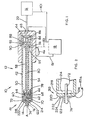
- a blind rivet setting system (10) comprises the rivet setting tool (12) for setting a blind rivet (14), a hydraulic intensifier (16) and system control circuit shown schematically as (18).
- the intensifier (16) may be any one of a number of conventional such intensifiers commonly used within the art but may simply be considered as a fluid pressure source for controllably applying pressure to the setting tool (12) by means of hydraulic fluid transferred via a fluid connection pipe (22).
- intensifiers (16) of this type employ a pressure source, such as pressurised air applied to a cylinder, to compress a hydraulic oil or fluid to transfer fluid pressure to the setting tool.
- the fluid contained in the intensifier (16) may be considered to be in continuous fluid communication, through pipe (22), with the rivet setting tool (12).
- the tool (12) comprises an elongated body generally illustrated as (42) which may be of any of several constructions but is preferably shown here provided with a handle (44).
- a trigger switch (46) which actuates to the tool (12) is fitted in the handle (44) in a conventional manner and is operatively associated with a valve (48).
- the tool (12) is further provided with an electronic control circuit (18) which is operatively connected, via wire (81) to the switch (46) such that actuation of the switch (46) will commence operation of the rivet setting cycle of the tool (12) in a conventional manner.
- the control circuit controls the operation of the associated valve (48) via control wire (91) and controls operation of the intensifier (16) via control wire (101) so that the rivet setting tool follows a predetermined setting cycle as will be described hereinafter.
- the elongated body (42) includes an elongated housing (50), which is sub divided internally into a front chamber (54) and a hydraulic cylinder chamber (56), wherein the elongated body (42) further includes an axially movable pulling shaft (58) provided along its longitudinally extending axis.
- the construction of the housing (50) is only one of a significant number of variations, where the only essential feature being that it provides support for the pulling shaft (58) and for a means of axially moving this shaft (58).
- a jaw assembly (60) is operatively associated with a front end of the pulling shaft (58).
- the jaw assembly (60) includes a jaw cage (62) having an internal bevelled wedging surface (64) that defines an internal bore (66).
- An array of split jaws (68) are movably provided within the cage (62). When the outer surfaces of the split jaw (68) act against the bevel surfaces (64), the jaws (68) engage and grip an elongated stem (70) of a mandrel (72) of a blind rivet (14).
- the mandrel (72) also includes a mandrel head (74).
- the mandrel (72) comprises the head forming component of the rivet (14) as is known in the art
- the rivet (14) includes a tubular deformable sleeve (76).
- a front end (41) of the housing (50) comprises a front end face (218) having a central aperture extending therethrough which is aligned coaxially with the axis A of the setting tool (12) which has an outwardly directed or front face (220) which is substantially perpendicular to the tool axis A, as is conventional for setting tools of this type and supports a flange (122) of the blind rivet (14) in a conventional manner and as shown in Figures 1 and Figures 2.
- the mandrel (72) will extend through the aperture in this front plate (218) and be received within the jaw assembly (60) in a conventional manner.
- This front plate (218) serves to prevent axial displacement of the deformable sleeve (76) of the rivet as the mandrel is drawn from left to right by operation of the setting tool.
- the setting tool (12) of the present invention differs from setting tools according to the prior art whereby a slot (214) extends transversely to the axis A through the front chamber (54) of the body (50) leaving a supporting bridge (216) (Figure 2) connecting front plate (218) to the rivet tool body (42) about a limited diameter of the body (50).
- the bridge section (216) may extend about up to 35% of the diameter of the body (50).
- the bridge (216) could alternatively comprise a plurality of fingers extending between the front plate and the body (50), such fingers again defining a maximum arc no greater than 35% of the diameter of the body. In this manner, the bridge (216) creates a cantilever with the front plate (218) as will be described later.
- a pusher (78) is fixed to the forward end of a pusher rod (80), which itself is housed within a central through bore defined in the pulling shaft (58).
- the pusher rod (80) is axially movable within this through bore and is biased, at this rear end, against the back wall of the hydraulic cylinder chamber (56) by a spring (84).
- a weaker spring (86) acts between the same wall and the rear end of the pulling shaft (58).
- a piston (88) is fixed to the pulling shaft (58) and is capable of axial motion in both forwards and rearwards direction within the hydraulic cylinder chamber (56).
- the hydraulic intensifier (16) forces a pressurised fluid (not shown) through the pipe (22) into the cylinder chamber (56) on the forwards side of the piston (88) through a pressurised fluid port (90) into a pressurisable side (92) of the hydraulic cylinder chamber (56).
- the piston (88) By introducing a pressurised fluid in the fluid-tight chamber defined within the pressurisable side (92), the piston (88) is forced to move rearwardly (from left to right as viewed in Figure 1), causing the jaw member (68) to clamp and apply a setting force to the mandrel stem (70) eventually causing it to break away from the mandrel head (74) as will be described below.
- blind rivets is derived from the fact that such rivets are installed from only one side of a workpiece or application, the primary side the blind rivet (14) includes the tubular rivet sleeve (76) having a flange (122) at its rear end as shown in Figure 1.
- the mandrel (72) has a stem (70) that passes through the tubular rivet body or sleeve (76) and has an enlarged mandrel head (74) formed at one end thereof.
- the mandrel stem is provided with a weakened portion which has a pre-determined breakpoint which will break when a sufficient load is applied. This is conventional within the field of blind rivet setting and need not be discussed in any great detail herein.
- the rivet (14) is loaded within the setting tool (12) as shown in Figure 1 and then introduced into a hole passing through an appropriate workpiece (not shown) such that the mandrel head and forward end of the sleeve (76) project through to the "blind side" of the workpiece.
- the mandrel stem (70) is then clamped between the split jaws (68) and is pulled by the setting tool (12).
- the head (74) of the rivet (14) is drawn into and enters the sleeve (76) as is conventional for setting of such blind rivets.
- This is denoted as the "mandrel entry point" and is the point at which the sleeve (76) begins to deform as the enlarged mandrel head is drawn therein.
- the pressure or load being exerted at this stage is referred to as the mandrel entry load.
- the rivet sleeve (76) is deformed up to the secondary or blind side of the workpiece being clamped and this deformed part of the sleeve (76) acts as secondary clamping element, whereas the flange (122) becomes the primary clamp element such that the workpieces are clamped therebetween. It is this combination of the secondary and primary clamp elements that hold two or more parts of an application or workpiece together.
- the fluid pressure within the chamber (56) is then released by releasing the setting tool trigger (46) and effecting appropriate control and displacement of the hydraulic intensifier (16), whereby both the pulling shaft (58) and the pusher rod (80) are restored to their pre-engaged positions by the biasing forces of the springs (84 and 86).
- the jaws (68) With the force of the jaws (68) removed, the jaws (68) are relaxed to their pre-engaged positions and the stem (70) is released and discarded.
- the tool (12) is then ready to repeat this rivet setting cycle.
- the setting tool (12) of Figure 1 is further shown comprising a conventional pressure transducer (99) mounted within the hydraulic cylinder chamber (56) for measuring the hydraulic fluid pressure applied to the piston (88) and provides an electrical output signal indicative of the pressure detected, via control wire (83) to be measured by the control circuit (18) which is able to convert such an output signal into a pressure measurement. Since the area of the piston (88) is constant this pressure measurement will then be indicative of the force being transmitted through the jaws to the mandrel stem (72). This is a conventional means of measuring the setting force being applied during the rivet setting operation.
- the system control circuit (18) will employ an appropriate conditioning circuit for converting an analogue signal to a digital signal which can then be passed through an appropriate amplifier circuit for monitoring the signal throughout the riveting cycle or, alternatively, sampling the transducer circuit at predetermined time intervals.
- the transducer (99) must be placed internally of the rivet setting tool (12) adding to the complex manufacturing process of assembling such a tool and making repairs or replacement of such measurement transducers.
- the improved load measuring means is shown, wherein a piezo-electric device can be utilised to directly measure the load applied to the blind rivet during the setting operation.
- the front end of the elongated body (42), in the region of the setting tool jaw assembly, (68), is provided with an additional slot (214) to form leave a supporting bridge (216) connecting the body (42) to the remote end plate (218) which engages and supports the rivet body flange (122) during the rivet setting operation (as shown).
- This supporting bridge (216) and end plate (218) create a cantilever which has mounted on its outwardly directed (or front face) (220) a piezo-electric thin film load indicating device (222) which is bonded by chemical bonding means such as an epoxy two part adhesive or a cyano-acryalate single part adhesive to be securely mounted thereon.
- a protective pad (224) is further bonded to the outer surface of the piezo-electric thin film load indicating device which protects the thin film load indicating device from mechanical damage by engagement with the rivet flange (122).
- the rivet mandrel stem (70) passes through a central co-axial aperture in the cantilevered end face (218), which aperture also extends co-axially through the piezo-electric device and the protective pad, so as to be engaged by the setting jaws (68) of the tool (210).
- the end face is now cantilevered as opposed to being rigidly supported on the elongate body (42).
- the resultant electric signal from the piezo-electric load indicating device (222) can then be analysed by the control circuit in a conventional manner to provide a direct output indicative of load being applied to the mandrel stem (72).
- Piezo-electric thin film load indicating devices are well understood in the art and comprise a variety of different designs.
- the piezo-electric thin film load indicating device may comprise a two-layer piezo-electric generator comprising a laminated two-layer element whereby when the applied mechanical force causes the cantilever to bend, the polarised two-layer element of the piezo-electric device also bends, whereby one layer is pressed and the other is stretched so that charge develops across each layer in an effort to counteract the imposed strains and it is this charge that is subsequently detected and analysed by the control circuit.
- the control circuit can subsequently be calibrated so as to analyse and convert the measured output signal of the piezo-electric device to produce an exact measurement of the load applied to the mandrel stem, or may simply output an uncalibrated signal which is indicative in the change of load applied during the rivet setting cycle.
- This uncalibrated signal will be of specific interest whereby the rivet setting procedure is analysed by consideration of the setting time between various peaks and troughs in a continuous load versus time measurement curve whereby this specific value of the applied load is not essential to determination of the quality of the set rivet.
- the load values are specifically required and thus it will be necessary to calibrate the control circuit accordingly.
- the load applied to the mandrel stem will initially increase until such time that the mandrel head exerts sufficient force to effect deformation of the cylindrical body of the rivet and is able to be drawn therein.
- the load exerted on the mandrel stem is reduced until such time that further resistance to the mandrel head displacement results from compression of the rivet body against the workpiece whereby there is a subsequent gradual increase in load on the rivet stem until the mandrel breaks in a conventional manner.
- loads are readily measured by the user of such piezo-electric thin film load measuring devices.
- This type of load measuring device has a specific beneficial application in monitoring a "free set" rivet setting operation whereby the rivet setting tool may inadvertently be operated remote from the workpiece so as to effectively set the rivet in free air.
- the load exerted on a rivet mandrel will increase gradually until such time that the mandrel head is drawn into the rivet body followed by a subsequent drop in determined load, resultant from the decreased resistance by the deforming rivet body.
- the deformed rivet body will engage the rear of a workpiece into which the rivet is being set, thereby preventing continued deformation and thus increasing resistance to displacement of the mandrel and an increase in the value of the load applied to the rivet by the setting tool until such time that the mandrel breaks and the applied load then rapidly decreases.
- load measurements produce a conventional load profile for the rivet and it has been determined that the time difference between the first load peak, (representative of the entry load value of the rivet), and the second, setting load peak, (equal to the load at which the mandrel breaks) remains substantially constant for a particular design of rivet when applied to a particular workpiece.
- the rivet setting time (the time taken until the mandrel is caused to break) will occur at a time period greater than that expected when the rivet is set in a known workpiece.
- the thin film load measuring devices as discussed above to measure a signal indicative of the load being applied to a mandrel and to analyse that signal as a function of time to determine the time difference between the two measured peaks of such a load curve will produce a time difference value which can be compared against a predetermined value (which is indicative of a acceptable setting procedure of a particular type of rivet in a known workpiece), to determine if the measured time difference is greater than the predetermined time difference.
- a predetermined value which is indicative of a acceptable setting procedure of a particular type of rivet in a known workpiece
- piezo-electric generators or sensors which do not operate in response to a bending operation but can, in fact, generate a suitable output voltage depending simply on the compressive force applied thereto.
- a conventional single layer piezo-electric generator such as a single sheet of piezo ceramic material
- a voltage is generated which tries to return the piezo-electric material to its original thickness. Again analysis of this generated voltage is indicative of the force being applied to such piezo-electric material.
- the front-end plate (218) could be maintained in rigid (non cantilevered) engagement with the front-end of the rivet setting tool (12) whereby such a single layer piezo-electric load generating device could then be mounted securely on the front face (220) of the tool to be compressed by the flange (122) of the rivet (in the manner previously discussed) to provide an output signal indicative of the load being exerted on the mandrel stem.
- the use of such piezo-electric materials to measure the setting load of this type of operation is measured directly from engagement with the rivet during the setting operation.
- the piezo-electric device is mounted externally of the rivet setting tool (12) it is readily accessible for repair or replacement as necessary thus providing an inexpensive and convenient load measuring device for mounting on an appropriate rivet setting tool.
Landscapes
- Engineering & Computer Science (AREA)
- Mechanical Engineering (AREA)
- Insertion Pins And Rivets (AREA)
- Force Measurement Appropriate To Specific Purposes (AREA)
- Curtains And Furnishings For Windows Or Doors (AREA)
- Portable Nailing Machines And Staplers (AREA)
- Toys (AREA)
Applications Claiming Priority (2)
| Application Number | Priority Date | Filing Date | Title |
|---|---|---|---|
| GB0216722A GB2390832B (en) | 2002-07-18 | 2002-07-18 | Improved blind fastener setting tool |
| GB0216722 | 2002-07-18 |
Publications (3)
| Publication Number | Publication Date |
|---|---|
| EP1382405A2 true EP1382405A2 (de) | 2004-01-21 |
| EP1382405A3 EP1382405A3 (de) | 2004-06-30 |
| EP1382405B1 EP1382405B1 (de) | 2006-07-05 |
Family
ID=9940721
Family Applications (1)
| Application Number | Title | Priority Date | Filing Date |
|---|---|---|---|
| EP03015921A Expired - Lifetime EP1382405B1 (de) | 2002-07-18 | 2003-07-12 | Nietsetzwerkzeug zum Setzen von Blindnieten |
Country Status (7)
| Country | Link |
|---|---|
| US (1) | US7055393B2 (de) |
| EP (1) | EP1382405B1 (de) |
| JP (1) | JP2004154860A (de) |
| AT (1) | ATE332200T1 (de) |
| DE (1) | DE60306587T2 (de) |
| ES (1) | ES2268231T3 (de) |
| GB (1) | GB2390832B (de) |
Families Citing this family (9)
| Publication number | Priority date | Publication date | Assignee | Title |
|---|---|---|---|---|
| GB2390833B (en) * | 2002-07-18 | 2005-09-14 | Emhart Llc | Method and apparatus for monitoring blind fastener setting |
| JP4842250B2 (ja) * | 2004-03-24 | 2011-12-21 | ニューフレイ リミテッド ライアビリティ カンパニー | リベット監視システム |
| US7802352B2 (en) * | 2005-04-13 | 2010-09-28 | Newfrey Llc | Monitoring system for fastener setting tool |
| JP4817807B2 (ja) * | 2005-11-07 | 2011-11-16 | シロキ工業株式会社 | ロータリーカシメ機、ロータリーカシメ方法 |
| ES2343987B1 (es) * | 2007-04-10 | 2011-06-13 | Airbus Operations, S.L. | Un metodo de verificacion dinamica de un proceso de remachado con remaches ciegos realizado con un aparato de remachado automatico, y dispositivo verificador para realizar la verificacion. |
| CN102527907B (zh) * | 2012-02-12 | 2013-11-20 | 深圳市君奕豪科技有限公司 | 一种用于抽芯铆钉的拉铆枪 |
| US11273931B2 (en) | 2018-09-24 | 2022-03-15 | The Boeing Company | Sensor based control of swage tools |
| US11052454B2 (en) * | 2019-07-23 | 2021-07-06 | The Boeing Company | Dynamic collar swage conformance checking based on swage tool parameters |
| EP4296004A1 (de) * | 2022-06-24 | 2023-12-27 | Bollhoff Otalu S.A. | Mundstück für eine setzvorrichtung, setzvorrichtung mit dem mundstück und verfahren zum setzen eines blindnietelements mit dem mundstück |
Citations (5)
| Publication number | Priority date | Publication date | Assignee | Title |
|---|---|---|---|---|
| DE4401134A1 (de) * | 1994-01-17 | 1995-07-27 | Infert Gmbh | Verfahren zur Überwachung der Verarbeitung von Blindbefestigern |
| EP0738551A2 (de) * | 1995-04-20 | 1996-10-23 | Emhart Inc. | Vorrichtung und Verfahren zur Überprüfung des Setzens von Blindnieten |
| EP0995518A2 (de) * | 1998-10-21 | 2000-04-26 | Emhart Inc. | Steuerung des Arbeitszyklus eines Nietwerkzeuges |
| US20010039718A1 (en) * | 1997-07-21 | 2001-11-15 | Dieter Mauer | Riveting system and process for forming a riveted joint |
| EP1382406A2 (de) * | 2002-07-18 | 2004-01-21 | Newfrey LLC | Verfahren und Vorrichtung zur Überwachung des Setzens von Blindnieten |
Family Cites Families (13)
| Publication number | Priority date | Publication date | Assignee | Title |
|---|---|---|---|---|
| US3772538A (en) * | 1973-01-08 | 1973-11-13 | Kane Corp Du | Center bolt type acoustic transducer |
| US4163311A (en) | 1977-02-28 | 1979-08-07 | Sps Technologies, Inc. | Tightening system for blind fasteners |
| JPS6034433B2 (ja) * | 1977-03-07 | 1985-08-08 | 株式会社豊田中央研究所 | 超音波変換器 |
| DE2855746C3 (de) * | 1978-12-22 | 1981-07-30 | Kistler Instrumente Ag, Winterthur | Piezoelektrischer Dehnungsaufnehmer |
| US5354160A (en) * | 1990-02-05 | 1994-10-11 | Textron Inc. | Composite fastener |
| US5323946A (en) | 1992-10-19 | 1994-06-28 | Emhart Inc. | Blind rivet setting tool |
| DE4401155C2 (de) | 1994-01-17 | 1998-02-26 | Infert Innovative Fertigungste | Verfahren zur Ermittlung von Kraftverläufen beim Nieten dünnwandiger Bauteile |
| DE4429225C2 (de) | 1994-08-18 | 1997-08-07 | Weber Schraubautomaten | Blindnietverfahren und -vorrichtung |
| US5666710A (en) | 1995-04-20 | 1997-09-16 | Emhart Inc. | Blind rivet setting system and method for setting a blind rivet then verifying the correctness of the set |
| US5841675A (en) | 1997-02-10 | 1998-11-24 | Oes, Inc. | Method and apparatus for monitoring quality of electrical wire connections |
| DE19731222C5 (de) | 1997-07-21 | 2016-10-13 | Newfrey Llc | Verfahren zum Ausbilden einer Stanznietverbindung sowie eine Fügevorrichtung für Stanzniete |
| EP1302258A1 (de) | 2001-10-11 | 2003-04-16 | Techspace Aero S.A. | Echzeitüberwachung der Qualität einer Nietverbindung |
| EP1469958B1 (de) | 2002-01-21 | 2008-12-03 | MS Gerätebau GmbH | Setzwerkzeug mit mitteln zur kontrolle von setzvorg ngen |
-
2002
- 2002-07-18 GB GB0216722A patent/GB2390832B/en not_active Revoked
-
2003
- 2003-07-12 DE DE60306587T patent/DE60306587T2/de not_active Expired - Lifetime
- 2003-07-12 AT AT03015921T patent/ATE332200T1/de not_active IP Right Cessation
- 2003-07-12 ES ES03015921T patent/ES2268231T3/es not_active Expired - Lifetime
- 2003-07-12 EP EP03015921A patent/EP1382405B1/de not_active Expired - Lifetime
- 2003-07-14 US US10/619,233 patent/US7055393B2/en not_active Expired - Fee Related
- 2003-07-17 JP JP2003198508A patent/JP2004154860A/ja active Pending
Patent Citations (5)
| Publication number | Priority date | Publication date | Assignee | Title |
|---|---|---|---|---|
| DE4401134A1 (de) * | 1994-01-17 | 1995-07-27 | Infert Gmbh | Verfahren zur Überwachung der Verarbeitung von Blindbefestigern |
| EP0738551A2 (de) * | 1995-04-20 | 1996-10-23 | Emhart Inc. | Vorrichtung und Verfahren zur Überprüfung des Setzens von Blindnieten |
| US20010039718A1 (en) * | 1997-07-21 | 2001-11-15 | Dieter Mauer | Riveting system and process for forming a riveted joint |
| EP0995518A2 (de) * | 1998-10-21 | 2000-04-26 | Emhart Inc. | Steuerung des Arbeitszyklus eines Nietwerkzeuges |
| EP1382406A2 (de) * | 2002-07-18 | 2004-01-21 | Newfrey LLC | Verfahren und Vorrichtung zur Überwachung des Setzens von Blindnieten |
Also Published As
| Publication number | Publication date |
|---|---|
| US7055393B2 (en) | 2006-06-06 |
| GB2390832B (en) | 2006-12-13 |
| DE60306587D1 (de) | 2006-08-17 |
| EP1382405A3 (de) | 2004-06-30 |
| ES2268231T3 (es) | 2007-03-16 |
| DE60306587T2 (de) | 2007-07-05 |
| JP2004154860A (ja) | 2004-06-03 |
| EP1382405B1 (de) | 2006-07-05 |
| GB0216722D0 (en) | 2002-08-28 |
| ATE332200T1 (de) | 2006-07-15 |
| GB2390832A (en) | 2004-01-21 |
| US20040060363A1 (en) | 2004-04-01 |
Similar Documents
| Publication | Publication Date | Title |
|---|---|---|
| EP1382406B1 (de) | Verfahren und Vorrichtung zur Überwachung des Setzens von Blindnieten | |
| JP3701733B2 (ja) | ブラインドリベット取付け確認装置及びその方法 | |
| JP4851065B2 (ja) | 取り付け動作を監視する手段を有する取り付け工具 | |
| US7503196B2 (en) | Rivet monitoring system | |
| JP3895800B2 (ja) | ブラインドリベット取付け装置及びブラインドリベット取付けと該取付けの正確さを確認する方法 | |
| US7346971B2 (en) | Blind rivet monitoring system supply pressure compensation | |
| JP2006289502A (ja) | ファスナ締結工具のための監視システム | |
| US7055393B2 (en) | Blind fastener setting tool | |
| JP5027134B2 (ja) | 締結具据付け工具用の監視システム | |
| US10307872B2 (en) | System and method for crimping a fastening component on a support | |
| US7313851B2 (en) | Method for monitoring the installation of blind rivets | |
| PL205309B1 (pl) | Narzędzie do osadzania ze środkami do kontroli operacji osadzania, głowica dla narzędzia do osadzania oraz sposób kontroli operacji osadzania, zwłaszcza operacji osadzania nitów, a także sposób kontroli nitu, zwłaszcza dla narzędzia do osadzania | |
| JPH0650862A (ja) | ブラインドリベットのリベット心棒の破断力を測定する方法 | |
| NO315189B1 (no) | Anordning og fremgangsmåte for anbringelse av et mekanisk fastholdelsesorgan og anvendelse av anordningen | |
| JPH0373402B2 (de) | ||
| KR20190015340A (ko) | 펄스 조임을 통한 클램프력 추정 | |
| US11740168B2 (en) | Quality inspection tool for projection welded fasteners | |
| CN117212294A (zh) | 一种超高压压力检测装置及方法 |
Legal Events
| Date | Code | Title | Description |
|---|---|---|---|
| PUAI | Public reference made under article 153(3) epc to a published international application that has entered the european phase |
Free format text: ORIGINAL CODE: 0009012 |
|
| AK | Designated contracting states |
Kind code of ref document: A2 Designated state(s): AT BE BG CH CY CZ DE DK EE ES FI FR GB GR HU IE IT LI LU MC NL PT RO SE SI SK TR |
|
| AX | Request for extension of the european patent |
Extension state: AL LT LV MK |
|
| RAP1 | Party data changed (applicant data changed or rights of an application transferred) |
Owner name: NEWFREY LLC |
|
| PUAL | Search report despatched |
Free format text: ORIGINAL CODE: 0009013 |
|
| AK | Designated contracting states |
Kind code of ref document: A3 Designated state(s): AT BE BG CH CY CZ DE DK EE ES FI FR GB GR HU IE IT LI LU MC NL PT RO SE SI SK TR |
|
| AX | Request for extension of the european patent |
Extension state: AL LT LV MK |
|
| RIC1 | Information provided on ipc code assigned before grant |
Ipc: 7B 21J 15/28 A Ipc: 7B 21J 15/06 B Ipc: 7B 21J 15/04 B |
|
| 17P | Request for examination filed |
Effective date: 20041217 |
|
| AKX | Designation fees paid |
Designated state(s): AT BE BG CH CY CZ DE DK EE ES FI FR GB GR HU IE IT LI LU MC NL PT RO SE SI SK TR |
|
| 17Q | First examination report despatched |
Effective date: 20050311 |
|
| GRAP | Despatch of communication of intention to grant a patent |
Free format text: ORIGINAL CODE: EPIDOSNIGR1 |
|
| GRAS | Grant fee paid |
Free format text: ORIGINAL CODE: EPIDOSNIGR3 |
|
| GRAA | (expected) grant |
Free format text: ORIGINAL CODE: 0009210 |
|
| AK | Designated contracting states |
Kind code of ref document: B1 Designated state(s): AT BE BG CH CY CZ DE DK EE ES FI FR GB GR HU IE IT LI LU MC NL PT RO SE SI SK TR |
|
| PG25 | Lapsed in a contracting state [announced via postgrant information from national office to epo] |
Ref country code: BE Free format text: LAPSE BECAUSE OF FAILURE TO SUBMIT A TRANSLATION OF THE DESCRIPTION OR TO PAY THE FEE WITHIN THE PRESCRIBED TIME-LIMIT Effective date: 20060705 Ref country code: AT Free format text: LAPSE BECAUSE OF FAILURE TO SUBMIT A TRANSLATION OF THE DESCRIPTION OR TO PAY THE FEE WITHIN THE PRESCRIBED TIME-LIMIT Effective date: 20060705 Ref country code: CH Free format text: LAPSE BECAUSE OF FAILURE TO SUBMIT A TRANSLATION OF THE DESCRIPTION OR TO PAY THE FEE WITHIN THE PRESCRIBED TIME-LIMIT Effective date: 20060705 Ref country code: FI Free format text: LAPSE BECAUSE OF FAILURE TO SUBMIT A TRANSLATION OF THE DESCRIPTION OR TO PAY THE FEE WITHIN THE PRESCRIBED TIME-LIMIT Effective date: 20060705 Ref country code: NL Free format text: LAPSE BECAUSE OF FAILURE TO SUBMIT A TRANSLATION OF THE DESCRIPTION OR TO PAY THE FEE WITHIN THE PRESCRIBED TIME-LIMIT Effective date: 20060705 Ref country code: LI Free format text: LAPSE BECAUSE OF FAILURE TO SUBMIT A TRANSLATION OF THE DESCRIPTION OR TO PAY THE FEE WITHIN THE PRESCRIBED TIME-LIMIT Effective date: 20060705 Ref country code: SK Free format text: LAPSE BECAUSE OF FAILURE TO SUBMIT A TRANSLATION OF THE DESCRIPTION OR TO PAY THE FEE WITHIN THE PRESCRIBED TIME-LIMIT Effective date: 20060705 Ref country code: SI Free format text: LAPSE BECAUSE OF FAILURE TO SUBMIT A TRANSLATION OF THE DESCRIPTION OR TO PAY THE FEE WITHIN THE PRESCRIBED TIME-LIMIT Effective date: 20060705 Ref country code: RO Free format text: LAPSE BECAUSE OF FAILURE TO SUBMIT A TRANSLATION OF THE DESCRIPTION OR TO PAY THE FEE WITHIN THE PRESCRIBED TIME-LIMIT Effective date: 20060705 |
|
| REG | Reference to a national code |
Ref country code: GB Ref legal event code: FG4D |
|
| PG25 | Lapsed in a contracting state [announced via postgrant information from national office to epo] |
Ref country code: IE Free format text: LAPSE BECAUSE OF NON-PAYMENT OF DUE FEES Effective date: 20060712 |
|
| REG | Reference to a national code |
Ref country code: CH Ref legal event code: EP |
|
| PG25 | Lapsed in a contracting state [announced via postgrant information from national office to epo] |
Ref country code: MC Free format text: LAPSE BECAUSE OF NON-PAYMENT OF DUE FEES Effective date: 20060731 |
|
| REG | Reference to a national code |
Ref country code: IE Ref legal event code: FG4D |
|
| REF | Corresponds to: |
Ref document number: 60306587 Country of ref document: DE Date of ref document: 20060817 Kind code of ref document: P |
|
| PG25 | Lapsed in a contracting state [announced via postgrant information from national office to epo] |
Ref country code: BG Free format text: LAPSE BECAUSE OF FAILURE TO SUBMIT A TRANSLATION OF THE DESCRIPTION OR TO PAY THE FEE WITHIN THE PRESCRIBED TIME-LIMIT Effective date: 20061005 Ref country code: DK Free format text: LAPSE BECAUSE OF FAILURE TO SUBMIT A TRANSLATION OF THE DESCRIPTION OR TO PAY THE FEE WITHIN THE PRESCRIBED TIME-LIMIT Effective date: 20061005 Ref country code: SE Free format text: LAPSE BECAUSE OF FAILURE TO SUBMIT A TRANSLATION OF THE DESCRIPTION OR TO PAY THE FEE WITHIN THE PRESCRIBED TIME-LIMIT Effective date: 20061005 |
|
| NLV1 | Nl: lapsed or annulled due to failure to fulfill the requirements of art. 29p and 29m of the patents act | ||
| PG25 | Lapsed in a contracting state [announced via postgrant information from national office to epo] |
Ref country code: PT Free format text: LAPSE BECAUSE OF FAILURE TO SUBMIT A TRANSLATION OF THE DESCRIPTION OR TO PAY THE FEE WITHIN THE PRESCRIBED TIME-LIMIT Effective date: 20061205 |
|
| ET | Fr: translation filed | ||
| REG | Reference to a national code |
Ref country code: ES Ref legal event code: FG2A Ref document number: 2268231 Country of ref document: ES Kind code of ref document: T3 |
|
| PLBE | No opposition filed within time limit |
Free format text: ORIGINAL CODE: 0009261 |
|
| STAA | Information on the status of an ep patent application or granted ep patent |
Free format text: STATUS: NO OPPOSITION FILED WITHIN TIME LIMIT |
|
| 26N | No opposition filed |
Effective date: 20070410 |
|
| PGFP | Annual fee paid to national office [announced via postgrant information from national office to epo] |
Ref country code: ES Payment date: 20070726 Year of fee payment: 5 |
|
| PG25 | Lapsed in a contracting state [announced via postgrant information from national office to epo] |
Ref country code: GR Free format text: LAPSE BECAUSE OF FAILURE TO SUBMIT A TRANSLATION OF THE DESCRIPTION OR TO PAY THE FEE WITHIN THE PRESCRIBED TIME-LIMIT Effective date: 20061006 |
|
| PG25 | Lapsed in a contracting state [announced via postgrant information from national office to epo] |
Ref country code: EE Free format text: LAPSE BECAUSE OF FAILURE TO SUBMIT A TRANSLATION OF THE DESCRIPTION OR TO PAY THE FEE WITHIN THE PRESCRIBED TIME-LIMIT Effective date: 20060705 |
|
| PG25 | Lapsed in a contracting state [announced via postgrant information from national office to epo] |
Ref country code: HU Free format text: LAPSE BECAUSE OF FAILURE TO SUBMIT A TRANSLATION OF THE DESCRIPTION OR TO PAY THE FEE WITHIN THE PRESCRIBED TIME-LIMIT Effective date: 20070106 Ref country code: LU Free format text: LAPSE BECAUSE OF NON-PAYMENT OF DUE FEES Effective date: 20060712 Ref country code: TR Free format text: LAPSE BECAUSE OF FAILURE TO SUBMIT A TRANSLATION OF THE DESCRIPTION OR TO PAY THE FEE WITHIN THE PRESCRIBED TIME-LIMIT Effective date: 20060705 |
|
| PG25 | Lapsed in a contracting state [announced via postgrant information from national office to epo] |
Ref country code: CY Free format text: LAPSE BECAUSE OF FAILURE TO SUBMIT A TRANSLATION OF THE DESCRIPTION OR TO PAY THE FEE WITHIN THE PRESCRIBED TIME-LIMIT Effective date: 20060705 |
|
| REG | Reference to a national code |
Ref country code: ES Ref legal event code: FD2A Effective date: 20080714 |
|
| PG25 | Lapsed in a contracting state [announced via postgrant information from national office to epo] |
Ref country code: ES Free format text: LAPSE BECAUSE OF NON-PAYMENT OF DUE FEES Effective date: 20080714 |
|
| PGFP | Annual fee paid to national office [announced via postgrant information from national office to epo] |
Ref country code: CZ Payment date: 20090630 Year of fee payment: 7 |
|
| PGFP | Annual fee paid to national office [announced via postgrant information from national office to epo] |
Ref country code: DE Payment date: 20100728 Year of fee payment: 8 Ref country code: FR Payment date: 20100805 Year of fee payment: 8 Ref country code: IT Payment date: 20100723 Year of fee payment: 8 |
|
| PGFP | Annual fee paid to national office [announced via postgrant information from national office to epo] |
Ref country code: GB Payment date: 20100726 Year of fee payment: 8 |
|
| PG25 | Lapsed in a contracting state [announced via postgrant information from national office to epo] |
Ref country code: CZ Free format text: LAPSE BECAUSE OF NON-PAYMENT OF DUE FEES Effective date: 20100712 |
|
| GBPC | Gb: european patent ceased through non-payment of renewal fee |
Effective date: 20110712 |
|
| REG | Reference to a national code |
Ref country code: FR Ref legal event code: ST Effective date: 20120330 |
|
| PG25 | Lapsed in a contracting state [announced via postgrant information from national office to epo] |
Ref country code: DE Free format text: LAPSE BECAUSE OF NON-PAYMENT OF DUE FEES Effective date: 20120201 Ref country code: FR Free format text: LAPSE BECAUSE OF NON-PAYMENT OF DUE FEES Effective date: 20110801 |
|
| REG | Reference to a national code |
Ref country code: DE Ref legal event code: R119 Ref document number: 60306587 Country of ref document: DE Effective date: 20120201 |
|
| PG25 | Lapsed in a contracting state [announced via postgrant information from national office to epo] |
Ref country code: IT Free format text: LAPSE BECAUSE OF NON-PAYMENT OF DUE FEES Effective date: 20110712 |
|
| PG25 | Lapsed in a contracting state [announced via postgrant information from national office to epo] |
Ref country code: GB Free format text: LAPSE BECAUSE OF NON-PAYMENT OF DUE FEES Effective date: 20110712 |