EP1380905A2 - Elektromechanische Schaltuhr - Google Patents
Elektromechanische Schaltuhr Download PDFInfo
- Publication number
- EP1380905A2 EP1380905A2 EP03014666A EP03014666A EP1380905A2 EP 1380905 A2 EP1380905 A2 EP 1380905A2 EP 03014666 A EP03014666 A EP 03014666A EP 03014666 A EP03014666 A EP 03014666A EP 1380905 A2 EP1380905 A2 EP 1380905A2
- Authority
- EP
- European Patent Office
- Prior art keywords
- ring
- display element
- switching
- switching ring
- program
- Prior art date
- Legal status (The legal status is an assumption and is not a legal conclusion. Google has not performed a legal analysis and makes no representation as to the accuracy of the status listed.)
- Withdrawn
Links
- 230000008878 coupling Effects 0.000 claims description 7
- 238000010168 coupling process Methods 0.000 claims description 7
- 238000005859 coupling reaction Methods 0.000 claims description 7
- 238000007373 indentation Methods 0.000 claims description 6
- 238000011161 development Methods 0.000 description 2
- 230000018109 developmental process Effects 0.000 description 2
- 238000010276 construction Methods 0.000 description 1
- 230000001419 dependent effect Effects 0.000 description 1
Images

Classifications
-
- G—PHYSICS
- G04—HOROLOGY
- G04C—ELECTROMECHANICAL CLOCKS OR WATCHES
- G04C23/00—Clocks with attached or built-in means operating any device at preselected times or after preselected time-intervals
Definitions
- the invention relates to an electromechanical timer according to the preamble of claim 1.
- timers have been known for a long time.
- To display the set Operating status (“continuously on”, “automatic operation” or “continuously off”) these timers each have an operating button on their switching rings, which has a mark.
- This marking works with display symbols together, which are mounted on a front panel, in which the time switch is installed.
- An electromechanical timer is known from EP 0 409 935 B1, at which is the switching device for setting the various operating states is arranged within the program ring. At the position of the actuator this switching device shows which operating state is set. So here are both the switching device and the display of the set Operating state arranged within the program ring.
- the present Invention the object of the generic electromechanical To further develop the timer so that the display of the set Operating state regardless of the use of a control front, in which the timer is installed, is possible.
- the display device has first and second display element, the first stationary and the second is rotatable.
- the second display element is one turn of the switching ring coupled. This is preferably done by a Coupling element, which the rotation of the switching ring on the second Display element transmits.
- This coupling element preferably has two Indentations on, with the first one rotatably with the switching ring connected pin and in the second one with the second display element engages rotatably connected pin.
- the second Display element is designed as a circle, which within the as a ring executed first display element is arranged.
- the switching ring can be part of a switching housing, which next to the Switching ring also has a switching disc.
- a time switch 1 according to the prior art (see FIG. 1) has one Program ring 2, which of an (not shown) electric motor is driven and circulates in a time-keeping manner, whereby it rotates around 360 in 24 hours Degrees rotates.
- the program ring 2 carries program tab 3 with which the Program sequence of the timer can be set.
- the program riders in an external position (3.1), the connected consumer is not included Power supplied.
- the program tabs are in an inner position (3.2), so the connected consumer at the appropriate times switched on.
- a switching ring 4 is arranged concentrically outside the program ring 3, which can be turned into three positions, depending on the operating conditions correspond to "permanently on”, “automatic mode” and “continuously off”.
- the Switch ring 4 carries an actuating button 5, on which a mark is attached is. This marking interacts with symbols 6.1, 6.2 and 6.3, which on a control panel 7 are printed, in the recess 8 the time switch 1 is mounted.
- the mark on the operating button 5 forms with the on the Control panel 7 applied symbols 6.1, 6.2 and 6.3 one Operating status display.
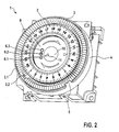
- a timer 1 according to the invention also has one Switching ring 4 with actuating button 5, which is outside the program ring 2 is arranged concentrically around this.
- this points Timer 1 still has a first display element 9, which is stationary, i.e. H. not rotatably arranged within the program ring 2 and designed as a ring is.
- This first display element carries u. a. Symbols 6.1, 6.2 and 6.3.
- a second display element 10 arranged, which carries a mark 11 and is rotatable.
- the second display element 10 is coupled to the switching ring 4 such that a Rotation of the switching ring 4 is transmitted to the second display element 10 and the mark 11 on the second display element 10 each on that Symbol 6.1, 6.2 or 6.3 shows that the one just set with the switching ring 4 Operating condition corresponds.
- the first and the second display element thus form 9 and 10 together with the symbols 6.1, 6.2 and 6.3 and the marking 11 an operating status display for the time switch 1.
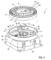
- the switching ring 4 is part of a switch housing 12, which consists of just that Switch ring 4 and a switching disc 13 is made.
- the switching disc 13 has one Recess 14 for a gear 15 for driving the program disk 2, a Recess 16 for the passage of the switching elements, recesses 17 and 18 for the attack of guide bolts 19 and a pin 20.
- the cone 20 engages in an indentation 21 of a coupling element 22 which is rotatably mounted on the timer housing 23.
- the coupling element 22 also has a second indentation 24 into which a pin 25 engages, which is attached to the second display element 10.
- the second too Display element 10 is rotatably mounted on the timer housing 23.
- the invention enables the user to determine the operating states of the time switch conveniently with the switching ring 4 arranged outside the program ring 2 (possibly via the operating button 5) and at the same time via a Display device arranged within the program ring 2 each read the set operating status.
Landscapes
- Physics & Mathematics (AREA)
- General Physics & Mathematics (AREA)
- Measurement Of Predetermined Time Intervals (AREA)
- Electromechanical Clocks (AREA)
Abstract
Description
- Figur 1
- eine Schaltuhr nach dem Stand der Technik in perspektivischer Darstellung,
- Figur 2
- eine erfindungsgemäße Schaltuhr in perspektivischer Darstellung und
- Figur 3
- die erfindungsgemäße Schaltuhr in Explosionsdarstellung.
Claims (7)
- Elektromechanische Schaltuhr (1) mit einem zeithaltend umlaufenden Programmring (2) und mit einem außerhalb des Programmringes (2) und konzentrisch zu diesem angeordneten Schaltring (4) zur Einstellung der Betriebszustände der Schaltuhr (1),
dadurch gekennzeichnet, dass innerhalb des Programmringes (2) eine mit dem Schaltring (4) wirkverbundene Anzeigeeinrichtung zur Anzeige des mit dem Schaltring (4) eingestellten Betriebszustandes angeordnet ist. - Elektromechanische Schaltuhr nach Anspruch 1,
dadurch gekennzeichnet, dass die Anzeigeeinrichtung ein erstes und ein zweites Anzeigeelement (9, 10) aufweist, wobei das erste Anzeigeelement (9) ortsfest und das zweite Anzeigeelement (10) drehbar ausgeführt ist. - Elektromechanische Schaltuhr nach Anspruch 2,
dadurch gekennzeichnet, dass das zweite, drehbar ausgeführte Anzeigeelement (10) derart mit dem Schaltring (4) wirkverbunden ist, dass es sich bei einer Drehung des Schaltringes (4) ebenfalls dreht. - Elektromechanische Schaltuhr nach Anspruch 3,
dadurch gekennzeichnet, dass die Wirkverbindung des zweiten Anzeigeelementes (10) mit dem Schaltring (4) durch ein Kopplungselement (22) gebildet ist, welches derart ausgeführt ist, dass es eine Drehung des Schaltringes (4) in eine Drehung des zweiten Anzeigeelementes (10) überträgt. - Elektromechanische Schaltuhr nach Anspruch 4,
dadurch gekennzeichnet, dass das Kopplungselement (22) eine erste und eine zweite Einbuchtung (21, 24) aufweist, wobei in die erste Einbuchtung (21) ein mit dem Schaltring (4) drehfest verbundener Zapfen (20) eingreift und in die zweite Einbuchtung (24) ein mit dem zweiten Anzeigeelement (10) drehfest verbundener Zapfen (25) eingreift. - Elektromechanische Schaltuhr nach einem der Ansprüche 2 bis 5,
dadurch gekennzeichnet, dass das zweite Anzeigeelement (10) als Kreis und das erste Anzeigeelement (9) als Ring ausgeführt sind, wobei das zweite Anzeigeelement (10) innerhalb des ersten Anzeigeelements (9) angeordnet ist. - Elektromechanische Schaltuhr nach einem der vorherigen Ansprüche,
dadurch gekennzeichnet, dass der Schaltring (4) Teil eines eine Schaltscheibe (13) aufweisenden Schaltgehäuses (12) ist.
Applications Claiming Priority (2)
| Application Number | Priority Date | Filing Date | Title |
|---|---|---|---|
| DE2002130454 DE10230454A1 (de) | 2002-07-06 | 2002-07-06 | Elektromechanische Schaltuhr |
| DE10230454 | 2002-07-06 |
Publications (2)
| Publication Number | Publication Date |
|---|---|
| EP1380905A2 true EP1380905A2 (de) | 2004-01-14 |
| EP1380905A3 EP1380905A3 (de) | 2005-02-02 |
Family
ID=29723746
Family Applications (1)
| Application Number | Title | Priority Date | Filing Date |
|---|---|---|---|
| EP03014666A Withdrawn EP1380905A3 (de) | 2002-07-06 | 2003-06-27 | Elektromechanische Schaltuhr |
Country Status (2)
| Country | Link |
|---|---|
| EP (1) | EP1380905A3 (de) |
| DE (1) | DE10230454A1 (de) |
Family Cites Families (4)
| Publication number | Priority date | Publication date | Assignee | Title |
|---|---|---|---|---|
| EP0409935B1 (de) * | 1989-02-04 | 1994-09-28 | Grässlin Kg | Elektromechanische schaltuhr |
| DE8911155U1 (de) * | 1989-09-19 | 1991-01-24 | Diehl GmbH & Co, 8500 Nürnberg | Schalter für einen Schaltuhrmodul |
| DE29720429U1 (de) * | 1997-11-19 | 1998-04-02 | Grässlin KG, 78112 St Georgen | Programmierungsvorrichtung für analog anzeigende elektromechanische oder elektronische Schalt- und/oder Regelgeräte |
| EP1098336B1 (de) * | 1999-11-05 | 2001-05-30 | Orbis Tecnologia Eléctrica S.A. | Elektrische Schaltuhr |
-
2002
- 2002-07-06 DE DE2002130454 patent/DE10230454A1/de not_active Ceased
-
2003
- 2003-06-27 EP EP03014666A patent/EP1380905A3/de not_active Withdrawn
Also Published As
| Publication number | Publication date |
|---|---|
| EP1380905A3 (de) | 2005-02-02 |
| DE10230454A1 (de) | 2004-01-22 |
Similar Documents
| Publication | Publication Date | Title |
|---|---|---|
| DE3028812C2 (de) | Schalter mit Mitteln zur fernbetätigten Ein- und Ausschaltung | |
| EP0963592B1 (de) | Motorantrieb | |
| DE3131147C2 (de) | ||
| DE3941352C2 (de) | Elektromotorisches Stellglied | |
| DE2619298C3 (de) | Datumskorrekturmechanismus für eine Uhr | |
| DE4420582C2 (de) | Einfahrbares Schaltgerät mit einer Anzeigevorrichtung für die Stellung des Schaltgerätes | |
| DE102017215656B4 (de) | Stellungsanzeiger sowie damit ausgestatteter Drehantrieb und Prozessventil | |
| DE2514842A1 (de) | Weckerwerk | |
| DE2835518C2 (de) | Elektrische Schaltuhr mit analoger Uhrzeitanzeige | |
| EP0518100B1 (de) | Stellantrieb | |
| EP1380905A2 (de) | Elektromechanische Schaltuhr | |
| DE10136418B4 (de) | Kamera mit einer Einstellrad/Anzeigefeld-Einheit | |
| DE3325588C2 (de) | Schaltuhr mit einer sich drehenden Programmscheibe | |
| AT396283B (de) | Betaetigungsvorrichtung fuer die endlagenschaltvorrichtung einer elektromotorisch angetriebenen jalousie | |
| DE3734502C2 (de) | ||
| DE7600670U1 (de) | Laboruhr | |
| DE69721741T2 (de) | Kupplungsmechanismus in einem Uhrwerkzahnradgetriebe | |
| DE1591284C (de) | Kombinierte VHF UHF Abstimmvornch tung | |
| DE423247C (de) | Vorrichtung zur Verschiebung des Schlittens an Rechenmaschinen | |
| DE404845C (de) | Fahrtrichtungsanzeiger fuer Fahrzeuge, insbesondere Kraftfahrzeuge, mit durch Eindruecken von Knoepfen oder Wellen betaetigtem Schaltwerk zum Schliessen eines Signalstromkreises, der selbsttaetig wieder ausgeschaltet wird | |
| EP0951726A1 (de) | Endschaltervorrichtung | |
| DE102007038202B3 (de) | 24-Stunden-Anzeige für eine Uhr mit Zeigern | |
| DE3202689C2 (de) | ||
| EP1235001A2 (de) | Drehbarer Stellantrieb | |
| DE4125548A1 (de) | Licht- und farbintensitaets-messgeraet |
Legal Events
| Date | Code | Title | Description |
|---|---|---|---|
| PUAI | Public reference made under article 153(3) epc to a published international application that has entered the european phase |
Free format text: ORIGINAL CODE: 0009012 |
|
| AK | Designated contracting states |
Kind code of ref document: A2 Designated state(s): AT BE BG CH CY CZ DE DK EE ES FI FR GB GR HU IE IT LI LU MC NL PT RO SE SI SK TR |
|
| AX | Request for extension of the european patent |
Extension state: AL LT LV MK |
|
| PUAL | Search report despatched |
Free format text: ORIGINAL CODE: 0009013 |
|
| AK | Designated contracting states |
Kind code of ref document: A3 Designated state(s): AT BE BG CH CY CZ DE DK EE ES FI FR GB GR HU IE IT LI LU MC NL PT RO SE SI SK TR |
|
| AX | Request for extension of the european patent |
Extension state: AL LT LV MK |
|
| RIC1 | Information provided on ipc code assigned before grant |
Ipc: 7H 01H 43/02 B Ipc: 7G 04C 23/00 A |
|
| AKX | Designation fees paid | ||
| REG | Reference to a national code |
Ref country code: DE Ref legal event code: 8566 |
|
| STAA | Information on the status of an ep patent application or granted ep patent |
Free format text: STATUS: THE APPLICATION IS DEEMED TO BE WITHDRAWN |
|
| 18D | Application deemed to be withdrawn |
Effective date: 20050803 |