EP1380766A2 - Hydrodynamische Maschine - Google Patents
Hydrodynamische Maschine Download PDFInfo
- Publication number
- EP1380766A2 EP1380766A2 EP03015083A EP03015083A EP1380766A2 EP 1380766 A2 EP1380766 A2 EP 1380766A2 EP 03015083 A EP03015083 A EP 03015083A EP 03015083 A EP03015083 A EP 03015083A EP 1380766 A2 EP1380766 A2 EP 1380766A2
- Authority
- EP
- European Patent Office
- Prior art keywords
- blade
- recess
- stator
- hydrodynamic machine
- wheel
- Prior art date
- Legal status (The legal status is an assumption and is not a legal conclusion. Google has not performed a legal analysis and makes no representation as to the accuracy of the status listed.)
- Withdrawn
Links
- 239000012530 fluid Substances 0.000 description 3
- 230000009467 reduction Effects 0.000 description 3
- 239000007788 liquid Substances 0.000 description 2
- 230000009471 action Effects 0.000 description 1
- 230000005540 biological transmission Effects 0.000 description 1
- 239000002775 capsule Substances 0.000 description 1
- 238000001816 cooling Methods 0.000 description 1
- 230000008878 coupling Effects 0.000 description 1
- 238000010168 coupling process Methods 0.000 description 1
- 238000005859 coupling reaction Methods 0.000 description 1
- 230000005284 excitation Effects 0.000 description 1
- 238000009413 insulation Methods 0.000 description 1
- 238000000034 method Methods 0.000 description 1
- 230000008569 process Effects 0.000 description 1
- 230000000284 resting effect Effects 0.000 description 1
- 239000007787 solid Substances 0.000 description 1
- 230000007704 transition Effects 0.000 description 1
Images





Classifications
-
- F—MECHANICAL ENGINEERING; LIGHTING; HEATING; WEAPONS; BLASTING
- F16—ENGINEERING ELEMENTS AND UNITS; GENERAL MEASURES FOR PRODUCING AND MAINTAINING EFFECTIVE FUNCTIONING OF MACHINES OR INSTALLATIONS; THERMAL INSULATION IN GENERAL
- F16D—COUPLINGS FOR TRANSMITTING ROTATION; CLUTCHES; BRAKES
- F16D57/00—Liquid-resistance brakes; Brakes using the internal friction of fluids or fluid-like media, e.g. powders
- F16D57/005—Details of blades, e.g. shape
-
- F—MECHANICAL ENGINEERING; LIGHTING; HEATING; WEAPONS; BLASTING
- F16—ENGINEERING ELEMENTS AND UNITS; GENERAL MEASURES FOR PRODUCING AND MAINTAINING EFFECTIVE FUNCTIONING OF MACHINES OR INSTALLATIONS; THERMAL INSULATION IN GENERAL
- F16D—COUPLINGS FOR TRANSMITTING ROTATION; CLUTCHES; BRAKES
- F16D33/00—Rotary fluid couplings or clutches of the hydrokinetic type
- F16D33/18—Details
- F16D33/20—Shape of wheels, blades, or channels with respect to function
-
- F—MECHANICAL ENGINEERING; LIGHTING; HEATING; WEAPONS; BLASTING
- F16—ENGINEERING ELEMENTS AND UNITS; GENERAL MEASURES FOR PRODUCING AND MAINTAINING EFFECTIVE FUNCTIONING OF MACHINES OR INSTALLATIONS; THERMAL INSULATION IN GENERAL
- F16D—COUPLINGS FOR TRANSMITTING ROTATION; CLUTCHES; BRAKES
- F16D57/00—Liquid-resistance brakes; Brakes using the internal friction of fluids or fluid-like media, e.g. powders
- F16D57/04—Liquid-resistance brakes; Brakes using the internal friction of fluids or fluid-like media, e.g. powders with blades causing a directed flow, e.g. Föttinger type
-
- F—MECHANICAL ENGINEERING; LIGHTING; HEATING; WEAPONS; BLASTING
- F16—ENGINEERING ELEMENTS AND UNITS; GENERAL MEASURES FOR PRODUCING AND MAINTAINING EFFECTIVE FUNCTIONING OF MACHINES OR INSTALLATIONS; THERMAL INSULATION IN GENERAL
- F16D—COUPLINGS FOR TRANSMITTING ROTATION; CLUTCHES; BRAKES
- F16D65/00—Parts or details
- F16D65/0006—Noise or vibration control
Definitions
- the invention relates to a hydrodynamic machine according to the preamble of claim 1.
- the unsteady hydrodynamic states in one hydrodynamic machine in connection with the high load of the components call in connection with the complete Medium supply and discharge through the flow processes noise emerged, which are both fluid and solid as airborne sound and in different Areas of application, for example in vehicles in Road traffic are undesirable.
- the first option is secondary sound insulation measures by encapsulating the unit.
- the second option consists in reducing the sound at the excitation point. Against secondary measures, for example in an arrangement of insulating capsules, speak in addition to the costs, the assembly effort and the additional space required the obstruction of convection. These measures are therefore disadvantageous and reject.
- EP 0 634 584 B1 describes a hydrodynamic retarder became known in which primary noise reduction measures were carried out. To reduce noise were suggested in this retarder, the number the blades of the rotor blade wheel to be higher than the number of blades of the stator impeller. This too Action does not lead to the desired success and is too improve.
- the present invention is based on the object noise reduction on hydrodynamic machines improve.
- a hydrodynamic machine has a housing that comprises at least one rotor blade wheel and one stator blade wheel.
- the rotor blade wheel and the stator blade wheel each have a number of blades.
- Recesses are provided on all blades of at least one of the mentioned wheels, that is to say at least the rotor blade wheel or at least the stator blade wheel, in order to reduce the development of noise.
- the blade edge is withdrawn with respect to an imaginary line between the radially outer component edge and the radially inner component edge of the rotor blade wheel or stator blade wheel.
- the cutouts are designed in such a way that on all blades of at least the rotor blade wheel or at least the stator blade wheel the projected blade surface of the blade, that is to say the surface of the blade shown in a plan view, is reduced compared to the projected surface of an at least largely semicircular blade. If a blade is referred to in succession, what has been said applies to all blades on the respective component, with the result that all blades on a component are of identical design with regard to the cutouts.
- the blade is designed such that it has a recess on its radially outer part on the blade edge. In a further embodiment, the blade has a recess on its radially inner part of the blade edge.
- the recess in the form of a segment of a circle at an angle of 0 to 30 ° with respect to the blade edge, the angle preferably being 8 °.
- two circular segments with different angles overlap to form the recess.
- the blade is designed such that the blade has a cutout in the central region of its radial extension at the edge of the blade.
- the cutout in the middle area can extend over the entire length of the blade edge.
- the cutout preferably has a trapezoidal configuration in the central region.
- the trapezoidal configuration is such that the corners that are not on the blade edge are rounded.
- the trapezoidal configuration comprises a right-angled trapezoid.
- Embodiments are particularly advantageous in which the cutouts in the radially inner part of the blade edge, the cutouts in the radially outer part of the blade edge and the cutouts in the central region of the radial extent on the blade edge are mutually overlapping.
- One embodiment shows the recesses on the blades of the rotor impeller, one embodiment shows the recesses on the blades of the stator impeller.
- a configuration is particularly advantageous in which cutouts are provided both in the blades of the rotor blade wheel and in the blades of the stator blade wheel and the cutouts on the blades of the rotor blade wheel and on the blades of the stator blade wheel are different.
- the at least one rotor blade wheel and the at least one stator blade wheel are preferably used as the rotor and stator blade wheel of a hydrodynamic retarder for wear-free braking of a vehicle in road traffic.
- the function of the hydrodynamic machine is determined by the changes made are not affected. Especially the required braking torque of a retarder, the Cooling volume flow and the pressure conditions are not deteriorated.
- the momentum of the hydrodynamic fluid becomes Transition from rotating to resting or less quickly rotating component or from stationary to rotating or reduced rotating component. This diminution causes noise reduction.
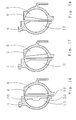
- FIG. 1 shows in a sectional view as one Section from a retarder 2 as a hydrodynamic Machine a stator impeller 4 fixed to the housing and opposite the stator impeller 4 rotatable rotor impeller 6.
- the rotor blade 8 on the rotor blade wheel 6 is like completely semicircular known from the prior art trained and has no recesses here.
- the blade edge 14 is opposite this recess 12 a line 20 between the radially outer Component edge 16 and the radially inner component edge 18 withdrawn.
- the rotor blade 8 corresponds to the rotor blade according to Fig. 1.
- the stator blade 10 of the stator impeller 4 also has a recess 30 in the form of a circular segment or semi-circular segment intended.
- the rotor blade 8 has a recess 22, the withdrawn blade edge 24 only in part of a imaginary line 32 between the radially outside here Component edge 26 and the radially inner component edge 28 is withdrawn and the recess 22 from the Line 32 from at an angle ⁇ of, for example, 30 ° opens.
- the stator blade 10 initially has a recess 30 in accordance with FIG.
- This recess 30 is covered by a second recess 34, which is from line 32 at an angle ⁇ of, for example 30 ° opens.
- the rotor blade 8 has a Recess 30 in accordance with FIG. 2.
- the stator blade 10 has its radial extent in the central region a trapezoidal recess 36.
- the one on the edge of the bucket opposite baseline of the trapezoid Corners 38 are rounded.
- Two angles 40 the trapezoidal recess 36 are rectangular. 5
- the blade edge 14 is on the stator blade 10 withdrawn along their entire length by the same amount. Therefore, the recess 42 has an almost rectangular shape.
- the rotor blade 8 has a covered one Recess 44 in which two segments with different Overlap angles.
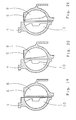
- 6 shows recesses with segment-shaped Training both on the rotor blade 8 and on the stator blade 10.
- the cutout on the stator blade has two overlapping segments, the Angle of the segments in opposite directions to open.
- 7 shows an overlap of a recess 42 of FIG. 5 on the stator blade 10 with a recess 36 according to FIG. 4.
- the rotor blade 8 has a simple one 5 without overlap.
- the 8 shows an overlap of a on the stator blade 10 Recess 42 and a recess 36 according to FIGS.
- the rotor blade 8 has a recess corresponding to the recess 44 according to FIG. 7 48, whose angle, however, is external to the rotor blade wheel opens.
- 9 shows a stator blade 10 with an overlap of two segment-shaped recesses 6, which is still of a recess is covered according to the recess 36 of FIG. 4. No recess is provided on the rotor blade 8 here.
- 10 shows one of two on the rotor blade 8 recess formed corresponding covering segments 6, but here is formed with opposite angles.
- the Stator blade 10 has no recess here.
- the 11 shows a stator blade 10 with a recess, which is made up of two overlapping segments, whose different angles are in the same direction open radially outwards and are still covered by a trapezoidal recess corresponding to recess 36 according to Fig. 4.
- the recess on the rotor blade 8 is here formed from two overlapping segments, their different Angle in the same direction open radially inside.
- the recess is on the stator blade 10 formed by an overlap one segment-shaped recess, the angle of which is radial the outside opens accordingly with a trapezoidal recess the recess 36 in FIG. 4.
- On the rotor blade 8 is a simple recess corresponding to the recess 22 provided on FIG. 3.
- the stator blade 10 has a trapezoidal recess correspond to the recess 36 according to FIG. 4.
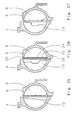
- the recess has two overlapping segments on the rotor blade 8 according to the recess on the rotor blade 11, other angles being selected here.
- the stator blade 10 has a reset Circle segment as a recess, that of the recess 44 corresponds to the rotor blade 8 according to FIG. 7, the angle here opens radially outwards.
- the recess the rotor blade 10 is formed from a recess accordingly the recess 42 on the stator blade 10 according to Fig. 5, which is covered by a segment-shaped recess corresponding to the recess 22 of Fig. 3.
- Die 15 shows a recess on the stator blade 10 corresponding the overlap of the recesses 36 and 42 Fig. 7.
- the recess on the rotor blade 8 corresponds the recess on the rotor blade 8 in FIG. 10 with in contrast, changed angle values.
- the recess on the The rotor blade 8 in FIG. 16 corresponds to the recess the rotor blade 8 according to FIG. 14 with a changed angle and changed value for the withdrawn rotor blade edge.
- the recess on the stator blade 10 is formed corresponding to a recess in the stator blade 10 in Fig.
- stator blade 10 On the stator blade 10 is the recess formed from the overlap according to the recess 42 from FIG. 5 and according to the segment-shaped recess 46 in FIG. 8.
- the stator blade has 10 a segment-shaped recess according to the recess 46 according to FIG. 8.
- the rotor blade 8 In the rotor blade 8 is one Recess according to the recess 30 provided in FIG. 4. 19 has no recess in the rotor blade 8 on.
- the recess in the stator blade 10 corresponds to the Recess in the stator blade 10 according to FIG.
- FIG. 20 is the Recess of the stator blade 10 formed similar to that Recess in the stator blade 10 according to FIG. 9. Also here are other angles of the segmented recesses intended.
- the recess in the rotor blade 8 corresponds with partially changed angles of the recess in the rotor blade 8 of Fig. 11.
- the recess of the stator blade 10 in FIG. 21 corresponds to FIG. 8. Similar to that The recess in the rotor blade 8 in FIG. 5 is here the configuration of the recess in the rotor blade 8 intended.
- a segment-shaped Recess in the radially outer part of the stator blade 10 still a trapezoidal recess in the radial middle Area of the stator blade 10 is provided. An overlap There are no gaps here, but that Recesses are almost adjacent.
- the shape of the rotor blade 8 corresponds to the rotor blade known from FIG. 10 8.
- Fig. 23 is a shape of the stator blade 10 used according to FIG. 20. With changed angles the recess of the rotor blade 8 corresponds to the rotor blade recess according to Fig. 10.
- Fig. 24 is one small segment-shaped recess in the stator impeller 10 proceed in the radially outer area of the stator blade 10 is located and at which the angle is radial outside opens.
- the recess in the rotor blade wheel 8 corresponds to the recess on the with changed angles Rotor blade according to Fig. 11.
- Fig. 25 is in the rotor blade 8 a recess is provided, the recess in the rotor blade 8 according to FIG. 14 corresponds.
- the segment-shaped recess in the radially inner The area of the rotor blade 8 is smaller than in the 14 is provided.
- the stator blade 10 has a recess on how they also cut out the stator blade 10 corresponds to FIG. 14, but here the The angle opens radially inwards.
- Fig. 25 is in the rotor blade 8 a recess is provided, the recess in the rotor blade 8 according to FIG. 14 corresponds.
- the segment-shaped recess in the radially inner The area of the rotor blade 8 is smaller than in the 14 is provided.
- the stator blade 10 has a recess on how they also cut out the stator blade 10 corresponds to FIG. 14,
- the rotor blade 8 has a recessed blade edge 24 on the full length by the same amount opposite the line 32 between the radially outside Component edge 26 and the radially inner component edge 28 is withdrawn and thus parallel to this Line 32 runs.
- the stator blade 10 has one Notch corresponding to the notch in the stator blade 10 according to FIG. 12.
- One of the recesses on the Rotor blade 8 of FIG. 12 corresponding recess is on the rotor blade 8 of FIG. 27 is provided.
- the recess too has on the stator blade 10 as well as the recess an overlap on the stator blade 10 according to FIG. 12 one segmental and one trapezoidal Cutout in the middle area. The angle of the segmental However, the recess opens in FIG.
- FIG. 28 is similar to the blading of FIG 18, the design of the stator blade 10 being identical is.
- the segment-shaped recess on the rotor blade 8 has one with the same value of preferably 8 ° trained angle on as in Fig. 18, but the opens radially inwards here.
- 29 is the Cutout on the stator blade 10 of the cutout on the stator blade 10 in Fig. 5 formed accordingly, while the configuration of the rotor blade 8 of the configuration corresponds to the rotor blade 8 in FIG. 8.
- the Fig. 30 shows a stator blading which according to the Blading on the stator vane 4 designed according to FIG. 17 is.
- the rotor blade wheel 8 is in use changed angle according to the rotor blade wheel 8 after 10 executed.
- Fig. 31 shows below the use of changed angles, a stator blade 10 on, which corresponds to the shape of the stator blade 10 of FIG. 9.
- the rotor blade 8 is designed like the rotor blade 8 according to FIG. 14.
Landscapes
- Engineering & Computer Science (AREA)
- General Engineering & Computer Science (AREA)
- Mechanical Engineering (AREA)
- Braking Arrangements (AREA)
- Structures Of Non-Positive Displacement Pumps (AREA)
Abstract
Description
Bei noch einer weiteren vorteilhaften Ausführung ist die Schaufel derart ausgebildet, dass die Schaufel im mittleren Bereich ihrer radialen Ausdehnung an der Schaufelkante eine Aussparung aufweist. Die Aussparung im mittleren Bereich kann sich dabei über die gesamte Länge der Schaufelkante erstrecken. Vorzugsweise weist die Aussparung im mittleren Bereich eine trapezförmige Ausgestaltung auf. In einer Ausführung ist die trapezförmige Ausgestaltung derart, dass die nicht an der Schaufelkante liegenden Ecken abgerundet sind.
Die trapezförmige Ausgestaltung umfasst in einer vorteilhaften Ausbildungsform ein rechtwinkliges Trapez. Besonders vorteilhaft sind Ausgestaltungsformen, bei denen die Aussparungen im radial innen liegenden Teil der Schaufelkante, die Aussparungen im radial außen liegenden Teil der Schaufelkante und die Aussparungen im mittleren Bereich der radialen Ausdehnung an der Schaufelkante gegenseitig überdeckend ausgebildet sind. Eine Ausführung zeigt die Aussparungen an den Schaufeln des Rotorschaufelrades, eine Ausführungsart zeigt die Aussparungen an den Schaufeln des Statorschaufelrades. Besonders vorteilhaft ist eine Ausgestaltung, bei der Aussparungen sowohl in den Schaufeln des Rotorschaufelrades als auch in den Schaufeln des Statorschaufelrades vorgesehen sind und die Aussparungen an den Schaufeln des Rotorschaufelrades und an den Schaufeln des Statorschaufelrades unterschiedlich sind. Vorzugsweise Verwendung findet das wenigstens eine Rotorschaufelrad und das wenigstens eine Statorschaufelrad als Rotor- und Statorschaufelrad eines hydrodynamischen Retarders zur verschleißfreien Abbremsung eines Fahrzeuges im Straßenverkehrs.
- Fig. 1 bis 31
- Varianten der Aussparungsanordnung nach der Erfindung.
- 2
- Retarder
- 4
- Statorschaufelrad
- 6
- Rotorschaufelrad
- 8
- Rotorschaufel
- 10
- Statorschaufel
- 12
- Aussparung
- 14
- Schaufelkante
- 16
- Bauteilkante
- 18
- Bauteilkante
- 20
- Linie
- 22
- Aussparung
- 24
- Schaufelkante
- 26
- Bauteilkante
- 28
- Bauteilkante
- 30
- Aussparung
- 32
- Linie
- 34
- Aussparung
- 36
- Aussparung
- 38
- Ecke
- 40
- Winkel
- 42
- Aussparung
- 44
- Aussparung
- 46
- Aussparung
- 48
- Aussparung
- 50
- Punkt
- 52
- Ausgangspunkt
Claims (16)
- Hydrodynamische Maschine (2) mit einem Gehäuse, das wenigstens ein Rotorschaufelrad (6) und ein Statorschaufelrad (4) umfasst und das Rotorschaufelrad (6) und das Statorschaufelrad (4) jeweils eine Anzahl von Schaufeln (8, 10) aufweist, dadurch gekennzeichnet, dass an allen Schaufeln (8, 10) wenigstens des Rotorschaufelrades (6) oder des Statorschaufelrades (4) Aussparungen (12, 22, 30, 34, 36, 42, 44, 46, 48) vorgesehen sind zur Verminderung der Geräuschentwicklung.
- Hydrodynamische Maschine (2) nach Anspruch 1, dadurch gekennzeichnet, dass an allen Schaufeln (8, 10) wenigstens des Rotorschaufelrades (6) oder des Statorschaufelrades (4) die projizierte Schaufelfläche der Schaufel (8, 10) gegenüber der projizierten Fläche einer wenigstens weitgehend halbkreisförmig ausgebildet Schaufel zur Verminderung der Geräuschentwicklung in Form der Aussparungen (12, 22, 30, 34, 36, 42, 44, 46, 48) reduziert ist.
- Hydrodynamische Maschine (2) nach Anspruch 1 oder 2, dadurch gekennzeichnet, dass die Schaufel (8, 10) an ihrem radial außen liegenden Teil der Schaufelkante (14, 24) eine Aussparung (30, 34, 42, 46, 48) aufweist.
- Hydrodynamische Maschine (2) nach einem der Ansprüche 1 bis 3, dadurch gekennzeichnet, dass die Schaufel (8, 10) an ihrem radial innen liegenden Teil der Schaufelkante (14, 24) eine Aussparung (12, 22, 42, 44) aufweist.
- Hydrodynamische Maschine (2) nach einem der Ansprüche 1 bis 4, dadurch gekennzeichnet, dass die Aussparung (12, 22, 30, 34, 44, 46, 48) ein Kreissegment unter einem Winkel von 0 bis 30° gegenüber der Schaufelkante (14, 24) aufweist, vorzugsweise 8°.
- Hydrodynamische Maschine (2) nach einem der Ansprüche 1 bis 5, dadurch gekennzeichnet, dass die Aussparungen (34) die Form zweier überdeckender Kreissegmente aufweisen.
- Hydrodynamische Maschine (2) nach einem der Ansprüche 1 bis 4, dadurch gekennzeichnet, dass die Schaufel (8, 10) im mittleren Bereich ihrer radialen Ausdehnung an der Schaufelkante (14, 24) eine Aussparung (36, 42) aufweist.
- Hydrodynamische Maschine (2) nach Anspruch 7, dadurch gekennzeichnet, dass sich die Aussparung (42) im mittleren Bereich über die gesamte Länge der Schaufelkante (14, 24) erstreckt.
- Hydrodynamische Maschine (2) nach Anspruch 7, dadurch gekennzeichnet, dass die Aussparung (36) im mittleren Bereich eine trapezförmige Ausgestaltung aufweist.
- Hydrodynamische Maschine (2) nach Anspruch 9, dadurch gekennzeichnet, dass bei der trapezförmigen Ausgestaltung die nicht an den Schaufelkanten (14, 24) liegenden Ecken abgerundete Ecken (38) sind.
- Hydrodynamische Maschine (2) nach Anspruch 9 oder 10, dadurch gekennzeichnet, dass die trapezförmige Ausgestaltung ein rechtwinkliges Trapez umfasst.
- Hydrodynamische Maschine (2) nach einem der Ansprüche 1 bis 11, dadurch gekennzeichnet, dass Aussparungen (12, 22, 42, 44) im radial innen liegenden Teil der Schaufelkante (14, 24), Aussparungen (30, 34, 42, 46, 48) im radial außen liegenden Teil der Schaufelkante (14, 24) und Aussparungen (36, 42) im mittleren Bereich ihrer radialen Ausdehnung an der Schaufelkante (14, 24) gegenseitig überdeckend ausgebildet sind.
- Hydrodynamische Maschine (2) nach einem der Ansprüche 2 bis 12, dadurch gekennzeichnet, dass die projizierte Schaufelfläche der Schaufeln (8) des Rotorschaufelrad (6) reduziert ist.
- Hydrodynamische Maschine (2) nach einem der Ansprüche 2 bis 12, dadurch gekennzeichnet, dass die projizierte Schaufelfläche der Schaufeln (10) des Statorschaufelrades (4) reduziert ist.
- Hydrodynamische Maschine (2) nach einem der Ansprüche 1 bis 14, dadurch gekennzeichnet, dass Aussparungen (12, 22, 30, 34, 36, 42, 44, 46, 48) sowohl in den Schaufeln (8) des Rotorschaufelrades (6) als auch in den Schaufeln (10) des Statorschaufelrades (4) vorgesehen sind und die Aussparungen (12, 22, 30, 34, 36, 42, 44, 46, 48) an den Schaufeln (8) des Rotorschaufelrades (6) und an den Schaufeln (10) des Statorschaufelrades (4) unterschiedlich sind.
- Hydrodynamische Maschine (2) nach einem der Ansprüche 1 bis 15, dadurch gekennzeichnet, dass das wenigstens eine Rotorschaufelrad (6) und das wenigstens eine Statorschaufelrad (4) Rotor- und Statorschaufelrad (4, 6) eines hydrodynamischen Retarders (2) sind.
Applications Claiming Priority (2)
| Application Number | Priority Date | Filing Date | Title |
|---|---|---|---|
| DE10230859 | 2002-07-09 | ||
| DE2002130859 DE10230859A1 (de) | 2002-07-09 | 2002-07-09 | Hydrodynamische Maschine |
Publications (2)
| Publication Number | Publication Date |
|---|---|
| EP1380766A2 true EP1380766A2 (de) | 2004-01-14 |
| EP1380766A3 EP1380766A3 (de) | 2004-11-10 |
Family
ID=29723805
Family Applications (1)
| Application Number | Title | Priority Date | Filing Date |
|---|---|---|---|
| EP03015083A Withdrawn EP1380766A3 (de) | 2002-07-09 | 2003-07-03 | Hydrodynamische Maschine |
Country Status (2)
| Country | Link |
|---|---|
| EP (1) | EP1380766A3 (de) |
| DE (1) | DE10230859A1 (de) |
Cited By (2)
| Publication number | Priority date | Publication date | Assignee | Title |
|---|---|---|---|---|
| WO2008145549A1 (de) * | 2007-06-01 | 2008-12-04 | Zf Friedrichshafen Ag | Hydrodynamischer retarder |
| WO2015001000A3 (de) * | 2013-07-05 | 2015-09-24 | Voith Patent Gmbh | Hydrodynamischer retarder |
Families Citing this family (2)
| Publication number | Priority date | Publication date | Assignee | Title |
|---|---|---|---|---|
| DE102007025676A1 (de) * | 2007-06-01 | 2008-12-04 | Zf Friedrichshafen Ag | Hydrodynamischer Retarder |
| DE102008002203A1 (de) * | 2008-06-04 | 2009-12-10 | Zf Friedrichshafen Ag | Hydrodynamischer Retarder mit tangentialem Zu- und Abströmprinzip |
Citations (1)
| Publication number | Priority date | Publication date | Assignee | Title |
|---|---|---|---|---|
| EP0634584B1 (de) | 1993-07-13 | 1997-09-10 | VOITH TURBO GMBH & CO. KG | Hydrodynamischer Retarder |
Family Cites Families (14)
| Publication number | Priority date | Publication date | Assignee | Title |
|---|---|---|---|---|
| US2255515A (en) * | 1939-02-23 | 1941-09-09 | Automatic Turbine Drive Compan | Turbine drive and fluid flywheel and means for transmitting power therein |
| US2487250A (en) * | 1941-06-17 | 1949-11-08 | Chrysler Corp | Rotary fluid coupling and baffle means therefor |
| US2889013A (en) * | 1955-08-16 | 1959-06-02 | Schneider Brothers Company | Hydraulic turbo brakes |
| US2952976A (en) * | 1956-10-16 | 1960-09-20 | Alexander M Alexandrescu | Rotary turbine type fluid coupling |
| US3166161A (en) * | 1961-09-05 | 1965-01-19 | Parkersburg Rig And Reel Compa | Hydrodynamic torque transmitting apparatus |
| DE1475379A1 (de) * | 1965-04-28 | 1969-05-29 | Klein Schanzlin & Becker Ag | Hydrodynamische Bremse |
| GB1387831A (en) * | 1971-02-17 | 1975-03-19 | Fluidrive Ng Co Ltd | Hydrodynamic power drives |
| DE3644505A1 (de) * | 1986-12-24 | 1988-07-07 | Voith Gmbh J M | Hydrodynamische kupplung |
| JPH04362322A (ja) * | 1991-06-07 | 1992-12-15 | Aisin Aw Co Ltd | フルードカップリング |
| US5331811A (en) * | 1993-02-11 | 1994-07-26 | Giberson Melbourne F | Fluid drive |
| DE19544188C2 (de) * | 1995-11-28 | 1997-05-07 | Voith Turbo Kg | Hydrodynamischer Retarder oder hydrodynamische Kupplung |
| DE19807277B4 (de) * | 1998-02-23 | 2005-12-15 | Voith Turbo Gmbh & Co. Kg | Hydrodynamische Maschine mit Schaufelrädern, die eine kegelstumpfförmige Lauffläche aufweisen |
| SE516896C2 (sv) * | 2000-07-07 | 2002-03-19 | Scania Cv Ab | Hydrodynamisk broms med två medier |
| SE516873C2 (sv) * | 2000-07-07 | 2002-03-12 | Scania Cv Ab | Hydrodynamisk broms med kavitationsreducerande skovelhjul |
-
2002
- 2002-07-09 DE DE2002130859 patent/DE10230859A1/de not_active Withdrawn
-
2003
- 2003-07-03 EP EP03015083A patent/EP1380766A3/de not_active Withdrawn
Patent Citations (1)
| Publication number | Priority date | Publication date | Assignee | Title |
|---|---|---|---|---|
| EP0634584B1 (de) | 1993-07-13 | 1997-09-10 | VOITH TURBO GMBH & CO. KG | Hydrodynamischer Retarder |
Cited By (4)
| Publication number | Priority date | Publication date | Assignee | Title |
|---|---|---|---|---|
| WO2008145549A1 (de) * | 2007-06-01 | 2008-12-04 | Zf Friedrichshafen Ag | Hydrodynamischer retarder |
| CN101754895B (zh) * | 2007-06-01 | 2012-04-18 | Zf腓特烈港股份公司 | 液力减速器 |
| US8479896B2 (en) | 2007-06-01 | 2013-07-09 | Zf Friedrichshafen Ag | Hydrodynamic retarder |
| WO2015001000A3 (de) * | 2013-07-05 | 2015-09-24 | Voith Patent Gmbh | Hydrodynamischer retarder |
Also Published As
| Publication number | Publication date |
|---|---|
| EP1380766A3 (de) | 2004-11-10 |
| DE10230859A1 (de) | 2004-01-22 |
Similar Documents
| Publication | Publication Date | Title |
|---|---|---|
| EP3374652B1 (de) | Lamelle für ein kraftschlüssiges schaltelement | |
| DE102007025676A1 (de) | Hydrodynamischer Retarder | |
| DE60300515T2 (de) | Pumpstufe für eine Vakuumpumpe | |
| WO1995025895A1 (de) | Einrichtung zur geräuschreduzierung bei kreiselpumpen | |
| DE102007060765B3 (de) | Hydrodynamischer Retarder | |
| WO2005019677A1 (de) | Hydrodynamischer retarder | |
| DE3526517C2 (de) | ||
| DE10230859A1 (de) | Hydrodynamische Maschine | |
| DE19501665C2 (de) | Hydrodynamischer Retarder | |
| EP4721243A1 (de) | KÜHLSYSTEM FÜR EIN ERREGERSYSTEM GROßER SCHENKELPOLMASCHINEN | |
| DE102005023868B3 (de) | Ventilator | |
| DE212018000303U1 (de) | Konische Mahlanordnung | |
| DE906872C (de) | Fuellungsveraenderliche Stroemungskupplung mit radialen oder im wesentlichen radialen Schaufeln | |
| DE60118749T2 (de) | Hydrodynamische bremse | |
| EP2608364B1 (de) | Elektrischer Antriebsmotor | |
| AT525718A1 (de) | Rotor | |
| EP3179124A1 (de) | Reiblamelle | |
| DE102016203697B4 (de) | Rotor für eine synchrone Reluktanzmaschine | |
| EP0511517B1 (de) | Geteilte Leitvorrichtung | |
| DE102024103367A1 (de) | Kühlsystem eines Erregersystem einer Schenkelpolmaschine | |
| DE1281713C2 (de) | Hydraulisches Dynamometer oder hydraulische Pumpe | |
| DE69407275T2 (de) | Tangentialströmungs-Pumpkanal für Turbomolekularpumpen | |
| DE1550935B2 (de) | Dreiteiliger hydrodynamischer Drehmomentwandler | |
| DE19825250A1 (de) | Turbinenrad für einen hydrodynamischen Drehmomentwandler | |
| DE102023111326A1 (de) | Spiralgehäuse einer Radialströmungsmaschine |
Legal Events
| Date | Code | Title | Description |
|---|---|---|---|
| PUAI | Public reference made under article 153(3) epc to a published international application that has entered the european phase |
Free format text: ORIGINAL CODE: 0009012 |
|
| AK | Designated contracting states |
Kind code of ref document: A2 Designated state(s): AT BE BG CH CY CZ DE DK EE ES FI FR GB GR HU IE IT LI LU MC NL PT RO SE SI SK TR |
|
| AX | Request for extension of the european patent |
Extension state: AL LT LV MK |
|
| PUAL | Search report despatched |
Free format text: ORIGINAL CODE: 0009013 |
|
| AK | Designated contracting states |
Kind code of ref document: A3 Designated state(s): AT BE BG CH CY CZ DE DK EE ES FI FR GB GR HU IE IT LI LU MC NL PT RO SE SI SK TR |
|
| AX | Request for extension of the european patent |
Extension state: AL LT LV MK |
|
| 17P | Request for examination filed |
Effective date: 20050510 |
|
| AKX | Designation fees paid |
Designated state(s): DE SE |
|
| STAA | Information on the status of an ep patent application or granted ep patent |
Free format text: STATUS: THE APPLICATION IS DEEMED TO BE WITHDRAWN |
|
| 18D | Application deemed to be withdrawn |
Effective date: 20060208 |