EP1380475A1 - Oberkörper-Seitenschutzeinrichtung für einen Fahrzeuginsassen und Fahrzeugsitz - Google Patents
Oberkörper-Seitenschutzeinrichtung für einen Fahrzeuginsassen und Fahrzeugsitz Download PDFInfo
- Publication number
- EP1380475A1 EP1380475A1 EP03015510A EP03015510A EP1380475A1 EP 1380475 A1 EP1380475 A1 EP 1380475A1 EP 03015510 A EP03015510 A EP 03015510A EP 03015510 A EP03015510 A EP 03015510A EP 1380475 A1 EP1380475 A1 EP 1380475A1
- Authority
- EP
- European Patent Office
- Prior art keywords
- upper body
- protection device
- backrest
- seat
- side protection
- Prior art date
- Legal status (The legal status is an assumption and is not a legal conclusion. Google has not performed a legal analysis and makes no representation as to the accuracy of the status listed.)
- Granted
Links
- 210000001624 hip Anatomy 0.000 description 10
- 210000000038 chest Anatomy 0.000 description 8
- 210000001015 abdomen Anatomy 0.000 description 7
- 210000004197 pelvis Anatomy 0.000 description 3
- QTCANKDTWWSCMR-UHFFFAOYSA-N costic aldehyde Natural products C1CCC(=C)C2CC(C(=C)C=O)CCC21C QTCANKDTWWSCMR-UHFFFAOYSA-N 0.000 description 2
- 239000004744 fabric Substances 0.000 description 2
- ISTFUJWTQAMRGA-UHFFFAOYSA-N iso-beta-costal Natural products C1C(C(=C)C=O)CCC2(C)CCCC(C)=C21 ISTFUJWTQAMRGA-UHFFFAOYSA-N 0.000 description 2
- 230000001681 protective effect Effects 0.000 description 2
- 230000001133 acceleration Effects 0.000 description 1
- 230000005540 biological transmission Effects 0.000 description 1
- 210000000988 bone and bone Anatomy 0.000 description 1
- 238000006073 displacement reaction Methods 0.000 description 1
- 230000004048 modification Effects 0.000 description 1
- 238000012986 modification Methods 0.000 description 1
- 210000000115 thoracic cavity Anatomy 0.000 description 1
Images

Classifications
-
- B—PERFORMING OPERATIONS; TRANSPORTING
- B60—VEHICLES IN GENERAL
- B60R—VEHICLES, VEHICLE FITTINGS, OR VEHICLE PARTS, NOT OTHERWISE PROVIDED FOR
- B60R21/00—Arrangements or fittings on vehicles for protecting or preventing injuries to occupants or pedestrians in case of accidents or other traffic risks
- B60R21/02—Occupant safety arrangements or fittings, e.g. crash pads
- B60R21/16—Inflatable occupant restraints or confinements designed to inflate upon impact or impending impact, e.g. air bags
- B60R21/23—Inflatable members
- B60R21/231—Inflatable members characterised by their shape, construction or spatial configuration
- B60R21/23138—Inflatable members characterised by their shape, construction or spatial configuration specially adapted for side protection
-
- B—PERFORMING OPERATIONS; TRANSPORTING
- B60—VEHICLES IN GENERAL
- B60N—SEATS SPECIALLY ADAPTED FOR VEHICLES; VEHICLE PASSENGER ACCOMMODATION NOT OTHERWISE PROVIDED FOR
- B60N2/00—Seats specially adapted for vehicles; Arrangement or mounting of seats in vehicles
- B60N2/90—Details or parts not otherwise provided for
- B60N2/914—Hydro-pneumatic adjustments of the shape
-
- B—PERFORMING OPERATIONS; TRANSPORTING
- B60—VEHICLES IN GENERAL
- B60N—SEATS SPECIALLY ADAPTED FOR VEHICLES; VEHICLE PASSENGER ACCOMMODATION NOT OTHERWISE PROVIDED FOR
- B60N2/00—Seats specially adapted for vehicles; Arrangement or mounting of seats in vehicles
- B60N2/90—Details or parts not otherwise provided for
- B60N2/986—Side-rests
- B60N2/99—Side-rests adjustable
-
- B—PERFORMING OPERATIONS; TRANSPORTING
- B60—VEHICLES IN GENERAL
- B60R—VEHICLES, VEHICLE FITTINGS, OR VEHICLE PARTS, NOT OTHERWISE PROVIDED FOR
- B60R21/00—Arrangements or fittings on vehicles for protecting or preventing injuries to occupants or pedestrians in case of accidents or other traffic risks
- B60R21/02—Occupant safety arrangements or fittings, e.g. crash pads
- B60R21/06—Safety nets, transparent sheets, curtains, or the like, e.g. between occupants and glass
- B60R21/08—Safety nets, transparent sheets, curtains, or the like, e.g. between occupants and glass automatically movable from an inoperative to an operative position, e.g. in a collision
-
- B—PERFORMING OPERATIONS; TRANSPORTING
- B60—VEHICLES IN GENERAL
- B60R—VEHICLES, VEHICLE FITTINGS, OR VEHICLE PARTS, NOT OTHERWISE PROVIDED FOR
- B60R21/00—Arrangements or fittings on vehicles for protecting or preventing injuries to occupants or pedestrians in case of accidents or other traffic risks
- B60R21/02—Occupant safety arrangements or fittings, e.g. crash pads
- B60R21/16—Inflatable occupant restraints or confinements designed to inflate upon impact or impending impact, e.g. air bags
- B60R21/20—Arrangements for storing inflatable members in their non-use or deflated condition; Arrangement or mounting of air bag modules or components
- B60R21/207—Arrangements for storing inflatable members in their non-use or deflated condition; Arrangement or mounting of air bag modules or components in vehicle seats
Definitions
- the invention relates to an upper body side protection device for one Occupants of a vehicle having a vehicle seat, the seat being a Has seat and a backrest.
- the invention also relates to a vehicle seat.
- Such side protection devices are, for example, seat-integrated side airbag systems with pillow-shaped gas bags.
- the gas bag pushes itself at Inflate between the upper body and the side wall. Will the side wall or the door is deformed, the occupant is further deformed by the gas bag Side wall or door spaced.
- the pillow-shaped gas bags lead to a deformation of the Side wall or the door the resulting pressure on the occupant is evenly distributed.
- the invention provides an upper body side protection device, the one enables rapid displacement of the occupant during an intrusion.
- an upper body side protection device at the beginning mentioned type achieved by an upper body side airbag that has an annular, inflatable chamber which extends from the seat side of the Upper body extends to at least near the upper edge of the backrest and surrounds a central region of the gas bag, which in the inflated state a smaller thickness, measured horizontally and transversely to the longitudinal direction of the vehicle, has as the chamber.
- the annular chamber causes that in the area of Hip and shoulder (i.e. above the seat or in the area of the upper End of the backrest) the space between the hip / shoulder and Fills the side wall or door and these parts of the body as completely as possible covers.
- the bones in the hip and shoulder area are very stable, so that the Force exerted by the occupant mainly in this Areas takes place, whereby a rapid shift can be achieved.
- the middle Area that is not inflatable or has a small thickness preferably the outermost rib areas into which less force is applied.
- the upper body side airbag is thus targeted to the shape of the upper body customized.
- Another advantage of the special upper body side gas bag consists in the low inflation volume. A volume of 8 to 10 1 is already sufficient to develop the desired protective effect. by virtue of of this small volume, a very fast inflation time can also be achieved. Furthermore, large gas bag internal pressures are possible due to the central area, because in contrast to a pillow-shaped gas bag, the gas bag does not bulge the middle out.
- the middle region is not even inflatable by, for example, the gas bag fabric over a seam is separated from the chamber.
- the inflatable chamber is circumferentially annular for optimal flow executed closed.
- the Inflatable chamber oval when inflated, and its main direction of extension runs essentially parallel to the backrest.
- the main direction of extension is the direction with the greatest expansion of the gas bag.
- the gas bag as seen from the side, covers from the hip to the shoulder Upper body.
- the chamber has a side view of the built-in, inflated gas bag an upper and a lower section. These sections are each wider as side sections, which join the top and bottom sections together connect.
- the largest chamber volume is in the area of the hip and the shoulder, whereas the almost linear lateral ones Sections that are laterally, i.e. near the back or near the chest and Belly and along the thorax and abdomen, extend a relatively small Have volume.
- the inflated airbag in Side view in the installed state along a maximum width of about 300 mm parallel to the backrest from the seat upwards.
- the Airbag is preferably a relatively narrow egg-shaped upward extending one Structure.
- the central area extends about 200 mm above the seat up to a maximum of approx. 150mm below the upper edge of the backrest.
- Prefers the non-inflatable area has a length of 200 to 250 mm and a Width from 80 to 120 mm.
- the side airbag used in the invention is more generally defined is aligned so that the middle area above the hip to upper thoracic area of a "standardized" occupant in the form of a so-called EUROSID No. 2 dummies or one of the SI dummies II-S commonly used in the USA extends.
- the chamber runs from the hips to the shoulders Dummies.
- the invention also relates to a vehicle seat, which one in the Backrest integrated upper body side protection device according to the invention having.
- FIG. 1 shows a vehicle seat with an integrated upper body side protection device.
- the vehicle seat comprises a seat cushion 10 with a seat surface 12 (top of the seat cushion 10), a backrest 14 and a headrest 16.
- a dummy more precisely, is on the seat a EUROSID No. 2 or SI-Dummy II-S positioned. That kind of dummies are standard dummies used in Europe and the USA, which are standard for Side guards are used.
- With the reference numeral 18 are Legs, with the reference numeral 20 the hip, with 22 the thorax and abdomen area, 24 the shoulders, 26 the head and 28 the ribs.
- An upper body side protection device is integrated in the backrest 14 (in dashed lines), which includes a side gas bag 30 and a gas generator 32 has.
- the gas bag 30 is also shown in the inflated state, having a hatched chamber 34 which is elongated oval and runs in a ring.
- the inflatable chamber 34 is circumferentially annular closed and surrounding a central, non-inflatable area 36. Die Main extension direction H of the chamber 34, i.e. their direction with the greatest Expansion, extends substantially parallel to the backrest 14.
- the chamber has a side view and in relation to the main direction of extension H 34 an upper and a lower section 40 and 42 which laterally adjoin Cover shoulder 24 or hip 20, as well as two lateral, tubular ones Sections 44, 46 connecting the upper and lower sections 40, 42 to each other connect, with the upper and lower sections 40, 42, in lateral Direction, has a greater width b than the lateral sections 44, 46.
- the Airbag 30 and its chamber 34 extend upward from the seat surface 12 to at least close to the upper edge 50 (in the case shown even over the Edge 50) of the backrest 14. Laterally, the entire upper body of the Occupants covered by the gas bag 30.
- the middle area 36 begins above the Hip 20 and extends over 200 to 250 mm along the main direction of extension H up to under the shoulders 24. The width of the middle The range is approximately between 80 and 120 mm.
- the middle area 36 is as also shown in FIG. 2, a top view of the central area of the abdomen and of the occupant's chest.
- the middle area begins approximately above 200 mm above the seat 12 and extends to a maximum of approx. 150 mm below the upper edge 50 of the backrest.
- the maximal Width of the inflated gas bag (transverse to the main direction of extension H measured) is about 300mm.
- the dimensions of the gas bag are approximately 700 mm x 350 mm longitudinally or transversely to the main direction of extension H im not inflated, unfolded state.
- Figure 2 is a conventional with broken lines, without an annular Chamber 34 executed, pillow-shaped gas bag 100 shown.
- this has no through formed the central region 36, aligned with the abdomen and thorax Recess.
- the annular chamber with the lateral sections 44, 46 are in the inflated state between the door panel 102 and the Occupants positioned, more precisely laterally and in front of the backrest 14.
- the lateral sections 44, 46 are located at the front and rear ends of the Costal arch, whereas the central section of the costal arch is not on the inflatable area 36 is aligned.
- Gas bags and its annular chamber 34 can cross the occupant very quickly be moved inwards to the vehicle longitudinal direction A during an intrusion.
- the Acceleration of the occupant in the area of the shoulder 24 and the pelvis 20 allows a relatively high pressure level in due to the biomechanics of an occupant the annular chamber 34.
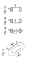
- the gas bag 30 is shown separately again in FIG.
- FIGS. 4a to 4c show different positions of the central region 36 relative to the inflated chamber 34.
- the middle area is consisting of a sewn-in central part of the airbag fabric in section positioned centrally to chamber 34.
- the central region 36 is on the Occupant-facing side of the chamber 34 is arranged.
- the central area 36 is on that of the door or Side wall associated side of the chamber 34 located.
- central region 36 is not necessarily a non-inflatable one Area must be.
- the central region 36 could also, as in FIG. 4a dashed lines, an inflatable area that is in the Cross-section and horizontally across the vehicle's longitudinal direction, however, one clearly has a smaller thickness d than the chamber 34 in order to force the case to achieve a lateral intrusion over the pelvis and shoulder.
Landscapes
- Engineering & Computer Science (AREA)
- Mechanical Engineering (AREA)
- Aviation & Aerospace Engineering (AREA)
- Transportation (AREA)
- Air Bags (AREA)
Abstract
Description
- Figur 1 eine Seitenansicht des erfindungsgemäßen Fahrzeugsitzes mit integrierter erfindungsgemäßer Oberkörper-Seitenschutzeinrichtung samt eines Dummies,
- Figur 2 einen Schnitt durch den Fahrzeugsitz samt Schutzeinrichtung und den Dummy längs der Linie II-II nach Figur 1,
- Figur 3 eine Seitenansicht nur des Seitengassacks, der in Figur 1 dargestellt ist, im aufgeblasenen Zustand, und
- Figuren 4a bis 4c Schnittansichten durch,den Gassack nach Figur 3 längs der Linie IV-IV in drei verschiedenen Modifikationen.
Claims (8)
- Oberkörper-Seitenschutzeinrichtung für einen Insassen eines einen Fahrzeugsitz aufweisenden Fahrzeugs, wobei der Sitz eine Sitzfläche (12) und eine Rückenlehne (14) aufweist, mit einem sich seitlich des Oberkörpers erstreckenden Seitengassacks (30), der eine ringförmige, aufblasbare Kammer (34) aufweist, welche sich von der Sitzfläche (12) seitlich des Oberkörpers bis wenigstens nahe des oberen Randes (50) der Rückenlehne (14) erstreckt und einen mittleren Bereich (36) des Gassacks (30) umgibt, welcher im aufgeblasenen Zustand des Gassacks (30) eine geringere Dicke (d), horizontal und quer zur Fahrzeuglängsrichtung (A) gemessen, hat als die Kammer (34).
- Oberkörper-Seitenschutzeinrichtung nach Anspruch 1, dadurch gekennzeichnet, daß der mittlere Bereich (36) nicht aufblasbar ausgeführt ist.
- Oberkörper-Seitenschutzeinrichtung nach Anspruch 1 oder 2, dadurch gekennzeichnet, daß die aufblasbare Kammer (34) umfangsmäßig ringförmig geschlossen ist.
- Oberkörper-Seitenschutzeinrichtung nach einem der vorhergehenden Ansprüche, dadurch gekennzeichnet, daß die aufblasbare Kammer (34) im aufgeblasenen Zustand oval ist und ihre Haupterstreckungsrichtung H im wesentlichen parallel zur Rückenlehne (14) verläuft.
- Oberkörper-Seitenschutzeinrichtung nach einem der vorhergehenden Ansprüche, dadurch gekennzeichnet, daß in Seitenansicht der eingebaute, aufgeblasene Seitengassack (30) einen oberen und einen unteren Abschnitt (40, 42) hat, die breiter als seitliche Abschnitte (44, 46) sind, welche den oberen Abschnitt (40) mit dem unteren Abschnitt (42) verbinden.
- Oberkörper-Seitenschutzeinrichtung nach einem der vorhergehenden Ansprüche, dadurch gekennzeichnet, daß der aufgeblasene Seitengassack (30), in Seitenansicht und in eingebautem, aufgeblasenem Zustand, längs einer Breite von maximal etwa 300 mm parallel zur Rückenlehne von der Sitzfläche (12) aufwärts der Rückenlehne (14) verläuft.
- Oberkörper-Seitenschutzeinrichtung nach einem der vorhergehenden Ansprüche, dadurch gekennzeichnet, daß der mittlere Bereich (36) oberhalb von etwa 200 mm über der Sitzfläche (12), bezogen auf den aufgeblasenen Zustand des Seitengassacks (30), beginnt und sich maximal bis ca. 150 mm unterhalb des oberen Randes (50) der Rückenlehne (14) erstreckt.
- Fahrzeugsitz, dadurch gekennzeichnet, daß er eine in der Rückenlehne (14) integrierte Oberkörper-Seitenschutzeinrichtung nach einem der vorstehenden Ansprüche aufweist.
Applications Claiming Priority (2)
| Application Number | Priority Date | Filing Date | Title |
|---|---|---|---|
| DE10231631 | 2002-07-12 | ||
| DE10231631A DE10231631A1 (de) | 2002-07-12 | 2002-07-12 | Oberkörper-Seitenschutzeinrichtung für einen Fahrzeuginsassen und Fahrzeugsitz |
Publications (2)
| Publication Number | Publication Date |
|---|---|
| EP1380475A1 true EP1380475A1 (de) | 2004-01-14 |
| EP1380475B1 EP1380475B1 (de) | 2006-03-08 |
Family
ID=29723879
Family Applications (1)
| Application Number | Title | Priority Date | Filing Date |
|---|---|---|---|
| EP03015510A Expired - Lifetime EP1380475B1 (de) | 2002-07-12 | 2003-07-09 | Oberkörper-Seitenschutzeinrichtung für einen Fahrzeuginsassen und Fahrzeugsitz |
Country Status (4)
| Country | Link |
|---|---|
| US (1) | US7080880B2 (de) |
| EP (1) | EP1380475B1 (de) |
| DE (2) | DE10231631A1 (de) |
| ES (1) | ES2260551T3 (de) |
Cited By (4)
| Publication number | Priority date | Publication date | Assignee | Title |
|---|---|---|---|---|
| EP1864870A3 (de) * | 2006-06-09 | 2009-05-06 | GM Global Technology Operations, Inc. | Seitenairbagmodul und Sicherheitseinrichtung für ein Kraftfahrzeug mit einem solchen Seitenairbagmodul |
| US8246076B2 (en) | 2008-12-18 | 2012-08-21 | Takata AG | Airbag for a vehicle occupant restraint system and a method for protecting a vehicle occupant |
| US8632094B2 (en) | 2008-12-17 | 2014-01-21 | Takata AG | Airbag for a vehicle occupant restraining system |
| EP2796315A4 (de) * | 2011-12-20 | 2015-03-11 | Toyota Motor Co Ltd | Fahrzeugsitz |
Families Citing this family (2)
| Publication number | Priority date | Publication date | Assignee | Title |
|---|---|---|---|---|
| DE102004017650B4 (de) * | 2004-04-05 | 2010-07-22 | Takata-Petri Ag | Sicherheitsanordnung für Kraftfahrzeuge |
| DE102018114771B4 (de) * | 2018-06-20 | 2020-07-09 | Isi Automotive Holding Gmbh | Rückhaltevorrichtung zur Reduzierung einer schlagartigen Seitwärts- als auch Vorwärtsbewegung eines Insassen |
Citations (5)
| Publication number | Priority date | Publication date | Assignee | Title |
|---|---|---|---|---|
| US3731949A (en) * | 1971-05-12 | 1973-05-08 | Allied Chem | Flat bag made of tubular sections |
| DE3833889A1 (de) * | 1988-10-05 | 1990-04-12 | Bayerische Motoren Werke Ag | Aufprallschutzvorrichtung fuer kraftfahrzeuginsassen |
| US5439247A (en) * | 1992-09-29 | 1995-08-08 | Trw Repa Gmbh | Inflatable gas bag for a vehicular restraining system |
| US5722685A (en) * | 1995-11-02 | 1998-03-03 | Trw Occupant Restraint Systems Gmbh | Gas bag lateral impact protective device |
| DE19930157A1 (de) * | 1999-06-30 | 2001-01-04 | Takata Europ Gmbh | Luftsack für ein Kraftfahrzeug |
Family Cites Families (10)
| Publication number | Priority date | Publication date | Assignee | Title |
|---|---|---|---|---|
| US5556128A (en) * | 1994-11-24 | 1996-09-17 | Volkswagen Ag | Safety arrangement for a vehicle occupant |
| US5615909A (en) * | 1995-12-27 | 1997-04-01 | Trw Vehicle Safety Systems Inc. | Vehicle safety apparatus |
| US5913536A (en) | 1996-02-07 | 1999-06-22 | Trw Vehicle Safety System Inc. | Air bag module |
| DE19605620B4 (de) * | 1996-02-15 | 2004-07-22 | Siemens Restraint Systems Gmbh | Den Thoraxbereich entlastendes Seitenairbagmodul und Gassack hierfür |
| JP2962225B2 (ja) * | 1996-04-08 | 1999-10-12 | 三菱自動車工業株式会社 | 側面衝突用エアバッグ |
| US6302431B1 (en) * | 1997-09-19 | 2001-10-16 | Nissan Motor Co., Ltd. | Air bag device |
| JP4014068B2 (ja) * | 1999-07-28 | 2007-11-28 | 芦森工業株式会社 | エアバッグ装置 |
| US6742805B2 (en) * | 2001-05-02 | 2004-06-01 | Trw Vehicle Safety Systems Inc. | Multi-layered inflatable curtain |
| US20040124615A1 (en) * | 2001-06-08 | 2004-07-01 | Toshinori Tanase | Side air bag device |
| EP1393997A4 (de) | 2001-06-08 | 2008-03-26 | Toyoda Gosei Kk | Seitenairbagvorrichtung |
-
2002
- 2002-07-12 DE DE10231631A patent/DE10231631A1/de not_active Withdrawn
-
2003
- 2003-07-09 US US10/616,345 patent/US7080880B2/en not_active Expired - Lifetime
- 2003-07-09 EP EP03015510A patent/EP1380475B1/de not_active Expired - Lifetime
- 2003-07-09 DE DE50302570T patent/DE50302570D1/de not_active Expired - Fee Related
- 2003-07-09 ES ES03015510T patent/ES2260551T3/es not_active Expired - Lifetime
Patent Citations (5)
| Publication number | Priority date | Publication date | Assignee | Title |
|---|---|---|---|---|
| US3731949A (en) * | 1971-05-12 | 1973-05-08 | Allied Chem | Flat bag made of tubular sections |
| DE3833889A1 (de) * | 1988-10-05 | 1990-04-12 | Bayerische Motoren Werke Ag | Aufprallschutzvorrichtung fuer kraftfahrzeuginsassen |
| US5439247A (en) * | 1992-09-29 | 1995-08-08 | Trw Repa Gmbh | Inflatable gas bag for a vehicular restraining system |
| US5722685A (en) * | 1995-11-02 | 1998-03-03 | Trw Occupant Restraint Systems Gmbh | Gas bag lateral impact protective device |
| DE19930157A1 (de) * | 1999-06-30 | 2001-01-04 | Takata Europ Gmbh | Luftsack für ein Kraftfahrzeug |
Cited By (5)
| Publication number | Priority date | Publication date | Assignee | Title |
|---|---|---|---|---|
| EP1864870A3 (de) * | 2006-06-09 | 2009-05-06 | GM Global Technology Operations, Inc. | Seitenairbagmodul und Sicherheitseinrichtung für ein Kraftfahrzeug mit einem solchen Seitenairbagmodul |
| US8632094B2 (en) | 2008-12-17 | 2014-01-21 | Takata AG | Airbag for a vehicle occupant restraining system |
| US8246076B2 (en) | 2008-12-18 | 2012-08-21 | Takata AG | Airbag for a vehicle occupant restraint system and a method for protecting a vehicle occupant |
| EP2796315A4 (de) * | 2011-12-20 | 2015-03-11 | Toyota Motor Co Ltd | Fahrzeugsitz |
| US9376040B2 (en) | 2011-12-20 | 2016-06-28 | Toyota Jidosha Kabushiki Kaisha | Vehicular seat |
Also Published As
| Publication number | Publication date |
|---|---|
| US7080880B2 (en) | 2006-07-25 |
| EP1380475B1 (de) | 2006-03-08 |
| DE10231631A1 (de) | 2004-07-15 |
| ES2260551T3 (es) | 2006-11-01 |
| DE50302570D1 (de) | 2006-05-04 |
| US20040007905A1 (en) | 2004-01-15 |
Similar Documents
| Publication | Publication Date | Title |
|---|---|---|
| EP0771698B1 (de) | Gassack-Seitenaufprall-Schutzeinrichtung | |
| WO2020156953A1 (de) | Gassackanordnung für ein fahrzeuginsassen-rückhaltesystem | |
| DE19628259C2 (de) | Seitenairbagmodul | |
| DE112017000853B4 (de) | Zur Mitte weisendes Seitenairbagmodul | |
| EP0952043B1 (de) | Knieschutzeinrichtung für Fahrzeuginsassen | |
| DE102010036315B4 (de) | Airbag-Baugruppe | |
| DE19824601C2 (de) | Luftsack mit Ausgleichsvolumen | |
| DE10147965B4 (de) | Aufblasbarer Seitenvorhang | |
| DE102007045504B4 (de) | Fahrzeugseitenairbagvorrichtung | |
| DE112015005589T5 (de) | Airbag-modul | |
| EP1048531A2 (de) | Seitenaufprall-Schutzeinrichtung für Fahrzeuginsassen | |
| DE102005028702A1 (de) | Airbag-Vorrichtung | |
| DE19847854A1 (de) | Zweikammerluftsack | |
| DE29610920U1 (de) | Airbagvorrichtung | |
| DE102018129852A1 (de) | Verschachteltes Überkopf-Airbagsystem | |
| EP2424750A2 (de) | Gassackmodul zum schutz des thorax- und kopfbereichs eines fahrzeuginsassen | |
| DE102014008599A1 (de) | Seitenairbagvorrichtung | |
| WO2019193082A1 (de) | Fahrzeuginsassen-rückhaltesystem mit einem seitengassack | |
| EP1917165B1 (de) | Fahrer- oder beifahrerairbagmodul mit einem gassack | |
| DE102008058855A1 (de) | Insassen-Airbag-Struktur für ein Fahrzeug | |
| DE10122838B4 (de) | Luftsack für ein Curtain-Airbag Modul | |
| DE102008007235A1 (de) | Seitenairbagvorrichtung | |
| DE602004008426T2 (de) | Airbagfaltverfahren | |
| EP1567394A1 (de) | Gassack für eine insassenschutzeinrichtung | |
| EP4077061B1 (de) | Luftsack für eine airbaganordnung und airbaganorndung eines fahrzeugsitzes |
Legal Events
| Date | Code | Title | Description |
|---|---|---|---|
| PUAI | Public reference made under article 153(3) epc to a published international application that has entered the european phase |
Free format text: ORIGINAL CODE: 0009012 |
|
| AK | Designated contracting states |
Kind code of ref document: A1 Designated state(s): AT BE BG CH CY CZ DE DK EE ES FI FR GB GR HU IE IT LI LU MC NL PT RO SE SI SK TR |
|
| AX | Request for extension of the european patent |
Extension state: AL LT LV MK |
|
| 17P | Request for examination filed |
Effective date: 20040621 |
|
| AKX | Designation fees paid |
Designated state(s): DE ES FR IT |
|
| 17Q | First examination report despatched |
Effective date: 20050124 |
|
| GRAP | Despatch of communication of intention to grant a patent |
Free format text: ORIGINAL CODE: EPIDOSNIGR1 |
|
| GRAS | Grant fee paid |
Free format text: ORIGINAL CODE: EPIDOSNIGR3 |
|
| GRAA | (expected) grant |
Free format text: ORIGINAL CODE: 0009210 |
|
| RAP1 | Party data changed (applicant data changed or rights of an application transferred) |
Owner name: TRW AUTOMOTIVE GMBH |
|
| AK | Designated contracting states |
Kind code of ref document: B1 Designated state(s): DE ES FR IT |
|
| REF | Corresponds to: |
Ref document number: 50302570 Country of ref document: DE Date of ref document: 20060504 Kind code of ref document: P |
|
| PGFP | Annual fee paid to national office [announced via postgrant information from national office to epo] |
Ref country code: FR Payment date: 20060705 Year of fee payment: 4 |
|
| PGFP | Annual fee paid to national office [announced via postgrant information from national office to epo] |
Ref country code: ES Payment date: 20060717 Year of fee payment: 4 |
|
| PGFP | Annual fee paid to national office [announced via postgrant information from national office to epo] |
Ref country code: IT Payment date: 20060731 Year of fee payment: 4 Ref country code: DE Payment date: 20060731 Year of fee payment: 4 |
|
| ET | Fr: translation filed | ||
| REG | Reference to a national code |
Ref country code: ES Ref legal event code: FG2A Ref document number: 2260551 Country of ref document: ES Kind code of ref document: T3 |
|
| PLBE | No opposition filed within time limit |
Free format text: ORIGINAL CODE: 0009261 |
|
| STAA | Information on the status of an ep patent application or granted ep patent |
Free format text: STATUS: NO OPPOSITION FILED WITHIN TIME LIMIT |
|
| 26N | No opposition filed |
Effective date: 20061211 |
|
| PG25 | Lapsed in a contracting state [announced via postgrant information from national office to epo] |
Ref country code: DE Free format text: LAPSE BECAUSE OF NON-PAYMENT OF DUE FEES Effective date: 20080201 |
|
| REG | Reference to a national code |
Ref country code: FR Ref legal event code: ST Effective date: 20080331 |
|
| PG25 | Lapsed in a contracting state [announced via postgrant information from national office to epo] |
Ref country code: FR Free format text: LAPSE BECAUSE OF NON-PAYMENT OF DUE FEES Effective date: 20070731 |
|
| REG | Reference to a national code |
Ref country code: ES Ref legal event code: FD2A Effective date: 20070710 |
|
| PG25 | Lapsed in a contracting state [announced via postgrant information from national office to epo] |
Ref country code: ES Free format text: LAPSE BECAUSE OF NON-PAYMENT OF DUE FEES Effective date: 20070710 |
|
| PG25 | Lapsed in a contracting state [announced via postgrant information from national office to epo] |
Ref country code: IT Free format text: LAPSE BECAUSE OF NON-PAYMENT OF DUE FEES Effective date: 20070709 |