EP1380459A1 - Fixing method of in-wheel motor and in-wheel motor system - Google Patents
Fixing method of in-wheel motor and in-wheel motor system Download PDFInfo
- Publication number
- EP1380459A1 EP1380459A1 EP02717154A EP02717154A EP1380459A1 EP 1380459 A1 EP1380459 A1 EP 1380459A1 EP 02717154 A EP02717154 A EP 02717154A EP 02717154 A EP02717154 A EP 02717154A EP 1380459 A1 EP1380459 A1 EP 1380459A1
- Authority
- EP
- European Patent Office
- Prior art keywords
- motor
- wheel
- inwheel
- rotary case
- direct
- Prior art date
- Legal status (The legal status is an assumption and is not a legal conclusion. Google has not performed a legal analysis and makes no representation as to the accuracy of the status listed.)
- Granted
Links
Images
























Classifications
-
- B—PERFORMING OPERATIONS; TRANSPORTING
- B60—VEHICLES IN GENERAL
- B60K—ARRANGEMENT OR MOUNTING OF PROPULSION UNITS OR OF TRANSMISSIONS IN VEHICLES; ARRANGEMENT OR MOUNTING OF PLURAL DIVERSE PRIME-MOVERS IN VEHICLES; AUXILIARY DRIVES FOR VEHICLES; INSTRUMENTATION OR DASHBOARDS FOR VEHICLES; ARRANGEMENTS IN CONNECTION WITH COOLING, AIR INTAKE, GAS EXHAUST OR FUEL SUPPLY OF PROPULSION UNITS IN VEHICLES
- B60K7/00—Disposition of motor in, or adjacent to, traction wheel
- B60K7/0007—Disposition of motor in, or adjacent to, traction wheel the motor being electric
-
- B—PERFORMING OPERATIONS; TRANSPORTING
- B60—VEHICLES IN GENERAL
- B60G—VEHICLE SUSPENSION ARRANGEMENTS
- B60G3/00—Resilient suspensions for a single wheel
- B60G3/18—Resilient suspensions for a single wheel with two or more pivoted arms, e.g. parallelogram
- B60G3/20—Resilient suspensions for a single wheel with two or more pivoted arms, e.g. parallelogram all arms being rigid
-
- B—PERFORMING OPERATIONS; TRANSPORTING
- B60—VEHICLES IN GENERAL
- B60G—VEHICLE SUSPENSION ARRANGEMENTS
- B60G7/00—Pivoted suspension arms; Accessories thereof
- B60G7/008—Attaching arms to unsprung part of vehicle
-
- B—PERFORMING OPERATIONS; TRANSPORTING
- B60—VEHICLES IN GENERAL
- B60K—ARRANGEMENT OR MOUNTING OF PROPULSION UNITS OR OF TRANSMISSIONS IN VEHICLES; ARRANGEMENT OR MOUNTING OF PLURAL DIVERSE PRIME-MOVERS IN VEHICLES; AUXILIARY DRIVES FOR VEHICLES; INSTRUMENTATION OR DASHBOARDS FOR VEHICLES; ARRANGEMENTS IN CONNECTION WITH COOLING, AIR INTAKE, GAS EXHAUST OR FUEL SUPPLY OF PROPULSION UNITS IN VEHICLES
- B60K17/00—Arrangement or mounting of transmissions in vehicles
- B60K17/32—Arrangement or mounting of transmissions in vehicles the ultimate propulsive elements, e.g. ground wheels, being rockable about a horizontal pivot
-
- F—MECHANICAL ENGINEERING; LIGHTING; HEATING; WEAPONS; BLASTING
- F16—ENGINEERING ELEMENTS AND UNITS; GENERAL MEASURES FOR PRODUCING AND MAINTAINING EFFECTIVE FUNCTIONING OF MACHINES OR INSTALLATIONS; THERMAL INSULATION IN GENERAL
- F16F—SPRINGS; SHOCK-ABSORBERS; MEANS FOR DAMPING VIBRATION
- F16F15/00—Suppression of vibrations in systems; Means or arrangements for avoiding or reducing out-of-balance forces, e.g. due to motion
- F16F15/02—Suppression of vibrations of non-rotating, e.g. reciprocating systems; Suppression of vibrations of rotating systems by use of members not moving with the rotating systems
- F16F15/04—Suppression of vibrations of non-rotating, e.g. reciprocating systems; Suppression of vibrations of rotating systems by use of members not moving with the rotating systems using elastic means
-
- F—MECHANICAL ENGINEERING; LIGHTING; HEATING; WEAPONS; BLASTING
- F16—ENGINEERING ELEMENTS AND UNITS; GENERAL MEASURES FOR PRODUCING AND MAINTAINING EFFECTIVE FUNCTIONING OF MACHINES OR INSTALLATIONS; THERMAL INSULATION IN GENERAL
- F16F—SPRINGS; SHOCK-ABSORBERS; MEANS FOR DAMPING VIBRATION
- F16F15/00—Suppression of vibrations in systems; Means or arrangements for avoiding or reducing out-of-balance forces, e.g. due to motion
- F16F15/10—Suppression of vibrations in rotating systems by making use of members moving with the system
- F16F15/18—Suppression of vibrations in rotating systems by making use of members moving with the system using electric, magnetic or electromagnetic means
-
- B—PERFORMING OPERATIONS; TRANSPORTING
- B60—VEHICLES IN GENERAL
- B60G—VEHICLE SUSPENSION ARRANGEMENTS
- B60G2200/00—Indexing codes relating to suspension types
- B60G2200/10—Independent suspensions
- B60G2200/14—Independent suspensions with lateral arms
- B60G2200/144—Independent suspensions with lateral arms with two lateral arms forming a parallelogram
-
- B—PERFORMING OPERATIONS; TRANSPORTING
- B60—VEHICLES IN GENERAL
- B60G—VEHICLE SUSPENSION ARRANGEMENTS
- B60G2200/00—Indexing codes relating to suspension types
- B60G2200/40—Indexing codes relating to the wheels in the suspensions
- B60G2200/422—Driving wheels or live axles
-
- B—PERFORMING OPERATIONS; TRANSPORTING
- B60—VEHICLES IN GENERAL
- B60G—VEHICLE SUSPENSION ARRANGEMENTS
- B60G2200/00—Indexing codes relating to suspension types
- B60G2200/40—Indexing codes relating to the wheels in the suspensions
- B60G2200/44—Indexing codes relating to the wheels in the suspensions steerable
-
- B—PERFORMING OPERATIONS; TRANSPORTING
- B60—VEHICLES IN GENERAL
- B60G—VEHICLE SUSPENSION ARRANGEMENTS
- B60G2202/00—Indexing codes relating to the type of spring, damper or actuator
- B60G2202/30—Spring/Damper and/or actuator Units
- B60G2202/31—Spring/Damper and/or actuator Units with the spring arranged around the damper, e.g. MacPherson strut
- B60G2202/312—The spring being a wound spring
-
- B—PERFORMING OPERATIONS; TRANSPORTING
- B60—VEHICLES IN GENERAL
- B60G—VEHICLE SUSPENSION ARRANGEMENTS
- B60G2204/00—Indexing codes related to suspensions per se or to auxiliary parts
- B60G2204/10—Mounting of suspension elements
- B60G2204/14—Mounting of suspension arms
- B60G2204/148—Mounting of suspension arms on the unsprung part of the vehicle, e.g. wheel knuckle or rigid axle
-
- B—PERFORMING OPERATIONS; TRANSPORTING
- B60—VEHICLES IN GENERAL
- B60G—VEHICLE SUSPENSION ARRANGEMENTS
- B60G2204/00—Indexing codes related to suspensions per se or to auxiliary parts
- B60G2204/10—Mounting of suspension elements
- B60G2204/30—In-wheel mountings
-
- B—PERFORMING OPERATIONS; TRANSPORTING
- B60—VEHICLES IN GENERAL
- B60G—VEHICLE SUSPENSION ARRANGEMENTS
- B60G2204/00—Indexing codes related to suspensions per se or to auxiliary parts
- B60G2204/40—Auxiliary suspension parts; Adjustment of suspensions
- B60G2204/418—Bearings, e.g. ball or roller bearings
-
- B—PERFORMING OPERATIONS; TRANSPORTING
- B60—VEHICLES IN GENERAL
- B60G—VEHICLE SUSPENSION ARRANGEMENTS
- B60G2300/00—Indexing codes relating to the type of vehicle
- B60G2300/50—Electric vehicles; Hybrid vehicles
-
- B—PERFORMING OPERATIONS; TRANSPORTING
- B60—VEHICLES IN GENERAL
- B60G—VEHICLE SUSPENSION ARRANGEMENTS
- B60G2300/00—Indexing codes relating to the type of vehicle
- B60G2300/60—Vehicles using regenerative power
-
- B—PERFORMING OPERATIONS; TRANSPORTING
- B60—VEHICLES IN GENERAL
- B60K—ARRANGEMENT OR MOUNTING OF PROPULSION UNITS OR OF TRANSMISSIONS IN VEHICLES; ARRANGEMENT OR MOUNTING OF PLURAL DIVERSE PRIME-MOVERS IN VEHICLES; AUXILIARY DRIVES FOR VEHICLES; INSTRUMENTATION OR DASHBOARDS FOR VEHICLES; ARRANGEMENTS IN CONNECTION WITH COOLING, AIR INTAKE, GAS EXHAUST OR FUEL SUPPLY OF PROPULSION UNITS IN VEHICLES
- B60K17/00—Arrangement or mounting of transmissions in vehicles
- B60K17/04—Arrangement or mounting of transmissions in vehicles characterised by arrangement, location or kind of gearing
- B60K17/043—Transmission unit disposed in on near the vehicle wheel, or between the differential gear unit and the wheel
- B60K17/046—Transmission unit disposed in on near the vehicle wheel, or between the differential gear unit and the wheel with planetary gearing having orbital motion
-
- B—PERFORMING OPERATIONS; TRANSPORTING
- B60—VEHICLES IN GENERAL
- B60K—ARRANGEMENT OR MOUNTING OF PROPULSION UNITS OR OF TRANSMISSIONS IN VEHICLES; ARRANGEMENT OR MOUNTING OF PLURAL DIVERSE PRIME-MOVERS IN VEHICLES; AUXILIARY DRIVES FOR VEHICLES; INSTRUMENTATION OR DASHBOARDS FOR VEHICLES; ARRANGEMENTS IN CONNECTION WITH COOLING, AIR INTAKE, GAS EXHAUST OR FUEL SUPPLY OF PROPULSION UNITS IN VEHICLES
- B60K7/00—Disposition of motor in, or adjacent to, traction wheel
- B60K2007/0038—Disposition of motor in, or adjacent to, traction wheel the motor moving together with the wheel axle
-
- B—PERFORMING OPERATIONS; TRANSPORTING
- B60—VEHICLES IN GENERAL
- B60K—ARRANGEMENT OR MOUNTING OF PROPULSION UNITS OR OF TRANSMISSIONS IN VEHICLES; ARRANGEMENT OR MOUNTING OF PLURAL DIVERSE PRIME-MOVERS IN VEHICLES; AUXILIARY DRIVES FOR VEHICLES; INSTRUMENTATION OR DASHBOARDS FOR VEHICLES; ARRANGEMENTS IN CONNECTION WITH COOLING, AIR INTAKE, GAS EXHAUST OR FUEL SUPPLY OF PROPULSION UNITS IN VEHICLES
- B60K7/00—Disposition of motor in, or adjacent to, traction wheel
- B60K2007/0092—Disposition of motor in, or adjacent to, traction wheel the motor axle being coaxial to the wheel axle
Definitions
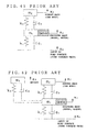
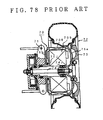
- Fig. 78 shows that a direct drive motor of a hollow outer rotor type (inwheel motor) 70 disclosed by JP 2676025 is mounted.
- a stator 70S is connected to and supported by an upright 71 which is a fixed portion, located on the inner side of the wheel disk 73 of a direct drive wheel 72, and also connected to a rotary shaft 74 coupled to the above wheel disk 73 through a bearing 74J.
- a rotor 70R around the above stator 70S is supported by a first bracket 75a connected to the above rotary shaft 74 and a second bracket 75b which is rotatably fixed to the upright 71 through a bearing 71J. Since the rotor 70R is thereby rotatably connected to the stator 70S, torque can be transmitted to the wheel 72 by driving the inwheel motor 70 so that the wheel 72 can be directly driven.
- stator 90S of an inwheel motor 90 is fixed to a steering knuckle 93 connected to a hub portion 92 through a bearing 91 and in which the rim portion 94a of a wheel 94 is used as the rotor of the motor to be rotatably linked to the stator 90S (for example, Japanese Laid-open Patent Application No. 10-305735).
- the motor stator of the inwheel motor is rotatably fixed to a spindle shaft connected to a part called “upright” or “knuckle” which is one of parts around the wheels of the vehicle, the unsprung mass increases when the above inwheel motor is mounted, thereby deteriorating the road holding properties.
- a method of mounting an inwheel motor to a direct drive wheel comprising mounting the motor to an unsprung mass corresponding portion of a vehicle by a buffer member or a buffer unit.
- a method of mounting an inwheel motor wherein the non-rotary case of the motor for supporting the stator of the motor and a knuckle which is a part around the wheel of the vehicle are interconnected by a direct-acting guide unit, and the rotary case of the motor for supporting the rotor of the motor and the wheel are interconnected by a driving force transmission unit which can be eccentric from the wheel in the radial direction.
- a method of mounting an inwheel motor wherein the non-rotary case of the motor and a knuckle are interconnected by a direct-acting guide unit including a damper, and the rotary case of the motor and the wheel are interconnected by a second elastic member.
- a method of mounting an inwheel motor to a direct drive wheel comprising mounting the non-rotary case of the motor on a car body side by a buffer unit.
- an inwheel motor system comprising a hollow electric motor in a wheel portion to drive the wheel, wherein the motor is mounted to an unsprung mass corresponding portion of a wheel, a car body side, or both of them, by a buffer member or a buffer unit.
- an inwheel motor system wherein the motor and the wheel are interconnected by a constant-velocity universal joint or by a driving force transmission unit which can be eccentric from the wheel in the radial direction.
- an inwheel motor system wherein the driving force transmission unit is a coupling unit which comprises a plurality of hollow disk-like plates and direct-acting guides for interconnecting adjacent plates and for guiding the adjacent plates in the radial direction of the disk.
- an inwheel motor system wherein the non-rotary case of the motor for supporting the stator of the motor and a knuckle which is a part around the wheel of a vehicle are interconnected by a direct-acting guide unit.
- an inwheel motor system wherein a buffer member or a buffer unit is provided between the non-rotary case of the motor and the knuckle or/and between the rotary case and the wheel.
- an inwheel motor system wherein the non-rotary case of the motor for supporting the stator of the motor and a knuckle which is a part around the wheel of the vehicle are interconnected by a first elastic member, and the rotary case of the motor for supporting a rotor and the wheel are interconnected by a second elastic member.
- an inwheel motor system wherein the wheel and the rotary case are interconnected by 16 or less board-like elastic members disposed at equal intervals in parallel to the tangent direction of the wheel.
- an inwheel motor system wherein rotary joint units whose axes are in the tangent direction of the motor are provided on both end faces in the width direction of the plate-like elastic members.
- an inwheel motor system wherein ribs extending from the rotary case toward the wheel and ribs extending from the wheel toward the rotary case are interconnected by an elastic member at a plurality of sites.
- an inwheel motor system wherein the vertical elastic coefficient of a material constituting the first and second elastic members is 10 to 300 GPa.
- an inwheel motor system wherein the first elastic member has a lower elastic modulus in the vertical direction of the vehicle than an elastic modulus in the longitudinal direction.
- an inwheel motor system wherein the non-rotary case is connected to the knuckle by a direct-acting guide unit having a spring and a damper in place of the first elastic member.
- an inwheel motor system wherein the rotary case is connected to the wheel by a constant-velocity universal joint.
- an inwheel motor system wherein the rotary case is connected to the wheel by a coupling unit comprising a plurality of hollow disk-like plates and direct-acting guides for interconnecting adjacent plates and for guiding the adjacent plates in the radial direction of the disk.
- an inwheel motor system wherein the non-rotary case of the motor for supporting the stator of the motor is connected to the knuckle which is a part around the wheel of the vehicle by a buffer member or buffer unit, and the rotary case of the motor is connected to the wheel by a coupling unit comprising a plurality of hollow disk-like plates and direct-acting guides for interconnecting adjacent plates and for guiding the adjacent plates in the radial direction of the disk.
- an inwheel motor system wherein the non-rotary case of the motor for supporting the stator of the motor is connected to the knuckle which is a part around the wheel of the vehicle by a buffer member or buffer unit, and the rotary case of the motor is connected to the wheel by a hollow disk-like plate having a plurality of direct-acting guides on the motor side and the wheel side.
- an inwheel motor system wherein the direct-acting guides are disposed at the same positions on the front and back sides of the hollow disk-like plate at an interval of 90° or 180° in the circumferential direction of the plate.
- an inwheel motor system wherein the working directions of all the direct-acting guides on the motor side are 45° from the radial direction of the hollow disk-like plate, and the working directions of all the direct-acting guides on the wheel side are perpendicular to the working directions of all the direct-acting guides on the motor side.
- an inwheel motor system wherein the non-rotary case of the motor for supporting the stator of the motor is connected to the knuckle which is a part around the wheel of the motor by a buffer member or a buffer unit, and the rotary case of the motor is connected to the wheel by a first hollow disk-like plate comprising a plurality of direct-acting guides on the motor side and the wheel side and by a second hollow disk-like plate disposed on the inner side of the first hollow disk-like plate and comprising a plurality of direct-acting guides arranged in an opposite way to that of the first hollow disk-like plate.
- an inwheel motor system wherein the mass of the first hollow disk-like plate is made equal to the mass of the second hollow disk-like plate.
- each of the direct-acting guides consists of a guide rail having at least one recess or projection extending in the radial direction of the plate and of a guide member to be engaged with the guide rail.
- an inwheel motor system wherein steel balls are placed between the guide rail and the guide member.
- an inwheel motor system wherein the non-rotary case of the motor for supporting the stator of the motor and a knuckle which is a part around the wheel of the vehicle are interconnected by a buffer member comprising at least one pair of substantially A-shaped or H-shaped link units, each having two arms rotatably interconnected by a spring and a damper, the end of one arm being connected to the non-rotary case and the end of the other arm being connected to the knuckle.
- an inwheel motor system wherein the motor is supported to a knuckle which is a part around the wheel by direct-acting guides and a buffer unit in such a manner that it can move in the vertical direction of the vehicle, and the buffer unit has valves between a hydraulic cylinder and a reservoir tank.
- an inwheel motor system wherein the piston upper chamber and piston lower chamber of the hydraulic cylinder are each provided with a working oil passage having an independent valve, and the two working oil passages are connected to a common reservoir tank.
- an inwheel motor system wherein the piston upper chamber and piston lower chamber of the hydraulic cylinder are interconnected by working oil passages, each having an independent valve, and the piston lower chamber is connected to a reservoir tank.
- an inwheel motor system wherein a brake disk or brake drum is mounted to the hub portion.
- an inwheel motor system having a hollow electric motor in a wheel portion to drive a wheel, wherein the motor is supported to a knuckle which is a part around the wheel of a vehicle by direct-acting guides and buffer members in the vertical direction of the vehicle and by direct-acting guides and buffer members in the longitudinal direction of the vehicle, and the rotary case of the motor and the wheel are interconnected by a flexible coupling or constant-velocity universal joint in such a manner that they can be eccentric from each other.
- an inwheel motor system wherein the motor is an outer rotor type motor.
- an inwheel motor system having an electric motor in a wheel portion to drive a wheel, wherein the motor is a geared motor comprising a hollow inner rotor type motor and a speed reducing gear, the non-rotary case of this geared motor is supported to a knuckle which is a part around the wheel by direct-acting guides and buffer members in the vertical direction and by direct-acting guides and buffer members in the longitudinal direction of the vehicle, and the output shaft of the speed reducer and the wheel are interconnected by a shaft having a universal joint.
- the mass of the inwheel motor 3 is separated from an unsprung mass corresponding portion of the vehicle, such as the wheel 2 or the knuckle 5, and functions as the mass of a so-called dynamic damper. Therefore, the above dynamic damper serves to reduce a tire contact force fluctuation (to be abbreviated as TCFF hereinafter) when the vehicle runs over an uneven road, thereby improving the road holding properties of the vehicle. Even when the vehicle runs over a bad road, as vibration is not directly transmitted to the above inwheel motor 3, a load on the inwheel motor 3 imposed by vibration is reduced.
- TCFF tire contact force fluctuation
- the above motor 3 is mounted by suitably selecting the mass of the above motor 3 and the elastic constants of the first and second elastic members 11 and 13 which are buffer members to ensure that the resonance frequency of a motor section including the above mounted inwheel motor 3 should become higher than the resonance frequency of the sprung mass (car body) of the vehicle and lower than the resonance frequency of the unsprung mass including the wheel 2 and the knuckle 5, thereby making it possible to effectively reduce the level of TCFF when the vehicle runs over an uneven road.
- the spring constant in the radial direction of the above first elastic member 11 is set to a lower level in the vertical direction of the vehicle than that in the longitudinal direction, whereby the inwheel motor 3 can be moved only in substantially the vertical direction, thereby making it possible to suppress the co-rotation of the wheel 2 and the inwheel motor 3 and to improve the rotation drive efficiency of the wheel.
- elastic members 11a and 11b are provided only in the longitudinal direction as shown in Fig. 4, or an oval elastic member 11c having a long axis in the longitudinal direction is used as the first elastic members 11 as shown in Fig. 5.
- an oval elastic member 11c having a long axis in the longitudinal direction is used as the first elastic members 11 as shown in Fig. 5.
- first elastic member 11 and the second elastic member 13 are made from an elastic material such as rubber as in this embodiment, to obtain predetermined stiffness, a material having a vertical elastic coefficient of 1 to 120 MPa is preferably used as the material of the above first and second elastic members 11 and 13.
- the above elastic coefficient is more preferably 1 to 40 MPa.
- the vertical elastic coefficient of the material of the above first and second elastic members 11 and 13 is preferably set to 10 to 300 GPa.
- the non-rotary case 3a to which the stator 3S of the inwheel motor 3 is fixed is connected to the knuckle 5 which is a part around the wheel of the vehicle through the first elastic member 11 mounted to the connection member 12 extending from the knuckle 5, and the rotary case 3b to which the rotor 3R is fixed is connected to the wheel 2 through the second elastic member 13 so that the inwheel motor 3 serves as the weight of a dynamic damper for the unsprung mass, thereby making it possible to reduce the level of TCFF when the vehicle runs over an uneven road, to improve the road holding properties of the vehicle and to reduce a load on the inwheel motor 3 imposed by vibration.
- an inwheel motor car which has excellent space efficiency, excellent transmission efficiency of driving force and high road holding properties can be realized.
- the non-rotary case 3a of the inwheel motor 3 is mounted to the knuckle 5 through the first elastic member 11, and the rotary case 3b is mounted to the wheel 2 through the second elastic member 13.
- tire-like ring air springs 11T and 13T as shown in Fig. 6 are used in place of the above first and second elastic members 11 and 13, respectively, a spring constant in a shearing direction can be made high in spite of a low spring constant in the radial direction, thereby making it possible to constitute lightweight and highly elastic members.
- the non-rotary case 3a and the knuckle 5 may be connected by a direct-acting guide unit 14 which comprises a damper 14a and a support member 14b for supporting the damper 14a in the vertical direction of the vehicle in place of the above first elastic member 11 and the above connection member 12.
- a direct-acting guide unit 14 which comprises a damper 14a and a support member 14b for supporting the damper 14a in the vertical direction of the vehicle in place of the above first elastic member 11 and the above connection member 12.
- rotor-side ribs 2m extending from the rotary case 3b toward the wheel 2 and wheel-side ribs 2n extending from the wheel 2 toward the above rotary case 3b are interconnected by an elastic member 15 at equal intervals in the circumferential direction of the wheel 2 so that a shear spring having low stiffness in the vertical direction or a compression tension spring having high stiffness in the rotation direction can be used as a spring for interconnecting the wheel 2 and the inwheel motor 3. Therefore, the inwheel motor 3 can move only in substantially the vertical direction, and the co-rotation of the inwheel motor 3 and the wheel 2 can be further suppressed.
- the wheel 2 and the rotary case 3b are interconnected by a plurality of substantially board-like elastic members 13a to 13d arranged at equal intervals in parallel to the tangent direction of the wheel 2, whereby stiffness in the vertical direction can be made low and stiffness in the rotation direction can be made high.
- the number of the above board-like elastic members 13a to 13d is preferably 16 or less.
- stiffness in the vertical direction can also be reduced by providing the above rotary joint units likewise to connect one end of the above elastic member 13R to the wheel 2.
- a connection portion with a drive shaft 9 may be formed in the hub portion 4 connected to the wheel 2 at its rotation axis like a normal automobile to connect the hub portion 4 to the drive shaft 9.
- power from a car power engine or motor other than the inwheel motor 3 can be transmitted to the wheel 2 by the above drive shaft 9 so that a hybrid car can be constructed by connecting the output shaft of a gasoline engine vehicle to the hub portion 4 of the inwheel motor system of the present invention.
- the rotary case 3b and the wheel 2 are interconnected by the second elastic member 13.
- the above rotary case 3b may be connected to the wheel 2 by the second elastic member 13 and a constant-velocity universal joint 16.
- the non-rotary case 3a and the knuckle 5 are interconnected by the direct-acting guide unit 14 which comprises the damper 14a and the support member 14b shown in Fig. 7 and Fig. 8 of the above Embodiment 1 to further reduce the above phase difference.
- the above first elastic member 11 is preferably mounted at the center position of the mass of the motor in the width direction of the motor to prevent a part around the wheel from sharing the mass of the motor.
- the rotary case 3b and the wheel 2 are interconnected by the second elastic member 13 and the constant-velocity universal joint 16.
- a driving force transmitting unit which can be eccentric from the wheel 2 in the radial direction in place of the above constant-velocity universal joint 16
- torque transmission efficiency from the rotary case 3b to the wheel 2 can be further improved.
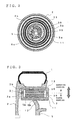
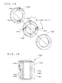
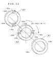
- a flexible coupling 18 which comprises a plurality of hollow disk-like plates 18A to 18C and direct-acting guides 18p and 18q for interconnecting the adjacent plates 18A and 18B and the adjacent plates 18B and 18C and for guiding the adjacent plates 18A and 18B and the adjacent plates 18B and 18C in the radial direction of the disk as shown in Figs. 16 to 18.
- the rotary case 3b is connected to the wheel 2 by the above flexible coupling 18 to minimize the phase difference between the wheel 2 and the rotary case 3b, thereby making it possible to further improve torque transmission efficiency from the rotary case 3b to the wheel 2.
- each of the above direct-acting guides 18p and 18q comprises a guide rail 18x having a projection extending in the radial direction of the above plate, a guide member 18y having a recess extending in the radial direction of the above plate and mating with the above guide rail 18x, and a plurality of steel balls 18m placed between the projection of the above guide rail 18x and the recess of the guide member 18y to slide the above guide rail 18x and the guide member 18y smoothly.
- the above guide rail 18x and guide member 18y are mounted on the opposing sides of the above adjacent plates 18A and 18B and the opposing sides of the above adjacent plates 18B and 18C, respectively.
- the inwheel motor 3 can move in the working direction of the above direct-acting guides 18p and 18q, that is, the radial direction of the disk but not in the rotation direction. As a result, rotating torque can be transmitted to the wheel 2 efficiently.
- the above inwheel motor 3 can transmit driving torque to the wheel 2 while it is eccentric from the shaft in any direction.
- the inwheel motor 3 can move in the direction of the above bearing grooves 18a to 18c but not the circumferential direction, thereby making it possible to transmit rotating torque to the wheel 2 efficiently.
- the above inwheel motor 3 can transmit driving torque to the wheel 2 while it is eccentric from the shaft in any direction.
- the above hollow disk-like plates are disposed to ensure that the angle formed by adjacent grooves in the axial direction of the plates should be incremented by 180/(N-1)° from the groove at one end, thereby making it possible to suppress a change in the above angular velocity without fail.
- the plate 18A on the wheel 2 side (or the plate 18A and the guide rail 18x) which is a plate at one end may be integrated with the wheel 2 or the plate 18C on the rotary case 3b side (or the plate 18C and the guide member 18y) may be integrated with the rotary case 3b in the above flexible couplings 18 and 18Z.
- the number N of the plates used for the calculation of the angle is a value based on the assumption that there are plates at both ends.
- the flexible coupling 18 which comprises hollow disk-like plates 18A to 18C having direct-acting guides 18p and 18q on front and back sides disposed in crossing directions is used as the driving force transmitting unit for interconnecting the rotary case 3b and the wheel 2.
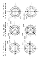
- a flexible coupling 19 which comprises (1) a hollow disk-like plate 20A located on the wheel 2 side and connected to the wheel 2, (2) a hollow disk-like plate 20C located on the motor 3 side and connected to the rotary case 3b of the motor 3, and (3) a hollow disk-like plate 20B having a plurality of direct-acting guides 19A and 19B at the same positions on the front and back sides of the motor 3 side plate and the wheel 2 side plate at intervals of 90° or 180° in the circumferential direction of the plates and connected to the above hollow disk-like plate 20A by the direct-acting guide 19A and to the above hollow disk-like plate 20C by the direct-acting guide 19B as shown in Fig. 23 and Fig.
- the working direction of the direct-acting guide 19B located on the motor 3 side is 45° from the radial direction of the hollow disk-like plates 20A to 20C and the working direction of the direct-acting guide 19A located on the wheel 2 s ide is perpendicular to the working direction of the above direct-acting guide 19B.
- the non-rotary case 3a and the knuckle 5 are interconnected by a direct-acting guide unit 21 which comprises a direct-acting guide member 21a for guiding the above non-rotary case 3a in the vertical direction of the vehicle and a shock absorber 21b consisting of a damper and a spring member expanding and contracting in the working direction of this direct-acting guide member 21a.
- the non-rotary case 3a and the knuckle 5 may be interconnected by a buffer member such as the direct-acting guide unit 14 having the damper 14a as shown in Fig. 7 and Fig. 8 of the above Embodiment 1. Since the rotary case 3b and the wheel 2 are interconnected by the above driving force transmission unit in this embodiment like the above Embodiments 2 and 3, the second elastic member 13 interposed between the rotary case 3b and the wheel 2 can be omitted.
- Each of the direct-acting guides 19A consists of a guide member 19a and a guide rail 19b as shown in Fig. 24.
- four guide members 19a having a recess extending at 45° from the radial direction are disposed at intervals of 90° in the circumferential direction of the hollow disk-like plate located on the wheel 2 side (to be referred to as "wheel-side plate” hereinafter), and four guide rails 19b having a projection to be engaged with the above guide members 19a are disposed at positions corresponding to the above guide members 19a of the intermediate hollow disk-like plate (to be referred to as "intermediate plate” hereinafter) to interconnect the wheel-side plate 20A and the intermediate plate 20B by the four direct-acting guides 19A disposed at intervals of 90°.
- the non-rotary case 3a and the knuckle 5 are interconnected by the direct-acting guide unit 21 which comprises the direct-acting guide member 21a for guiding the non-rotary case 3a in the vertical direction of the vehicle and the shock absorber 21b consisting of a damper and a spring member expanding and contracting in the working direction of the direct-acting guide member 21a.
- the direct-acting guide unit 21 which comprises the direct-acting guide member 21a for guiding the non-rotary case 3a in the vertical direction of the vehicle and the shock absorber 21b consisting of a damper and a spring member expanding and contracting in the working direction of the direct-acting guide member 21a.
- the direct-acting guide 19P consists of guide members 19i and guide rails 19j as shown in Fig. 27.
- the direct-acting guide 19P consists of (1) two guide members 19i and 19i having a recess extending in the radial direction of the above first intermediate plate 20M and disposed on the first intermediate plate 20M side of the wheel-side plate 20A located on the wheel 2 side at an interval of 180° in the circumferential direction and (2) two guide rails 19j and 19j having a projection to be engaged with the above guide members 19i and 19i and disposed at positions corresponding to the above guide members 19i and 19i in the circumferential direction on the wheel-side plate 20A side of the first intermediate plate 20M.
- This direct-acting guide 19P guides the wheel-side plate 20A and the first intermediate plate 20M in the radial direction of the plates.
- the direct-acting guide 19Q consists of (1) two guide rails 19p and 19p provided on the motor-side plate 20C side of the first intermediate plate 20M at an interval of 180° at positions 90° from the above guide rails 19j and 19j in the circumferential direction and (2) two guide members 19q and 19q disposed at positions corresponding to the above guide rails 19p and 19p in the circumferential direction of the motor-side plate 20C.
- This direct-acting guide 19Q guides the motor-side plate 20C and the first intermediate plate 20M in the radial direction of the disk.
- the direct-acting guide 19R consists of two guide members 19m and 19m having a recess extending in the radial direction of the above wheel-side plate 20A and disposed on the inner side in the radial direction of the above guide members 19i and 19i at an interval of 180° at positions 90° from the above guide members 19i and 19i in the circumferential direction, and two guide rails 19n and 19n having a projection to be engaged with the above guide members 19m and 19m and disposed on the wheel-side plate 20A side of the second intermediate plate 20N at positions corresponding to the above guide members 19m and 19m in the circumferential direction.
- the direct-acting guide 19S consists of two guide rails 19r and 19r disposed at an interval of 180° at positions 90° from the above guide rails 19n and 19n in the circumferential direction on the motor-side plate 20C side of the second intermediate plate 20N and two guide members 19s and 19s having a recess to be engaged with the above guide rails 19r and 19r and disposed at positions corresponding to the above guide rails 19r and 19r in the circumferential direction of the motor-side plate 20C.
- the motor 3 turns while it is eccentric from the wheel 2 in a downward direction. Stated more specifically, motor torque is first applied to the motor-side plate 20C and this circumferential direction force applied to the motor-side plate 20C is applied to the first intermediate plate 20M through the direct-acting guide 19Q and further to the second intermediate plate 20N through the direct-acting guide 19S which operates in a direction perpendicular to the above direct-acting guide 19Q.
- the circumferential direction force applied to the above first intermediate plate 20M is applied to the wheel-side plate 20A through the direct-acting guide 19P and circumferential direction force applied to the above second intermediate plate 20N is applied to the wheel-side plate 20A through the direct-acting guide 19R which operates in a direction perpendicular to the above direct-acting guide 19P.
- the first intermediate plate 20M on the outer side turns clockwise from down to left and up eccentrically with the center point between the axis of the wheel-side plate 20A and the axis of the motor-side plate 20C as the center.
- the second intermediate plate 20N on the inner side turns clockwise from up to right and down eccentrically with the center point between the axis of the wheel-side plate 20A and the axis of the motor-side plate 20C as the center.
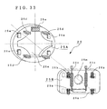
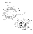
- direct-acting guides 22P and 22Q and direct-acting guides 22R and 22S whose working directions are 45° from the radial directions of the plates 20A, 20M, 20N and 20C are mounted at the same positions on the front and back sides of the above first and second intermediate plates 20M and 20N in place of the above direct-acting guides 19P and 19Q and the direct-acting guides 19R and 19S as shown in Fig.
- the direct-acting guide 22P consists of a guide member 22a and a guide rail 22b
- the direct-acting guide 22Q consists of a guide rail 22c and a guide member 22d
- the direct-acting guide 22R consists of a guide member 22e and a guide rail 22f
- the direct-acting guide 22S consists of a guide rail 22g and a guide member 22h.
- the guide members 22a and the guide members 22e are provided on the wheel-side plate 20A like the above Embodiment 4.
- the guide rails 22b are provided on the wheel-side plate 20A side of the first intermediate plate 20M, the guide rails 22c on the motor-side plate 20C side of the first intermediate plate 20M, the guide rails 22f on the wheel-side plate 20A side of the second intermediate plate 20N, the guide rails 22g on the motor-side plate 20C side of the second intermediate plate 20N, and the guide members 22d and the guide members 22h on the wheel-side plate 20C.
- the non-rotary case 3a of the inwheel motor 3 and the knuckle 5 which is a part around the wheel of the vehicle are interconnected by a buffer member such as the first elastic member 11 or the direct-acting guide unit 21 which comprises the direct-acting guide member 21a and the shock absorber 21b consisting of a spring member expanding and contracting in the working direction of the direct-acting guide member 21 and the damper.
- a buffer member such as the first elastic member 11 or the direct-acting guide unit 21 which comprises the direct-acting guide member 21a and the shock absorber 21b consisting of a spring member expanding and contracting in the working direction of the direct-acting guide member 21 and the damper.
- the above buffer units 23A and 23B may be substantially A-shaped or H-shaped link units, each comprising two arms 23m and 23n which are interconnected rotatably by a buffer member 23k consisting of a spring and/or a damper at a junction 23Z.
- a buffer member 23k consisting of a spring and/or a damper at a junction 23Z.
- one end of the buffer member 23k is fixed to an attachment member 23s attached to the above arm 23m and the other end is directly attached to the above arm 23n. Both ends of the buffer member 23k may be directly attached to the arms 23m and 23n, respectively.
- the end portions 23X of the arms 23m of the above buffer units 23A and 23B are attached to the non-rotary case 3a of the above motor 3 and the end portions 23Y of the other arms 23n are attached to the knuckle 5.
- the above buffer units 23A and 23B are attached such that the expansion or contraction direction of the above buffer member 23k becomes the vertical direction of the vehicle.
- the rotary case 3b for fixing the rotor 3R of the inwheel motor 3 and the wheel 2 are interconnected by the flexible coupling 18 (or the flexible coupling 19 or 20), and the non-rotary case 3a for fixing the stator 3S is fixed to the knuckle 5 which is a part around the wheel of the vehicle in the rotation direction and elastically supported in the vertical direction. Therefore, torque transmission efficiency from the rotary case 3b to the wheel 2 can be improved, TCFF can be further reduced, and the road holding properties of the vehicle can be enhanced.
- the above buffer unit 24 is a substantially H-shaped or A-shaped link unit which comprises two arms 24m and 24n rotatably connected to the shaft 9J by buffer members 24k consisting of a spring or damper.
- the two arms 24m and 24n are rotatably connected to the shaft 9J by the two buffer members 24k and 24k having one end connected to the shaft 9J so that the expansion or contraction direction becomes the vertical direction of the vehicle.
- the above buffer members 24k and 24k may be attached to the arms 24m and 24n by an attachment member 24s or directly.
- the non-rotary case 3a and the knuckle 5 can be interconnected such that they can move in the vertical direction of the motor 3, thereby making it possible to further reduce TCFF.
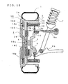
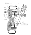
- Fig. 32 is a diagram showing the constitution of an inwheel motor system according to Embodiment 8.
- reference numeral 1 denotes a tire
- 2 denotes a wheel consisting of a rim 2a and a wheel disk 2b
- 3 denotes an inwheel motor of an outer rotor type
- 4 denotes a hub portion connected to the above wheel 2 at its rotation axis
- 5 denotes a knuckle which is a part around the wheel of a vehicle and connected to a shaft 9J
- 7 denotes a suspension member composed of a shock absorber or the like
- 8 denotes a brake mounted to the above hub portion 4
- 18 denotes a flexible coupling shown in Figs.
- Embodiment 3 which comprises hollow disk-like plates having a plurality of direct-acting guides on the front and back sides in such a manner that the working directions thereof are perpendicular to each other and which is used to interconnect the rotary case 3b for supporting the rotor 3R of the inwheel motor 3 and the wheel 2 in such a manner that they can be eccentric from each other in the radial direction of the wheel 2, and 25 denotes a buffer unit for elastically supporting the non-rotary case 3a which supports the stator 3S of the inwheel motor 3 to the knuckle 5 in the vertical direction of the vehicle.
- the rotary case 3b and the wheel 2 may be interconnected by the driving force transmission unit such as the constant-velocity universal joint 16 of the above Embodiment 2 or the flexible coupling 19 or 20 of the above Embodiment 5 or 6 in place of the above flexible coupling 18.
- the driving force transmission unit such as the constant-velocity universal joint 16 of the above Embodiment 2 or the flexible coupling 19 or 20 of the above Embodiment 5 or 6 in place of the above flexible coupling 18.
- the above buffer unit 25 comprises two plates 25A and 25B interconnected by springs 25b which operate in the vertical direction of the vehicle and whose working directions are limited to the vertical direction of the vehicle by direct-acting guides 25a and dampers 25c.
- damper attachment plate In this embodiment, four springs 25b which expand and contract in the vertical direction of the vehicle are mounted at the four corners of the plate 25B located on the suspension member 7 side (to be referred to as "knuckle attachment plate” hereinafter) and connected to the shaft 9J linked to the knuckle 5, two dampers 25c which expand and contract in the vertical direction of the vehicle are provided on both sides of a connection hole 25m for the shaft 9J formed in the center portion thereof, spring receiving portions 25d are provided at respective positions corresponding to the top and bottom portions of the above springs 25b of the plate 25A located on the motor 3 side (to be referred to as "motor attachment plate” hereinafter), a damper attachment portion 25e is provided at a position corresponding to the top portion of the above dampers 25c, that is, above a connection hole 25n for the shaft 9J, and the above plates 25A and 25B are interconnected by the four direct-acting guides 25a symmetrical about the center of the plate.
- the above motor attachment plate 25A and the knuckle attachment plate 25B are guided in the vertical direction of the vehicle by the above four direct-acting guides 25a and interconnected by the springs 25b and the dampers 25c, they can confine the inwheel motor 3 in the vertical movement direction while they generate attenuation force.
- the plates 25A and 25B are interconnected by the direct-acting guides 25a, springs 25b and dampers 25c.
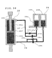
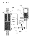
- the non-rotary case 3a for supporting the stator 3S can be fixed in the rotation direction of the wheel 2 (or the shaft 9J) with more certainty and connected such that it can move in the vertical direction of the vehicle by using a buffer unit 30 which comprises hydraulic cylinders 26 and reservoir tanks 29 connected to the hydraulic cylinders 26 by pressure hoses 27 and 28 in place of the above dampers 25c and 25c, thereby making it possible to further reduce TCFF.
- a 10 Hz or more further reduction in the level of TCFF can be achieved by increasing spring force k 4 between the motor and the part around the wheel and by reducing spring force k 3 between the inwheel motor and the car body like Example 2-3.
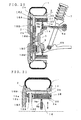
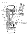
- Fig. 57 is a diagram showing the constitution of an inwheel motor system according to Embodiment 13
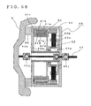
- Fig. 58 is a sectional view of the key section of the system.
- reference numeral 1 denotes a tire
- 2 denotes a wheel consisting of a rim 2a and a wheel disk 2b
- 40 denotes a geared motor (inwheel motor) which incorporates an electric motor 41 and a planetary speed reducer 42 in a motor case 43
- 4 denotes a hub portion connected to the wheel 2 at its rotation axis
- 5 denotes a knuckle which is a part around the wheel of the vehicle and connected to upper and lower suspension arms 6a and 6b
- 7 denotes a suspension member which is a shock absorber or the like
- 8 denotes a brake which is a brake disk mounted to the above hub portion 4.
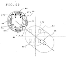
- a motor attachment unit 47 which has direct-acting guides 47k, interposed between the above elastic members 44 and 44, for guiding the motor case 43 in the vertical direction is used to interconnect the motor case 43 and the knuckle 5, thereby limiting the moving direction of the motor to the vertical direction of the wheel.
- the motor case 43 which is the non-rotary portion of the geared motor 40 is mounted to the knuckle 5 by the elastic members 44 as described above to float mount the above geared motor 40 to an unsprung mass corresponding portion which is a part around the wheel of the vehicle, the axis of the motor and the axis of the wheel can move separately in the radial direction. Therefore, the mass of the motor is separated from the unsprung mass corresponding portion of the vehicle and functions as the weight of a so-called dynamic damper like the above Embodiments 1 to 12 to cancel unsprung vibration at the time of running over an uneven road, thereby reducing TCFF.
- the motor vibrates and the axis of the motor and the axis of the wheel become eccentric from each other at the time of running over a bad road, the torque of the motor can be transmitted smoothly by using the above universal joint 45j even when these axes become eccentric from each other.
- the geared motor 40 is used as the inwheel motor in this embodiment, compared with a case where a direct drive motor of an outer rotor type is used, the capacity of the motor can be made smaller to generate the same torque and the mass of the motor can be reduced, thereby making it possible to reduce the total weight of the vehicle and the production cost of the motor. Further, since the gear ratio of the geared motor 40 can be selected, a torque curve can be freely set with the same motor, thereby improving the general-applicability of the motor compared with a direct drive motor of an outer rotor type.
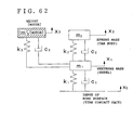
- the graph of Fig. 64 shows the analytical results of the level of TCFF in the inwheel motor system of the above Embodiment 13 and the system of the prior art using car vibration models at the time of running over an uneven road as shown in Figs. 60 to 62 and the table of Fig. 63.
- a car vibration model is a two-freedom unsprung vibration model as shown in Fig. 60 (Comparative Example 3-2 in the table of Fig. 63).
- the model is a vibration model in which the mass of the inwheel motor is added to the above unsprung mass m 1 in the vibration model in which the unsprung mass m 1 is connected to the contact face of the tire by the elastic member k 1 and the dash pot c 1 , and the above unsprung mass m 1 and the sprung mass m 2 are interconnected by the elastic member k 2 and the dash pot c 2 .
- the unsprung mass increases with the result that the level of TCFF rises and the road holding properties deteriorate as shown in Fig. 64.
- This method is more effective as the additional weight m 3 increases.
- this additional weight merely serves to increase the weight of the vehicle besides to reduce the above change, it has a bad influence on the vehicle. Therefore, there is limitation to the increase of the above weight m 3 .
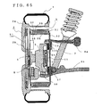
- Reference numeral 4 represents a hub portion connected to the wheel 2 at its rotation axis
- 5 represents a knuckle which is a part around the wheel of the vehicle and connected to upper and lower suspension arms 6a and 6b
- 7 represents a suspension member which is a shock absorber or the like
- 8 represents a brake which is a brake disk mounted to the above hub portion 4.
- the non-rotary case 3a is mounted to the peripheral portion of a disk-like motor attachment member 52 having a cut-out portion 52S in the center as shown in Fig. 66.
- This motor attachment member 52 is connected to a hollow oval disk-like motor vertical support member 55 having a long axis in the longitudinal direction by dampers 53 which are spring members mounted to slide guides 53G for guiding in the vertical direction of the vehicle and direct-acting guides 54 for guiding in the vertical direction of the vehicle.
- dampers 53 which are spring members mounted to slide guides 53G for guiding in the vertical direction of the vehicle and direct-acting guides 54 for guiding in the vertical direction of the vehicle.
- this motor vertical support member 55 is mounted to the knuckle 5 which is a fixed portion by elastic members 56, direct-acting guides 57 for guiding in the longitudinal direction of the vehicle and a hollow disk-like knuckle attachment member 58.
- the inwheel motor 3 since the non-rotary case 3a of the inwheel motor 3 is connected to the hollow oval disk-like motor vertical support member 55 by the dampers 53 and the direct-acting guides 54 for guiding in the vertical direction of the vehicle, the inwheel motor 3 can be float mounted to an unsprung mass corresponding portion which is a part around the wheel of the vehicle, and the axis of the motor and the axis of the wheel can move separately only in the vertical direction. Therefore, the mass of the motor is separated from the unsprung mass of the vehicle and functions as the weight of a so-called dynamic damper.
- the motor 3 the motor attachment member 52 and the motor vertical support member 55 are connected to the knuckle 5 by the elastic members 56 and the direct-acting guides 57 for guiding in the longitudinal direction of the vehicle to support the knuckle in the longitudinal direction of the vehicle, the axis of the motor and the axis of the wheel can move separately in the longitudinal direction of the vehicle as well, whereby the tire longitudinal force fluctuation can be reduced and the performance of the tire can be stabilized.
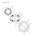
- a constant-velocity universal joint as shown in Figs. 14 and 15 of the above Embodiment 2 may be used as means of interconnecting the above rotary case 3b and the wheel 2. Since the inwheel motor 3 moves within the wheel 2 in the vertical and longitudinal directions when the rotation center of the wheel-side joint is shifted from the rotation center of the motor-side joint, torque can be smoothly transmitted even when they become eccentric from each other.
- an outer rotor type motor is used as the inwheel motor 3. Even when an inner rotor type motor 3I is used as shown in Fig. 67, the same effect can be obtained.
- the inwheel motor 3 which is a direct drive motor is mounted.
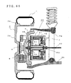
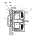
- a geared motor 40 which comprises an electric motor 41 and a speed reducing gear (planetary speed reducer) 42 in a motor case 43 shown in Figs. 57 and 58 of the above Embodiment 13 may be mounted.
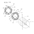
- the non-rotary motor case 43 is mounted to a hollow disk-like motor attachment member 63 by direct-acting guides 61 for guiding in the vertical direction of the vehicle and elastic members 62, and this motor attachment member 63 is mounted to the knuckle 5 which is a fixed portion by a hollow disk-like knuckle attachment member 66 by elastic members 64 and direct-acting guides 65 for guiding in the longitudinal direction of the vehicle.
- the output shaft of the speed reducing gear 42 and wheel 2 are interconnected by a shaft 45 having a universal joint 45j (see Fig. 68 and Fig. 69).
- the geared motor 40 is supported by the direct-acting guides and the elastic members in the vertical direction of the vehicle, and the vertical direction support member and the knuckle which is a part around the wheel are supported by the direct-acting guides and the elastic members in the longitudinal direction of the vehicle. Therefore, the above geared motor 30 can be float mounted to an unsprung mass corresponding portion which is a part around the wheel of the vehicle, and the axis of the motor and the axis of the wheel can move separately in the radial direction and also in the longitudinal direction of the vehicle. As a result, TCFF can be reduced, the road holding properties of the vehicle can be improved, the tire longitudinal force fluctuation can be reduced, and accordingly, the performance of the tire can be stabilized.
- the geared motor 40 is connected to the hub portion 4 by the shaft 45 having a universal joint 45j passing through the center thereof, even if the geared motor 40 moves relative to the part around the wheel, torque can be transmitted to the wheel 2 without fail.
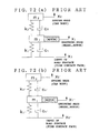
- the car vibration model is a two-freedom unsprung vibration model in which the mass of the inwheel motor is added to the unsprung mass m 1 as shown in Figs. 72(a) and 72(b) (Comparative Example 4-4).
- the motor is directly mounted to an unsprung mass corresponding portion like Comparative Example 4-4, the unsprung mass increases with the result that the level of TCFF rises and the road holding properties deteriorate as shown in Fig. 76. Also, as shown in Fig. 77, the level of tire longitudinal force fluctuation increases and the performance of the tire become unstable.
- This method is more effective as the additional weight m 3 increases.
- this additional weight merely serves to increase the weight of the vehicle besides to reduce the above change levels, it has a bad influence on the vehicle. Therefore, there is limitation to the increase of the above weight m 3 .
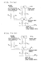
- the car vibration model is a three-freedom model (Example 4-1 of Fig. 75) in which the mass of the motor is connected to the unsprung mass m 1 by the elastic member k 3 and the dash pot c 3 as shown in Figs. 74(a) and 74(b).
- This model is obtained by removing the mass of the motor added to the unsprung mass m 1 and using this mass of the motor as additional weight m 3 for use in the dynamic damper in Figs.
- the level of TCFF and the level of tire longitudinal force fluctuation can be made equal to those of an electric car which does not employ an ordinary inwheel motor system shown in the above Comparative Example 1 without increasing the weight of the vehicle excessively.
- the elastic coefficient of the elastic member is preferably made small.
- the inwheel motor when the inwheel motor is to be mounted to the direct drive wheel, the above motor is mounted to an unsprung mass corresponding portion of the vehicle by a buffer member or buffer unit to function as the weight of a dynamic damper for the unsprung mass. Therefore, the level of TCFF at the time of running over an uneven road can be reduced, the road holding properties of the vehicle can be improved, and further a load on the inwheel motor imposed by vibration can be reduced.
- an inwheel motor vehicle having excellent space efficiency and transmission efficiency of driving force and high road holding properties can be realized.
Landscapes
- Engineering & Computer Science (AREA)
- Mechanical Engineering (AREA)
- General Engineering & Computer Science (AREA)
- Physics & Mathematics (AREA)
- Acoustics & Sound (AREA)
- Transportation (AREA)
- Chemical & Material Sciences (AREA)
- Aviation & Aerospace Engineering (AREA)
- Combustion & Propulsion (AREA)
- Electromagnetism (AREA)
- Arrangement Or Mounting Of Propulsion Units For Vehicles (AREA)
- Connection Of Motors, Electrical Generators, Mechanical Devices, And The Like (AREA)
- Motor Or Generator Frames (AREA)
- Vehicle Body Suspensions (AREA)
- Vibration Prevention Devices (AREA)
Abstract
Description
the motor is a geared motor comprising a hollow inner rotor type motor and a speed reducing gear, the non-rotary case of this geared motor and a knuckle which is a part around the wheel of a vehicle are interconnected by a buffer member, and the output shaft of the speed reducer and the wheel are linked by a shaft having a universal joint.
the motor is supported to a knuckle which is a part around the wheel of a vehicle by direct-acting guides and buffer members in the vertical direction of the vehicle and by direct-acting guides and buffer members in the longitudinal direction of the vehicle, and the rotary case of the motor and the wheel are interconnected by a flexible coupling or constant-velocity universal joint in such a manner that they can be eccentric from each other.
the motor is a geared motor comprising a hollow inner rotor type motor and a speed reducing gear, the non-rotary case of this geared motor is supported to a knuckle which is a part around the wheel by direct-acting guides and buffer members in the vertical direction and by direct-acting guides and buffer members in the longitudinal direction of the vehicle, and the output shaft of the speed reducer and the wheel are interconnected by a shaft having a universal joint.
Claims (57)
- A method of mounting an inwheel motor(3) to a direct drive wheel(2), comprising mounting the motor(3) to an unsprung mass corresponding portion(5) of a vehicle by a buffer member(11) or a buffer unit(25).
- The method of mounting an inwheel motor according to claim 1, wherein the non-rotary case(3a) of the motor (3) and a knuckle(5) are interconnected by a first elastic member(11), and the rotary case(3b) of the motor and the wheel(2) are interconnected by a second elastic member(13).
- The method of mounting an inwheel motor according to claim 1, wherein the non-rotary case(3a) of the motor for supporting the stator(3S) of the motor(3) and a knuckle(5) which is a part around the wheel of the vehicle are interconnected by a direct-acting guide unit(21), and the rotary case(3b) of the motor for supporting the rotor(3R) of the motor(3) and the wheel(5) are interconnected by a driving force transmission unit(18) which can be eccentric from the wheel(5) in the radial direction.
- The method of mounting an inwheel motor according to claim 1, wherein the non-rotary case(3a) of the motor(3) and a knuckle(5) are interconnected by a direct-acting guide unit(21) including a damper, and the rotary case(3b) of the motor and the wheel(5) are interconnected by a second elastic member(13).
- A method of mounting an inwheel motor(2) to a direct drive wheel(2), comprising mounting the non-rotary case(3a) of the motor(3) on a car body side(100) by a buffer unit(33).
- The method of mounting an inwheel motor according to any one of claims 1 to 5, wherein the motor(3) is mounted to ensure that the resonance frequency of the mounted motor should become higher than the resonance frequency of sprung mass and lower than the resonance frequency of unsprung mass.
- An inwheel motor system comprising a hollow electric motor(3) in a wheel portion to drive the wheel(2), wherein the motor(3) is mounted to an unsprung mass corresponding portion(5) of a wheel, a car body side(100), or both of them, by a buffer member(11) or a buffer unit(25).
- The inwheel motor system according to claim 7, wherein the motor(3) and the wheel(2) are interconnected by a constant-velocity universal joint(16) or by a driving force transmission unit(18) which can be eccentric from the wheel (2) in the radial direction.
- The inwheel motor system according to claim 8, wherein the driving force transmission unit(18) is a coupling unit(18) which comprises a plurality of hollow disk-like plates(18A∼18C) and direct-acting guides(18p,18q) for interconnecting adjacent plates(18A∼18C) and for guiding the adjacent plates(18A-18C) in the radial direction of the disk.
- The inwheel motor system according to any one of claims 7 to 9, wherein the non-rotary case(3a) of the motor for supporting the stator(3S) of the motor(3) and a knuckle(5) which is a part around the wheel of a vehicle are interconnected by a direct-acting guide unit(21).
- The inwheel motor system according to any one of claims 7 to 10, wherein a buffer member(11) or a buffer unit(25) is provided between the non-rotary case(3a) of the motor(3) and the knuckle(5) or/and between the rotary case(3b) and the wheel(2).
- The inwheel motor system according to claim 7, wherein the non-rotary case(3a) of the motor for supporting the stator(3S) of the motor(3) and a knuckle(5) which is a part around the wheel of the vehicle are interconnected by a first elastic member(11), and the rotary case(3b) of the motor for supporting a rotor(3R) and the wheel(2) are interconnected by a second elastic member(13).
- The inwheel motor system according to claim 12, wherein at least one or both of the first and second elastic members(11,13) are an air spring(11T,13T).
- The inwheel motor system according to claim 12, wherein the second elastic member(13) is cylindrical, one end of this cylinder(13R) is connected to the wheel(2), and the other end is connected to the rotary case(3b).
- The inwheel motor system according to claim 12, wherein the wheel(2) and the rotary case(3b) are interconnected by 16 or less board-like elastic members(13a∼13d) disposed at equal intervals in parallel to the tangent direction of the wheel.
- The inwheel motor system according to claim 15, wherein rotary joint units(13z) whose axes are in the tangent direction of the motor are provided on both end faces in the width direction of the plate-like elastic members(13a∼13d).
- The inwheel motor system according to claim 12, wherein ribs(2m) extending from the rotary case(3b) toward the wheel and ribs(2n) extending from the wheel(2) toward the rotary case are interconnected by an elastic member(15) at a plurality of sites.
- The inwheel motor system according to any one of claims 12 to 17, wherein the vertical elastic coefficient of a material constituting the first and second elastic members(11,13) is 1 to 120 MPa.
- The inwheel motor system according to any one of claims 12 to 17, wherein the vertical elastic coefficient of a material constituting the first and second elastic members(11,13) is 10 to 300 GPa.
- The inwheel motor system according to any one of claims 12 to 19, wherein the first elastic member(11) has a lower elastic modulus in the vertical direction of the vehicle than an elastic modulus in the longitudinal direction.
- The inwheel motor system according to any one of claims 12 to 20, wherein the non-rotary case(3a) is connected to the knuckle(5) by a direct-acting guide unit(14) having a spring and a damper in place of the first elastic member(11).
- The inwheel motor system according to any one of claims 12 to 21, wherein the rotary case(3b) is connected to the wheel(2) by a constant-velocity universal joint(16).
- The inwheel motor system of claim 22, wherein the second elastic member(13) is mounted at the center position of the mass of the motor(3) in the width direction of the motor.
- The inwheel motor system according to any one of claims 12 to 21, wherein the rotary case(3a) is connected to the wheel(2) by a coupling unit(18) comprising a plurality of hollow disk-like plates(18A∼18C) and direct-acting guides(18p,18q) for interconnecting adjacent plates(18A∼18C) and for guiding the adjacent plates(18A∼18C) in the radial direction of the disk.
- The inwheel motor system according to claim 7, wherein the non-rotary case(3a) of the motor for supporting the stator(3S) of the motor(3) is connected to the knuckle(5) which is a part around the wheel of the vehicle by a buffer member(11) or buffer unit(25), and the rotary case(3b) of the motor(3) is connected to the wheel(2) by a coupling unit(18) comprising a plurality of hollow disk-like plates(18A∼18C) and direct-acting guides(18p,18q) for interconnecting adjacent plates(18A∼18C) and for guiding the adjacent plates(18A∼18C) in the radial direction of the disk.
- The inwheel motor system according to claim 7, wherein the non-rotary case(3a) of the motor for supporting the stator(3S) of the motor(3) is connected to the knuckle(5) which is a part around the wheel of the vehicle by a buffer member(11) or buffer unit(25), and the rotary case(3b) of the motor(3) is connected to the wheel by a hollow disk-like plate(20A∼20C) having a plurality of direct-acting guides(19A,19B) on the motor(3) side and the wheel(2) side.
- The inwheel motor system according to claim 26, wherein the direct-acting guides(19A,19B) are disposed at the same positions on the front and back sides of the hollow disk-like plate(20A∼20C) at an interval of 90° or 180° in the circumferential direction of the plate(20A∼20C).
- The inwheel motor system according to claim 27, wherein the working directions of all the direct-acting guides(19B) on the motor(3) s ide are 45° from the radial direction of the hollow disk-like plate(20A∼20C), and the working directions of all the direct-acting guides(19A) on the wheel(3) side are perpendicular to the working directions of all the direct-acting guides(19B) on the motor(3) side.
- The inwheel motor system according to claim 7, wherein the non-rotary case(3a) of the motor for supporting the stator(3S) of the motor(3) is connected to the knuckle(5) which is a part around the wheel of the vehicle by a buffer member or a buffer unit(21), and the rotary case(3b) of the motor(3) is connected to the wheel(2) by a first hollow disk-like plate(20M) comprising a plurality of direct-acting guides(19P,19Q) on the motor side and the wheel side and by a second hollow disk-like plate(20N) disposed on the inner side of the first hollow disk-like plate(20M) and comprising a plurality of direct-acting guides(19R,19S) arranged in an opposite way to that of the first hollow disk-like plate(20M).
- The inwheel motor system according to claim 29, wherein the direct-acting guides(19P∼19S) are disposed at the same positions on the front and back sides of the first and second hollow disk-like plates(20M,20N) at an interval of 90° or 180° in the circumferential direction of the first and second hollow disk-like plates(20M,20N), the working directions of all the direct-acting guides(19Q,19S) on the motor(3) side of the first and second hollow disk-like plates(20M,20N) are 45° from the radial direction of the plates ( 20M, 20N) , and the working directions of all the direct-acting guides(19P,19R) on the wheel(3) side of the plates(20M,20N) are perpendicular to the working directions of the direct-acting guides(19Q,19S) on the motor(3) side.
- The inwheel motor system according to claim 30, wherein the mass of the first hollow disk-like plate (20M, 20N) is made equal to the mass of the second hollow disk-like plate.
- The inwheel motor system according to any one of claims 24 to 31, wherein each of the direct-acting guides(18p) consists of a guide rail(18x) having at least one recess or pro jection extending in the radial direction of the plate(18A) and of a guide member(18y) to be engaged with the guide rail(18x).
- The inwheel motor system according to claim 32, wherein steel balls(18m) are placed between the guide rail(18x) and the guide member(18y).
- The inwheel motor system according to any one of claims 24 to 31, wherein grooves extending in the radial direction are formed in the opposing sides of the plates(18A∼18C), and steel balls(18M) which can move along the grooves(18a∼18c) are placed between the plates(18A∼18C) to guide the adjacent plates(18A∼18C) in the radial direction of the disk.
- The inwheel motor system according to any one of claims 24 to 34, wherein when the number of the plates(18A∼18C) is represented by N, the plates(18A∼18C) are disposed in such a manner that the angle formed by adjacent direct-acting guides(18p,18q) or grooves(18a∼18c) in the axial direction of the plates is incremented by 180/(N-1)° from the end portion.
- The inwheel motor system according to claim 7, wherein the non-rotary case(3a) of the motor for supporting the stator(3S) of the motor(3) and a knuckle(5) which is a part around the wheel of the vehicle are interconnected by a buffer member(23A) comprising at least one pair of substantially A-shaped or H-shaped link units, each having two arms (23m, 23n) rotatably interconnected by a spring and a damper(23k), the end of one arm(23m) being connected to the non-rotary case(3a) and the end of the other arm(23n) being connected to the knuckle(5).
- The inwheel motor system according to claim 7, wherein a shaft type suspension unit is provided, and the non-rotary case(3a) of the motor for supporting the stator(3S) of the motor(3) and the shaft(9J) are interconnected by a buffer member(24) comprising at least one pair of substantially A-shaped or H-shaped link units, each having two arms(24m,24n) rotatably interconnected by a spring and a damper(24k), the end of one arm being connected to the non-rotary case(3b) and the end of the other arm being connected to the shaft(9J).
- The inwheel motor system according to claim 7, wherein the non-rotary case(3a) of the motor and a knuckle(5) are interconnected by two plates(25A,25B) whose working directions are limited to the vertical direction of the vehicle by direct-acting guides(25a), and the two plates(25A,25B) are interconnected by springs(25b) and dampers(25c) which operate in the vertical direction of the vehicle.
- The inwheel motor system according to claim 7, wherein the motor(3) is supported to a knuckle(5) which is a part around the wheel by direct-acting guides(18) and a buffer unit(30) in such a manner that it can move in the vertical direction of the vehicle, and the buffer unit(30) has valves(27m,28m) between a hydraulic cylinder(26) and a reservoir tank(29).
- The inwheel motor system according to claim 39, wherein the piston upper chamber(26a) and piston lower chamber(26b) of the hydraulic cylinder(26) are each provided with a working oil passage(27,28) having an independent valve(27m,28m) and a reservoir tank(29A,29B).
- The inwheel motor system according to claim 39, wherein the piston upper chamber (26a) and piston lower chamber(26b) of the hydraulic cylinder(26) are each provided with a working oil passage(27,28) having an independent valve(27m,28m), and the two working oil passages(27,28) are connected to a common reservoir tank(29C).
- The inwheel motor system according to claim 39, wherein the piston upper chamber(26a) and piston lower chamber(26b) of the hydraulic cylinder(26) are interconnected by working oil passages(27,28), each having an independent valve(27m,28m), and the piston lower chamber(26b) is connected to a reservoir tank(29C).
- The inwheel motor system according to any one of claims 7 to 42, wherein the hub portion(4) of the system has a connection unit(4D) with the output shaft(9) of the power engine of the vehicle.
- The inwheel motor system according to any one of claims 7 to 43, wherein the motor(3) is an outer rotor type motor(3).
- The inwheel motor system according to any one of claims 7 to 43, wherein the motor(3) is an inner rotor type motor(3I).
- An inwheel motor system having an electric motor(41) in a wheel portion to drive a wheel, wherein
the motor(40) is a geared motor(40) compris ing a hollow inner rotor type motor(41) and a speed reducing gear(42), the non-rotary case(43) of this geared motor(40) and a knuckle(5) which is a part around the wheel of a vehicle are interconnected by a buffer member(44), and the output shaft of the speed reducer(42) and the wheel(2) are linked by a shaft(45) having a universal joint(45j). - The inwheel motor system according to claim 46, wherein a direct-acting guide(47k) for guiding the motor(40) in a vertical direction is interposed between the non-rotary case(43) and the knuckle(5).
- The inwheel motor system according to claim 46, wherein the non-rotary case(3a) of the motor for supporting the stator(3S) of a hollow outer rotor type motor(3) is connected to a knuckle(5) which is a part around the wheel of a vehicle, the rotary case(3b) of the motor for supporting the rotor(3R) of the motor is connected to the wheel(2), and a wheel support unit(31) is provided on the inner side of the motor(3).
- The inwheel motor system according to claim 48, wherein the rotary case(3b) is inscribed in the wheel(2), and the knuckle(5) and the hub(4) portion of the system connected to the rotation axis of the wheel(2) are interconnected by a hub bearing(31) provided on the inner side of the hollow motor(3) to support the wheel(2).
- The inwheel motor system according to claim 48 or 49, wherein the rotary case(3b) is connected to the wheel(2) by elastic members(32).
- The inwheel motor system according to claim 50, wherein the vertical elastic coefficient of the material of the elastic members(32) is 1 to 120 MPa.
- The inwheel motor system according to any one of claims 48 to 51, wherein a brake disk(8) or brake drum is mounted to the hub portion(4).
- The inwheel motor system according to any one of claims 48 to 51, wherein the hub portion(4) of the system has a connection unit(4D) with the output shaft(9) of the power engine of the vehicle.
- An inwheel motor system having a hollow electric motor ( 3 ) in a wheel portion to drive a wheel(2), wherein
the motor(3) is supported to a knuckle(5) which is a part around the wheel of a vehicle by direct-acting guides(54) and buffer members(53) in the vertical direction of the vehicle and by direct-acting guides(57) and buffer members(56) in the longitudinal direction of the vehicle, and the rotary case(3b) of the motor and the wheel(2) are interconnected by a flexible coupling(18) or constant-velocity universal joint(18) in such a manner that they can be eccentric from each other. - The inwheel motor system according to any one of claim 54, wherein the motor(3) is an outer rotor type motor(3).
- The inwheel motor system according to any one of claim 54, wherein the motor(3) is an inner rotor type motor(3I).
- An inwheel motor system having an electric motor(40) in a wheel portion to drive a wheel(2), wherein
the motor(40) is a geared motor comprising a hollow inner rotor type motor(41) and a speed reducing gear(42), the non-rotary case(43) of this geared motor(40) is supported to a knuckle(5) which is a part around the wheel by direct-acting guides (61) and buffer members(62) in the vertical direction and by direct-acting guides (64) and buffer members (65) in the longitudinal direction of the vehicle, and the output shaft of the speed reducer(42) and the wheel(2) are interconnected by a shaft(45) having a universal joint(45j).
Applications Claiming Priority (13)
| Application Number | Priority Date | Filing Date | Title |
|---|---|---|---|
| JP2001117110 | 2001-04-16 | ||
| JP2001117110 | 2001-04-16 | ||
| JP2001132342 | 2001-04-27 | ||
| JP2001132342 | 2001-04-27 | ||
| JP2001160686 | 2001-05-29 | ||
| JP2001160686 | 2001-05-29 | ||
| JP2001314518 | 2001-10-11 | ||
| JP2001314522 | 2001-10-11 | ||
| JP2001314514 | 2001-10-11 | ||
| JP2001314518 | 2001-10-11 | ||
| JP2001314522 | 2001-10-11 | ||
| JP2001314514 | 2001-10-11 | ||
| PCT/JP2002/003730 WO2002083446A1 (en) | 2001-04-16 | 2002-04-15 | Fixing method of in-wheel motor and in-wheel motor system |
Publications (3)
| Publication Number | Publication Date |
|---|---|
| EP1380459A1 true EP1380459A1 (en) | 2004-01-14 |
| EP1380459A4 EP1380459A4 (en) | 2004-10-13 |
| EP1380459B1 EP1380459B1 (en) | 2007-01-17 |
Family
ID=27554924
Family Applications (1)
| Application Number | Title | Priority Date | Filing Date |
|---|---|---|---|
| EP02717154A Expired - Lifetime EP1380459B1 (en) | 2001-04-16 | 2002-04-15 | Fixing method of in-wheel motor and in-wheel motor system |
Country Status (7)
| Country | Link |
|---|---|
| US (1) | US7306065B2 (en) |
| EP (1) | EP1380459B1 (en) |
| JP (2) | JP3638586B2 (en) |
| CN (1) | CN100475589C (en) |
| DE (1) | DE60217661T2 (en) |
| ES (1) | ES2280523T3 (en) |
| WO (1) | WO2002083446A1 (en) |
Cited By (27)
| Publication number | Priority date | Publication date | Assignee | Title |
|---|---|---|---|---|
| WO2005030509A1 (en) * | 2003-09-30 | 2005-04-07 | Toyota Jidosha Kabushiki Kaisha | Wheel supporting apparatus improving ride comfort of vehicle |
| FR2875184A1 (en) * | 2004-09-14 | 2006-03-17 | Peugeot Citroen Automobiles Sa | Hybrid drive device for e.g. hybrid propulsion motor vehicle, has reversible rotating electrical machine integrally housed in rim of wheel and steering knuckle that concentrically traverses electrical machine |
| EP1961604A1 (en) * | 2007-02-24 | 2008-08-27 | John Deere Brasil Ltda | Drive assembly for driving a device on a soil cultivation machine |
| EP1733912A4 (en) * | 2004-04-05 | 2008-11-12 | Bridgestone Corp | VEHICLE EQUIPPED WITH ELECTRIC MOTORS INTEGRATED WITH WHEELS |
| WO2009086886A1 (en) * | 2008-01-12 | 2009-07-16 | Daimler Ag | Bearing arrangement |
| WO2009086884A1 (en) * | 2008-01-12 | 2009-07-16 | Daimler Ag | Wheel assembly |
| US7614467B2 (en) | 2003-12-22 | 2009-11-10 | Kabushiki Kaisha Bridgestone | In-wheel motor system having damping mechanism |
| US7658251B2 (en) | 2006-09-20 | 2010-02-09 | James Harry K | Direct drive electric traction motor |
| US7703780B2 (en) | 2003-09-30 | 2010-04-27 | Toyota Jidosha Kabushiki Kaisha | Wheel supporting apparatus improving ride comfort of vehicle |
| DE102009035176A1 (en) | 2009-07-29 | 2011-02-10 | Daimler Ag | Wheel hub drive for motor vehicle e.g. passenger car, has disk brake system including brake caliper that is arranged in recess, where recess is provided in stator of electric machine |
| WO2013079653A3 (en) * | 2011-12-02 | 2013-08-29 | Fraunhofer-Gesellschaft zur Förderung der angewandten Forschung e.V. | Wheel of an electric vehicle |
| ITMI20132160A1 (en) * | 2013-12-20 | 2015-06-21 | Freni Brembo Spa | WHEEL ASSEMBLY WITH MOTOR AND BRAKING DEVICE FOR A VEHICLE |
| WO2015092743A2 (en) | 2013-12-20 | 2015-06-25 | Freni Brembo S.P.A. | Wheel assembly with motor and vehicle braking device |
| DE112005001204B4 (en) * | 2004-05-25 | 2016-05-12 | Toyota Jidosha Kabushiki Kaisha | wheel support |
| US9421859B2 (en) | 2011-12-02 | 2016-08-23 | Fraunhofer-Gesellschaft Zur Forderung Der Angewandten Forschung E.V. | Fiber composite wheel with electric motor and damping |
| NL2016127B1 (en) * | 2016-01-20 | 2017-07-25 | E-Traction Europe B V | Wheel for a road vehicle. |
| CN107444007A (en) * | 2017-08-18 | 2017-12-08 | 华中科技大学 | A kind of electric wheel and vehicle with built-in suspension |
| DE102016223360A1 (en) * | 2016-11-25 | 2018-05-30 | Schaeffler Technologies AG & Co. KG | Drive arrangement for a vehicle and vehicle with the drive assembly |
| CZ307386B6 (en) * | 2015-03-06 | 2018-07-18 | Vop Cz, S.P. | An actuation and steering module of robotic wheeled vehicles |
| EP3517336A4 (en) * | 2016-09-21 | 2020-04-29 | NTN Corporation | BEARING DEVICE FOR WHEELS WITH AUXILIARY DRIVE DEVICE |
| US10752104B2 (en) | 2016-09-21 | 2020-08-25 | Ntn Corporation | Bearing device for wheels with auxiliary power device |
| IT201900015431A1 (en) * | 2019-09-03 | 2021-03-03 | Iveco Spa | DRIVE AXLE FOR A HEAVY HYBRID VEHICLE |
| CN112572374A (en) * | 2019-09-30 | 2021-03-30 | 北京中资燕京汽车有限公司 | Hub reduction gear assembly and wheel assembly |
| US20210135539A1 (en) * | 2019-11-06 | 2021-05-06 | Neapco Intellectual Property Holdings, Llc | Lubricant supported external rotor architectures |
| EP3722131A4 (en) * | 2018-03-09 | 2021-08-18 | LG Electronics Inc. | WHEEL MOTOR DRIVE UNIT |
| US20220185343A1 (en) * | 2019-03-19 | 2022-06-16 | Bombardier Transportation Gmbh | Wheel arrangement for a rail vehicle |
| US11569704B2 (en) * | 2019-05-24 | 2023-01-31 | Lg Electronics Inc. | In-wheel motor |
Families Citing this family (115)
| Publication number | Priority date | Publication date | Assignee | Title |
|---|---|---|---|---|
| JP2004274838A (en) * | 2003-03-06 | 2004-09-30 | Matsushita Electric Ind Co Ltd | Wheel drive |
| JP4225114B2 (en) * | 2003-05-14 | 2009-02-18 | トヨタ自動車株式会社 | Suspension device for electric vehicle |
| WO2004101304A1 (en) * | 2003-05-14 | 2004-11-25 | Toyota Jidosha Kabushiki Kaisha | Suspension system for electric vehicle |
| JP4225134B2 (en) * | 2003-06-25 | 2009-02-18 | トヨタ自動車株式会社 | Vehicle suspension system |
| WO2005023575A1 (en) * | 2003-09-04 | 2005-03-17 | Toyota Jidosha Kabushiki Kaisha | In-wheel motor capable of protection of speed reducer |
| JP2005081872A (en) * | 2003-09-04 | 2005-03-31 | Toyota Motor Corp | In-wheel motor |
| JP4311139B2 (en) | 2003-09-12 | 2009-08-12 | トヨタ自動車株式会社 | Wheel structure |
| JP2005114138A (en) * | 2003-10-10 | 2005-04-28 | Toyota Motor Corp | Wheel mass damper control device |
| US7237748B2 (en) * | 2003-12-15 | 2007-07-03 | Delos Aerospace, Llc | Landing gear method and apparatus for braking and maneuvering |
| JP4575298B2 (en) * | 2003-12-22 | 2010-11-04 | 株式会社ブリヂストン | In-wheel motor system |
| JP2005206140A (en) | 2003-12-24 | 2005-08-04 | Bridgestone Corp | In-wheel motor system |
| JP2005295773A (en) | 2004-04-05 | 2005-10-20 | Bridgestone Corp | Installation method of in-wheel motor |
| JP4287319B2 (en) | 2004-04-05 | 2009-07-01 | 株式会社ブリヂストン | In-wheel motor system |
| JP2005289321A (en) * | 2004-04-05 | 2005-10-20 | Bridgestone Corp | In-wheel motor installation all-wheel-drive vehicle |
| JP4276579B2 (en) * | 2004-05-17 | 2009-06-10 | トヨタ自動車株式会社 | Mounting structure of components installed in in-wheel motor |
| JP4200938B2 (en) | 2004-05-18 | 2008-12-24 | トヨタ自動車株式会社 | Electric wheel |
| JP4442315B2 (en) | 2004-05-18 | 2010-03-31 | トヨタ自動車株式会社 | Electric wheel |
| JP2006027529A (en) * | 2004-07-20 | 2006-02-02 | Toyota Motor Corp | An electric drive device for a vehicle and an automobile equipped with the same. |
| DE102004040357A1 (en) * | 2004-08-20 | 2006-02-23 | Fev Motorentechnik Gmbh | Electrical machine for vehicle, e.g. as wheel drive or regenerative brake, has stator and rotor, whereby rotor is arranged inside stator and on support for brake disk of disk brake |
| EP1817193A4 (en) * | 2004-09-09 | 2007-12-26 | Tm4 Inc | Hybrid drive train provided with hub motors |
| JP2006083895A (en) | 2004-09-14 | 2006-03-30 | Bridgestone Corp | Flexible coupling and in-wheel motor system |
| WO2006030532A1 (en) * | 2004-09-17 | 2006-03-23 | Hitachi, Ltd. | Driving gear for electric vehicle |
| US7420301B2 (en) * | 2004-10-04 | 2008-09-02 | Axletech International Ip Holdings, Llc | Wheel assembly with integral electric motor |
| US20070272458A1 (en) * | 2004-12-09 | 2007-11-29 | Kabushikikaisha Equos Research | Wheel Supporting and Driving Device |
| JP2006188153A (en) | 2005-01-06 | 2006-07-20 | Toyota Motor Corp | In-wheel motor |
| JP4986421B2 (en) * | 2005-07-11 | 2012-07-25 | 株式会社ブリヂストン | Shaft coupling and in-wheel motor system using the same |
| US20080023237A1 (en) * | 2005-09-01 | 2008-01-31 | Martin Houle | Hybrid Drive Train Provided with Hub Motors |
| GB0523069D0 (en) | 2005-11-11 | 2005-12-21 | Airbus Uk Ltd | Aircraft braking system |
| EP1961602A4 (en) * | 2005-12-12 | 2009-01-07 | Bridgestone Corp | In-wheel motor system |
| JP2007161022A (en) * | 2005-12-12 | 2007-06-28 | Bridgestone Corp | In-wheel motor system |
| JP4682045B2 (en) * | 2006-01-17 | 2011-05-11 | 株式会社ミツバ | In-wheel motor for electric vehicles |
| JP4965131B2 (en) * | 2006-01-27 | 2012-07-04 | トヨタ自動車株式会社 | In-wheel motor |
| JP4730664B2 (en) * | 2006-03-28 | 2011-07-20 | トヨタ車体株式会社 | In-wheel motor |
| JP4878965B2 (en) * | 2006-09-01 | 2012-02-15 | カヤバ工業株式会社 | In-wheel shaft coupling for electric vehicles |
| JP2008183956A (en) * | 2007-01-29 | 2008-08-14 | Mazda Motor Corp | Arrangement structure of vehicle drive device |
| JP2008207663A (en) * | 2007-02-26 | 2008-09-11 | Toyota Motor Corp | Wheel mounting structure |
| KR100875004B1 (en) | 2007-08-13 | 2008-12-19 | 주식회사 일진글로벌 | In-wheel motor mounting structure |
| KR20110014208A (en) * | 2008-05-16 | 2011-02-10 | 아메리칸 액슬 앤드 매뉴팩쳐링, 인코포레이티드 | Wheel casing with embedded rotor for hub motor |
| DE102008036560B4 (en) * | 2008-07-30 | 2010-06-17 | Sport-Service-Lorinser Sportliche Autoausrüstung GmbH | Electric wheel hub motor for motor vehicles and motor vehicles |
| JP5219718B2 (en) * | 2008-09-30 | 2013-06-26 | 株式会社ブリヂストン | In-wheel motor system |
| AU2009304587B2 (en) | 2008-10-16 | 2014-12-11 | Boorne, John Hanson | Electric motor vehicle |
| JP5272711B2 (en) * | 2008-12-22 | 2013-08-28 | トヨタ自動車株式会社 | Wheel drive device |
| JP5141614B2 (en) * | 2009-03-25 | 2013-02-13 | アイシン精機株式会社 | In-wheel motor unit |
| JP5325653B2 (en) * | 2009-05-19 | 2013-10-23 | 東海ゴム工業株式会社 | Drive unit anti-vibration holding device for electric motor drive type vehicle |
| JP2010269665A (en) * | 2009-05-20 | 2010-12-02 | Aisin Seiki Co Ltd | Wheel support device |
| US8476794B2 (en) * | 2009-05-27 | 2013-07-02 | Empire Technology Development Llc | Wheel motor with rotating outer rotor |
| US20110139523A1 (en) * | 2009-12-14 | 2011-06-16 | Chen ze-chun | In-wheel motor structure |
| JP2011240765A (en) * | 2010-05-17 | 2011-12-01 | Ntn Corp | In-wheel motor driving device |
| US9156323B2 (en) * | 2010-07-07 | 2015-10-13 | Ahmet Bugra Koku | Suspension device for a vehicle |
| DE102010040763A1 (en) * | 2010-09-14 | 2012-03-15 | Bayerische Motoren Werke Aktiengesellschaft | Independent suspension of a non-steerable driven wheel of a two-lane vehicle |
| JP5307165B2 (en) * | 2011-01-14 | 2013-10-02 | 株式会社小松製作所 | In-wheel motor |
| JP6179401B2 (en) * | 2011-03-09 | 2017-08-16 | 横浜ゴム株式会社 | Tire / wheel assembly |
| JP6145246B2 (en) * | 2011-03-09 | 2017-06-07 | 横浜ゴム株式会社 | Tire / wheel assembly |
| JP6145247B2 (en) * | 2011-03-09 | 2017-06-07 | 横浜ゴム株式会社 | Tire / wheel assembly |
| DE102011081503B4 (en) | 2011-08-24 | 2013-09-12 | Schaeffler Technologies AG & Co. KG | Wheel hub drive system |
| JP2013095309A (en) * | 2011-11-02 | 2013-05-20 | Ntn Corp | Suspension system for in-wheel motor vehicle |
| CN102555772A (en) * | 2012-01-16 | 2012-07-11 | 同济大学 | Speed reduction type hub driving system with function of power shock absorption |
| CN104290593B (en) * | 2012-01-18 | 2017-04-05 | 华南理工大学 | A kind of built-in suspension integrated form In-wheel motor driving Electric Motor Wheel |
| CN102673380B (en) * | 2012-01-18 | 2014-12-31 | 华南理工大学 | A built-in suspension integrated hub motor drives electric wheels |
| JP5872358B2 (en) * | 2012-03-30 | 2016-03-01 | 本田技研工業株式会社 | Electric vehicle |
| WO2013167114A1 (en) * | 2012-05-08 | 2013-11-14 | Ksm Castings Group Gmbh | Modular axle concept for a motor vehicle with electric drive |
| GB2487872B (en) * | 2012-05-09 | 2012-12-26 | Protean Electric Ltd | An electric motor or generator system |
| EP2851220B1 (en) * | 2012-05-14 | 2016-10-19 | Nissan Motor Co., Ltd. | Vehicle control device and vehicle control method |
| CN102673334B (en) * | 2012-05-21 | 2014-09-10 | 北京市三一重机有限公司 | Independent traveling unit and vehicle |
| CN102700372B (en) * | 2012-05-29 | 2014-09-10 | 重庆大学 | High-stability electric wheel hub |
| KR101552982B1 (en) * | 2012-07-12 | 2015-09-14 | 현대모비스 주식회사 | In-wheel motor and in-wheel working device |
| US9561715B2 (en) * | 2012-11-16 | 2017-02-07 | Deere & Company | Wheel hub with electric motor |
| DE102013003513A1 (en) * | 2013-03-04 | 2014-09-04 | Wabco Gmbh | Compressor arrangement for operating a compressed air supply system, compressed air supply system and compressed air supply system and vehicle with such a compressed air supply system |
| JP6011717B2 (en) * | 2013-04-11 | 2016-10-19 | 日産自動車株式会社 | In-wheel motor unit for vehicles |
| JP6313610B2 (en) * | 2014-02-27 | 2018-04-18 | Ntn株式会社 | CONNECTION STRUCTURE OF IN-WHEEL MOTOR DRIVE DEVICE AND DAMPER AND SUSPENSION DEVICE PROVIDED WITH THIS CONNECTION |
| CN103832234B (en) * | 2014-03-17 | 2015-10-14 | 胡建 | A kind of push-down automobile suspension system |
| DE102014210416A1 (en) * | 2014-06-03 | 2015-12-03 | Siemens Aktiengesellschaft | drive wheel |
| US9914348B2 (en) | 2014-06-30 | 2018-03-13 | Nissan North America, Inc. | Electric drive motor assembly for a wheel |
| CN105437950B (en) * | 2014-09-30 | 2019-02-15 | 上海中科深江电动车辆有限公司 | wheel drive system |
| CN105437951B (en) * | 2014-09-30 | 2018-12-07 | 上海中科深江电动车辆有限公司 | Hub drive device |
| CN104626964B (en) * | 2014-12-16 | 2017-03-08 | 武汉理工大学 | The integrated electric wheel of integrated driving, braking, suspension and turning function |
| CN104678453B (en) * | 2015-02-15 | 2017-11-21 | 山东大学 | Borehole radar antenna for tunnel geological detection detects servicing unit automatically |
| US20170028835A1 (en) * | 2015-07-29 | 2017-02-02 | William Worley | Electric Vehicle |
| JP6670571B2 (en) * | 2015-09-28 | 2020-03-25 | Ntn株式会社 | Connection structure between in-wheel motor drive device and strut type suspension device |
| CN105858407A (en) * | 2016-05-13 | 2016-08-17 | 马宏 | Luggage delivery equipment |
| JP6330861B2 (en) * | 2016-07-04 | 2018-05-30 | マツダ株式会社 | Automobile front suspension structure |
| RU2633129C1 (en) * | 2016-08-24 | 2017-10-11 | Общество с ограниченной ответственностью "Полимагнит Санкт-Петербург" | Vehicle motor wheel and vehicle with such motor wheel |
| JP6976083B2 (en) * | 2016-09-21 | 2021-12-01 | Ntn株式会社 | Vehicle power assist system and vehicle driven wheel regeneration system |
| CN107370291B (en) * | 2017-08-23 | 2019-10-18 | 东阳市俊华电器销售有限公司 | A magnetic control wheel based on electromagnetic propulsion system |
| KR101991582B1 (en) | 2017-11-23 | 2019-06-20 | 엘지전자 주식회사 | Inwheel motor driving apparatus and moving apparatus having the same |
| US10493990B2 (en) | 2017-12-15 | 2019-12-03 | Tenneco Automotive Operating Company Inc. | Systems and methods for ride control blending in electric vehicles |
| DE102018100994A1 (en) | 2018-01-17 | 2019-07-18 | Otto-Von-Guericke-Universität Magdeburg | Device for transmitting torque between a wheel and an integrated in the wheel electric machine |
| RU179573U1 (en) * | 2018-01-24 | 2018-05-17 | Акционерное общество "Машдеталь" (АО "МАШДЕТАЛЬ") | ON-BOARD VEHICLE REDUCER |
| CN112243561A (en) | 2018-06-19 | 2021-01-19 | 慕贝尔碳纤维技术有限公司 | Wheel assembly including wheel hub motor |
| JP7255383B2 (en) * | 2018-07-25 | 2023-04-11 | 株式会社デンソー | Rotating electric machine |
| DE102018126908A1 (en) * | 2018-10-29 | 2020-04-30 | Horsch Leeb Application Systems Gmbh | Independent suspension for a steerable wheel |
| CN109747363B (en) * | 2018-12-29 | 2022-06-24 | 金华恒力车业有限公司 | Independent suspension mechanism of all-terrain vehicle |
| CN109895119B (en) * | 2019-04-25 | 2021-07-20 | 哈尔滨玄智科技有限公司 | High-speed drum mechanism and combat robot |
| KR102708798B1 (en) * | 2019-06-17 | 2024-09-24 | 현대모비스 주식회사 | In-wheel working device |
| US11345320B2 (en) * | 2019-07-09 | 2022-05-31 | James A. Bentley | Magnetic brake assist, traction control and forward assist |
| US11529862B2 (en) | 2019-09-30 | 2022-12-20 | Toyota Motor Engineering & Manufacturing North America, Inc. | Systems and methods for improving propulsion of a vehicle using selectively attachable hub motors and rotatable axles |
| KR102764142B1 (en) * | 2019-10-25 | 2025-02-05 | 현대자동차주식회사 | Vehicle wheel having suspension and steering device |
| DE102020112209B4 (en) * | 2020-05-06 | 2022-03-17 | Hasse & Wrede Gmbh | Spring system with broadband isolation effect |
| EP3971051B1 (en) * | 2020-09-16 | 2026-03-25 | ALSTOM Holdings | Rail vehicle unit comprising a wheel arrangement |
| US20220176804A1 (en) * | 2020-12-07 | 2022-06-09 | Divergent Technologies, Inc. | Integrated upright and drive elements |
| CN113147364B (en) * | 2021-04-27 | 2022-10-14 | 西南交通大学 | Active vibration reduction magnetorheological suspension device used in electric wheel |
| CN113531033B (en) * | 2021-06-07 | 2022-08-26 | 杭州电子科技大学 | Electric wheel with energy recovery and multi-direction damping function |
| KR102576319B1 (en) * | 2021-08-17 | 2023-09-12 | 현대모비스 주식회사 | Disk brake apparatus of in wheel driven system |
| CN113602078A (en) * | 2021-08-25 | 2021-11-05 | 吉林大学 | Wheel assembly integrating hub motor and braking |
| CN113525068B (en) * | 2021-08-25 | 2022-04-05 | 吉林大学 | A wheel assembly with integrated braking, steering and annular in-wheel motors |
| JP7557443B2 (en) * | 2021-08-31 | 2024-09-27 | 株式会社日立製作所 | In-wheel motor |
| JP2023137044A (en) * | 2022-03-17 | 2023-09-29 | 株式会社デンソー | vehicle |
| JP2023158773A (en) * | 2022-04-19 | 2023-10-31 | 株式会社デンソー | wheel drive device |
| IT202200008270A1 (en) * | 2022-04-27 | 2023-10-27 | Ferrari Spa | WHEEL DEVICE WITH INTEGRATED ELECTRIC MOTOR FOR A MOTOR VEHICLE |
| CN115570923B (en) * | 2022-09-29 | 2025-06-03 | 吉林轮学盟科技有限公司 | A vibration reduction device for a vehicle driven by a wheel hub motor |
| DE102022132579A1 (en) * | 2022-12-07 | 2024-06-13 | Süddeutsche Gelenkscheibenfabrik Gesellschaft mit beschränkter Haftung & Co. KG. | Drive device for a vehicle wheel |
| DE102023114171A1 (en) * | 2023-05-30 | 2024-12-05 | Süddeutsche Gelenkscheibenfabrik Gesellschaft mit beschränkter Haftung & Co. KG. | transmission arrangement for vehicles |
| DE102023002373A1 (en) * | 2023-06-12 | 2024-12-12 | Mercedes-Benz Group AG | wheel hub drive device |
| DE102023002378A1 (en) * | 2023-06-12 | 2024-12-12 | Mercedes-Benz Group AG | wheel hub drive device |
| CN116872668A (en) * | 2023-06-30 | 2023-10-13 | 福州大学 | Dynamic vibration absorber for wheel hub motor driven vehicle suspension and working method thereof |
Family Cites Families (28)
| Publication number | Priority date | Publication date | Assignee | Title |
|---|---|---|---|---|
| US2581551A (en) * | 1948-04-14 | 1952-01-08 | George M Myrmirides | Means for powering vehicles |
| US2746768A (en) * | 1954-11-04 | 1956-05-22 | Gen Motors Corp | Wheel hop damper attachment for vehicle road wheels |
| GB920586A (en) | 1960-09-21 | 1963-03-06 | Bourcier Carbon Christian | Improvements in or relating to pneumatic shock absorbers |
| US3566165A (en) * | 1969-05-06 | 1971-02-23 | Gen Motors Corp | Electric vehicle drive motor |
| JPS57114032A (en) | 1980-12-29 | 1982-07-15 | Hiroshi Teramachi | Torque transfer type bearing block |
| DE3571319D1 (en) | 1984-10-08 | 1989-08-10 | Teijin Ltd | Process for producing 2,3-disubstituted -4-substituted cyclopentanones, enantiomorphs, or mixtures thereof |
| JP2517239B2 (en) | 1986-08-07 | 1996-07-24 | マツダ株式会社 | Electric car |
| US4991698A (en) | 1988-05-16 | 1991-02-12 | Bose Corporation | Damping with damping mass inside wheel |
| US5180336A (en) | 1988-09-20 | 1993-01-19 | Gutag Innovations Ag | Oldham coupling |
| JPH02266114A (en) | 1989-04-06 | 1990-10-30 | Toshiba Corp | Oldham coupling and variable air gap motor using same |
| JP2676025B2 (en) * | 1989-06-28 | 1997-11-12 | 株式会社東京アールアンドデー | Electric vehicle |
| DE4115932A1 (en) * | 1991-04-02 | 1992-12-17 | Klaue Hermann | Stub axle mounted vehicle electric drive and coupling - has electric motor connected between drive shaft and set of planetary gears and engaged by electrically operated clutches |
| DE4234831C1 (en) * | 1992-10-15 | 1994-01-05 | Siemens Ag | Drive for a vehicle wheel |
| US5327034A (en) * | 1992-07-14 | 1994-07-05 | Hydro-Quebec | Electrically motorized wheel assembly |
| DE4235697A1 (en) | 1992-09-23 | 1994-03-24 | Linde Ag | Hydromechanical drive set with incorporated epicyclic gear - which is mounted on journal, whose front side carries control face of hydraulic motor |
| JP2545733B2 (en) * | 1993-09-17 | 1996-10-23 | 環境庁国立環境研究所長 | Electric vehicle drive |
| WO1995016300A1 (en) * | 1993-12-06 | 1995-06-15 | Hydro-Quebec | Electric motor-wheel with a rotor having a housing enabling an efficient exchange of heat |
| DE4445407C1 (en) * | 1994-12-20 | 1996-02-22 | Siemens Ag | Independent wheel drive for an electrically powered vehicle |
| JP3525954B2 (en) | 1994-12-27 | 2004-05-10 | 本田技研工業株式会社 | Active engine mount device |
| EP0903835A1 (en) | 1995-04-03 | 1999-03-24 | Z&D Ltd. | Axial flow pump/marine propeller |
| DE19602119C1 (en) | 1996-01-22 | 1997-05-22 | Siemens Ag | Single wheel drive for electrically powered vehicle, esp. for low level rail vehicle, e.g. tram |
| US5894902A (en) * | 1996-09-05 | 1999-04-20 | The United States Of America As Represented By The Secretary Of The Navy | Self-propelled wheel for wheeled vehicles |
| JPH10305735A (en) * | 1997-05-07 | 1998-11-17 | Toyota Motor Corp | Wheel-in motor |
| FR2763300A1 (en) * | 1997-05-16 | 1998-11-20 | Conception & Dev Michelin Sa | VEHICLE HAVING A SUSPENSION HAVING AN ACTIVE BODY VARIATION |
| US6199652B1 (en) * | 1997-12-11 | 2001-03-13 | Vectrix Corporation | Vehicle drive wheel assembly |
| DE19858395A1 (en) | 1998-12-17 | 2000-06-21 | Thomas Viebach | Drive wheel with motor has sprung rocker arm inside rim, pivoted about axis wrt flange element, and with swinging arm to which rim is rotatably attached at distance from first axis |
| JP2000309269A (en) * | 1999-04-26 | 2000-11-07 | Mitsubishi Heavy Ind Ltd | Independent wheel drive component for rail car |
| DE60004736T2 (en) | 1999-06-29 | 2004-02-26 | Mitsubishi Heavy Industries, Ltd. | Adjustable bogie with single wheels |
-
2002
- 2002-04-15 JP JP2002581220A patent/JP3638586B2/en not_active Expired - Fee Related
- 2002-04-15 WO PCT/JP2002/003730 patent/WO2002083446A1/en not_active Ceased
- 2002-04-15 CN CNB028010930A patent/CN100475589C/en not_active Expired - Lifetime
- 2002-04-15 US US10/470,307 patent/US7306065B2/en not_active Expired - Lifetime
- 2002-04-15 DE DE60217661T patent/DE60217661T2/en not_active Expired - Lifetime
- 2002-04-15 ES ES02717154T patent/ES2280523T3/en not_active Expired - Lifetime
- 2002-04-15 EP EP02717154A patent/EP1380459B1/en not_active Expired - Lifetime
-
2003
- 2003-10-03 JP JP2003345710A patent/JP2004115014A/en active Pending
Cited By (38)
| Publication number | Priority date | Publication date | Assignee | Title |
|---|---|---|---|---|
| US7703780B2 (en) | 2003-09-30 | 2010-04-27 | Toyota Jidosha Kabushiki Kaisha | Wheel supporting apparatus improving ride comfort of vehicle |
| WO2005030509A1 (en) * | 2003-09-30 | 2005-04-07 | Toyota Jidosha Kabushiki Kaisha | Wheel supporting apparatus improving ride comfort of vehicle |
| US7614467B2 (en) | 2003-12-22 | 2009-11-10 | Kabushiki Kaisha Bridgestone | In-wheel motor system having damping mechanism |
| EP1733912A4 (en) * | 2004-04-05 | 2008-11-12 | Bridgestone Corp | VEHICLE EQUIPPED WITH ELECTRIC MOTORS INTEGRATED WITH WHEELS |
| DE112005001204B4 (en) * | 2004-05-25 | 2016-05-12 | Toyota Jidosha Kabushiki Kaisha | wheel support |
| FR2875184A1 (en) * | 2004-09-14 | 2006-03-17 | Peugeot Citroen Automobiles Sa | Hybrid drive device for e.g. hybrid propulsion motor vehicle, has reversible rotating electrical machine integrally housed in rim of wheel and steering knuckle that concentrically traverses electrical machine |
| US7658251B2 (en) | 2006-09-20 | 2010-02-09 | James Harry K | Direct drive electric traction motor |
| EP1961604A1 (en) * | 2007-02-24 | 2008-08-27 | John Deere Brasil Ltda | Drive assembly for driving a device on a soil cultivation machine |
| US7861811B2 (en) | 2007-02-24 | 2011-01-04 | Deere & Company | Ground wheel drive system for an agricultural implement |
| WO2009086886A1 (en) * | 2008-01-12 | 2009-07-16 | Daimler Ag | Bearing arrangement |
| WO2009086884A1 (en) * | 2008-01-12 | 2009-07-16 | Daimler Ag | Wheel assembly |
| DE102009035176A1 (en) | 2009-07-29 | 2011-02-10 | Daimler Ag | Wheel hub drive for motor vehicle e.g. passenger car, has disk brake system including brake caliper that is arranged in recess, where recess is provided in stator of electric machine |
| WO2013079653A3 (en) * | 2011-12-02 | 2013-08-29 | Fraunhofer-Gesellschaft zur Förderung der angewandten Forschung e.V. | Wheel of an electric vehicle |
| US9421859B2 (en) | 2011-12-02 | 2016-08-23 | Fraunhofer-Gesellschaft Zur Forderung Der Angewandten Forschung E.V. | Fiber composite wheel with electric motor and damping |
| US10047808B2 (en) | 2013-12-20 | 2018-08-14 | Freni Brembo S.P.A. | Wheel with motor and vehicle braking device |
| WO2015092743A2 (en) | 2013-12-20 | 2015-06-25 | Freni Brembo S.P.A. | Wheel assembly with motor and vehicle braking device |
| ITMI20132160A1 (en) * | 2013-12-20 | 2015-06-21 | Freni Brembo Spa | WHEEL ASSEMBLY WITH MOTOR AND BRAKING DEVICE FOR A VEHICLE |
| CZ307386B6 (en) * | 2015-03-06 | 2018-07-18 | Vop Cz, S.P. | An actuation and steering module of robotic wheeled vehicles |
| NL2016127B1 (en) * | 2016-01-20 | 2017-07-25 | E-Traction Europe B V | Wheel for a road vehicle. |
| WO2017126965A1 (en) * | 2016-01-20 | 2017-07-27 | E-Traction Europe B.V. | Wheel for a road vehicle |
| US10604002B2 (en) | 2016-01-20 | 2020-03-31 | E-Traction Europe B.V. | Wheel for a road vehicle |
| US10752104B2 (en) | 2016-09-21 | 2020-08-25 | Ntn Corporation | Bearing device for wheels with auxiliary power device |
| EP3517336A4 (en) * | 2016-09-21 | 2020-04-29 | NTN Corporation | BEARING DEVICE FOR WHEELS WITH AUXILIARY DRIVE DEVICE |
| DE102016223360A1 (en) * | 2016-11-25 | 2018-05-30 | Schaeffler Technologies AG & Co. KG | Drive arrangement for a vehicle and vehicle with the drive assembly |
| DE102016223360B4 (en) * | 2016-11-25 | 2020-10-01 | Schaeffler Technologies AG & Co. KG | Drive arrangement for a vehicle and vehicle with the drive arrangement |
| CN107444007A (en) * | 2017-08-18 | 2017-12-08 | 华中科技大学 | A kind of electric wheel and vehicle with built-in suspension |
| CN107444007B (en) * | 2017-08-18 | 2018-06-26 | 华中科技大学 | A kind of electric wheel and vehicle with built-in suspension |
| EP3722131A4 (en) * | 2018-03-09 | 2021-08-18 | LG Electronics Inc. | WHEEL MOTOR DRIVE UNIT |
| US11565582B2 (en) * | 2018-03-09 | 2023-01-31 | Lg Electronics Inc. | In-wheel motor driving apparatus |
| US20220185343A1 (en) * | 2019-03-19 | 2022-06-16 | Bombardier Transportation Gmbh | Wheel arrangement for a rail vehicle |
| US12600388B2 (en) * | 2019-03-19 | 2026-04-14 | Bombardier Transportation Gmbh | Wheel arrangement for a rail vehicle |
| US11569704B2 (en) * | 2019-05-24 | 2023-01-31 | Lg Electronics Inc. | In-wheel motor |
| IT201900015431A1 (en) * | 2019-09-03 | 2021-03-03 | Iveco Spa | DRIVE AXLE FOR A HEAVY HYBRID VEHICLE |
| EP3789218A1 (en) * | 2019-09-03 | 2021-03-10 | Iveco S.p.A. | Driving axle for a hybrid heavy vehicle |
| CN112572374A (en) * | 2019-09-30 | 2021-03-30 | 北京中资燕京汽车有限公司 | Hub reduction gear assembly and wheel assembly |
| US20210135539A1 (en) * | 2019-11-06 | 2021-05-06 | Neapco Intellectual Property Holdings, Llc | Lubricant supported external rotor architectures |
| WO2021092373A1 (en) * | 2019-11-06 | 2021-05-14 | Neapco Intellectual Property Holdings, Llc | Lubricant supported rotor architectures |
| US11652388B2 (en) * | 2019-11-06 | 2023-05-16 | Neapco Intellectual Property Holdings, Llc | Lubricant supported external rotor architectures |
Also Published As
| Publication number | Publication date |
|---|---|
| JP3638586B2 (en) | 2005-04-13 |
| DE60217661D1 (en) | 2007-03-08 |
| US20040099455A1 (en) | 2004-05-27 |
| JP2004115014A (en) | 2004-04-15 |
| EP1380459A4 (en) | 2004-10-13 |
| US7306065B2 (en) | 2007-12-11 |
| JPWO2002083446A1 (en) | 2004-08-05 |
| DE60217661T2 (en) | 2007-11-15 |
| WO2002083446A1 (en) | 2002-10-24 |
| ES2280523T3 (en) | 2007-09-16 |
| CN1460076A (en) | 2003-12-03 |
| CN100475589C (en) | 2009-04-08 |
| EP1380459B1 (en) | 2007-01-17 |
Similar Documents
| Publication | Publication Date | Title |
|---|---|---|
| EP1380459A1 (en) | Fixing method of in-wheel motor and in-wheel motor system | |
| US7287611B2 (en) | In-wheel motor system | |
| US8453774B2 (en) | In-wheel motor system for a steering wheel | |
| US7766110B2 (en) | Vehicle having in-wheel motors | |
| KR100748475B1 (en) | Wheel supporting apparatus improving ride comfort of vehicle | |
| US7703780B2 (en) | Wheel supporting apparatus improving ride comfort of vehicle | |
| US20090133944A1 (en) | In-wheel motor system | |
| CN102395484A (en) | Drive unit vibration isolation and holding device for motor-driven vehicles | |
| WO2006030715A1 (en) | Flexible coupling and in-wheel motor system | |
| JP2005289321A (en) | In-wheel motor installation all-wheel-drive vehicle | |
| US7614467B2 (en) | In-wheel motor system having damping mechanism | |
| JP4133125B2 (en) | In-wheel motor system | |
| JP4607603B2 (en) | Wheel support device | |
| JP4225114B2 (en) | Suspension device for electric vehicle | |
| US7552786B2 (en) | In-wheel motor system | |
| CN108274988B (en) | Wheelside Electric Drive System with Dynamic Vibration Absorption | |
| JP2005329910A (en) | In-wheel motor system | |
| JP2007191027A (en) | In-wheel motor system | |
| JP4350591B2 (en) | In-wheel motor system | |
| JP4279213B2 (en) | In-wheel motor system | |
| JP2006213179A (en) | Vibration absorbing device for electric vehicle and electric vehicle |
Legal Events
| Date | Code | Title | Description |
|---|---|---|---|
| PUAI | Public reference made under article 153(3) epc to a published international application that has entered the european phase |
Free format text: ORIGINAL CODE: 0009012 |
|
| 17P | Request for examination filed |
Effective date: 20031010 |
|
| AK | Designated contracting states |
Kind code of ref document: A1 Designated state(s): AT BE CH CY DE DK ES FI FR GB GR IE IT LI LU MC NL PT SE TR |
|
| RIC1 | Information provided on ipc code assigned before grant |
Ipc: 7H 02K 7/08 B Ipc: 7F 16D 3/04 B Ipc: 7B 60K 17/04 B Ipc: 7B 60K 7/00 A Ipc: 7F 16F 7/104 B Ipc: 7B 60G 13/16 B Ipc: 7F 16F 15/04 B |
|
| A4 | Supplementary search report drawn up and despatched |
Effective date: 20040825 |
|
| 17Q | First examination report despatched |
Effective date: 20041206 |
|
| GRAP | Despatch of communication of intention to grant a patent |
Free format text: ORIGINAL CODE: EPIDOSNIGR1 |
|
| GRAS | Grant fee paid |
Free format text: ORIGINAL CODE: EPIDOSNIGR3 |
|
| GRAA | (expected) grant |
Free format text: ORIGINAL CODE: 0009210 |
|
| AK | Designated contracting states |
Kind code of ref document: B1 Designated state(s): DE ES FR GB IT |
|
| REG | Reference to a national code |
Ref country code: GB Ref legal event code: FG4D |
|
| REF | Corresponds to: |
Ref document number: 60217661 Country of ref document: DE Date of ref document: 20070308 Kind code of ref document: P |
|
| ET | Fr: translation filed | ||
| REG | Reference to a national code |
Ref country code: ES Ref legal event code: FG2A Ref document number: 2280523 Country of ref document: ES Kind code of ref document: T3 |
|
| PLBE | No opposition filed within time limit |
Free format text: ORIGINAL CODE: 0009261 |
|
| STAA | Information on the status of an ep patent application or granted ep patent |
Free format text: STATUS: NO OPPOSITION FILED WITHIN TIME LIMIT |
|
| 26N | No opposition filed |
Effective date: 20071018 |
|
| PGFP | Annual fee paid to national office [announced via postgrant information from national office to epo] |
Ref country code: ES Payment date: 20090513 Year of fee payment: 8 |
|
| PGFP | Annual fee paid to national office [announced via postgrant information from national office to epo] |
Ref country code: IT Payment date: 20090427 Year of fee payment: 8 |
|
| PG25 | Lapsed in a contracting state [announced via postgrant information from national office to epo] |
Ref country code: IT Free format text: LAPSE BECAUSE OF NON-PAYMENT OF DUE FEES Effective date: 20100415 |
|
| REG | Reference to a national code |
Ref country code: ES Ref legal event code: FD2A Effective date: 20110714 |
|
| PG25 | Lapsed in a contracting state [announced via postgrant information from national office to epo] |
Ref country code: ES Free format text: LAPSE BECAUSE OF NON-PAYMENT OF DUE FEES Effective date: 20110704 |
|
| PG25 | Lapsed in a contracting state [announced via postgrant information from national office to epo] |
Ref country code: ES Free format text: LAPSE BECAUSE OF NON-PAYMENT OF DUE FEES Effective date: 20100416 |
|
| PGFP | Annual fee paid to national office [announced via postgrant information from national office to epo] |
Ref country code: GB Payment date: 20120411 Year of fee payment: 11 |
|
| GBPC | Gb: european patent ceased through non-payment of renewal fee |
Effective date: 20130415 |
|
| PG25 | Lapsed in a contracting state [announced via postgrant information from national office to epo] |
Ref country code: GB Free format text: LAPSE BECAUSE OF NON-PAYMENT OF DUE FEES Effective date: 20130415 |
|
| REG | Reference to a national code |
Ref country code: FR Ref legal event code: CD Owner name: KABUSHIKI KAISHA BRIDGESTONE, JP Effective date: 20140523 Ref country code: FR Ref legal event code: CA Effective date: 20140523 |
|
| REG | Reference to a national code |
Ref country code: DE Ref legal event code: R081 Ref document number: 60217661 Country of ref document: DE Owner name: BRIDGESTONE CORPORATION, JP Free format text: FORMER OWNER: KABUSHIKI KAISHA BRIDGESTONE, TOKIO/TOKYO, JP Effective date: 20140818 |
|
| REG | Reference to a national code |
Ref country code: FR Ref legal event code: PLFP Year of fee payment: 15 |
|
| REG | Reference to a national code |
Ref country code: FR Ref legal event code: PLFP Year of fee payment: 16 |
|
| REG | Reference to a national code |
Ref country code: FR Ref legal event code: PLFP Year of fee payment: 17 |
|
| PGFP | Annual fee paid to national office [announced via postgrant information from national office to epo] |
Ref country code: DE Payment date: 20180420 Year of fee payment: 17 |
|
| REG | Reference to a national code |
Ref country code: DE Ref legal event code: R119 Ref document number: 60217661 Country of ref document: DE |
|
| PG25 | Lapsed in a contracting state [announced via postgrant information from national office to epo] |
Ref country code: DE Free format text: LAPSE BECAUSE OF NON-PAYMENT OF DUE FEES Effective date: 20191101 |
|
| PGFP | Annual fee paid to national office [announced via postgrant information from national office to epo] |
Ref country code: FR Payment date: 20210423 Year of fee payment: 20 |