JP4965131B2 - In-wheel motor - Google Patents
In-wheel motor Download PDFInfo
- Publication number
- JP4965131B2 JP4965131B2 JP2006019312A JP2006019312A JP4965131B2 JP 4965131 B2 JP4965131 B2 JP 4965131B2 JP 2006019312 A JP2006019312 A JP 2006019312A JP 2006019312 A JP2006019312 A JP 2006019312A JP 4965131 B2 JP4965131 B2 JP 4965131B2
- Authority
- JP
- Japan
- Prior art keywords
- wheel
- vehicle
- vehicle body
- ball joint
- wheel motor
- Prior art date
- Legal status (The legal status is an assumption and is not a legal conclusion. Google has not performed a legal analysis and makes no representation as to the accuracy of the status listed.)
- Expired - Fee Related
Links
Images


Classifications
-
- B—PERFORMING OPERATIONS; TRANSPORTING
- B60—VEHICLES IN GENERAL
- B60K—ARRANGEMENT OR MOUNTING OF PROPULSION UNITS OR OF TRANSMISSIONS IN VEHICLES; ARRANGEMENT OR MOUNTING OF PLURAL DIVERSE PRIME-MOVERS IN VEHICLES; AUXILIARY DRIVES FOR VEHICLES; INSTRUMENTATION OR DASHBOARDS FOR VEHICLES; ARRANGEMENTS IN CONNECTION WITH COOLING, AIR INTAKE, GAS EXHAUST OR FUEL SUPPLY OF PROPULSION UNITS IN VEHICLES
- B60K7/00—Disposition of motor in, or adjacent to, traction wheel
- B60K7/0007—Disposition of motor in, or adjacent to, traction wheel the motor being electric
-
- B—PERFORMING OPERATIONS; TRANSPORTING
- B60—VEHICLES IN GENERAL
- B60G—VEHICLE SUSPENSION ARRANGEMENTS
- B60G2204/00—Indexing codes related to suspensions per se or to auxiliary parts
- B60G2204/10—Mounting of suspension elements
- B60G2204/30—In-wheel mountings
-
- B—PERFORMING OPERATIONS; TRANSPORTING
- B60—VEHICLES IN GENERAL
- B60K—ARRANGEMENT OR MOUNTING OF PROPULSION UNITS OR OF TRANSMISSIONS IN VEHICLES; ARRANGEMENT OR MOUNTING OF PLURAL DIVERSE PRIME-MOVERS IN VEHICLES; AUXILIARY DRIVES FOR VEHICLES; INSTRUMENTATION OR DASHBOARDS FOR VEHICLES; ARRANGEMENTS IN CONNECTION WITH COOLING, AIR INTAKE, GAS EXHAUST OR FUEL SUPPLY OF PROPULSION UNITS IN VEHICLES
- B60K17/00—Arrangement or mounting of transmissions in vehicles
- B60K17/04—Arrangement or mounting of transmissions in vehicles characterised by arrangement, location, or kind of gearing
- B60K17/043—Transmission unit disposed in on near the vehicle wheel, or between the differential gear unit and the wheel
- B60K17/046—Transmission unit disposed in on near the vehicle wheel, or between the differential gear unit and the wheel with planetary gearing having orbital motion
-
- B—PERFORMING OPERATIONS; TRANSPORTING
- B60—VEHICLES IN GENERAL
- B60K—ARRANGEMENT OR MOUNTING OF PROPULSION UNITS OR OF TRANSMISSIONS IN VEHICLES; ARRANGEMENT OR MOUNTING OF PLURAL DIVERSE PRIME-MOVERS IN VEHICLES; AUXILIARY DRIVES FOR VEHICLES; INSTRUMENTATION OR DASHBOARDS FOR VEHICLES; ARRANGEMENTS IN CONNECTION WITH COOLING, AIR INTAKE, GAS EXHAUST OR FUEL SUPPLY OF PROPULSION UNITS IN VEHICLES
- B60K7/00—Disposition of motor in, or adjacent to, traction wheel
- B60K2007/0038—Disposition of motor in, or adjacent to, traction wheel the motor moving together with the wheel axle
-
- B—PERFORMING OPERATIONS; TRANSPORTING
- B60—VEHICLES IN GENERAL
- B60K—ARRANGEMENT OR MOUNTING OF PROPULSION UNITS OR OF TRANSMISSIONS IN VEHICLES; ARRANGEMENT OR MOUNTING OF PLURAL DIVERSE PRIME-MOVERS IN VEHICLES; AUXILIARY DRIVES FOR VEHICLES; INSTRUMENTATION OR DASHBOARDS FOR VEHICLES; ARRANGEMENTS IN CONNECTION WITH COOLING, AIR INTAKE, GAS EXHAUST OR FUEL SUPPLY OF PROPULSION UNITS IN VEHICLES
- B60K7/00—Disposition of motor in, or adjacent to, traction wheel
- B60K2007/0092—Disposition of motor in, or adjacent to, traction wheel the motor axle being coaxial to the wheel axle
Description
本発明は、インホイールモータに関し、特に、車輪に設けられる回転電機のトルク反力に基づく高周波の振動が車体側へ伝達されることを抑制する技術に関する。 The present invention relates to an in-wheel motor, and more particularly to a technique for suppressing high-frequency vibration based on torque reaction force of a rotating electrical machine provided on a wheel from being transmitted to a vehicle body side.
近年、環境問題対策の1つとして、モータからの駆動力により走行するハイブリッド車、燃料電池車、電気自動車などが注目されている。このような車両には駆動源としてモータが搭載され、車両の走行時においては、モータから振動および騒音が発生する場合がある。このような問題に鑑みて、たとえば、特開平5−162542号公報(特許文献1)は、電気自動車に複数の駆動用モータを搭載する場合の、車載性の向上と振動騒音低減の両立を図る電気自動車の駆動装置を開示する。この駆動装置は、複数の駆動用モータを備えた電気自動車において、モータの本体同士を制振材を介して結合したことを特徴とする。また、この駆動装置は、複数の駆動用モータを有する電気自動車において、モータの本体を制振材を介して車体へ取り付けたことを特徴とする。 In recent years, attention has been focused on hybrid vehicles, fuel cell vehicles, electric vehicles, and the like that travel with driving force from a motor as one of countermeasures for environmental problems. Such a vehicle is equipped with a motor as a drive source, and vibration and noise may be generated from the motor when the vehicle travels. In view of such a problem, for example, Japanese Patent Laid-Open No. Hei 5-162542 (Patent Document 1) seeks to improve both in-vehicle performance and reduce vibration noise when mounting a plurality of drive motors on an electric vehicle. An electric vehicle drive device is disclosed. This drive device is characterized in that, in an electric vehicle provided with a plurality of drive motors, the main bodies of the motors are coupled to each other via a damping material. Further, this drive device is characterized in that, in an electric vehicle having a plurality of drive motors, the main body of the motor is attached to the vehicle body via a damping material.
上述した公報に開示された電気自動車の駆動装置によると、電気自動車のモータ同士を結合するタイプの場合においても、相互の加振作用を抑制してその振動の伝達を小さくでき、モータの車載性の向上と振動騒音低減の両立を図り、ひいては、モータ自体の耐久性、車両の静寂性、走行安定性を向上させることが可能となる。 According to the driving device of the disclosed electric vehicles in the above publication, in the case of the type that bind the motor together of electric vehicles, it is possible to reduce the transmission of vibration to suppress the vibration action of another, in-vehicle motor Thus, it is possible to achieve both improvement in performance and reduction in vibration and noise, thereby improving the durability of the motor itself, the quietness of the vehicle, and the running stability.
また、モータを駆動源とする電気自動車としては、車体側にモータが設けられる車両ばかりでなく車輪にインホイールモータが設けられる車両が公知である。
しかしながら、インホイールモータが設けられる車両においては、インホイールモータにおいて発生した振動が車体側に伝達されるという問題がある。モータの駆動時に発生する振動および騒音は、ロータの回転あるいはギヤ噛み合いなどに起因して発生する数百Hzから数kHzの周波数帯の振動である。これらの振動は、特に車両の加速時および減速時において顕著に発生する。 However, in a vehicle provided with an in-wheel motor, there is a problem that vibration generated in the in-wheel motor is transmitted to the vehicle body side. The vibration and noise generated when the motor is driven are vibrations in a frequency band of several hundreds of Hz to several kHz due to rotation of the rotor or gear meshing. These vibrations are particularly noticeable when the vehicle is accelerating and decelerating.
インホイールモータの筐体は、ボールジョイントを介してサスペンションに取り付けられる。ボールジョイントのボールと受け皿との間には、グリスが充填されている。ボールジョイントは、車両の加速時および減速時におけるモータのトルク反力を受ける。ボールジョイントがトルク反力を受ける際に、ボールジョイント内部の受け皿あるいは壁面にボール部が接触する。ボールジョイントにおいて受け皿あるいは壁面にボール部が接触すると、インホイールモータにおいて発生した振動がサスペンション(たとえば、ロアアームおよびアッパーアーム)を介して車体側に伝達される度合が大きくなる(すなわち、振動が伝達されやすくなる)。これにより車室内に振動および振動に基づく騒音が発生するため、乗員は不快感を感じる場合がある。 The casing of the in-wheel motor is attached to the suspension via a ball joint. Grease is filled between the ball of the ball joint and the tray. The ball joint receives a torque reaction force of the motor during acceleration and deceleration of the vehicle. When the ball joint receives a torque reaction force, the ball portion comes into contact with a tray or a wall surface inside the ball joint. When the ball portion comes into contact with the tray or the wall surface at the ball joint, the degree to which the vibration generated in the in-wheel motor is transmitted to the vehicle body via the suspension (for example, the lower arm and the upper arm) is increased (that is, the vibration is transmitted). Easier). As a result, vibrations and noise based on the vibrations are generated in the passenger compartment, and the passenger may feel uncomfortable.
また、ショックアブソーバの付け根部分やサスペンションと車体との取付部分にはゴムブッシュ等の制振部材が設けられる。これにより、路面からの衝撃や振動が車内に伝達しない構造となっている。しかしながら、これらゴムブッシュは、路面からの10〜15Hz程度の振動の入力にしか対応していない。そのため、インホイールモータにおいて発生する高周波ノイズを抑制することはできない。 Further, a vibration damping member such as a rubber bush is provided at the base portion of the shock absorber and the attachment portion between the suspension and the vehicle body. Thereby, the structure is such that impacts and vibrations from the road surface are not transmitted into the vehicle. However, these rubber bushes only support input of vibration of about 10 to 15 Hz from the road surface. Therefore, high frequency noise generated in the in-wheel motor cannot be suppressed.
上述した公報に開示された電気自動車の駆動装置において、モータは制振材を介して車体側に取り付けられるものである。また、上述したように車両の加速時および減速時にインホイールモータから車体に伝達される高周波の振動を抑制する具体的な技術について何ら開示されていない。 In the electric vehicle drive device disclosed in the above-described publication, the motor is attached to the vehicle body via a vibration damping material. Further, as described above, there is no disclosure about a specific technique for suppressing high-frequency vibration transmitted from the in-wheel motor to the vehicle body when the vehicle is accelerated and decelerated.
本発明は、上述した課題を解決するためになされたものであって、その目的は、車両の加速時および減速時に車体に伝達される高周波の振動を抑制するインホイールモータを提供することである。 The present invention has been made to solve the above-described problems, and an object of the present invention is to provide an in-wheel motor that suppresses high-frequency vibrations transmitted to the vehicle body during acceleration and deceleration of the vehicle. .
第1の発明に係るインホイールモータは、車輪に駆動力を付与する回転電機と、回転電機を収納する筐体であって、車輪を回転自在に支持する回転支持部材と、回転支持部材の車体側への取付部と回転支持部材との間に設けられる制振部材とを含む。 An in-wheel motor according to a first aspect of the present invention is a rotating electrical machine that applies driving force to a wheel, a housing that houses the rotating electrical machine, a rotational support member that rotatably supports the wheel, and a vehicle body of the rotational support member And a damping member provided between the side mounting portion and the rotation support member.
第1の発明によると、回転支持部材(たとえば、回転電機の筐体)の車体側への取付部(たとえば、ボールジョイント)と回転支持部材との間には、制振部材が設けられる。たとえば、制振部材として回転電機において発生する高周波の振動を抑制する部材を用いるようにすると、車両の加速時および減速時に回転電機のトルク反力が取付部に付与されて、回転支持部材から車体側への振動の伝達の度合が取付部において大きくなったとしても、制振部材により高周波振動の車体側への伝達を抑制することができる。したがって、車両の加速時および減速時の車体に伝達される高周波の振動を抑制するインホイールモータを提供することができる。 According to the first aspect of the invention, the vibration damping member is provided between the rotation support member (for example, the casing of the rotating electrical machine) and the attachment portion (for example, the ball joint) to the vehicle body side and the rotation support member. For example, when a member that suppresses high-frequency vibrations generated in the rotating electrical machine is used as the damping member, the torque reaction force of the rotating electrical machine is applied to the mounting portion when the vehicle is accelerated and decelerated, so that Even if the degree of transmission of vibration to the side increases at the mounting portion, transmission of high-frequency vibration to the vehicle body can be suppressed by the damping member. Therefore, it is possible to provide an in-wheel motor that suppresses high-frequency vibrations transmitted to the vehicle body during vehicle acceleration and deceleration.
第2の発明に係るインホイールモータにおいては、第1の発明の構成に加えて、制振部材は、車両の加速時および減速時の回転電機のトルク反力に基づいて発生する振動のうち予め定められた周波数帯の振動を抑制する。 In the in-wheel motor according to the second aspect of the invention, in addition to the configuration of the first aspect, the damping member is preliminarily selected from among vibrations generated based on the torque reaction force of the rotating electrical machine during acceleration and deceleration of the vehicle. Suppresses vibrations in a defined frequency band.
第2の発明によると、取付部(たとえば、ボールジョイント)と回転支持部材(たとえば、回転電機の筐体)との間には、車両の加速時および減速時に回転電機のトルク反力に基づいて発生する振動のうち予め定められた周波数帯の振動を抑制する部材が設けられる。これにより、車両の加速時および減速時に回転電機のトルク反力が取付部に付与されて、回転支持部材から車体側への振動の伝達の度合が取付部において大きくなったとしても、制振部材により予め定められた周波数帯(たとえば、回転電機において発生する高周波振動の周波数帯)の振動の車体側への伝達を抑制することができる。 According to the second invention, between the mounting portion (for example, the ball joint) and the rotation support member (for example, the casing of the rotating electrical machine), based on the torque reaction force of the rotating electrical machine during acceleration and deceleration of the vehicle. A member for suppressing vibration in a predetermined frequency band among the generated vibrations is provided. As a result, even if the torque reaction force of the rotating electrical machine is applied to the mounting portion during acceleration and deceleration of the vehicle, and the degree of vibration transmission from the rotation support member to the vehicle body increases in the mounting portion, the damping member Thus, transmission of vibrations in a predetermined frequency band (for example, a frequency band of high-frequency vibration generated in a rotating electrical machine) to the vehicle body side can be suppressed.
第3の発明に係るインホイールモータにおいては、第2の発明の構成に加えて、予め定められた周波数帯は、取付部よりも車体側に設けられる制振部材が抑制する振動の周波数帯よりも高い周波数帯である。 In the in-wheel motor according to the third invention, in addition to the configuration of the second invention, the predetermined frequency band is a frequency band of vibrations suppressed by a damping member provided on the vehicle body side with respect to the mounting portion. Is also a high frequency band.
第3の発明によると、取付部(たとえば、ボールジョイント)と回転支持部材(たとえば、回転電機の筐体)との間には、取付部よりも車体側に設けられる制振部材(たとえば、路面からの10〜15Hzの振動を吸収するゴムブッシュ)よりも高い周波数帯(たとえば、回転電機において発生する高周波振動に対応する周波数帯)の振動を抑制する制振部材が設けられる。これにより、車両の加速時および減速時に回転電機のトルク反力が取付部に付与されて、回転支持部材から車体側への振動の伝達の度合が取付部において大きくなったとしても、制振部材により取付部よりも車体側に設けられる制振部材よりも高い周波数帯の振動の車体側への伝達を抑制することができる。 According to the third invention, a damping member (for example, a road surface) provided between the mounting portion (for example, a ball joint) and a rotation support member (for example, a casing of a rotating electrical machine) on the vehicle body side with respect to the mounting portion. A damping member that suppresses vibration in a higher frequency band (for example, a frequency band corresponding to high-frequency vibration generated in a rotating electrical machine) than a rubber bush that absorbs vibration of 10 to 15 Hz from is provided. As a result, even if the torque reaction force of the rotating electrical machine is applied to the mounting portion during acceleration and deceleration of the vehicle, and the degree of vibration transmission from the rotation support member to the vehicle body increases in the mounting portion, the damping member Thus, transmission of vibrations in a higher frequency band than the vibration damping member provided on the vehicle body side relative to the attachment portion to the vehicle body side can be suppressed.
第4の発明に係るインホイールモータにおいては、第1〜3のいずれかの発明の構成に加えて、制振部材は、取付部において鉛直線が通る位置から前記車両の前後方向に所定量オフセットした位置にそれぞれ設けられる。 In the in-wheel motor according to the fourth aspect of the invention, in addition to the configuration of any one of the first to third aspects, the damping member is offset by a predetermined amount in the front-rear direction of the vehicle from the position where the vertical line passes through the mounting portion. Provided at each position.
第4の発明によると、制振部材は、取付部(たとえば、ボールジョイント)において鉛直線が通る位置から車両の前後方向に所定量オフセットした位置にそれぞれ設けられる。これにより、車両の加速時および減速時に回転電機のトルク反力が取付部に付与されて、回転電機において発生した高周波振動の車体側への伝達の度合が取付部において大きくなったとしても、制振部材が伝達の度合が大きい部位に対応する位置に設けられることにより、回転支持部材から車体側に伝達される高周波振動を効果的に抑制することができる。 According to the fourth invention, the vibration damping member is provided at a position offset by a predetermined amount in the front-rear direction of the vehicle from the position where the vertical line passes in the attachment portion (for example, ball joint). As a result, even if the torque reaction force of the rotating electrical machine is applied to the mounting portion during acceleration and deceleration of the vehicle, and the degree of transmission of high-frequency vibration generated in the rotating electrical machine to the vehicle body increases, By providing the vibration member at a position corresponding to a portion where the degree of transmission is large, high-frequency vibration transmitted from the rotation support member to the vehicle body side can be effectively suppressed.
第5の発明に係るインホイールモータにおいては、第1〜4のいずれかの発明の構成に加えて、車輪は、操舵時に車輪が操舵方向に向くように回転する操舵輪である。回転支持部材には、取付部を介して車体を懸架するサスアームが設けられる。取付部は、車体に対して車輪が操舵方向に回転自在になるように回転支持部材を支持し、かつ、車体に対して車輪が上下方向に揺動自在になるように回転支持部材を支持する。 In the in-wheel motor according to the fifth invention, in addition to the configuration of any one of the first to fourth inventions, the wheel is a steered wheel that rotates so that the wheel is directed in the steering direction during steering. The rotation support member is provided with a suspension arm that suspends the vehicle body via the attachment portion. The mounting portion supports the rotation support member so that the wheel can rotate in the steering direction with respect to the vehicle body, and supports the rotation support member so that the wheel can swing in the vertical direction with respect to the vehicle body. .
第5の発明によると、取付部(たとえば、ボールジョイント)は、車体に対して車輪を操舵方向に回転自在になるように回転支持部材(たとえば、回転電機の筐体)を支持し、かつ、車体に対して車輪が上下方向に揺動自在になるように回転支持部材を支持する。このような構造を有する取付部と回転支持部材との間に制振部材を設けることにより、回転電機において生じる高周波の振動が車体に伝達されることを抑制することができる。 According to the fifth invention, the mounting portion (for example, the ball joint) supports the rotation support member (for example, the casing of the rotating electrical machine) so that the wheel is rotatable in the steering direction with respect to the vehicle body, and The rotation support member is supported so that the wheel can swing up and down with respect to the vehicle body. By providing the damping member between the mounting portion having such a structure and the rotation support member, it is possible to suppress transmission of high-frequency vibration generated in the rotating electrical machine to the vehicle body.
第6の発明に係るインホイールモータにおいては、第1〜5のいずれかの発明の構成に加えて、取付部は、ボールジョイントである。 In the in-wheel motor which concerns on 6th invention, in addition to the structure of the invention in any one of 1st-5th, an attaching part is a ball joint.
第6の発明によると、車両の加速および減速時に回転電機のトルク反力がボールジョイントに付与されて、回転支持部材から車体側へと振動の伝達の度合がボールジョイントにおいて大きくなったとしても、制振部材により回転電機において生じた高周波の振動を抑制することができる。 According to the sixth invention, even if the torque reaction force of the rotating electrical machine is applied to the ball joint during acceleration and deceleration of the vehicle, and the degree of vibration transmission from the rotation support member to the vehicle body increases in the ball joint, High-frequency vibration generated in the rotating electrical machine can be suppressed by the damping member.
以下、図面を参照しつつ、本発明の実施の形態について説明する。以下の説明では、同一の部品には同一の符号を付してある。それらの名称および機能も同じである。したがってそれらについての詳細な説明は繰り返さない。 Hereinafter, embodiments of the present invention will be described with reference to the drawings. In the following description, the same parts are denoted by the same reference numerals. Their names and functions are also the same. Therefore, detailed description thereof will not be repeated.
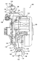
図1に本実施の形態に係るインホイールモータの正面図を示す。また、図2に本実施の形態の係るインホイールモータの車両の中央側から外側へ向けての側面図を示す。さらに、図3に本実施の形態に係るインホールモータの斜視図を示す。 FIG. 1 shows a front view of an in-wheel motor according to the present embodiment. FIG. 2 shows a side view of the in-wheel motor according to the present embodiment from the center side to the outside of the vehicle. FIG. 3 is a perspective view of the in-hole motor according to the present embodiment.
図1−図3に示すインホイールモータ100は、前輪に対応するインホイールモータであってもよいし、後輪に対応するインホイールモータであってもよく、特に限定されるものではない。本実施の形態において、インホイールモータ100は、前輪に対応するインホイールモータであるとして説明する。また、図1−図3は、左前輪側のインホイールモータの図であるが、右前輪側のインホイールモータの構成も左前輪のインホイールモータの構成と同じである。そのため、詳細な説明は繰り返さない。
The in-
本実施の形態に係るインホイールモータ100は、図1−図3に示すように、回転電機110と、回転電機110の筐体134と、ボールジョイント106,108と、ブレーキキャリパ112と、ブレーキロータ114と、制振部材124,126とから構成される。
As shown in FIGS. 1 to 3, the in-
回転電機110の筐体134の上部側には、支持部116が突設され、支持部116には、ボールジョイント106のボールジョイントソケット部130がボルト162の締結により固定される。また、筐体134の下部側には、支持部118が突設され、ボールジョイント108のボールジョイントソケット部132がボルト164の締結により固定される。ボールジョイント106は、ボールスタッド(図示せず)と、ダストブーツ152と、ボールジョイントソケット部130とから構成される。ボールジョイント106の詳細な構造については後述する。また、ボールジョイント108は、ボールスタッドと、ダストブーツ166と、ボールジョイントソケット部132とから構成される。
A
ボールジョイント106のボールスタッドは、アッパーアーム102に貫通するように組付けられて、先端のねじ山部がナット120を用いて締結される。またボールジョイント108のボールスタッドは、ロアアーム104に貫通するように組付けられて、先端のねじ山部がナット122を用いて締結される。
The ball stud of the ball joint 106 is assembled so as to penetrate the
回転電機110は、ロータとステータとから構成される。筐体134は、リダクションギヤと、回転電機110、すなわち、ロータとステータとを収納する。筐体134の内部側にステータが固設される。ステータの内側には、ロータが筐体134に設けられたベアリング等により回転自在に支持される。
The rotating
リダクションギヤは、たとえば、サンギヤ、ピニオンギヤ、リングギヤおよびプラネタリキャリアによって構成されるプラネタリギヤである。回転電機のロータにサンギヤ軸が連結される。また、プラネタリキャリアがホイールハブ(図示せず)に連結される。ホイールハブは、筐体134に設けられたハブベアリングにより回転自在に支持される。
The reduction gear is a planetary gear configured by, for example, a sun gear, a pinion gear, a ring gear, and a planetary carrier. A sun gear shaft is connected to the rotor of the rotating electrical machine. A planetary carrier is coupled to a wheel hub (not shown). The wheel hub is rotatably supported by a hub bearing provided in the
ホイールハブには、ブレーキロータ114が組付けられる。ブレーキロータ114は、ホイールハブにボルト締結により固定されてもよいし、ホイールディスクの取付時にホイールナット(あるいはボルト)の締結によりホイールディスクとホイールハブとにより挟み込まれて固定されるようにしてもよい。
A
また、筐体134には、ブレーキキャリパ112がボルト締結により固定される。ブレーキキャリパ112には、1組のブレーキパッド(図示せず)が設けられる。ブレーキキャリパ112は、1組のブレーキパッドでブレーキロータ114の図1の紙面左右方向の端面である摺動面を両側から挟み込むようにして設けられる。運転者がブレーキペダルを踏込むなどしてブレーキキャリパ112に供給される油圧が上昇することにより、ブレーキパッドによるブレーキロータ114の挟持力が上昇して制動力が発現する。
In addition, the
ブレーキロータ114のホイールハブとの当接面と反対側のホイール取付面128には、タイヤが組付けられた略カップ型形状のホイールディスク(いずれも図示せず)が取り付けられる。本実施の形態において、「車輪」は、ホイールディスクとタイヤとから構成される。また、本実施の形態において、筐体134は、回転電機110を収納し、車輪を回転自在に支持する「回転支持部材」である。
An approximately cup-shaped wheel disc (not shown) with a tire assembled thereon is attached to the
本実施の形態において、インホイールモータ100は操舵輪を構成する。すなわち、筐体134には、車輪が操舵方向に向くようにボールジョイント106,108を結ぶ線を回転軸(キングピン軸)として回転させる、図示されないステアリングタイロッドが連結される。
In the present embodiment, the in-
回転電機110は、たとえば、三相交流回転電機である。回転電機110には、パワーケーブル136が電気的に接続される。パワーケーブル136は、車体側に設けられるインバータに電気的に接続される。インバータにはバッテリから直接あるいはコンバータを介して直流電力が供給される。インバータに供給された直流電力は、交流電力に変換されてパワーケーブル136を介して回転電機110に供給される。インバータから回転電機110に対して交流電力が供給されると、ステータに巻回されたコイルに磁力が発生して、磁束の流れに応じてロータは回転力を得る。すなわち、車輪を回転させる駆動力が発現する。なお、バッテリに代えてキャパシタを用いるようにしてもよい。
The rotating
図4に図2の4−4断面を示す。図4に示すように、ボールジョイント106は、ボールスタッド150と、ダストブーツ152と、ボールジョイントソケット部130とから構成される。ボールジョイントソケット部130の内部には、ボールスタッド150の一方端に形成されるボール部154がボールジョイントソケット部130から紙面上方向に抜けないように形成される受け皿156が設けられる。ボールスタッド150の他方端にはねじ山部158が形成され、アッパーアーム102を貫通してナット120により締結される。
FIG. 4 shows a 4-4 cross section of FIG. As shown in FIG. 4, the ball joint 106 includes a
ボールスタッド150は、ねじ山部158側を紙面上方向に向けて、ボールジョイントソケット部130の下方向から受け皿156が形成される開口部を貫通するようにして組付けられる。ボールスタッド150のボール部154とボールジョイントソケット部130の受け皿156との間には、グリスが充填される。また、ボールスタッド150の軸回りの、ボールジョイントソケット部130との間隙はダストブーツ152により覆われる。なお、ボールジョイント108の構造は、ボールジョイント106の構造と同様の構造である。そのため、詳細な説明は繰り返さない。
The
このようにホールスタッド150のボール部154とボールジョイントソケット部130の受け皿156とが摺動することにより、筐体が、操舵方向に回転自在に支持され、車体に対して車輪が上下方向に揺動自在になるように支持される。
By sliding the
以上のような構成を有するインホイールモータ100が設けられる車両においては、インホイールモータにおいて発生した振動が車体側に伝達される場合がある。インホイールモータが設けられる車両においては、モータの駆動時に発生する振動および騒音は、ロータの回転あるいはギヤの噛み合いなどに起因して発生する数百Hzから数kHzの周波数帯の振動である。これらの振動は、特に車両の加速時および減速時において顕著に発生する。
In a vehicle provided with the in-
これは、車両の加速時および減速時における回転電機110のトルク反力をボールジョイント106,108で受けることに起因する。ボールジョイント106,108が回転電機110のトルク反力を受ける際に、たとえば、ボールジョイント106において、ボール部154が受け皿156あるいは壁面に直接接触する場合がある。ボール部154と受け皿156とが接触すると、接触した部位において、回転電機110において発生した振動が筐体134、アッパーアーム102およびロアアーム104を介して車体側へと伝達される度合が大きくなる(伝達されやすくなる)。これにより、車室内に振動および振動に基づく騒音が発生するため、乗員は不快感を感じる場合がある。
This is due to the ball joints 106 and 108 receiving the torque reaction force of the rotating
また、ショックアブソーバの付け根部分やアッパーアーム102およびロアアーム104と車体側との取付部分にはゴムブッシュが設けられる。これにより、衝撃や振動が車内に伝達しない構造となっている。しかしながら、これらゴムブッシュは、路面からの10〜15Hz程度の振動の入力にしか対応していない。そのため、インホイールモータにおいて発生する高周波ノイズを抑制することはできない。
Further, rubber bushes are provided at the base portion of the shock absorber and the attachment portion between the
そこで、本発明は、回転電機110の車体側への取付部と筐体134との間に制振部材124,126が設けられる点に特徴を有する。本実施の形態において、図1−図3に示すように、ボールジョイント106のボールジョイントソケット部130と支持部116との間に制振部材124が設けられ、ボールジョイント108のボールジョイントソケット部132と支持部118との間に制振部材126が設けられる。
Therefore, the present invention is characterized in that damping
図4に示すように、本実施の形態において、制振部材124は、ボールジョイントソケット部130と支持部116とが間隙を有するように形成される。具体的には、制振部材124は、ボールジョイントソケット部130に対して、図4の紙面上方向に間隙を有するようシート状の部分を有する。さらに、制振部材124は、ボールジョイントソケット部130の下部の円筒形状に形成される円筒部分160の外周面を覆う中空円筒形状の部分を有する。これにより、制振部材124によりボールジョイントソケット部130と支持部116とが当接しない位置関係となる。なお、制振部材124の厚さは、略一定であってもよいし、部位に応じて厚さを変更するようにしてもよい。たとえば、車両の加速時および減速時においては、ボールジョイント106において、ボールスタッド150は、車両の前後方向で受け皿156と接触する。したがって、制振部材124の円筒部分160の外周面を覆う中空円筒形状の部分において、車両の前後方向における厚さを左右方向よりも厚くするように形成してもよい。
As shown in FIG. 4, in the present embodiment, the damping
また、制振部材126についても同様に、ボールジョイントソケット部132と支持部118とが間隙を有するように形成される。これにより、制振部材126によりボールジョイントソケット部132と支持部118とが当接しない位置関係となる。また、制振部材126についても、車両の前後方向のおける厚さを左右方向の厚さよりも厚くするように形成してもよい。
Similarly, the damping
制振部材124,126は、たとえば、ゴムや樹脂等を材質とする部材であるが、前述のゴムブッシュに対応する路面からの10〜15Hz程度の振動よりも高い周波数帯の振動の伝達を抑制(すなわち、吸収)する部材であれば特に限定されるものではない。たとえば、制振部材124,126は、制振鋼板、ハニカム材などであってもよい。本実施の形態において、制振部材124,126は、回転電機110の作動時に発生する数百Hzから数kHzの高周波の振動を吸収するゴム系の制振材である。
The damping
以上のような構造に基づく本実施の形態に係るインホイールモータの作用について説明する。 The operation of the in-wheel motor according to the present embodiment based on the above structure will be described.
インホイールモータ100を有する車両の加速時および減速時を想定する。車両の前進加速時においては、インバータから回転電機110に電力が供給されると、車輪に回転力が付与されて車両が加速を開始する。回転電機110のロータに回転力が生じるときには、ステータが固定される筐体134には、車輪の回転方向と逆方向の回転力(以下、単に加速時のトルク反力と記載する)が発現する。
Assume that the vehicle having the in-
筐体134に生じた加速時のトルク反力は、支持部116においては、アッパーアーム102に対して車両の後方側に作用し、支持部118においては、ロアアーム104に対して車両の前方側に作用する。これにより、ボールジョイント106のボールスタッド150は、受け皿156の車両の前方側の部分に接触する。ボールジョイント108のボールスタッドは、受け皿の車両の後方側の部分に接触する。このとき、ボールジョイント106のボールスタッド150と受け皿156の接触部位においては、ボールジョイントソケット部130からボールスタッド150へと振動の伝達の度合が大きくなる(振動が伝達されやすくなる)。また、ボールジョイント108における接触部位においても同様に振動の伝達の度合が大きくなる。
The torque reaction force during acceleration generated in the
一方、車両の前進減速時においては、回転電機110において回生ブレーキ等の発電が行なわれる。このとき、車両の回転方向と同方向の回転力(以下、単に減速時のトルク反力と記載する)が発現する。
On the other hand, during forward deceleration of the vehicle, the rotating
筐体134に生じた減速時のトルク反力は、支持部116においては、車両の前方側に作用し、支持部118においては、車両の後方側に作用する。これにより、ボールジョイント106のボールスタッド150は、受け皿156の車両の後方側の部分に接触する。ボールジョイント108のボールスタッドは、受け皿の車両の前方側の部分に接触する。このとき、ボールジョイント106のボールスタッド150と受け皿156の接触部位においては、ボールジョイントソケット部130からボールスタッド150へと振動の伝達の度合が大きくなる(振動が伝達されやすくなる)。また、ボールジョイント108における接触部位においても同様に振動の伝達の度合が大きくなる。
The torque reaction force during deceleration generated in the
しかしながら、回転電機110の作動により生じる高周波の振動は、筐体134から支持部116,118と伝達され、制振部材124,126によりボールジョイントソケット部130,132への伝達が抑制される。したがって、車両の加速時および減速時において、ボールジョイント106が振動の伝達の度合が大きくなったとしても、制振部材124,126により回転電機110において生じる高周波の振動の車体側への伝達が抑制される。
However, high-frequency vibration generated by the operation of the rotating
以上のようにして本実施の形態に係るインホイールモータによると、筐体の車体側への取付部であるボールジョイントと筐体との間に制振部材が設けられる。制振部材は、回転電機において発生する高周波の振動を抑制する部材である。車両の加速時および減速時に回転電機のトルク反力がボールジョイントに付与されると、ボールスタッドと受け皿が接触する部位において、支持部から車体側への振動の伝達の度合が大きくなる。しかしながら、制振部材により高周波振動の車体側への伝達を抑制することができる。したがって、車両の加速時および減速時の車体に伝達される高周波の振動を抑制するインホイールモータを提供することができる。 As described above, according to the in-wheel motor according to the present embodiment, the vibration damping member is provided between the case and the ball joint that is the attachment portion of the case to the vehicle body. The damping member is a member that suppresses high-frequency vibration generated in the rotating electrical machine. When the torque reaction force of the rotating electrical machine is applied to the ball joint at the time of acceleration and deceleration of the vehicle, the degree of transmission of vibration from the support portion to the vehicle body increases at the portion where the ball stud and the tray contact. However, transmission of high-frequency vibration to the vehicle body side can be suppressed by the damping member. Therefore, it is possible to provide an in-wheel motor that suppresses high-frequency vibrations transmitted to the vehicle body during vehicle acceleration and deceleration.
なお、本実施の形態においては、ボールジョイントソケット部と支持部とが当接しないように制振部材を設けるようにしたが、特にこれに限定されるものではなく、たとえば、加速時および減速時における車体側への振動の伝達の度合が大きい部位に対応する位置、具体的には、鉛直線が通る位置から車両の前後方向に所定量オフセットした位置に制振部材を設けるようにしてもよい。たとえば、加速時および減速時は、ボールジョイントにおいて、鉛直線が通る位置から車両の前後方向に所定量オフセットした位置でボールスタッドとボールジョイントソケット部とが接触するため、ボールジョイントソケット部と支持部との間において少なくとも車両の前後方向で当接する部分に制振部材を介在させるようにしてもよい。このようにしても、筐体から車体側に伝達される高周波の振動を抑制することができる。 In the present embodiment, the vibration damping member is provided so that the ball joint socket portion and the support portion do not come into contact with each other. However, the present invention is not particularly limited to this. For example, during acceleration and deceleration The vibration damping member may be provided at a position corresponding to a portion where the degree of vibration transmission to the vehicle body side is large, specifically, at a position offset by a predetermined amount from the position where the vertical line passes in the front-rear direction of the vehicle. . For example, when accelerating and decelerating, since the ball stud contacts the ball joint socket portion at a position offset by a predetermined amount in the front-rear direction of the vehicle from the position where the vertical line passes in the ball joint, the ball joint socket portion and the support portion A vibration damping member may be interposed at least at a portion in contact with the vehicle in the front-rear direction of the vehicle. Even in this case, high-frequency vibrations transmitted from the housing to the vehicle body side can be suppressed.
今回開示された実施の形態はすべての点で例示であって制限的なものではないと考えられるべきである。本発明の範囲は上記した説明ではなくて特許請求の範囲によって示され、特許請求の範囲と均等の意味および範囲内でのすべての変更が含まれることが意図される。 The embodiment disclosed this time should be considered as illustrative in all points and not restrictive. The scope of the present invention is defined by the terms of the claims, rather than the description above, and is intended to include any modifications within the scope and meaning equivalent to the terms of the claims.
100 インホイールモータ、102 アッパーアーム、104 ロアアーム、106,108 ボールジョイント、110 回転電機、112 ブレーキキャリパ、114 ブレーキロータ、116,118 支持部、120,122 ナット、124,126 制振部材、128 ホイール取付面、130,132 ボールジョイントソケット部、134 筐体、150 ボールスタッド、152,166 ダストブーツ、154 ボール部、156 受け皿、158 ねじ山部、160 円筒部分、162,164 ボルト。 100 in-wheel motor, 102 upper arm, 104 lower arm, 106, 108 ball joint, 110 rotating electric machine, 112 brake caliper, 114 brake rotor, 116, 118 support part, 120, 122 nut, 124, 126 damping member, 128 wheel Mounting surface, 130, 132 Ball joint socket part, 134 housing, 150 ball stud, 152,166 dust boot, 154 ball part, 156 saucer, 158 thread part, 160 cylindrical part, 162, 164 bolt.
Claims (5)
前記回転電機を収納する筐体であって、前記車輪を回転自在に支持する回転支持部材と、
前記回転支持部材の車体側への取付部と前記回転支持部材との間に設けられる第1制振部材とを含み、
前記第1制振部材は、車両の加速時および減速時の前記回転電機のトルク反力に基づいて発生する振動のうち予め定められた周波数帯の振動を抑制し、
前記予め定められた周波数帯は、前記取付部よりも車体側に設けられる第2制振部材が抑制する振動の周波数帯よりも高い周波数帯であって、
前記第1制振部材は、前記取付部を覆う部分を含み、
前記取付部を覆う前記部分は、前記車両の前後方向の厚さが前記車両の左右方向の厚さよりも大きくなるように形成される、インホイールモータ。 A rotating electric machine that applies driving force to the wheels;
A housing that houses the rotating electrical machine, and a rotation support member that rotatably supports the wheel;
Including a first damping member provided between the rotation support member mounting portion on the vehicle body side and the rotation support member;
The first damping member suppresses vibration in a predetermined frequency band among vibrations generated based on torque reaction force of the rotating electrical machine during acceleration and deceleration of the vehicle,
The predetermined frequency band is a frequency band higher than a frequency band of vibrations suppressed by a second damping member provided on the vehicle body side relative to the mounting portion,
The first vibration damping member includes a portion that covers the attachment portion,
The said part which covers the said attaching part is an in-wheel motor formed so that the thickness of the front-back direction of the said vehicle may become larger than the thickness of the left-right direction of the said vehicle.
前記取付部を覆う前記部分は、前記取付部の外周面を覆う中空円筒形状の部分である、請求項1に記載のインホイールモータ。 The mounting portion includes a cylindrical portion having a cylindrical shape,
The in-wheel motor according to claim 1, wherein the portion covering the attachment portion is a hollow cylindrical portion covering an outer peripheral surface of the attachment portion.
前記回転支持部材には、前記取付部を介して前記車体を懸架するサスアームが設けられ、
前記取付部は、前記車体に対して前記車輪が前記操舵方向に回転自在になるように前記回転支持部材を支持し、かつ、前記車体に対して前記車輪が上下方向に揺動自在になるよ
うに前記回転支持部材を支持する、請求項1〜3のいずれかに記載のインホイールモータ。 The wheel is a steering wheel that rotates so that the wheel is directed in a steering direction during steering,
The rotation support member is provided with a suspension arm that suspends the vehicle body via the attachment portion.
The mounting portion supports the rotation support member so that the wheel can rotate in the steering direction with respect to the vehicle body, and the wheel can swing in the vertical direction with respect to the vehicle body. The in-wheel motor in any one of Claims 1-3 which support the said rotation support member in the.
Priority Applications (5)
| Application Number | Priority Date | Filing Date | Title |
|---|---|---|---|
| JP2006019312A JP4965131B2 (en) | 2006-01-27 | 2006-01-27 | In-wheel motor |
| CN2007800037362A CN101374687B (en) | 2006-01-27 | 2007-01-19 | In-wheel motor |
| US12/162,227 US8020653B2 (en) | 2006-01-27 | 2007-01-19 | Vibration damping member for in-wheel motor |
| DE112007000241T DE112007000241T5 (en) | 2006-01-27 | 2007-01-19 | In-wheel motor |
| PCT/JP2007/051220 WO2007086488A1 (en) | 2006-01-27 | 2007-01-19 | In-wheel motor |
Applications Claiming Priority (1)
| Application Number | Priority Date | Filing Date | Title |
|---|---|---|---|
| JP2006019312A JP4965131B2 (en) | 2006-01-27 | 2006-01-27 | In-wheel motor |
Publications (3)
| Publication Number | Publication Date |
|---|---|
| JP2007196904A JP2007196904A (en) | 2007-08-09 |
| JP2007196904A5 JP2007196904A5 (en) | 2008-08-21 |
| JP4965131B2 true JP4965131B2 (en) | 2012-07-04 |
Family
ID=38309274
Family Applications (1)
| Application Number | Title | Priority Date | Filing Date |
|---|---|---|---|
| JP2006019312A Expired - Fee Related JP4965131B2 (en) | 2006-01-27 | 2006-01-27 | In-wheel motor |
Country Status (5)
| Country | Link |
|---|---|
| US (1) | US8020653B2 (en) |
| JP (1) | JP4965131B2 (en) |
| CN (1) | CN101374687B (en) |
| DE (1) | DE112007000241T5 (en) |
| WO (1) | WO2007086488A1 (en) |
Families Citing this family (21)
| Publication number | Priority date | Publication date | Assignee | Title |
|---|---|---|---|---|
| JP4965131B2 (en) * | 2006-01-27 | 2012-07-04 | トヨタ自動車株式会社 | In-wheel motor |
| JP4780170B2 (en) * | 2008-09-30 | 2011-09-28 | トヨタ自動車株式会社 | Vehicle motor drive device |
| CN101638052B (en) * | 2009-08-21 | 2012-01-04 | 山东大学 | Wheel assembly with integration of independent driving, steering, suspending and braking |
| FR2953773B1 (en) * | 2009-12-16 | 2012-04-27 | Michelin Soc Tech | MOTORIZED HUB COMPRISING MEANS FOR COUPLING AND DECOUPLING. |
| JP5271295B2 (en) * | 2010-02-24 | 2013-08-21 | 株式会社アドヴィックス | Brake device for vehicle |
| WO2011118696A1 (en) * | 2010-03-25 | 2011-09-29 | Ntn株式会社 | In-wheel motor-driven device |
| CN101949426B (en) * | 2010-08-27 | 2012-05-02 | 重庆长安汽车股份有限公司 | Silencer suspended structure |
| JP5604338B2 (en) * | 2011-03-07 | 2014-10-08 | Ntn株式会社 | Electric vehicle drive |
| CN102267520B (en) * | 2011-04-19 | 2013-05-15 | 宁波市镇海西门专利技术开发有限公司 | Electric bicycle |
| JP2013095309A (en) * | 2011-11-02 | 2013-05-20 | Ntn Corp | Suspension system for in-wheel motor vehicle |
| JP5857733B2 (en) | 2011-12-26 | 2016-02-10 | アイシン精機株式会社 | Vehicle braking device |
| GB2487872B (en) * | 2012-05-09 | 2012-12-26 | Protean Electric Ltd | An electric motor or generator system |
| JP6313610B2 (en) * | 2014-02-27 | 2018-04-18 | Ntn株式会社 | CONNECTION STRUCTURE OF IN-WHEEL MOTOR DRIVE DEVICE AND DAMPER AND SUSPENSION DEVICE PROVIDED WITH THIS CONNECTION |
| JP2014159275A (en) * | 2014-03-26 | 2014-09-04 | Ntn Corp | In-wheel motor driving device |
| JP6347149B2 (en) * | 2014-05-12 | 2018-06-27 | トヨタ自動車株式会社 | In-wheel motor unit |
| JP6323555B2 (en) * | 2014-06-27 | 2018-05-16 | 日産自動車株式会社 | In-spring motor vehicle unsprung power feeder |
| JP6125066B1 (en) * | 2016-03-08 | 2017-05-10 | Ntn株式会社 | In-wheel motor drive device |
| JP6918459B2 (en) * | 2016-04-06 | 2021-08-11 | Ntn株式会社 | Wiring structure of in-wheel motor power line and in-wheel motor drive |
| JP6823418B2 (en) * | 2016-09-30 | 2021-02-03 | Ntn株式会社 | In-wheel motor drive |
| JP6113348B1 (en) * | 2016-10-18 | 2017-04-12 | Ntn株式会社 | Power cable for in-wheel motor and its wiring structure / selection method |
| KR102576319B1 (en) | 2021-08-17 | 2023-09-12 | 현대모비스 주식회사 | Disk brake apparatus of in wheel driven system |
Family Cites Families (51)
| Publication number | Priority date | Publication date | Assignee | Title |
|---|---|---|---|---|
| US1171722A (en) * | 1915-04-03 | 1916-02-15 | Edgar J Hough | Shock-absorber. |
| US3147964A (en) * | 1963-04-26 | 1964-09-08 | Gen Tire & Rubber Co | Closed end-variable spring rate bushing |
| US3912296A (en) * | 1973-12-03 | 1975-10-14 | Ford Motor Co | Shock absorber mounting |
| JPS6164506A (en) * | 1984-09-05 | 1986-04-02 | Nissan Motor Co Ltd | Strut type suspension |
| JP2517239B2 (en) * | 1986-08-07 | 1996-07-24 | マツダ株式会社 | Electric car |
| US4801129A (en) * | 1987-01-20 | 1989-01-31 | Ford Motor Company | Leaf spring clamp with attachment means |
| US4880318A (en) * | 1987-01-21 | 1989-11-14 | Tokai Rubber Industries, Ltd. | Slidable vibration-isolating rubber member |
| DE4100296C1 (en) * | 1991-01-08 | 1992-06-11 | Mercedes-Benz Aktiengesellschaft, 7000 Stuttgart, De | |
| US5180180A (en) * | 1991-04-24 | 1993-01-19 | Aisin Aw Co., Ltd. | Wheel supporting apparatus |
| US5087229A (en) * | 1991-05-06 | 1992-02-11 | General Motors Corporation | Independently suspended steerable motor wheel apparatus |
| JPH0522832U (en) | 1991-09-05 | 1993-03-26 | 株式会社リズム | Anti-vibration structure of ball joint |
| JPH05162542A (en) | 1991-12-13 | 1993-06-29 | Hitachi Ltd | Drive device for electric vehicle |
| KR100367888B1 (en) * | 1996-05-10 | 2003-02-20 | 씨씨아이 가부시키가이샤 | Energy conversion composition |
| US6173997B1 (en) * | 1996-07-11 | 2001-01-16 | Advanced Polymer Technology, Inc. | Flexible entry boot |
| SE509102C2 (en) * | 1997-04-23 | 1998-12-07 | Volvo Ab | Arrangements for wheel suspension and vehicles fitted with the same arrangement |
| DE10160599A1 (en) * | 2000-12-11 | 2002-06-13 | Yokohama Rubber Co Ltd | Motor vehicle wheel and associated mounting arrangement |
| JP3440082B2 (en) * | 2001-02-19 | 2003-08-25 | 科学技術振興事業団 | In-wheel motor for electric vehicles |
| JP3899836B2 (en) * | 2001-03-30 | 2007-03-28 | 東海ゴム工業株式会社 | Cylindrical rubber mount |
| EP1380459B1 (en) * | 2001-04-16 | 2007-01-17 | Kabushiki Kaisha Bridgestone | Fixing method of in-wheel motor and in-wheel motor system |
| WO2003095261A1 (en) * | 2002-05-07 | 2003-11-20 | Kabushiki Kaisha Bridgestone | Method and device for controlling vehicle |
| CN1684851B (en) * | 2002-08-29 | 2010-05-05 | 株式会社普利司通 | In-wheel motor system |
| JP4133186B2 (en) * | 2002-10-02 | 2008-08-13 | 株式会社ブリヂストン | In-wheel motor system for steering wheels |
| DE602004023387D1 (en) * | 2003-05-14 | 2009-11-12 | Toyota Motor Co Ltd | SUSPENSION SYSTEM FOR AN ELECTRIC MOTOR VEHICLE |
| US7228928B2 (en) * | 2003-08-22 | 2007-06-12 | Toyota Jidosha Kabushiki Kaisha | In-wheel motor capable of efficiently cooling motor |
| JP2005081872A (en) * | 2003-09-04 | 2005-03-31 | Toyota Motor Corp | In-wheel motor |
| JP4311139B2 (en) * | 2003-09-12 | 2009-08-12 | トヨタ自動車株式会社 | Wheel structure |
| JP2005104166A (en) | 2003-09-26 | 2005-04-21 | Toyota Motor Corp | Wheel structure |
| JP4113506B2 (en) * | 2003-09-30 | 2008-07-09 | トヨタ自動車株式会社 | Wheel support device |
| US7703780B2 (en) * | 2003-09-30 | 2010-04-27 | Toyota Jidosha Kabushiki Kaisha | Wheel supporting apparatus improving ride comfort of vehicle |
| JP2005119548A (en) | 2003-10-17 | 2005-05-12 | Nissan Motor Co Ltd | Suspension device of electric vehicle |
| JP4306459B2 (en) * | 2004-01-13 | 2009-08-05 | トヨタ自動車株式会社 | Wheel support device |
| JP4607603B2 (en) * | 2004-01-16 | 2011-01-05 | トヨタ自動車株式会社 | Wheel support device |
| JP4474176B2 (en) * | 2004-02-25 | 2010-06-02 | トヨタ自動車株式会社 | Wheel support device |
| JP4312078B2 (en) * | 2004-02-25 | 2009-08-12 | トヨタ自動車株式会社 | Electric wheel |
| US20050194210A1 (en) * | 2004-03-08 | 2005-09-08 | The Boeing Company | Apparatus and method for aircraft cabin noise attenuation via non-obstructive particle damping |
| JP4276579B2 (en) * | 2004-05-17 | 2009-06-10 | トヨタ自動車株式会社 | Mounting structure of components installed in in-wheel motor |
| JP4200938B2 (en) * | 2004-05-18 | 2008-12-24 | トヨタ自動車株式会社 | Electric wheel |
| JP4442315B2 (en) * | 2004-05-18 | 2010-03-31 | トヨタ自動車株式会社 | Electric wheel |
| JP4139353B2 (en) * | 2004-05-25 | 2008-08-27 | トヨタ自動車株式会社 | Wheel support device |
| JP4471103B2 (en) * | 2004-10-07 | 2010-06-02 | トヨタ自動車株式会社 | Vehicle braking / driving force control device |
| JP2006188153A (en) * | 2005-01-06 | 2006-07-20 | Toyota Motor Corp | In-wheel motor |
| JP2006240429A (en) * | 2005-03-02 | 2006-09-14 | Toyota Motor Corp | Drive unit |
| JP4656998B2 (en) * | 2005-04-22 | 2011-03-23 | トヨタ自動車株式会社 | In-wheel motor cooling structure |
| JP4656999B2 (en) * | 2005-04-22 | 2011-03-23 | トヨタ自動車株式会社 | Electric wheel |
| JP2007161022A (en) * | 2005-12-12 | 2007-06-28 | Bridgestone Corp | In-wheel motor system |
| JP2007191126A (en) * | 2006-01-23 | 2007-08-02 | Bridgestone Corp | In-wheel motor system |
| JP4965131B2 (en) * | 2006-01-27 | 2012-07-04 | トヨタ自動車株式会社 | In-wheel motor |
| JP4501910B2 (en) * | 2006-08-11 | 2010-07-14 | トヨタ自動車株式会社 | In-wheel motor car |
| US20080163453A1 (en) * | 2007-01-09 | 2008-07-10 | Jerry Joseph | Bushing for suspension system |
| US20080174082A1 (en) * | 2007-01-24 | 2008-07-24 | Bunker Donald D | Lower control arm bushing |
| JP5163206B2 (en) * | 2008-03-19 | 2013-03-13 | アイシン精機株式会社 | In-wheel motor system |
-
2006
- 2006-01-27 JP JP2006019312A patent/JP4965131B2/en not_active Expired - Fee Related
-
2007
- 2007-01-19 WO PCT/JP2007/051220 patent/WO2007086488A1/en active Search and Examination
- 2007-01-19 CN CN2007800037362A patent/CN101374687B/en not_active Expired - Fee Related
- 2007-01-19 DE DE112007000241T patent/DE112007000241T5/en not_active Ceased
- 2007-01-19 US US12/162,227 patent/US8020653B2/en not_active Expired - Fee Related
Also Published As
| Publication number | Publication date |
|---|---|
| CN101374687A (en) | 2009-02-25 |
| WO2007086488A1 (en) | 2007-08-02 |
| US20090166111A1 (en) | 2009-07-02 |
| CN101374687B (en) | 2012-07-04 |
| JP2007196904A (en) | 2007-08-09 |
| US8020653B2 (en) | 2011-09-20 |
| DE112007000241T5 (en) | 2008-11-13 |
Similar Documents
| Publication | Publication Date | Title |
|---|---|---|
| JP4965131B2 (en) | In-wheel motor | |
| US7789178B2 (en) | Wheel support device | |
| JP4820189B2 (en) | Arrangement structure of vehicle wheel drive device | |
| CN1950232B (en) | Vehicle having in-wheel motor | |
| KR100932414B1 (en) | Driving wheel structure for automobile | |
| JP2007196904A5 (en) | ||
| US20120248850A1 (en) | In-wheel motor drive device | |
| US20060144626A1 (en) | In-Wheel motor with high durability | |
| CN101370680A (en) | In-wheel motor system | |
| US8556012B2 (en) | In-wheel motor vehicle | |
| WO2005097533A1 (en) | In-wheel motor system | |
| JP2004161157A (en) | Vehicle with motor | |
| CN101044035A (en) | Vehicle ground connection comprising a wheel and a suspension integrated therein | |
| WO2005061255A1 (en) | In-wheel motor system | |
| JP5540789B2 (en) | Electric vehicle battery and motor mounting structure | |
| US6808033B2 (en) | Vehicle suspension system | |
| JP5648358B2 (en) | Wheels for in-wheel motor vehicles | |
| JP2012214203A (en) | In-wheel motor driving device | |
| KR101042418B1 (en) | Wheel assmbly for an electric vehicle | |
| WO2019207985A1 (en) | Drive unit support device | |
| JP4312078B2 (en) | Electric wheel | |
| KR102501840B1 (en) | Suspension for Inwheel System Vehicle | |
| JP2008168802A (en) | Arrangement structure of vehicle drive device | |
| JP2007106151A (en) | Wheel device | |
| CN113232504B (en) | Motor, chassis structure and vehicle |
Legal Events
| Date | Code | Title | Description |
|---|---|---|---|
| A621 | Written request for application examination |
Free format text: JAPANESE INTERMEDIATE CODE: A621 Effective date: 20080515 |
|
| A521 | Written amendment |
Free format text: JAPANESE INTERMEDIATE CODE: A523 Effective date: 20080707 |
|
| A131 | Notification of reasons for refusal |
Free format text: JAPANESE INTERMEDIATE CODE: A131 Effective date: 20110510 |
|
| A521 | Written amendment |
Free format text: JAPANESE INTERMEDIATE CODE: A523 Effective date: 20110624 |
|
| A131 | Notification of reasons for refusal |
Free format text: JAPANESE INTERMEDIATE CODE: A131 Effective date: 20120110 |
|
| A521 | Written amendment |
Free format text: JAPANESE INTERMEDIATE CODE: A523 Effective date: 20120222 |
|
| TRDD | Decision of grant or rejection written | ||
| A01 | Written decision to grant a patent or to grant a registration (utility model) |
Free format text: JAPANESE INTERMEDIATE CODE: A01 Effective date: 20120313 |
|
| A01 | Written decision to grant a patent or to grant a registration (utility model) |
Free format text: JAPANESE INTERMEDIATE CODE: A01 |
|
| A61 | First payment of annual fees (during grant procedure) |
Free format text: JAPANESE INTERMEDIATE CODE: A61 Effective date: 20120329 |
|
| FPAY | Renewal fee payment (event date is renewal date of database) |
Free format text: PAYMENT UNTIL: 20150406 Year of fee payment: 3 |
|
| LAPS | Cancellation because of no payment of annual fees |