JP4607603B2 - Wheel support device - Google Patents

Wheel support device Download PDF

Info

Publication number
JP4607603B2
JP4607603B2 JP2005008224A JP2005008224A JP4607603B2 JP 4607603 B2 JP4607603 B2 JP 4607603B2 JP 2005008224 A JP2005008224 A JP 2005008224A JP 2005008224 A JP2005008224 A JP 2005008224A JP 4607603 B2 JP4607603 B2 JP 4607603B2
Authority
JP
Japan
Prior art keywords
wheel
motor
wheel motor
rotation
vehicle body
Prior art date
Legal status (The legal status is an assumption and is not a legal conclusion. Google has not performed a legal analysis and makes no representation as to the accuracy of the status listed.)
Expired - Fee Related
Application number
JP2005008224A
Other languages
Japanese (ja)
Other versions
JP2005225486A (en
Inventor
良治 水谷
史 倉田
繁一 余合
健司 原田
潤一郎 櫻井
秀悦 鈴木
裕基 戸嶋
成孝 磯谷
Current Assignee (The listed assignees may be inaccurate. Google has not performed a legal analysis and makes no representation or warranty as to the accuracy of the list.)
Toyota Motor Corp
Aisin Corp
Original Assignee
Aisin Seiki Co Ltd
Toyota Motor Corp
Aisin Corp
Priority date (The priority date is an assumption and is not a legal conclusion. Google has not performed a legal analysis and makes no representation as to the accuracy of the date listed.)
Filing date
Publication date
Application filed by Aisin Seiki Co Ltd, Toyota Motor Corp, Aisin Corp filed Critical Aisin Seiki Co Ltd
Priority to JP2005008224A priority Critical patent/JP4607603B2/en
Publication of JP2005225486A publication Critical patent/JP2005225486A/en
Application granted granted Critical
Publication of JP4607603B2 publication Critical patent/JP4607603B2/en
Expired - Fee Related legal-status Critical Current
Anticipated expiration legal-status Critical

Links

Images

Description

この発明は、車輪支持装置に関し、特に耐久性が高い車輪支持装置に関するものである。   The present invention relates to a wheel support device, and more particularly to a wheel support device having high durability.

従来のインホイールモータ駆動方式として、中空モータをモータサスペンションによって支持したものが知られている(非特許文献1)。中空モータは、車輪のホイールに連結されており、ホイールを回転させる。中空モータは、モータサスペンションによって車両の上下方向に振動可能に支持され、バネ下重量から切離される。そして、ホイールは、サスペンションアームによって車両に支持される。このインホイールモータ駆動方式においては、車輪が振動すると、中空モータは、車輪の振動をホイールを介して受け、車両の上下方向に振動する。そして、中空モータの振動は、バネ下の振動を相殺する。
特開平5−319103号公報 特開平11−170831号公報 特許第3440082号公報 長屋 豪、若尾 泰通、阿部 明彦,”ダイナミックダンパ型インホイールモータの開発”,社団法人 自動車技術会,2002年11月26日,学術講演会前刷集 No. 83-02,p9−12
As a conventional in-wheel motor drive system, a hollow motor supported by a motor suspension is known (Non-Patent Document 1). The hollow motor is connected to the wheel of the wheel and rotates the wheel. The hollow motor is supported by the motor suspension so as to vibrate in the vertical direction of the vehicle, and is separated from the unsprung weight. The wheel is supported by the vehicle by the suspension arm. In this in-wheel motor drive system, when the wheel vibrates, the hollow motor receives the vibration of the wheel through the wheel and vibrates in the vertical direction of the vehicle. The vibration of the hollow motor cancels out the unsprung vibration.
JP-A-5-319103 Japanese Patent Laid-Open No. 11-170831 Japanese Patent No. 3440082 Go Nagaya, Yasunori Wakao, Akihiko Abe, “Development of Dynamic Damper Type In-Wheel Motor”, Japan Society for Automotive Engineers, November 26, 2002, Preprint of Scientific Lecture No. 83-02, p9-12

しかし、従来のインホイールモータ駆動方式においては、車輪の回転によってモータが回転し、そのモータの回転によってモータ支持部に剪断力がかかり、モータ支持部の耐久性が低下するという問題がある。   However, in the conventional in-wheel motor drive system, there is a problem that the motor is rotated by the rotation of the wheel, the shear force is applied to the motor support by the rotation of the motor, and the durability of the motor support is reduced.

そこで、この発明は、かかる問題を解決するためになされたものであり、その目的は、耐久性が高い車輪支持装置を提供することである。   Therefore, the present invention has been made to solve such a problem, and an object thereof is to provide a wheel support device having high durability.

この発明によれば、車輪支持装置であって、車輪のホイール内に設けられたインホイールモータに取り付けられ、車輪の振動と前記インホイールモータの振動とを互いに減衰するように配置された弾性部材と、一方端が車体の上下方向に回動可能に車体に固定されたサスペンションアームと、サスペンションアームの他方端および弾性部材に連結され、車輪のホイールを回転可能に支持する回転支持部材と、一方端が前記インホイールモータに連結されるとともに、他方端が回転支持部材に連結され、車輪の回転によるインホイールモータの回転を抑制する回転抑制部材とを備える。弾性部材は、車体の進行方向の一方向側のみにインホイールモータに取り付けられる。回転抑制部材は、上記一方向側のみにインホイールモータに取り付けられる。弾性部材は、車体の進行方向から見たときに、インホイールモータとの固定点が、インホイールモータの重心を通り、かつ車体の上下方向に延在する重心線上に位置するようにインホイールモータに固定される。 According to this invention, it is a wheel support device, and is attached to an in-wheel motor provided in the wheel of the wheel, and is an elastic member disposed so as to attenuate the vibration of the wheel and the vibration of the in-wheel motor. A suspension arm fixed to the vehicle body so that one end thereof is rotatable in the vertical direction of the vehicle body, a rotation support member connected to the other end of the suspension arm and an elastic member, and rotatably supporting the wheel of the wheel, An end is connected to the in-wheel motor, and the other end is connected to a rotation support member, and includes a rotation suppression member that suppresses rotation of the in-wheel motor due to wheel rotation. The elastic member is attached to the in-wheel motor only on one direction side in the traveling direction of the vehicle body. The rotation suppressing member is attached to the in-wheel motor only on the one direction side. The elastic member is an in-wheel motor so that the fixed point with the in-wheel motor passes through the center of gravity of the in-wheel motor and is located on the center of gravity line extending in the vertical direction of the body when viewed from the traveling direction of the body. Fixed to.

好ましくは、弾性部材は、インホイールモータとの固定点を中央部として、車体の上下方向に直列に配置された一対の弾性部材と、一対の弾性部材の振動を減衰する振動減衰機構とを含む。一対の弾性部材は、各々が、インホイールモータとの固定点と回転支持部材との間に予め自然長から圧縮された状態で組み付けられるPreferably, the elastic member includes a pair of elastic members arranged in series in the vertical direction of the vehicle body with a fixed point with the in-wheel motor as a central portion, and a vibration damping mechanism for attenuating vibration of the pair of elastic members. . Each of the pair of elastic members is assembled in a state of being compressed in advance from a natural length between a fixed point with the in-wheel motor and the rotation support member .

好ましくは、インホイールモータは、動力を発生するモータと、モータにより発生された動力をホイールに伝達するモータ出力軸とを含む。モータ出力軸は、動力をホイールに伝達する等速ジョイントに連結され、かつ、モータを、モータ出力軸と等速ジョイントとの連結部分を支点として支持するPreferably, the in-wheel motor includes a motor that generates power and a motor output shaft that transmits the power generated by the motor to the wheel. The motor output shaft is connected to a constant velocity joint that transmits power to the wheel, and supports the motor with a connection portion between the motor output shaft and the constant velocity joint as a fulcrum .

この発明による車輪支持装置は、車輪の回転によるインホイールモータの回転を抑制する回転抑制部材を備えるので、車輪の回転によるインホイールモータの回転力がインホイールモータの支持部である弾性部材にかかるのが抑制され、弾性部材への剪断力が抑制される。   Since the wheel support device according to the present invention includes the rotation suppression member that suppresses the rotation of the in-wheel motor due to the rotation of the wheel, the rotational force of the in-wheel motor due to the rotation of the wheel is applied to the elastic member that is the support portion of the in-wheel motor Is suppressed, and the shearing force to the elastic member is suppressed.

したがって、この発明によれば、インホイールモータの支持部の耐久性を向上できる。すなわち、車輪支持装置の耐久性を向上できる。   Therefore, according to this invention, durability of the support part of an in-wheel motor can be improved. That is, the durability of the wheel support device can be improved.

また、この発明による車輪支持装置は、弾性部材がインホイールモータの重心を支持するようにインホイールモータに固定されるため、インホイールモータの振動を安定させることができるとともに、等速ジョイントの荷重負荷が低減される。   Further, the wheel support device according to the present invention can stabilize the vibration of the in-wheel motor and the load of the constant velocity joint since the elastic member is fixed to the in-wheel motor so as to support the center of gravity of the in-wheel motor. The load is reduced.

したがって、この発明によれば、等速ジョイントの耐久性を向上できる。すなわち、車輪支持装置の耐久性を向上できる。さらに、等速ジョイントの小型軽量化が可能となる。   Therefore, according to the present invention, the durability of the constant velocity joint can be improved. That is, the durability of the wheel support device can be improved. Furthermore, the constant velocity joint can be reduced in size and weight.

また、この発明による車輪支持装置は、弾性部材および回転抑制部材が、回転支持部材の近傍に配置されることから、インホイールモータの振動によって回転支持部材にかかる曲げ応力を低減することができる。   In the wheel support device according to the present invention, since the elastic member and the rotation suppressing member are disposed in the vicinity of the rotation support member, the bending stress applied to the rotation support member due to the vibration of the in-wheel motor can be reduced.

したがって、この発明によれば、回転支持部材の耐久性を向上できる。すなわち、車輪支持装置の耐久性を向上できる。   Therefore, according to this invention, durability of a rotation support member can be improved. That is, the durability of the wheel support device can be improved.

さらに、この発明による車輪支持装置は、弾性部材および回転抑制部材を、インホイールモータの重心線に対して車体の進行方向の少なくとも一方向にオフセットして配置することにより、インホイールモータの車体の上下方向にスペースを確保することができ、車輪支持装置の搭載性を向上できる。   Furthermore, the wheel support device according to the present invention is arranged such that the elastic member and the rotation suppressing member are offset in at least one direction of the traveling direction of the vehicle body with respect to the center of gravity line of the in-wheel motor. Space can be secured in the vertical direction, and the mountability of the wheel support device can be improved.

本発明の実施の形態について図面を参照しながら詳細に説明する。なお、図中同一または相当部分には同一符号を付してその説明は繰返さない。   Embodiments of the present invention will be described in detail with reference to the drawings. In the drawings, the same or corresponding parts are denoted by the same reference numerals and description thereof will not be repeated.

参考例1]
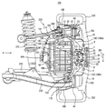
図1は、この発明の実施の形態の第1の参考例による車輪支持装置およびそれによって支持される電動輪の概略断面図である。図1を参照して、電動輪100は、ホイールディスク10と、ホイールハブ20と、等速ジョイント30と、ブレーキロータ40と、ブレーキキャリパ50と、インホイールモータIWMと、タイヤ250とを備える。
[ Reference Example 1]
FIG. 1 is a schematic cross-sectional view of a wheel support device according to a first reference example of the embodiment of the present invention and an electric wheel supported thereby. Referring to FIG. 1, electric wheel 100 includes a wheel disc 10, a wheel hub 20, a constant velocity joint 30, a brake rotor 40, a brake caliper 50, an in-wheel motor IWM, and a tire 250.

インホイールモータIWMは、ケース60と、シャフト110とを有する。また、インホイールモータIWMは、モータと、プラネタリギヤと、オイルポンプと、オイル通路とを含む。モータ、プラネタリギヤ、オイルポンプおよびオイル通路は、ケース60に収納されているため、図1においては図示されていない。   The in-wheel motor IWM has a case 60 and a shaft 110. In-wheel motor IWM includes a motor, a planetary gear, an oil pump, and an oil passage. The motor, the planetary gear, the oil pump, and the oil passage are not shown in FIG. 1 because they are housed in the case 60.

また、車輪支持装置200は、モータマウント140,150と、ボールジョイント160,170と、ナックル180と、トルクロッド190と、部材194と、アッパーアーム210と、ロアアーム220と、ショックアブソーバ230とを含む。   Wheel support device 200 includes motor mounts 140 and 150, ball joints 160 and 170, knuckle 180, torque rod 190, member 194, upper arm 210, lower arm 220, and shock absorber 230. .

ホイールディスク10は、略カップ型形状を有し、ディスク部10Aとリム部10Bとからなる。そして、ホイールディスク10は、ホイールハブ20、ブレーキロータ40、ブレーキキャリパ50、およびインホイールモータIWMを収納するようにしてもよい。ホイールディスク10は、ディスク部10Aをネジ1,2によってホイールハブ20に締結することによりホイールハブ20と連結される。ホイールハブ20は、等速ジョイント30を内蔵し、その内蔵した等速ジョイント30を介してインホイールモータIWMのシャフト110に連結される。そして、ホイールハブ20は、ハブベアリング11,12によってナックル180に回転自在に支持される。   The wheel disc 10 has a substantially cup shape, and includes a disc portion 10A and a rim portion 10B. The wheel disc 10 may house the wheel hub 20, the brake rotor 40, the brake caliper 50, and the in-wheel motor IWM. The wheel disc 10 is coupled to the wheel hub 20 by fastening the disc portion 10A to the wheel hub 20 with screws 1 and 2. The wheel hub 20 incorporates a constant velocity joint 30 and is coupled to the shaft 110 of the in-wheel motor IWM via the built-in constant velocity joint 30. The wheel hub 20 is rotatably supported by the knuckle 180 by the hub bearings 11 and 12.

等速ジョイント30は、インナー31と、ボール32とを含む。インナー31は、シャフト110に嵌合される。ボール32は、シャフト110の回転軸方向に設けられたホイールハブ20の溝とインナー31の溝とに噛合っており、シャフト110の回転に伴ってホイールハブ20を回転させる。また、ボール32は、ホイールハブ20およびインナー31に設けられた溝に沿ってシャフト110の回転軸方向に移動可能である。   The constant velocity joint 30 includes an inner 31 and a ball 32. The inner 31 is fitted to the shaft 110. The ball 32 meshes with the groove of the wheel hub 20 provided in the rotation axis direction of the shaft 110 and the groove of the inner 31, and rotates the wheel hub 20 as the shaft 110 rotates. Further, the ball 32 is movable in the direction of the rotation axis of the shaft 110 along grooves provided in the wheel hub 20 and the inner 31.

ブレーキロータ40は、内周端がネジ3,4によってホイールハブ20の外周端に固定
され、外周端がブレーキキャリパ50内を通過するように配置される。ブレーキキャリパ50は、ナックル180に固定される。そして、ブレーキキャリパ50は、ブレーキピストン51と、ブレーキパッド52,53とを含む。ブレーキパッド52,53は、ブレーキロータ40の外周端を挟み込む。
The brake rotor 40 is arranged such that the inner peripheral end is fixed to the outer peripheral end of the wheel hub 20 by screws 3 and 4 and the outer peripheral end passes through the brake caliper 50. The brake caliper 50 is fixed to the knuckle 180. Brake caliper 50 includes a brake piston 51 and brake pads 52 and 53. The brake pads 52 and 53 sandwich the outer peripheral end of the brake rotor 40.

開口部50Aからブレーキオイルが供給されると、ブレーキピストン51は、紙面右側へ移動し、ブレーキパッド52を紙面右側へ押す。ブレーキパッド52がブレーキピストン51によって紙面右側へ移動すると、それに応答してブレーキパッド53が紙面左側へ移動する。これにより、ブレーキパッド52,53は、ブレーキロータ40の外周端を挟み込み、電動輪100にブレーキがかけられる。   When brake oil is supplied from the opening 50A, the brake piston 51 moves to the right side of the page and pushes the brake pad 52 to the right side of the page. When the brake pad 52 is moved to the right side of the drawing by the brake piston 51, the brake pad 53 is moved to the left side of the drawing in response. As a result, the brake pads 52 and 53 sandwich the outer peripheral end of the brake rotor 40 and the electric wheel 100 is braked.

ケース60は、ホイールハブ20の紙面左側に配置される。そして、ケース60は、シャフト110と、図示省略されたモータ、プラネタリギヤ、オイルポンプおよびオイル通路とを収納する。   The case 60 is disposed on the left side of the wheel hub 20 in the drawing. Case 60 accommodates shaft 110 and a motor, a planetary gear, an oil pump, and an oil passage that are not shown.

シャフト110は、一方端がプラネタリギヤに連結されており、他方端が等速ジョイント30のインナー31にスプライン嵌合され、ベアリング(図示せず)によって回転自在に支持される。   The shaft 110 has one end connected to the planetary gear, the other end is splined to the inner 31 of the constant velocity joint 30, and is rotatably supported by a bearing (not shown).

ケース60に収納されたモータは、ステータコアと、ステータコイルと、ロータとからなり、ステータコイルに電流が流されることによってロータが回転し、所定のトルクを出力する。そして、プラネタリギヤは、モータの回転速度を減速し、モータから出力されたトルクを大きくしてシャフト110に伝達する。シャフト110は、プラネタリギヤから伝達されたトルクによって、等速ジョイント30を介して所定の回転数でホイールハブ20およびホイールディスク10を回転する。このように、インホイールモータIWMは、ホイールディスク10に収納され、所定のトルクによってホイールハブ20およびホイールディスク10を所定の回転数で回転する。これにより、電動輪100は、所定の回転数で回転する。そして、インホイールモータIWMの駆動中、インホイールモータIWMに内蔵されたオイルポンプは、オイル溜に溜まったオイルをオイル通路を介して汲み上げ、その汲み上げたオイルをモータのステータコイル、プラネタリギヤおよびベアリング等に供給し、ステータコイルを冷却するとともにプラネタリギヤおよびベアリングを潤滑する。   The motor housed in the case 60 includes a stator core, a stator coil, and a rotor. When a current is passed through the stator coil, the rotor rotates and outputs a predetermined torque. The planetary gear reduces the rotation speed of the motor, increases the torque output from the motor, and transmits the torque to the shaft 110. The shaft 110 rotates the wheel hub 20 and the wheel disc 10 at a predetermined rotational speed via the constant velocity joint 30 by the torque transmitted from the planetary gear. Thus, the in-wheel motor IWM is housed in the wheel disk 10 and rotates the wheel hub 20 and the wheel disk 10 at a predetermined number of rotations with a predetermined torque. Thereby, the electric wheel 100 rotates at a predetermined number of rotations. During the driving of the in-wheel motor IWM, the oil pump built in the in-wheel motor IWM pumps up the oil accumulated in the oil reservoir through the oil passage, and the pumped oil is a stator coil of the motor, a planetary gear, a bearing, etc. To cool the stator coil and lubricate the planetary gear and the bearing.

タイヤ250は、ホイールディスク10のリム部10Bの外縁に固定される。   The tire 250 is fixed to the outer edge of the rim portion 10B of the wheel disc 10.

モータマウント140,150は、車体の上下方向DR1に伸縮可能な構成からなり、インホイールモータIWMのケース60に取り付けられる。より具体的には、モータマウント140,150は、車体の上下方向DR1からケース60に取り付けられる。ボールジョイント160,170は、それぞれ、モータマウント140,150に取り付けられる。   The motor mounts 140 and 150 have a configuration that can be expanded and contracted in the vertical direction DR1 of the vehicle body, and are attached to the case 60 of the in-wheel motor IWM. More specifically, the motor mounts 140 and 150 are attached to the case 60 from the vertical direction DR1 of the vehicle body. Ball joints 160 and 170 are attached to motor mounts 140 and 150, respectively.

ナックル180(180a)は、一方端がボールジョイント160に連結され、他方端がハブベアリング11,12を介してホイールハブ20に連結される。ナックル180(180b)は、一方端がボールジョイント170に連結され、他方端がハブベアリング11,12を介してホイールハブ20に連結される。これによって、ナックル180は、ホイールハブ20およびホイールディスク10を回転可能に支持する。   The knuckle 180 (180a) has one end connected to the ball joint 160 and the other end connected to the wheel hub 20 via the hub bearings 11 and 12. The knuckle 180 (180b) has one end connected to the ball joint 170 and the other end connected to the wheel hub 20 via the hub bearings 11 and 12. As a result, the knuckle 180 rotatably supports the wheel hub 20 and the wheel disc 10.

トルクロッド190は、直線部191と、湾曲部192と、端部193とからなる。直線部191は、その一方端がボールジョイント160に連結され、他方端が湾曲部192に連結される。湾曲部192は、部材194に設けられた孔(図示せず)に挿入され、部材194を貫通する。そして、湾曲部192は、一方端が直線部191に連結され、他方端が端部193に連結される。湾曲部192は、等速ジョイント30の中心Oから半径Rの軌道OBTに沿って湾曲している。部材194は、ケース60の端面60Aに固定される。   The torque rod 190 includes a straight portion 191, a curved portion 192, and an end portion 193. The straight portion 191 has one end connected to the ball joint 160 and the other end connected to the curved portion 192. The bending portion 192 is inserted into a hole (not shown) provided in the member 194 and penetrates the member 194. The curved portion 192 has one end connected to the straight portion 191 and the other end connected to the end portion 193. The curved portion 192 is curved along the track OBT having a radius R from the center O of the constant velocity joint 30. The member 194 is fixed to the end surface 60 </ b> A of the case 60.

アッパーアーム210およびロアアーム220は、車体の上下方向DR1に配置される。アッパーアーム210は、一方端がボールジョイント160に連結され、他方端が車体の上下方向DR1に回動可能に車体に固定される。ロアアーム220は、一方端がボールジョイント170に連結され、他方端が車体の上下方向DR1に回動可能に車体に固定される。また、ロアアーム220は、ショックアブソーバ230を介して車体に連結される。これにより、電動輪100は、車体に懸架される。   The upper arm 210 and the lower arm 220 are disposed in the vertical direction DR1 of the vehicle body. The upper arm 210 has one end connected to the ball joint 160 and the other end fixed to the vehicle body so as to be rotatable in the vertical direction DR1 of the vehicle body. The lower arm 220 has one end connected to the ball joint 170 and the other end fixed to the vehicle body so as to be rotatable in the vertical direction DR1 of the vehicle body. Further, the lower arm 220 is connected to the vehicle body via a shock absorber 230. As a result, the electric wheel 100 is suspended from the vehicle body.

このように、アッパーアーム210およびロアアーム220は、車体の上下方向DR1からそれぞれボールジョイント160,170を介してモータマウント140,150に連結される。   Thus, the upper arm 210 and the lower arm 220 are coupled to the motor mounts 140 and 150 via the ball joints 160 and 170 from the vertical direction DR1 of the vehicle body, respectively.

リンク240は、一方端がボールジョイント170に連結される。そして、リンク240は、車体のステアリング(ハンドル)からの回転力に応じて、車両の進行方向に対して右方向または左方向に電動輪100を回動する。   One end of link 240 is connected to ball joint 170. The link 240 rotates the motor-driven wheel 100 in the right direction or the left direction with respect to the traveling direction of the vehicle in accordance with the rotational force from the steering (handle) of the vehicle body.

アッパーアーム210およびロアアーム220は、車体の上下方向DR1に回動自在に車体に固定され、ロアアーム220は、ショックアブソーバ230を介して車体に連結されるので、アッパーアーム210、ロアアーム220およびショックアブソーバ230は、サスペンションとして機能する。そして、アッパーアーム210およびロアアーム220は、「サスペンションアーム」を構成する。   Since the upper arm 210 and the lower arm 220 are fixed to the vehicle body so as to be rotatable in the vertical direction DR1 of the vehicle body, and the lower arm 220 is connected to the vehicle body via the shock absorber 230, the upper arm 210, the lower arm 220, and the shock absorber 230 Functions as a suspension. The upper arm 210 and the lower arm 220 constitute a “suspension arm”.

図2は、図1に示すA方向から見た電動輪100および車輪支持装置200の平面図である。図2を参照して、アッパーアーム210は、2つの端部210A,210Bを有し、端部210A,210Bによって車体の上下方向DR1に回動可能に車体に固定される。トルクロッド190は、2つの直線部191A,191Bと、2つの湾曲部192A,192Bと、2つの端部193A,193Bとからなる。部材194は、2つの部材194A,194Bからなる。そして、部材194A,194Bは、車体の進行方向DR2に対して所定の間隔で配置され、ケース60の端面60Aに固定される。   FIG. 2 is a plan view of the motor-driven wheel 100 and the wheel support device 200 as seen from the direction A shown in FIG. Referring to FIG. 2, upper arm 210 has two end portions 210A and 210B, and is fixed to the vehicle body by end portions 210A and 210B so as to be rotatable in the vertical direction DR1 of the vehicle body. The torque rod 190 includes two linear portions 191A and 191B, two curved portions 192A and 192B, and two end portions 193A and 193B. The member 194 includes two members 194A and 194B. The members 194A and 194B are arranged at a predetermined interval with respect to the traveling direction DR2 of the vehicle body and are fixed to the end surface 60A of the case 60.

直線部191A,191Bは、その一方端がボールジョイント160に連結され、他方端がそれぞれ湾曲部192A,192Bに連結される。湾曲部192A,192Bは、一方端がそれぞれ直線部191A,191Bに連結され、他方端がそれぞれ端部193A,193Bに連結される。そして、直線部191A,191Bは、ボールジョイント160との連結部から車体に向かう方向(紙面奥から手前に向かう方向)に相互の間隔が広くなるように配置される。これによって、湾曲部192A,192Bは、車体の進行方向DR2に対して所定の間隔で配置される。   The straight portions 191A and 191B have one end connected to the ball joint 160 and the other end connected to the curved portions 192A and 192B, respectively. The curved portions 192A and 192B have one ends connected to the straight portions 191A and 191B, respectively, and the other ends connected to the ends 193A and 193B, respectively. The straight portions 191A and 191B are arranged so that the distance between the straight portions 191A and 191B increases in the direction from the connecting portion with the ball joint 160 toward the vehicle body (the direction from the back to the front of the page). Thus, the curved portions 192A and 192B are arranged at a predetermined interval with respect to the traveling direction DR2 of the vehicle body.

湾曲部192Aは、部材194Aの孔1941に挿入され、部材194Aを貫通して端部193Aに連結される。また、湾曲部192Bは、部材194Bの孔1942に挿入され、部材194Bを貫通して端部193Bに連結される。そして、部材194A,194Bは、インホイールモータIWMが車体の上下方向DR1に振動することに伴ってそれぞれ湾曲部192A,192Bに沿って車体の上下方向DR1に振動可能である。   The curved portion 192A is inserted into the hole 1941 of the member 194A, penetrates the member 194A, and is connected to the end portion 193A. In addition, the bending portion 192B is inserted into the hole 1942 of the member 194B, passes through the member 194B, and is connected to the end portion 193B. The members 194A and 194B can vibrate in the vertical direction DR1 of the vehicle body along the curved portions 192A and 192B, respectively, as the in-wheel motor IWM vibrates in the vertical direction DR1 of the vehicle body.

端部193A,193Bは、それぞれ、孔1941,1942よりも大きい直径を有し、それぞれ、湾曲部192A,192Bの他方端に連結される。そして、端部193A,
193Bは、インホイールモータIWMがロアアーム220側に移動したことに伴って部材194A,194Bに当接し、部材194A,194Bがロアアーム220側へ一定範囲を超えて移動するのを抑止する。つまり、端部193A,193Bは、インホイールモータIWMがロアアーム220側へ一定範囲を超えて移動するのを抑止する。これによって、インホイールモータIWMのロアアーム220への衝突が回避される。
The end portions 193A and 193B have larger diameters than the holes 1941 and 1942, respectively, and are connected to the other ends of the curved portions 192A and 192B, respectively. And the end 193A,
193B abuts on the members 194A and 194B as the in-wheel motor IWM moves toward the lower arm 220, and prevents the members 194A and 194B from moving beyond a certain range toward the lower arm 220. That is, the end portions 193A and 193B prevent the in-wheel motor IWM from moving beyond the certain range to the lower arm 220 side. Thereby, the collision of the in-wheel motor IWM with the lower arm 220 is avoided.

電動輪100は、インホイールモータIWMから出力されるトルクによって回転されるので、電動輪100の回転に伴って、電動輪100の回転方向DR3と反対の回転方向DR4に回転しようとする回転反力がインホイールモータIWMに生じ、インホイールモータIWMは、回転方向DR4に回転する。   Since the electric wheel 100 is rotated by the torque output from the in-wheel motor IWM, as the electric wheel 100 rotates, the rotational reaction force that tries to rotate in the rotation direction DR4 opposite to the rotation direction DR3 of the electric wheel 100. Occurs in the in-wheel motor IWM, and the in-wheel motor IWM rotates in the rotation direction DR4.

そうすると、部材194A,194Bは、インホイールモータIWMのケース60に固定されており、直線部191A,191Bは、ボールジョイント160に連結され、湾曲部192A,192Bは、それぞれ、部材194A,194Bを貫通しているので、トルクロッド190および部材194A,194B(部材194)は、回転方向DR4へのインホイールモータIWMの回転を抑制する。これによって、インホイールモータIWMの回転方向DR4への回転による剪断力がモータマウント140(インホイールモータIWMの支持部)にかかるのが抑制される。   Then, the members 194A and 194B are fixed to the case 60 of the in-wheel motor IWM, the straight portions 191A and 191B are connected to the ball joint 160, and the curved portions 192A and 192B penetrate the members 194A and 194B, respectively. Therefore, the torque rod 190 and the members 194A and 194B (member 194) suppress the rotation of the in-wheel motor IWM in the rotation direction DR4. As a result, the shearing force due to the rotation of the in-wheel motor IWM in the rotation direction DR4 is suppressed from being applied to the motor mount 140 (the support portion of the in-wheel motor IWM).

再び図1を参照して、車輪支持装置200は、モータマウント140,150をインホイールモータIWMのケース60に固定し、ボールジョイント160,170によってサスペンションアーム(アッパーアーム210およびロアアーム220)をモータマウント140,150およびナックル180に連結することにより、電動輪100を車体に支持する。   Referring to FIG. 1 again, wheel support device 200 fixes motor mounts 140 and 150 to case 60 of in-wheel motor IWM, and mounts suspension arms (upper arm 210 and lower arm 220) by ball joints 160 and 170. The motor-driven wheel 100 is supported on the vehicle body by connecting to 140, 150 and the knuckle 180.

すなわち、車輪支持装置200は、アッパーアーム210、ロアアーム220およびナックル180によってホイールディスク10およびホイールハブ20を回転可能に支持し、アッパーアーム210、ロアアーム220およびモータマウント140,150によってインホイールモータIWMを車体の上下方向DR1に振動可能に支持する。   That is, the wheel support device 200 rotatably supports the wheel disc 10 and the wheel hub 20 by the upper arm 210, the lower arm 220, and the knuckle 180, and the in-wheel motor IWM by the upper arm 210, the lower arm 220, and the motor mounts 140, 150. It supports so that it can vibrate in the up-down direction DR1 of the vehicle body.

車両の走行中に、電動輪100が路面状態等に応じて車体の上下方向DR1に振動を受けると、ダンパーマスとなるインホイールモータIWMによってモータマウント140,150は、車体の上下方向DR1に伸縮し、電動輪100が受けた振動と位相のずれたインホイールモータIWMの上下方向DR1への振動を発生させる。つまり、モータマウント140,150は、電動輪100の振動をインホイールモータIWMの振動に変換する。そして、モータマウント140,150は、電動輪100が受けた振動をインホイールモータIWMに相殺させる。すなわち、モータマウント140,150は、電動輪100の振動とインホイールモータIWMの振動を互いに減衰する。そうすると、電動輪100の振動は、アッパーアーム210およびロアアーム220を介して車体に伝達されにくくなる。   When the motorized wheel 100 receives vibration in the vertical direction DR1 of the vehicle body according to the road surface condition or the like while the vehicle is running, the motor mounts 140 and 150 are expanded and contracted in the vertical direction DR1 of the vehicle body by the in-wheel motor IWM serving as a damper mass. Then, the vibration in the vertical direction DR1 of the in-wheel motor IWM that is out of phase with the vibration received by the electric wheel 100 is generated. That is, the motor mounts 140 and 150 convert the vibration of the electric wheel 100 into the vibration of the in-wheel motor IWM. The motor mounts 140 and 150 cause the in-wheel motor IWM to cancel the vibration received by the electric wheel 100. That is, the motor mounts 140 and 150 attenuate the vibration of the electric wheel 100 and the vibration of the in-wheel motor IWM. If it does so, it will become difficult to transmit the vibration of the motor-driven wheel 100 to the vehicle body via the upper arm 210 and the lower arm 220.

これにより、タイヤ250からのバネ下入力が緩和される。すなわち、ショックアブソーバ230によって吸収し切れない振動が吸収される。その結果、車両の乗り心地が向上する。   Thereby, the unsprung input from the tire 250 is relieved. That is, vibration that cannot be absorbed by the shock absorber 230 is absorbed. As a result, the ride comfort of the vehicle is improved.

インホイールモータIWMが電動輪100の振動を減衰するように車体の上下方向DR1に振動する場合、トルクロッド190および部材194は、インホイールモータIWMの車体の上下方向DR1への振動を軌道OBT上に規制する。ボール32は、ホイールハブ20の溝およびインナー31の溝に沿ってシャフト110の回転軸方向に移動可能であるので、インホイールモータIWMは、ナックル180およびモータマウント140,150を介してホイールディスク10およびホイールハブ20から上下方向DR1の振動を受けると、等速ジョイント30の中心Oを中心として車体の上下方向DR1に振動する。また、部材194は、インホイールモータIWMのケース60に固定されており、トルクロッド190は、部材194を貫通しているので、インホイールモータIWMの上下方向DR1への振動は、軌道OBT上に規制される。すなわち、トルクロッド190および部材194は、インホイールモータIWMの上下方向DR1への振動を、等速ジョイント30の中心Oを中心とし、かつ、等速ジョイント30との距離を半径Rとする軌道OBT上に規制する。   When the in-wheel motor IWM vibrates in the vertical direction DR1 of the vehicle body so as to attenuate the vibration of the electric wheel 100, the torque rod 190 and the member 194 cause the vibration of the in-wheel motor IWM in the vertical direction DR1 of the vehicle body on the track OBT. To regulate. Since the ball 32 is movable in the direction of the rotation axis of the shaft 110 along the groove of the wheel hub 20 and the groove of the inner 31, the in-wheel motor IWM is connected to the wheel disk 10 via the knuckle 180 and the motor mounts 140 and 150. When the vibration in the vertical direction DR1 is received from the wheel hub 20, it vibrates in the vertical direction DR1 of the vehicle body about the center O of the constant velocity joint 30. Further, since the member 194 is fixed to the case 60 of the in-wheel motor IWM and the torque rod 190 passes through the member 194, the vibration of the in-wheel motor IWM in the vertical direction DR1 is on the track OBT. Be regulated. That is, the torque rod 190 and the member 194 cause the vibration in the vertical direction DR1 of the in-wheel motor IWM to be centered on the center O of the constant velocity joint 30 and the track OBT having a radius R from the constant velocity joint 30. Regulate up.

また、車両の走行中に、電動輪100が回転方向DR3に回転すると、インホイールモータIWMは、回転方向DR4に回転する(図2参照)。そうすると、トルクロッド190および部材194は、電動輪100の回転によって生じるインホイールモータIWMの回転を抑制する。また、トルクロッド190および部材194は、電動輪100の上下方向DR1への振動に伴ってインホイールモータIWMを軌道OBTに沿って振動させるとともに、インホイールモータIWMがロアアーム220に衝突するのを防止する。その結果、インホイールモータIWMの回転方向DR4への回転による剪断力がモータマウント140(インホイールモータIWMの支持部)にかかるのが抑制され、車輪支持装置200の耐久性を向上できる。   Further, when the electric wheel 100 rotates in the rotation direction DR3 while the vehicle is traveling, the in-wheel motor IWM rotates in the rotation direction DR4 (see FIG. 2). Then, torque rod 190 and member 194 suppress rotation of in-wheel motor IWM caused by rotation of electric wheel 100. Further, the torque rod 190 and the member 194 cause the in-wheel motor IWM to vibrate along the track OBT along with the vibration of the electric wheel 100 in the vertical direction DR1, and prevent the in-wheel motor IWM from colliding with the lower arm 220. To do. As a result, the shearing force due to the rotation of the in-wheel motor IWM in the rotation direction DR4 is suppressed from being applied to the motor mount 140 (the support portion of the in-wheel motor IWM), and the durability of the wheel support device 200 can be improved.

上記においては、トルクロッド190は、アッパーアーム210側に配置されたボールジョイント160に連結されると説明したが、この発明においては、これに限らず、トルクロッド190は、ロアアーム220側に配置されたボールジョイント170に連結されてもよい。また、この発明においては、トルクロッドは、アッパーアーム210側に配置されたボールジョイント160およびロアアーム220側に配置されたボールジョイント170の両方に連結されていてもよい。つまり、この発明においては、トルクロッドは、アッパーアーム210側に配置されたボールジョイント160およびロアアーム220側に配置されたボールジョイント170の少なくとも一方に連結されていればよい。   In the above description, it has been described that the torque rod 190 is connected to the ball joint 160 disposed on the upper arm 210 side. However, in the present invention, the torque rod 190 is not limited to this, and the torque rod 190 is disposed on the lower arm 220 side. The ball joint 170 may be connected. In the present invention, the torque rod may be connected to both the ball joint 160 disposed on the upper arm 210 side and the ball joint 170 disposed on the lower arm 220 side. In other words, in the present invention, the torque rod only needs to be connected to at least one of the ball joint 160 disposed on the upper arm 210 side and the ball joint 170 disposed on the lower arm 220 side.

なお、ホイールディスク10およびホイールハブ20は、「ホイール」を構成する。   The wheel disc 10 and the wheel hub 20 constitute a “wheel”.

また、モータマウント140,150は、「弾性部材」を構成する。   The motor mounts 140 and 150 constitute “elastic members”.

さらに、トルクロッド190および部材194は、「回転抑制部材」を構成する。そして、回転抑制部材は、一方端がボールジョイント160に連結され、他方端が2つの連結部(部材194A,194B)によってインホイールモータIWMに連結される。   Further, the torque rod 190 and the member 194 constitute a “rotation suppressing member”. The rotation suppressing member has one end connected to the ball joint 160 and the other end connected to the in-wheel motor IWM by two connecting portions (members 194A and 194B).

さらに、ナックル180は、電動輪100のホイール(ホイールディスク10およびホイールハブ20)を回転可能に支持する「回転支持部材」を構成する。   Further, the knuckle 180 constitutes a “rotation support member” that rotatably supports the wheel (wheel disc 10 and wheel hub 20) of the electric wheel 100.

参考例2]
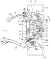
図3は、この発明の実施の形態の第2の参考例による車輪支持装置およびそれによって支持される電動輪の概略断面図である。また、図4は、図3に示すA方向から見たインホイールモータIWMおよび車輪支持装置の平面図である。
[ Reference Example 2]
FIG. 3 is a schematic cross-sectional view of a wheel support device according to a second reference example of the embodiment of the present invention and an electric wheel supported thereby. FIG. 4 is a plan view of the in-wheel motor IWM and the wheel support device viewed from the direction A shown in FIG.

図3を参照して、電動輪100は、車輪支持装置200Aによって支持される。   Referring to FIG. 3, electric wheel 100 is supported by wheel support device 200A.

図3および図4を参照して、車輪支持装置200Aは、車輪支持装置200のトルクロッド190および部材194をそれぞれトルクロッド290および部材294に代えたものであり、その他は、車輪支持装置200と同じである。   Referring to FIGS. 3 and 4, wheel support device 200 </ b> A is obtained by replacing torque rod 190 and member 194 of wheel support device 200 with torque rod 290 and member 294, respectively. The same.

トルクロッド290は、直線部291と、湾曲部292と、端部293とからなる。直線部291は、その一方端がボールジョイント160に連結され、他方端が湾曲部292に連結される。湾曲部292は、部材294に設けられた孔2941に挿入され、部材294を貫通する。そして、湾曲部292は、一方端が直線部291に連結され、他方端が端部293に連結される。湾曲部292は、等速ジョイント30の中心Oから半径Rの軌道OBTに沿って湾曲されている。端部293は、部材294の孔2941の直径よりも大きい直径を有する。   The torque rod 290 includes a straight portion 291, a curved portion 292, and an end portion 293. The straight portion 291 has one end connected to the ball joint 160 and the other end connected to the curved portion 292. The bending portion 292 is inserted into a hole 2941 provided in the member 294 and penetrates the member 294. The curved portion 292 has one end connected to the straight portion 291 and the other end connected to the end portion 293. The curved portion 292 is curved along the track OBT having a radius R from the center O of the constant velocity joint 30. End 293 has a diameter that is greater than the diameter of hole 2941 in member 294.

直線部291は、ボールジョイント160との連結部から車体に向かう方向(紙面奥から手前に向かう方向)に、車体の進行方向DR2に対して斜め方向に配置される。   The straight line portion 291 is disposed obliquely with respect to the traveling direction DR2 of the vehicle body in a direction from the connecting portion with the ball joint 160 toward the vehicle body (a direction from the back of the sheet to the front).

部材294は、ケース60の端面60Aに固定される。そして、部材294は、インホイールモータIWMが車体の上下方向DR1に振動することに伴って湾曲部292に沿って車体の上下方向DR1に振動可能である。   The member 294 is fixed to the end surface 60 </ b> A of the case 60. The member 294 can vibrate in the vertical direction DR1 of the vehicle body along the curved portion 292 as the in-wheel motor IWM vibrates in the vertical direction DR1 of the vehicle body.

端部293は、インホイールモータIWMがロアアーム220側に移動したことに伴って部材294に当接し、部材294がロアアーム220側へ一定範囲を超えて移動するのを抑止する。つまり、端部293は、インホイールモータIWMがロアアーム220側へ一定範囲を超えて移動するのを抑止する。これによって、インホイールモータIWMのロアアーム220への衝突が回避される。   The end portion 293 abuts on the member 294 as the in-wheel motor IWM moves to the lower arm 220 side, and suppresses the member 294 from moving beyond a certain range to the lower arm 220 side. That is, the end portion 293 inhibits the in-wheel motor IWM from moving beyond the certain range to the lower arm 220 side. Thereby, the collision of the in-wheel motor IWM with the lower arm 220 is avoided.

トルクロッド290および部材294は、車輪支持装置200のトルクロッド190および部材194と同じ機能を果たし、電動輪100の回転方向DR3への回転によって生じるインホイールモータIWMの回転方向DR4への回転を抑制する。また、トルクロッド290および部材294は、電動輪100の上下方向DR1への振動に伴うインホイールモータIWMの上下方向DR1への振動を軌道OBT上に規制するとともに、インホイールモータIWMがロアアーム220に衝突するのを防止する。   Torque rod 290 and member 294 perform the same function as torque rod 190 and member 194 of wheel support device 200 and suppress rotation of in-wheel motor IWM caused by rotation of electric wheel 100 in rotation direction DR3. To do. Further, the torque rod 290 and the member 294 regulate the vibration in the vertical direction DR1 of the in-wheel motor IWM on the track OBT accompanying the vibration in the vertical direction DR1 of the electric wheel 100, and the in-wheel motor IWM is connected to the lower arm 220. Prevent collisions.

そして、トルクロッド290および部材294は、「回転抑制部材」を構成し、回転抑制部材は、一方端がボールジョイント160に連結され、他方端が1つの連結部(部材294)によってインホイールモータIWMに連結される。   The torque rod 290 and the member 294 constitute a “rotation suppressing member”. The rotation suppressing member has one end connected to the ball joint 160 and the other end connected to the in-wheel motor IWM by one connecting portion (member 294). Connected to

このように、参考例2による回転抑制部材は、1つのトルクロッド290および1つの部材294によって構成されることを特徴とする。 As described above, the rotation suppressing member according to the reference example 2 includes one torque rod 290 and one member 294.

なお、上記においては、トルクロッド290は、アッパーアーム210側に配置されたボールジョイント160に連結されると説明したが、この発明においては、これに限らず、トルクロッド290は、ロアアーム220側に配置されたボールジョイント170に連結されてもよい。また、この発明においては、トルクロッドは、アッパーアーム210側に配置されたボールジョイント160およびロアアーム220側に配置されたボールジョイント170の両方に連結されていてもよい。つまり、この発明においては、トルクロッドは、アッパーアーム210側に配置されたボールジョイント160およびロアアーム220側に配置されたボールジョイント170の少なくとも一方に連結されていればよい。   In the above description, the torque rod 290 has been described as being connected to the ball joint 160 disposed on the upper arm 210 side. However, the present invention is not limited to this, and the torque rod 290 is disposed on the lower arm 220 side. You may connect with the ball joint 170 arrange | positioned. In the present invention, the torque rod may be connected to both the ball joint 160 disposed on the upper arm 210 side and the ball joint 170 disposed on the lower arm 220 side. In other words, in the present invention, the torque rod only needs to be connected to at least one of the ball joint 160 disposed on the upper arm 210 side and the ball joint 170 disposed on the lower arm 220 side.

その他は、参考例1と同じである。 Others are the same as Reference Example 1 .

上述した参考例1,2において、回転抑制部材(トルクロッド190および部材194またはトルクロッド290および部材294)は、2つの連結部(194A,194B)または1つの連結部(294)によってインホイールモータIWMに連結されると説明したが、この発明においては、回転抑制部材は、少なくとも1つの連結部によってインホイールモータIWMに連結されていればよい。 In the reference examples 1 and 2 described above, the rotation suppressing member (torque rod 190 and member 194 or torque rod 290 and member 294) is an in-wheel motor by two connecting portions (194A, 194B) or one connecting portion (294). Although described as being connected to the IWM, in the present invention, the rotation suppressing member only needs to be connected to the in-wheel motor IWM by at least one connecting portion.

[実施の形態]
図5は、この発明の実施の形態による車輪支持装置およびそれによって支持される電動輪の概略断面図である。また、図6は、図5に示すA方向から見た電動輪および車輪支持装置の平面図である。
[Form state of implementation]
Figure 5 is a schematic cross-sectional view of a motor-driven wheel supported by the wheel supporting apparatus and its by form state of the present invention. FIG. 6 is a plan view of the motor-driven wheel and the wheel support device viewed from the direction A shown in FIG.

図5を参照して、電動輪100は、ホイールディスク10と、ホイールハブ20と、等速ジョイント30と、ブレーキロータ40と、ブレーキキャリパ50と、インホイールモータIWMと、タイヤ250とを備える。   Referring to FIG. 5, the electric wheel 100 includes a wheel disc 10, a wheel hub 20, a constant velocity joint 30, a brake rotor 40, a brake caliper 50, an in-wheel motor IWM, and a tire 250.

インホイールモータIWMは、ケース60と、シャフト110とを有する。また、インホイールモータIWMは、モータと、プラネタリギヤと、オイルポンプと、オイル通路とを含む。モータ、プラネタリギヤ、オイルポンプおよびオイル通路は、ケース60に収納されているため、図5においては図示されていない。   The in-wheel motor IWM has a case 60 and a shaft 110. In-wheel motor IWM includes a motor, a planetary gear, an oil pump, and an oil passage. Since the motor, the planetary gear, the oil pump, and the oil passage are housed in the case 60, they are not shown in FIG.

図5および図6を参照して、電動輪100は、車輪支持装置200Bによって支持される。車輪支持装置200Bは、ダイナミックダンパマス機構300と、ボールジョイント160,170と、ナックル280と、トルクロッド390と、アッパーアーム210と、ロアアーム220と、ショックアブソーバ(図示せず)とを含む。   With reference to FIGS. 5 and 6, motor-driven wheel 100 is supported by wheel support device 200 </ b> B. Wheel support device 200B includes a dynamic damper mass mechanism 300, ball joints 160 and 170, a knuckle 280, a torque rod 390, an upper arm 210, a lower arm 220, and a shock absorber (not shown).

ナックル280(280a)は、一方端がボールジョイント160に連結され、他方端がハブベアリング11,12を介してホイールハブ20に連結される。ナックル280(280b)は、一方端が図示しないプレートにボルトにより固定され、他方端がハブベアリング11,12を介してホイールハブ20に連結される。なお、図示しないプレートは、ボールジョイント170に連結される。これによって、ナックル280は、ホイールハブ20およびホイールディスク10を回転可能に支持する。   The knuckle 280 (280a) has one end connected to the ball joint 160 and the other end connected to the wheel hub 20 via the hub bearings 11 and 12. The knuckle 280 (280b) has one end fixed to a plate (not shown) with a bolt and the other end connected to the wheel hub 20 via hub bearings 11 and 12. A plate (not shown) is connected to the ball joint 170. Thereby, the knuckle 280 supports the wheel hub 20 and the wheel disc 10 rotatably.

トルクロッド390(390a)は、一方端がインホイールモータIWMのケース60に連結され、他方端がナックル280(280a)に連結される。トルクロッド390(390b)は、一方端がケース60に連結され、他方端がナックル280(280b)に連結される。   Torque rod 390 (390a) has one end connected to case 60 of in-wheel motor IWM and the other end connected to knuckle 280 (280a). Torque rod 390 (390b) has one end connected to case 60 and the other end connected to knuckle 280 (280b).

図6に示すように、トルクロッド390は、車両の進行方向DR2に対して、インホイールモータIWMを挟んで、ブレーキキャリパ50の反対側に配置される。そして、トルクロッド390aとトルクロッド390bとは、車両の上下方向DR1に沿って所定の距離を隔てて配置される。   As shown in FIG. 6, the torque rod 390 is disposed on the opposite side of the brake caliper 50 with the in-wheel motor IWM interposed in the traveling direction DR2 of the vehicle. Torque rod 390a and torque rod 390b are arranged at a predetermined distance along the vertical direction DR1 of the vehicle.

電動輪100は、インホイールモータIWMから出力されるトルクによって回転されるので、電動輪100の回転に伴って、電動輪100の回転方向DR3と反対の回転方向DR4に回転しようとする回転反力がインホイールモータIWMに生じ、インホイールモータIWMは、回転方向DR4に回転する。   Since the electric wheel 100 is rotated by the torque output from the in-wheel motor IWM, as the electric wheel 100 rotates, the rotational reaction force that tries to rotate in the rotation direction DR4 opposite to the rotation direction DR3 of the electric wheel 100. Occurs in the in-wheel motor IWM, and the in-wheel motor IWM rotates in the rotation direction DR4.

そうすると、トルクロッド390a,390bは、一方端がインホイールモータIWMのケース60に固定されており、他方端がナックル280a,280bにそれぞれ連結されているので、回転方向DR4へのインホイールモータIWMの回転を抑制する。すなわち、トルクロッド390は、回転抑制部材を構成し、インホイールモータIWMの回転方向DR4への回転による剪断力がナックル280にかかるのが抑制される。   Then, torque rods 390a and 390b have one end fixed to case 60 of in-wheel motor IWM and the other end connected to knuckles 280a and 280b, respectively, so that in-wheel motor IWM in rotational direction DR4 Suppresses rotation. That is, torque rod 390 constitutes a rotation suppression member, and it is suppressed that shearing force due to rotation of in-wheel motor IWM in rotation direction DR4 is applied to knuckle 280.

ダイナミックマスダンパ機構300は、車両の上下方向に設けられる1対の弾性部材であるスプリング302,304から構成される。ダイナミックマスダンパ機構300の中央部306は、インホイールモータIWMのケース60の外周側面に取り付けられる。   The dynamic mass damper mechanism 300 includes springs 302 and 304 that are a pair of elastic members provided in the vertical direction of the vehicle. A central portion 306 of the dynamic mass damper mechanism 300 is attached to the outer peripheral side surface of the case 60 of the in-wheel motor IWM.

ここで、本実施の形態において、ダイナミックマスダンパ機構300は、図5に示すように、車体の進行方向(紙面垂直方向に相当)から見て、中央部306がインホイールモータIWMの重心線L1上に位置するように取り付けられることを特徴とする。なお、重心線L1とは、インホイールモータIWMの重心を通り、かつインホイールモータIWMの振動方向(車両の上下方向DR1に相当)に平行な直線である。さらに、ダイナミックマスダンパ機構300の中央部306は、インホイールモータIWMの回転軸と同じ高さになる位置に取り付けられる。   Here, in the present embodiment, as shown in FIG. 5, the dynamic mass damper mechanism 300 has a central portion 306 whose center line 306 is the center of gravity line L1 of the in-wheel motor IWM as viewed from the traveling direction of the vehicle body (corresponding to the direction perpendicular to the paper surface). It is attached so that it may be located on. The center of gravity line L1 is a straight line that passes through the center of gravity of the in-wheel motor IWM and is parallel to the vibration direction of the in-wheel motor IWM (corresponding to the vertical direction DR1 of the vehicle). Further, the central portion 306 of the dynamic mass damper mechanism 300 is attached at a position that is the same height as the rotation shaft of the in-wheel motor IWM.

そして、ダイナミックマスダンパ機構300の上部310は、ナックル280aに接続される。上部310と中央部306とは、スプリング302を介して接続される。ダイナミックマスダンパ機構300の下部312は、ナックル280bに接続される。中央部306と下部312とは、スプリング304を介して接続される。   The upper portion 310 of the dynamic mass damper mechanism 300 is connected to the knuckle 280a. The upper part 310 and the central part 306 are connected via a spring 302. The lower part 312 of the dynamic mass damper mechanism 300 is connected to the knuckle 280b. The central part 306 and the lower part 312 are connected via a spring 304.

また、ダイナミックマスダンパ機構300の上部310と下部312との間には、中央部306を貫通してアブソーバ314が配される。アブソーバ314は、一方端が中央部306に固定されるシャフト316を含む。シャフト316は、スプリング304の伸縮に応じて上下方向に振動する。アブソーバ314は、シャフト316の上下方向の振動を減衰させる。中央部306を貫通するシャフト316は、ブッシュ308により車両の進行方向DR2の位置が制限される。また、アブソーバ314の下端は、ブッシュ326により車両の進行方向DR2の位置が制限される。   An absorber 314 is disposed between the upper part 310 and the lower part 312 of the dynamic mass damper mechanism 300 so as to penetrate the central part 306. The absorber 314 includes a shaft 316 whose one end is fixed to the central portion 306. The shaft 316 vibrates in the vertical direction according to the expansion and contraction of the spring 304. The absorber 314 attenuates the vertical vibration of the shaft 316. The position of the shaft 316 passing through the central portion 306 is restricted by the bush 308 in the vehicle traveling direction DR2. Further, the position of the lower end of the absorber 314 in the traveling direction DR2 of the vehicle is restricted by the bush 326.

さらに、本実施の形態において、ダイナミックマスダンパ機構300は、図6に示すように、車両の進行方向DR2に沿って、インホイールモータIWMを挟んでブレーキキャリパ50と反対側に配置されることを特徴とする。すなわち、本実施の形態において、ダイナミックマスダンパ機構300およびトルクロッド390と、ブレーキキャリパ50とは、車両の進行方向DR2に沿って、インホイールモータIWMの両側にそれぞれ配置される。   Further, in the present embodiment, as shown in FIG. 6, the dynamic mass damper mechanism 300 is disposed on the opposite side of the brake caliper 50 across the in-wheel motor IWM along the traveling direction DR2 of the vehicle. Features. That is, in the present embodiment, dynamic mass damper mechanism 300, torque rod 390, and brake caliper 50 are arranged on both sides of in-wheel motor IWM, respectively, along vehicle traveling direction DR2.

その結果、トルクロッド390およびダイナミックマスダンパ機構300の各々は、回転支持部材であるナックル280の近傍に配設される。これにより、ナックル280とトルクロッド390およびダイナミックマスダンパ機構300との間の相対的な距離が縮められ、ナックル280にかかる曲げモーメントが低減されることから、ナックル280の耐久性の向上できる。すなわち、車輪支持装置200Bの耐久性を向上できる。   As a result, each of the torque rod 390 and the dynamic mass damper mechanism 300 is disposed in the vicinity of the knuckle 280 that is a rotation support member. Thereby, the relative distance between the knuckle 280, the torque rod 390, and the dynamic mass damper mechanism 300 is shortened, and the bending moment applied to the knuckle 280 is reduced, so that the durability of the knuckle 280 can be improved. That is, the durability of the wheel support device 200B can be improved.

さらに、ナックル280がインホイールモータIWMを支持するのに必要な強度は、従来の車輪支持装置に対して相対的に低いもので十分であることから、ナックル280の小型軽量化を図ることができる。   Furthermore, since the strength required for the knuckle 280 to support the in-wheel motor IWM is relatively low compared to the conventional wheel support device, the knuckle 280 can be reduced in size and weight. .

さらに、車輪支持装置200Bは、図6に示すように、トルクロッド390およびダイナミックマスダンパ機構300がインホールモータIWMの重心線から車体の進行方向DR2にオフセットして配置されることから、車体の上下方向DR1に沿って、インホイールモータIWMの上方および下方にトルクロッド190およびモータマウント140,150が配置される図1の電動輪100に対して、インホイールモータIWMの車両の上下方向DR1により広いスペースを確保することができる。これにより、車輪支持装置200Bの搭載性が向上する。   Furthermore, as shown in FIG. 6, the wheel support device 200 </ b> B is configured such that the torque rod 390 and the dynamic mass damper mechanism 300 are arranged offset from the center of gravity line of the in-hole motor IWM in the traveling direction DR <b> 2 of the vehicle body. With respect to the electric wheel 100 of FIG. 1 in which the torque rod 190 and the motor mounts 140 and 150 are arranged above and below the in-wheel motor IWM along the vertical direction DR1, the vertical direction DR1 of the vehicle of the in-wheel motor IWM A wide space can be secured. Thereby, the mountability of the wheel support device 200B is improved.

また、ダイナミックマスダンパ機構300をインホイールモータIWMの一方向側にのみ配置することによって、インホイールIWMの他方側(ブレーキキャリパ50側)に有効なスペースを確保することができる。   Further, by disposing the dynamic mass damper mechanism 300 only on one side of the in-wheel motor IWM, an effective space can be secured on the other side (brake caliper 50 side) of the in-wheel IWM.

なお、本実施の形態において、ダイナミックマスダンパ機構300は、インホイールモータIWMの車体の進行方向DR2の一方向側にのみに配置されるが、トルクロッド390が、インホイールモータIWMの回転方向DR4への回転を抑制し、インホイールモータIWMの振動方向を車両の上下方向DR1に規制することから、所望のダンパー性能を実現することができる。   In the present embodiment, the dynamic mass damper mechanism 300 is disposed only on one side of the in-wheel motor IWM in the traveling direction DR2 of the vehicle body, but the torque rod 390 is in the rotational direction DR4 of the in-wheel motor IWM. Since the rotation direction of the in-wheel motor IWM is restricted to the vertical direction DR1 of the vehicle, a desired damper performance can be realized.

再び図5を参照して、アッパーアーム210およびロアアーム220は、車体の上下方向DR1に配置される。アッパーアーム210は、一方端がボールジョイント160に連結され、他方端が車体の上下方向DR1に回動可能に車体に固定される。ロアアーム220は、一方端がボールジョイント170に連結され、他方端が車体の上下方向DR1に回動可能に車体に固定される。また、ロアアーム220は、図示しないショックアブソーバを介して車体に連結される。これにより、電動輪100は、車体に懸架される。   Referring to FIG. 5 again, upper arm 210 and lower arm 220 are arranged in the vertical direction DR1 of the vehicle body. The upper arm 210 has one end connected to the ball joint 160 and the other end fixed to the vehicle body so as to be rotatable in the vertical direction DR1 of the vehicle body. The lower arm 220 has one end connected to the ball joint 170 and the other end fixed to the vehicle body so as to be rotatable in the vertical direction DR1 of the vehicle body. The lower arm 220 is connected to the vehicle body via a shock absorber (not shown). As a result, the electric wheel 100 is suspended from the vehicle body.

このように、アッパーアーム210およびロアアーム220は、車体の上下方向DR1からそれぞれボールジョイント160,170を介してナックル280a,280bにそれぞれ連結される。   Thus, the upper arm 210 and the lower arm 220 are connected to the knuckles 280a and 280b via the ball joints 160 and 170, respectively, from the vertical direction DR1 of the vehicle body.

そして、ナックル280a,280bは、図示しないステアリングタイロッドの一方端に連結される。ステアリングタイロッドは、車体のステアリング(ハンドル)からの回転力に応じて、車両の進行方向に対して右方向または左方向に電動輪100を回動する。   Knuckles 280a and 280b are connected to one end of a steering tie rod (not shown). The steering tie rod rotates the electric wheel 100 in the right direction or the left direction with respect to the traveling direction of the vehicle in accordance with the rotational force from the steering (handle) of the vehicle body.

アッパーアーム210およびロアアーム220は、車体の上下方向DR1に回動自在に車体に固定され、ロアアーム220は、ショックアブソーバ230を介して車体に連結されるので、アッパーアーム210、ロアアーム220およびショックアブソーバ230は、サスペンションとして機能する。そして、アッパーアーム210およびロアアーム220は、「サスペンションアーム」を構成する。   Since the upper arm 210 and the lower arm 220 are fixed to the vehicle body so as to be rotatable in the vertical direction DR1 of the vehicle body, and the lower arm 220 is connected to the vehicle body via the shock absorber 230, the upper arm 210, the lower arm 220, and the shock absorber 230 Functions as a suspension. The upper arm 210 and the lower arm 220 constitute a “suspension arm”.

ダイナミックマスダンパ機構300は、中央部306において、インホイールモータIWMのケース60に固定される。また、ダイナミックマスダンパ機構300は、ナックル280に連結される。そして、ボールジョイント160,170によって、ナックル280とサスペンションアーム(アッパーアーム210およびロアアーム220)とを連結することにより、車輪支持装置200Bは、電動輪100を車体に支持する。   The dynamic mass damper mechanism 300 is fixed to the case 60 of the in-wheel motor IWM at the central portion 306. Further, the dynamic mass damper mechanism 300 is connected to the knuckle 280. Then, by connecting the knuckle 280 and the suspension arm (the upper arm 210 and the lower arm 220) by the ball joints 160 and 170, the wheel support device 200B supports the electric wheel 100 on the vehicle body.

すなわち、車輪支持装置200Bは、アッパーアーム210、ロアアーム220およびナックル280によって、ホイールディスク10およびホイールハブ20を回転可能に支持するとともに、アッパーアーム210、ロアアーム220およびダイナミックマスダンパ機構300によって、インホイールモータIWMを車両の上下方向DR1に振動可能に支持する。   That is, the wheel support device 200B rotatably supports the wheel disc 10 and the wheel hub 20 by the upper arm 210, the lower arm 220, and the knuckle 280, and the in-wheel by the upper arm 210, the lower arm 220, and the dynamic mass damper mechanism 300. The motor IWM is supported so as to be able to vibrate in the vertical direction DR1 of the vehicle.

また、車両の走行中に、電動輪100が回転方向DR3に回転すると、インホイールモータIWMは、回転方向DR4に回転する。そうすると、トルクロッド390は、電動輪100の回転によって生じるインホイールモータIWMの回転を抑制する。   Further, when the electric wheel 100 rotates in the rotation direction DR3 while the vehicle is traveling, the in-wheel motor IWM rotates in the rotation direction DR4. Then, torque rod 390 suppresses rotation of in-wheel motor IWM caused by rotation of electric wheel 100.

以上の構成において、車両の走行中に、電動輪100が路面状態等に応じて車体の上下方向DR1に振動を受けると、ダンパーマスとなるインホイールモータIWMによってダイナミックマスダンパ機構300のスプリング302,304は、車体の上下方向DR1に伸縮する。スプリング302,304は、電動輪100が受けた振動と位相のずれたインホイールモータIWMの上下方向DR1への振動を発生させる。つまり、ダイナミックマスダンパ機構300は、電動輪100の振動をインホイールモータIWMの振動に変換する。このとき、電動輪100の振動とインホイールモータIWMの振動とは互いに位相がずれているため、電動輪100が受けた振動は、インホイールモータIWMに生じた振動によって相殺される。すなわち、ダイナミックマスダンパ機構300は、電動輪100の振動とインホイールモータIWMの振動とを互いに減衰する。そうすると、電動輪100の振動は、アッパーアーム210およびロアアーム220を介して車体に伝達されにくくなる。   In the above configuration, when the motor-driven wheel 100 is vibrated in the vertical direction DR1 of the vehicle body according to the road surface condition or the like while the vehicle is running, the springs 302 of the dynamic mass damper mechanism 300 are driven by the in-wheel motor IWM serving as a damper mass. 304 expands and contracts in the vertical direction DR1 of the vehicle body. The springs 302 and 304 generate vibrations in the vertical direction DR1 of the in-wheel motor IWM that is out of phase with the vibrations received by the electric wheels 100. That is, the dynamic mass damper mechanism 300 converts the vibration of the electric wheel 100 into the vibration of the in-wheel motor IWM. At this time, since the vibration of the electric wheel 100 and the vibration of the in-wheel motor IWM are out of phase with each other, the vibration received by the electric wheel 100 is canceled by the vibration generated in the in-wheel motor IWM. That is, the dynamic mass damper mechanism 300 attenuates the vibration of the electric wheel 100 and the vibration of the in-wheel motor IWM. If it does so, it will become difficult to transmit the vibration of the motor-driven wheel 100 to the vehicle body via the upper arm 210 and the lower arm 220.

インホイールモータIWMは、等速ジョイント30を介して上下に振動する。具体的には、インホイールモータIWMは、等速ジョイント30を回転中心として、車体の上下方向DR1に円弧を描くように振動する。このとき、インホイールモータIWMの車体の進行方向DR2の振動は、ダイナミックマスダンパ機構300の中央部306および下部312にそれぞれ設けられるブッシュ308,326により吸収される。   The in-wheel motor IWM vibrates up and down via the constant velocity joint 30. Specifically, the in-wheel motor IWM vibrates so as to draw an arc in the vertical direction DR1 of the vehicle body with the constant velocity joint 30 as the rotation center. At this time, the vibration in the traveling direction DR2 of the vehicle body of the in-wheel motor IWM is absorbed by the bushes 308 and 326 provided in the central portion 306 and the lower portion 312 of the dynamic mass damper mechanism 300, respectively.

さらに、ダイナミックマスダンパ機構300の中央部306は、先述のように、インホイールモータIWMの重心線L1上でインホイールモータIWMに固定される。これによれば、スプリング302,304の伸縮によって生じるインホイールモータIWMの振動の安定度を高めることができる。より詳細には、インホイールモータIWMは、電動輪100の振動に応じて、等速ジョイント30を回転中心として、車両の上下方向DR1に円弧を描くように振動する。このとき、ダイナミックマスダンパ機構300は、ダンパーマスとなるインホイールモータIWMの重心を常に支持することから、インホイールモータIWMの振動を安定させるとともに、この振動をアブソーバ314によって効率良く減衰させることができる。その結果、等速ジョイント30にかかる荷重負荷が低減され、等速ジョイント30の耐久性を向上できる。すなわち、車輪支持装置200Bの耐久性を向上できる。また、等速ジョイント30を小型軽量化できることから、車輪支持装置200Bの小型軽量化にも有効である。   Further, the central portion 306 of the dynamic mass damper mechanism 300 is fixed to the in-wheel motor IWM on the center of gravity line L1 of the in-wheel motor IWM as described above. According to this, the stability of the vibration of the in-wheel motor IWM caused by the expansion and contraction of the springs 302 and 304 can be increased. More specifically, the in-wheel motor IWM vibrates so as to draw an arc in the vertical direction DR1 of the vehicle with the constant velocity joint 30 as the rotation center in accordance with the vibration of the electric wheel 100. At this time, the dynamic mass damper mechanism 300 always supports the center of gravity of the in-wheel motor IWM serving as the damper mass, so that the vibration of the in-wheel motor IWM can be stabilized and the vibration can be efficiently damped by the absorber 314. it can. As a result, the load applied to the constant velocity joint 30 is reduced, and the durability of the constant velocity joint 30 can be improved. That is, the durability of the wheel support device 200B can be improved. Moreover, since the constant velocity joint 30 can be reduced in size and weight, it is effective for reducing the size and weight of the wheel support device 200B.

このようにして、タイヤ250からのバネ下入力が緩和される。すなわち、電動輪100に振動が生じると、サスペンションに設けられるショックアブソーバによって吸収し切れない振動がダイナミックマスダンパ機構300によって吸収される。その結果、車両の乗り心地が向上する。   In this way, unsprung input from the tire 250 is alleviated. That is, when vibration occurs in the electric wheel 100, vibration that cannot be absorbed by the shock absorber provided in the suspension is absorbed by the dynamic mass damper mechanism 300. As a result, the ride comfort of the vehicle is improved.

なお、本実施の形態において、ダイナミックマスダンパ機構300は、互いに独立したスプリング302,304から構成される。そして、スプリング302,304は、それぞれ、車体の上下方向DR1のストローク範囲中において撓みを持つ状態となっている。   In the present embodiment, the dynamic mass damper mechanism 300 includes springs 302 and 304 that are independent of each other. The springs 302 and 304 are in a state of being bent in the stroke range in the vertical direction DR1 of the vehicle body.

このような構成とすることにより、中央部306、上部310および下部312の少なくとも1つにおいて、スプリング302,304のバネ座面の位置を容易に調整することができる。例えば、図5のように、上部310をシム3100とスナップリング3102とを組み合わせて構成すれば、これらの車体の上下方向DR1の高さを変更することによって、容易にスプリング302のバネ座面の位置を調整することができる。あるいは、上部310を、図7に示すように、2つのナット3104,3106(またはボルト)を連結して構成すれば、各ナットの車体の上下方向DR1の高さを変更することによって、容易にバネ座面の位置を調整することができる。そして、図5および図7のいずれかの構成を、中央部306または下部312にも適用することにより、インホイールモータIWMの中立位置の調整およびスプリング302,304のストローク調整を容易に行なうことができ、設計変更に伴なうコストを大幅に低減することができる。   With such a configuration, the positions of the spring seat surfaces of the springs 302 and 304 can be easily adjusted in at least one of the central portion 306, the upper portion 310, and the lower portion 312. For example, as shown in FIG. 5, if the upper part 310 is configured by combining a shim 3100 and a snap ring 3102, the height of the spring seat surface of the spring 302 can be easily changed by changing the height in the vertical direction DR 1 of these vehicle bodies. The position can be adjusted. Alternatively, if the upper portion 310 is configured by connecting two nuts 3104 and 3106 (or bolts) as shown in FIG. 7, it is easy to change the height of each nut in the vertical direction DR1 of the vehicle body. The position of the spring seat surface can be adjusted. 5 and 7 are also applied to the central portion 306 or the lower portion 312 so that the neutral position of the in-wheel motor IWM and the strokes of the springs 302 and 304 can be easily adjusted. This can significantly reduce the cost associated with the design change.

また、この発明において、スプリング302,304は互いに独立し、予め自然長から圧縮された状態で組み付けられていることから、単一のスプリングでダイナミックマスダンパ機構300を構成するのに対して、スプリングのバネ定数は略半分となる。その結果、スプリング302,304の素線径を細くして内径を大きくとることができ、スプリング302,304の内周側にアブソーバ314を配置することができる。   Further, in the present invention, the springs 302 and 304 are independent of each other and assembled in advance in a state compressed from a natural length, so that the dynamic mass damper mechanism 300 is configured by a single spring, whereas the spring The spring constant of is approximately half. As a result, the wire diameters of the springs 302 and 304 can be reduced to increase the inner diameter, and the absorber 314 can be disposed on the inner peripheral side of the springs 302 and 304.

なお、ホイールディスク10およびホイールハブ20は、「ホイール」を構成する。   The wheel disc 10 and the wheel hub 20 constitute a “wheel”.

また、ダイナミックマスダンパ機構300は、「弾性部材」を構成し、スプリング302,304は、「1対の弾性部材」を構成する。そして、アブソーバ314は、「振動減衰機構」を構成する。   The dynamic mass damper mechanism 300 constitutes an “elastic member”, and the springs 302 and 304 constitute “a pair of elastic members”. The absorber 314 constitutes a “vibration damping mechanism”.

さらに、トルクロッド390は、「回転抑制部材」を構成する。   Further, the torque rod 390 constitutes a “rotation suppressing member”.

さらに、ナックル280は、電動輪100のホイール(ホイールディスク10およびホイールハブ20)を回転可能に支持する「回転支持部材」を構成する。   Further, the knuckle 280 constitutes a “rotation support member” that rotatably supports the wheel (wheel disc 10 and wheel hub 20) of the electric wheel 100.

参考例3
図8は、この発明の実施の形態の第3の参考例による車輪支持装置およびそれによって支持されるインホイールモータIWMの概略断面図である。
[ Reference Example 3 ]
FIG. 8 is a schematic cross-sectional view of a wheel support device according to a third reference example of the embodiment of the present invention and an in-wheel motor IWM supported by the wheel support device.

図8を参照して、車輪支持装置200Cは、車輪支持装置200Bのダイナミックマスダンパ機構300を、2個のダイナミックマスダンパ機構300,300Aに代えたものである。なお、ダイナミックマスダンパ機構300Aは、図5および図6で示したダイナミックマスダンパ機構300と同一の構造からなる。   Referring to FIG. 8, wheel support device 200C is obtained by replacing dynamic mass damper mechanism 300 of wheel support device 200B with two dynamic mass damper mechanisms 300, 300A. The dynamic mass damper mechanism 300A has the same structure as the dynamic mass damper mechanism 300 shown in FIGS.

より詳細には、ダイナミックマスダンパ機構300,300Aは、車両の進行方向DR1に沿ってインホイールモータIWMの両側に配設される。   More specifically, the dynamic mass damper mechanisms 300 and 300A are disposed on both sides of the in-wheel motor IWM along the traveling direction DR1 of the vehicle.

ダイナミックマスダンパ機構300,300Aは、図示は省略するが、いずれもインホイールモータIWMの重心線L1上に中央部306が位置するように、インホイールモータIWMの外周側面に取り付けられる。このとき、ダイナミックマスダンパ機構300,300Aにおいて、アブソーバ314は、中央部306に設けたブッシュ308によって、インホイールモータIWMの回転方向DR4への回転を許容するように固定される。さらに、アブソーバ314は、下部312に設けたブッシュ326によって、インホイールモータIWMの回転方向DR4への回転を許容するように固定される。   Although not shown, the dynamic mass damper mechanisms 300 and 300A are attached to the outer peripheral side surface of the in-wheel motor IWM so that the central portion 306 is positioned on the center of gravity line L1 of the in-wheel motor IWM. At this time, in the dynamic mass damper mechanisms 300 and 300A, the absorber 314 is fixed by the bush 308 provided in the central portion 306 so as to allow the rotation of the in-wheel motor IWM in the rotation direction DR4. Further, the absorber 314 is fixed by a bush 326 provided in the lower portion 312 so as to allow the in-wheel motor IWM to rotate in the rotational direction DR4.

トルクロッド390(390a,390b)は、上述したように、インホイールモータIWMの回転方向DR4への回転を抑制し、インホイールモータIWMの振動方向を車両の上下方向DR1に規制する。   As described above, the torque rod 390 (390a, 390b) suppresses the rotation of the in-wheel motor IWM in the rotation direction DR4 and restricts the vibration direction of the in-wheel motor IWM to the vertical direction DR1 of the vehicle.

このような構成とすることにより、インホイールモータIWMに生じた車両の上下方向DR1の振動は、インホイールモータIWMの両側に位置するダイナミックマスダンパ機構300,300Aに均等に伝達されることになる。すなわち、ダイナミックマスダンパ機構300,300Aの各々が、インホイールモータIWMの振動を吸収するように働くことから、図5の車輪支持装置200Bに対して、部品点数が増えるものの、電動輪100に生じた振動をより効率良く吸収することができ、乗り心地がさらに向上する。   With this configuration, the vibration in the vertical direction DR1 of the vehicle generated in the in-wheel motor IWM is evenly transmitted to the dynamic mass damper mechanisms 300 and 300A located on both sides of the in-wheel motor IWM. . That is, since each of the dynamic mass damper mechanisms 300 and 300A works to absorb the vibration of the in-wheel motor IWM, the number of parts increases with respect to the wheel support device 200B of FIG. Can absorb the vibrations more efficiently and further improve the ride comfort.

なお、本参考例において、インホイールIWMのシャフト110とホイールディスク10とを連結する等速ジョイント30(図示せず)は、インホイールモータIWMのシャフト110を回転軸方向に固定するタイプもしくは、シャフト110を回転軸方向にスライド可能なタイプのいずれをも適用することができる。 In this reference example, the constant velocity joint 30 (not shown) that connects the shaft 110 of the in-wheel IWM and the wheel disk 10 is a type that fixes the shaft 110 of the in-wheel motor IWM in the rotation axis direction, or a shaft Any type that can slide 110 in the direction of the rotation axis can be applied.

参考例4
図9は、この発明の実施の形態の第4の参考例による車輪支持装置およびそれによって支持されるインホイールモータIWMの概略断面図である。
[ Reference Example 4 ]
FIG. 9 is a schematic cross-sectional view of a wheel support device and an in-wheel motor IWM supported by the wheel support device according to the fourth embodiment of the present invention.

図9を参照して、車輪支持装置200Dは、車輪支持装置200Cの一対のダイナミックマスダンパ機構300,300Aを、一対のダイナミックマスダンパ機構310,310Aに代えたものである。また、車輪支持装置200Dは、車輪支持装置200Cからトルクロッド390を削除したものである。   Referring to FIG. 9, wheel support device 200D is obtained by replacing the pair of dynamic mass damper mechanisms 300, 300A of wheel support device 200C with a pair of dynamic mass damper mechanisms 310, 310A. Further, the wheel support device 200D is obtained by deleting the torque rod 390 from the wheel support device 200C.

ダイナミックマスダンパ機構310,310Aは、車両の進行方向DR2に沿ってインホイールモータIWMの両側に配設される。また、ダイナミックマスダンパ機構310,310Aは、それぞれインホイールモータIWMの重心線L1上に中央部306が位置するように、インホイールモータIWMの外周側面に取り付けられる。   The dynamic mass damper mechanisms 310 and 310A are disposed on both sides of the in-wheel motor IWM along the traveling direction DR2 of the vehicle. The dynamic mass damper mechanisms 310 and 310A are attached to the outer peripheral side surface of the in-wheel motor IWM so that the central portion 306 is positioned on the center of gravity line L1 of the in-wheel motor IWM.

ダイナミックマスダンパ機構310,310Aは、スプリング302,304と、アブソーバ314と、アブソーバ314を車両の上下方向DR1に支持する直動ガイドLGとを含む。   The dynamic mass damper mechanisms 310 and 310A include springs 302 and 304, an absorber 314, and a linear guide LG that supports the absorber 314 in the vertical direction DR1 of the vehicle.

直動ガイドLGは、一方端がナックル280(280a)に固定して連結され、他方端がアブソーバ314に連結される。直動ガイドLGは、一方端がナックル280(280b)に固定して結合され、他方端がアブソーバ314に連結される。直動ガイドLGによって、スプリング302,304およびアブソーバ314の振動は、車両の上下方向DR1に規制される。すなわち、ダイナミックマスダンパ機構310,310Aによって、インホイールモータIWMの振動は、車両の上下方向DR1に規制されることになる。その結果、インホイールモータIWMの回転方向DR4への回転が抑制される。すなわち、車両支持装置200Dにおいて、直動ガイドLGは、インホイールモータIWMの回転方向DR4への回転を抑制する回転抑制部材を構成する。   The linear guide LG has one end fixed and connected to the knuckle 280 (280a), and the other end connected to the absorber 314. The linear guide LG has one end fixed and coupled to the knuckle 280 (280b), and the other end connected to the absorber 314. By the linear motion guide LG, the vibrations of the springs 302 and 304 and the absorber 314 are restricted in the vertical direction DR1 of the vehicle. That is, the vibration of the in-wheel motor IWM is regulated in the vertical direction DR1 of the vehicle by the dynamic mass damper mechanisms 310 and 310A. As a result, the rotation of the in-wheel motor IWM in the rotation direction DR4 is suppressed. That is, in the vehicle support device 200D, the linear motion guide LG constitutes a rotation suppressing member that suppresses the rotation of the in-wheel motor IWM in the rotation direction DR4.

なお、本参考例において、図示しない等速ジョイント30は、インホイールモータIWMの回転軸方向への振動を考慮して、シャフト110を回転軸方向にスライド可能なタイプが適用される。 In this reference example, the constant velocity joint 30 (not shown) is of a type that can slide the shaft 110 in the direction of the rotation axis in consideration of vibration in the direction of the rotation axis of the in-wheel motor IWM.

参考例5
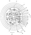
図10は、この発明の実施の形態の第5の参考例による車輪支持装置およびそれによって支持されるインホイールモータIWMの概略断面図である。
[ Reference Example 5 ]
FIG. 10 is a schematic cross-sectional view of a wheel support device according to a fifth reference example of the embodiment of the present invention and an in-wheel motor IWM supported by the wheel support device.

図10を参照して、車輪支持装置200Eは、車輪支持装置200Cのトルクロッド390(390a,390b)を、単一のトルクロッド490に代えたものである。   Referring to FIG. 10, wheel support device 200E is obtained by replacing torque rod 390 (390a, 390b) of wheel support device 200C with a single torque rod 490.

ダイナミックマスダンパ機構300,300Aは、車両の進行方向DR1に沿ってインホイールモータIWMの両側に配設される。また、ダイナミックマスダンパ機構300,300Aは、それぞれインホイールモータIWMの重心線L1上に中央部306が位置するように、インホイールモータIWMの外周側面に取り付けられる。   The dynamic mass damper mechanisms 300 and 300A are disposed on both sides of the in-wheel motor IWM along the traveling direction DR1 of the vehicle. The dynamic mass damper mechanisms 300 and 300A are attached to the outer peripheral side surface of the in-wheel motor IWM so that the central portion 306 is positioned on the center of gravity line L1 of the in-wheel motor IWM.

トルクロッド490は、一方端がインホイールモータIWMのケース60に連結され、他方端がナックル280に連結される。トルクロッド490は、トルクロッド390と同様に「回転抑制部材」を構成し、インホイールモータIWMの回転方向DR4への回転を抑制し、インホイールモータIWMの振動方向を車両の上下方向DR1に規制する。   Torque rod 490 has one end connected to case 60 of in-wheel motor IWM and the other end connected to knuckle 280. The torque rod 490 constitutes a “rotation suppressing member” in the same manner as the torque rod 390, suppresses the rotation of the in-wheel motor IWM in the rotation direction DR4, and restricts the vibration direction of the in-wheel motor IWM to the vehicle vertical direction DR1. To do.

このような構成とすることにより、インホイールモータIWMに生じた車両の上下方向DR1の振動は、インホイールモータIWMの両側に位置するダイナミックマスダンパ機構300,300Aに均等に伝達される。すなわち、ダイナミックマスダンパ機構300,300Aの各々が、インホイールモータIWMの振動を吸収するように働くことから、車輪支持装置200Bに対して、電動輪100に生じた振動をより効率良く吸収することができ、乗り心地がさらに向上する。   With this configuration, the vibration in the vertical direction DR1 of the vehicle generated in the in-wheel motor IWM is evenly transmitted to the dynamic mass damper mechanisms 300 and 300A located on both sides of the in-wheel motor IWM. That is, each of the dynamic mass damper mechanisms 300 and 300A works so as to absorb the vibration of the in-wheel motor IWM, so that the wheel support device 200B can more efficiently absorb the vibration generated in the electric wheel 100. And ride comfort is further improved.

また、トルクロッド490を単一としたことによって、インホイールモータIWMの外周側面へのダイナミックナスダンパ機構300,300AのインホイールモータIWMへの取り付けが容易となる。   Further, by using a single torque rod 490, the dynamic eggplant damper mechanisms 300, 300A can be easily attached to the in-wheel motor IWM on the outer peripheral side surface of the in-wheel motor IWM.

なお、本参考例において、等速ジョイント30は、インホイールモータIWMの回転軸方向への振動を考慮して、シャフト110を回転軸方向にスライド可能なタイプが適用される。 In this reference example, the constant velocity joint 30 is a type that can slide the shaft 110 in the direction of the rotation axis in consideration of vibration in the direction of the rotation axis of the in-wheel motor IWM.

今回開示された実施の形態はすべての点で例示であって制限的なものではないと考えられるべきである。本発明の範囲は、上記した実施の形態の説明ではなくて特許請求の範囲によって示され、特許請求の範囲と均等の意味および範囲内でのすべての変更が含まれることが意図される。   The embodiment disclosed this time should be considered as illustrative in all points and not restrictive. The scope of the present invention is shown not by the above description of the embodiments but by the scope of claims for patent, and is intended to include meanings equivalent to the scope of claims for patent and all modifications within the scope.

この発明は、耐久性が高い車輪支持装置に適用される。   The present invention is applied to a wheel support device having high durability.

この発明の実施の形態の第1の参考例による車輪支持装置およびそれによって支持される電動輪の概略断面図である。 1 is a schematic cross-sectional view of a wheel support device according to a first reference example of an embodiment of the present invention and an electric wheel supported by the wheel support device. 図1に示すA方向から見た電動輪および車輪支持装置の平面図である。It is a top view of the motor-driven wheel and wheel support apparatus seen from the A direction shown in FIG. 第2の参考例による車輪支持装置およびそれによって支持される電動輪の概略断面図である。It is a schematic sectional drawing of the wheel support apparatus by a 2nd reference example, and the electric wheel supported by it. 図3に示すA方向から見たインホイールモータおよび車輪支持装置の平面図である。It is a top view of the in-wheel motor and wheel support device seen from the A direction shown in FIG. この発明の実施の形態による車輪支持装置およびそれによって支持される電動輪の概略断面図である。It is a schematic cross-sectional view of a motor-driven wheel supported by the wheel supporting apparatus and its by form state of the present invention. 図5に示すA方向から見た電動輪および車輪支持装置の平面図である。It is a top view of the motor-driven wheel and wheel support device seen from the A direction shown in FIG. 図5におけるダイナミックマスダンパ機構の構成例を示す概略断面図である。It is a schematic sectional drawing which shows the structural example of the dynamic mass damper mechanism in FIG. この発明の実施の形態の第3の参考例による車輪支持装置およびそれによって支持されるインホイールモータIWMの概略断面図である。It is a schematic sectional drawing of the wheel support apparatus by the 3rd reference example of embodiment of this invention, and the in-wheel motor IWM supported by it. この発明の実施の形態の第4の参考例による車輪支持装置およびそれによって支持されるインホイールモータIWMの概略断面図である。It is a schematic sectional drawing of the wheel support apparatus by the 4th reference example of embodiment of this invention, and the in-wheel motor IWM supported by it. この発明の実施の形態の第5の参考例による車輪支持装置およびそれによって支持されるインホイールモータIWMの概略断面図である。It is a schematic sectional drawing of the wheel support apparatus by the 5th reference example of embodiment of this invention, and the in-wheel motor IWM supported by it.

符号の説明Explanation of symbols

1〜4 ネジ、10 ホイールディスク、10A ディスク部、10B リム部、11,12 ハブベアリング、20 ホイールハブ、30 等速ジョイント、31 インナー、32 ボール、40 ブレーキロータ、50 ブレーキキャリパ、50A 開口部、51 ブレーキピストン、52,53 ブレーキパッド、60 ケース、60A 端面、100 電動輪、110 シャフト、140,150 モータマウント、160,170 ボールジョイント、180 ナックル、190,290,390,390a,390b,490 トルクロッド、191,191A,191B,291 直線部、192,192A,192B,292 湾曲部、193,193A,193B,293 端部、194,194A,194B,294 部材、200,200A〜200E 車両支持装置,210 アッパーアーム、210A,210B 端部、220 ロアアーム、230 ショックアブソーバ、240 リンク、250 タイヤ、300,300A,310,310A ダイナミックマスダンパ機構、302,304 スプリング、306 中央部、308,326 ブッシュ、310 上部、312 下部、314 アブソーバ、316 シャフト、1941,1942,2941 孔、3100 シム、3102 スナップリング、3104,3106 ナット、IWM インホイールモータ。   1-4 screws, 10 wheel disc, 10A disc portion, 10B rim portion, 11, 12 hub bearing, 20 wheel hub, 30 constant velocity joint, 31 inner, 32 ball, 40 brake rotor, 50 brake caliper, 50A opening, 51 Brake piston, 52, 53 Brake pad, 60 Case, 60A End face, 100 Motorized wheel, 110 Shaft, 140, 150 Motor mount, 160, 170 Ball joint, 180 knuckle, 190, 290, 390, 390a, 390b, 490 Torque Rod, 191, 191A, 191B, 291 Straight part, 192, 192A, 192B, 292 Curved part, 193, 193A, 193B, 293 End part, 194, 194A, 194B, 294 Member, 200, 20 0A-200E vehicle support device, 210 upper arm, 210A, 210B end, 220 lower arm, 230 shock absorber, 240 link, 250 tire, 300, 300A, 310, 310A dynamic mass damper mechanism, 302, 304 spring, 306 center 308, 326 bush, 310 upper part, 312 lower part, 314 absorber, 316 shaft, 1941, 1942, 2941 hole, 3100 shim, 3102 snap ring, 3104, 3106 nut, IWM in-wheel motor.

Claims (3)

車輪のホイール内に設けられたインホイールモータに取り付けられ、前記車輪の振動と前記インホイールモータの振動とを互いに減衰するように配置された弾性部材と、
一方端が車体の上下方向に回動可能に前記車体に固定されたサスペンションアームと
前記サスペンションアームの他方端および前記弾性部材に連結され、前記車輪のホイールを回転可能に支持する回転支持部材と
一方端が前記インホイールモータに連結されるとともに、他方端が前記回転支持部材に連結され、前記車輪の回転による前記インホイールモータの回転を抑制する回転抑制部材とを備え、
前記弾性部材は、前記車体の進行方向の一方向側のみに前記インホイールモータに取り付けられ、
前記回転抑制部材は、前記一方向側のみに前記インホイールモータに取り付けられ、
前記弾性部材は、前記車体の進行方向から見たときに、前記インホイールモータとの固定点が、前記インホイールモータの重心を通り、かつ前記車体の上下方向に延在する重心線上に位置するように前記インホイールモータに固定される、車輪支持装置。
An elastic member attached to an in-wheel motor provided in a wheel of the wheel, and arranged to attenuate the vibration of the wheel and the vibration of the in-wheel motor;
A suspension arm fixed to the vehicle body so that one end of the vehicle body is rotatable in the vertical direction of the vehicle body ;
A rotation support member connected to the other end of the suspension arm and the elastic member and rotatably supporting a wheel of the wheel ;
A rotation suppression member that has one end connected to the in-wheel motor and the other end connected to the rotation support member, and suppresses rotation of the in-wheel motor due to rotation of the wheel;
The elastic member is attached to the in-wheel motor only on one direction side of the traveling direction of the vehicle body,
The rotation suppressing member is attached to the in-wheel motor only on the one-direction side,
When viewed from the traveling direction of the vehicle body, the elastic member is positioned on a center line extending through the center of gravity of the in-wheel motor and extending in the vertical direction of the body when viewed from the in-wheel motor. A wheel support device fixed to the in-wheel motor as described above .
前記弾性部材は、
前記インホイールモータとの固定点を中央部として、前記車体の上下方向に直列に配置された一対の弾性部材と、
前記一対の弾性部材の振動を減衰する振動減衰機構とを含み、
前記一対の弾性部材は、各々が、前記インホイールモータとの固定点と前記回転支持部材との間に予め自然長から圧縮された状態で組み付けられる、請求項に記載の車輪支持装置。
The elastic member is
A pair of elastic members arranged in series in the vertical direction of the vehicle body, with a fixed point with the in-wheel motor as a central portion,
A vibration damping mechanism for damping vibrations of the pair of elastic members,
2. The wheel support device according to claim 1 , wherein each of the pair of elastic members is assembled in a state of being compressed in advance from a natural length between a fixed point of the in-wheel motor and the rotation support member.
前記インホイールモータは、
動力を発生するモータと、
前記モータにより発生された動力を前記ホイールに伝達するモータ出力軸とを含み、
前記モータ出力軸は、前記動力を前記ホイールに伝達する等速ジョイントに連結され、かつ、前記モータを、前記モータ出力軸と前記等速ジョイントとの連結部分を支点として支持する、請求項1または請求項2に記載の車輪支持装置。
The in-wheel motor is
A motor for generating power;
A motor output shaft for transmitting the power generated by the motor to the wheel,
The motor output shaft is connected to a constant velocity joint for transmitting the power to the wheels, and the motor, for supporting the connection portion between the constant velocity joint and the motor output shaft as a fulcrum, claim 1 or The wheel support apparatus according to claim 2 .
JP2005008224A 2004-01-16 2005-01-14 Wheel support device Expired - Fee Related JP4607603B2 (en)

Priority Applications (1)

Application Number Priority Date Filing Date Title
JP2005008224A JP4607603B2 (en) 2004-01-16 2005-01-14 Wheel support device

Applications Claiming Priority (2)

Application Number Priority Date Filing Date Title
JP2004009139 2004-01-16
JP2005008224A JP4607603B2 (en) 2004-01-16 2005-01-14 Wheel support device

Publications (2)

Publication Number Publication Date
JP2005225486A JP2005225486A (en) 2005-08-25
JP4607603B2 true JP4607603B2 (en) 2011-01-05

Family

ID=35000516

Family Applications (1)

Application Number Title Priority Date Filing Date
JP2005008224A Expired - Fee Related JP4607603B2 (en) 2004-01-16 2005-01-14 Wheel support device

Country Status (1)

Country Link
JP (1) JP4607603B2 (en)

Families Citing this family (6)

* Cited by examiner, † Cited by third party
Publication number Priority date Publication date Assignee Title
JP4661483B2 (en) * 2005-09-20 2011-03-30 マツダ株式会社 Rear suspension device
JP4779582B2 (en) * 2005-11-10 2011-09-28 日産自動車株式会社 In-wheel drive unit suspension system
JP4965131B2 (en) * 2006-01-27 2012-07-04 トヨタ自動車株式会社 In-wheel motor
EP2758259A1 (en) * 2011-09-22 2014-07-30 Schaeffler Technologies GmbH & Co. KG Wheel suspension device with wheel bearing support connected thereto in a steerable manner and with an integrated wheel drive motor
JP6518516B2 (en) * 2015-05-28 2019-05-22 Ntn株式会社 Suspension structure of in-wheel motor drive device
KR102512092B1 (en) * 2021-08-02 2023-03-20 서한산업(주) Independent steering apparatus

Also Published As

Publication number Publication date
JP2005225486A (en) 2005-08-25

Similar Documents

Publication Publication Date Title
JP4133186B2 (en) In-wheel motor system for steering wheels
JP4139353B2 (en) Wheel support device
US7641010B2 (en) In-wheel motor with high durability
JP4113506B2 (en) Wheel support device
JP2005289324A (en) Vehicle having auxiliary driving motor for of rear wheel
JPWO2002083446A1 (en) In-wheel motor mounting method and in-wheel motor system
WO2005097533A1 (en) In-wheel motor system
JP2004090822A (en) Motor-equipped wheel device for vehicle
JP2007161022A (en) In-wheel motor system
JP4607603B2 (en) Wheel support device
WO2006030715A1 (en) Flexible coupling and in-wheel motor system
JP2010269665A (en) Wheel supporting device
JP4694148B2 (en) Motor parts
JP2007196697A (en) In-wheel motor system
JP5133572B2 (en) Mounting method and mounting structure of dynamic vibration absorber and in-wheel motor
JP4312078B2 (en) Electric wheel
JP2005178684A (en) In-wheel motor system
JP4350591B2 (en) In-wheel motor system
JP2007283987A (en) In-wheel motor system
JP2005047481A (en) In-wheel motor system
JP2007190966A (en) In-wheel motor system
JP4279213B2 (en) In-wheel motor system
JP2007168507A (en) In-wheel motor system
JP2005329767A (en) In-wheel motor system
CN114954638A (en) Corner module and steering system thereof

Legal Events

Date Code Title Description
A711 Notification of change in applicant

Free format text: JAPANESE INTERMEDIATE CODE: A711

Effective date: 20051129

A521 Written amendment

Free format text: JAPANESE INTERMEDIATE CODE: A821

Effective date: 20051129

A621 Written request for application examination

Free format text: JAPANESE INTERMEDIATE CODE: A621

Effective date: 20070718

A977 Report on retrieval

Free format text: JAPANESE INTERMEDIATE CODE: A971007

Effective date: 20080528

A131 Notification of reasons for refusal

Free format text: JAPANESE INTERMEDIATE CODE: A131

Effective date: 20080603

A521 Written amendment

Free format text: JAPANESE INTERMEDIATE CODE: A523

Effective date: 20080729

A02 Decision of refusal

Free format text: JAPANESE INTERMEDIATE CODE: A02

Effective date: 20090414

A521 Written amendment

Free format text: JAPANESE INTERMEDIATE CODE: A523

Effective date: 20090714

A911 Transfer of reconsideration by examiner before appeal (zenchi)

Free format text: JAPANESE INTERMEDIATE CODE: A911

Effective date: 20090828

A912 Removal of reconsideration by examiner before appeal (zenchi)

Free format text: JAPANESE INTERMEDIATE CODE: A912

Effective date: 20091211

A521 Written amendment

Free format text: JAPANESE INTERMEDIATE CODE: A523

Effective date: 20100820

A01 Written decision to grant a patent or to grant a registration (utility model)

Free format text: JAPANESE INTERMEDIATE CODE: A01

A61 First payment of annual fees (during grant procedure)

Free format text: JAPANESE INTERMEDIATE CODE: A61

Effective date: 20101007

FPAY Renewal fee payment (event date is renewal date of database)

Free format text: PAYMENT UNTIL: 20131015

Year of fee payment: 3

R250 Receipt of annual fees

Free format text: JAPANESE INTERMEDIATE CODE: R250

R250 Receipt of annual fees

Free format text: JAPANESE INTERMEDIATE CODE: R250

R250 Receipt of annual fees

Free format text: JAPANESE INTERMEDIATE CODE: R250

R250 Receipt of annual fees

Free format text: JAPANESE INTERMEDIATE CODE: R250

LAPS Cancellation because of no payment of annual fees