EP1380356B1 - Hochdruckreinigungsgerät - Google Patents
Hochdruckreinigungsgerät Download PDFInfo
- Publication number
- EP1380356B1 EP1380356B1 EP03015737A EP03015737A EP1380356B1 EP 1380356 B1 EP1380356 B1 EP 1380356B1 EP 03015737 A EP03015737 A EP 03015737A EP 03015737 A EP03015737 A EP 03015737A EP 1380356 B1 EP1380356 B1 EP 1380356B1
- Authority
- EP
- European Patent Office
- Prior art keywords
- frame
- guide
- pressure
- cleaning appliance
- appliance according
- Prior art date
- Legal status (The legal status is an assumption and is not a legal conclusion. Google has not performed a legal analysis and makes no representation as to the accuracy of the status listed.)
- Expired - Lifetime
Links
- 238000004140 cleaning Methods 0.000 abstract description 16
- 239000007788 liquid Substances 0.000 description 2
- 230000007704 transition Effects 0.000 description 2
- 238000006073 displacement reaction Methods 0.000 description 1
- 230000002349 favourable effect Effects 0.000 description 1
- 239000012530 fluid Substances 0.000 description 1
- 238000010137 moulding (plastic) Methods 0.000 description 1
- 230000002093 peripheral effect Effects 0.000 description 1
- 238000004904 shortening Methods 0.000 description 1
- XLYOFNOQVPJJNP-UHFFFAOYSA-N water Substances O XLYOFNOQVPJJNP-UHFFFAOYSA-N 0.000 description 1
- 238000004804 winding Methods 0.000 description 1
Images



Classifications
-
- B—PERFORMING OPERATIONS; TRANSPORTING
- B08—CLEANING
- B08B—CLEANING IN GENERAL; PREVENTION OF FOULING IN GENERAL
- B08B3/00—Cleaning by methods involving the use or presence of liquid or steam
- B08B3/02—Cleaning by the force of jets or sprays
- B08B3/026—Cleaning by making use of hand-held spray guns; Fluid preparations therefor
-
- B—PERFORMING OPERATIONS; TRANSPORTING
- B65—CONVEYING; PACKING; STORING; HANDLING THIN OR FILAMENTARY MATERIAL
- B65H—HANDLING THIN OR FILAMENTARY MATERIAL, e.g. SHEETS, WEBS, CABLES
- B65H75/00—Storing webs, tapes, or filamentary material, e.g. on reels
- B65H75/02—Cores, formers, supports, or holders for coiled, wound, or folded material, e.g. reels, spindles, bobbins, cop tubes, cans, mandrels or chucks
- B65H75/34—Cores, formers, supports, or holders for coiled, wound, or folded material, e.g. reels, spindles, bobbins, cop tubes, cans, mandrels or chucks specially adapted or mounted for storing and repeatedly paying-out and re-storing lengths of material provided for particular purposes, e.g. anchored hoses, power cables
- B65H75/38—Cores, formers, supports, or holders for coiled, wound, or folded material, e.g. reels, spindles, bobbins, cop tubes, cans, mandrels or chucks specially adapted or mounted for storing and repeatedly paying-out and re-storing lengths of material provided for particular purposes, e.g. anchored hoses, power cables involving the use of a core or former internal to, and supporting, a stored package of material
- B65H75/44—Constructional details
- B65H75/4402—Guiding arrangements to control paying-out and re-storing of the material
-
- B—PERFORMING OPERATIONS; TRANSPORTING
- B08—CLEANING
- B08B—CLEANING IN GENERAL; PREVENTION OF FOULING IN GENERAL
- B08B2203/00—Details of cleaning machines or methods involving the use or presence of liquid or steam
- B08B2203/02—Details of machines or methods for cleaning by the force of jets or sprays
- B08B2203/0276—Hose reels specific for high pressure cleaners
Definitions
- the invention relates to a high-pressure cleaner with a frame having a bottom and a top and carries a motor and a driven by this high-pressure pump, and with a mounted above the pump and motor on the frame receptacle for a one-sided with the pressure outlet of the pump in communication High-pressure hose, which is removable from the receptacle.
- a relatively long high-pressure hose is normally used, so that the user can reach well from the point of view of the high-pressure cleaner at different distances from this remote cleaning areas. It is known to receive the high-pressure hose on a recording of the high-pressure cleaner, such as a hose drum, so that the user subtracts the desired length of the high-pressure hose from this recording if necessary and returns them to the recording, so for example wound on the hose reel, if only a shorter high pressure hose is needed.
- High pressure cleaning devices are known (EP-A-0 904 855 ), which are arranged on a frame in the lower area of the pump, the pump drive and possibly other units, while a receptacle for the high-pressure hose above the components takes place.
- EP-A-0 904 855 High pressure cleaning devices are known ( EP-A-0 904 855 ), which are arranged on a frame in the lower area of the pump, the pump drive and possibly other units, while a receptacle for the high-pressure hose above the components takes place.
- EP-A-0 904 855 It is an object of this invention to design a generic high-pressure cleaning device so that even when removing the high-pressure hose whose stability is not affected.
- the receptacle can be designed differently, particularly advantageous is the use of a rotatable drum, preferably this drum can also be spring loaded, so that when shortening the high pressure hose this is automatically wound onto the drum.
- the removal guide is arranged on a lower outer edge of the frame.
- the high-pressure hose is guided on the underside of the frame in front of the removal guide along the underside of the frame, in particular the high-pressure hose runs on the underside of the frame over its entire extent from one side of the frame to the opposite side.
- the high-pressure hose extends from the receptacle to the underside of the frame next to the frame.
- the high-pressure hose routed past the frame has a very small space requirement, and this course on the outside of the frame gives the designer the opportunity to install the necessary components in the interior of the frame irrespective of to accommodate the course of the high pressure hose.
- the frame has a recess through which the high-pressure hose passes. This return protects the high pressure hose against damage or accidental contact by the user.
- the recess may be formed as extending over a side surface of the frame groove.
- the groove narrows towards the underside of the frame, in particular V-shaped.
- the side walls of the groove then form a guide for the high-pressure hose, which allow it to migrate when winding on the recording transversely to the axis of rotation and thus deposit in adjacent layers on the recording.
- the narrowing groove forms a guide for the high-pressure hose, for example, this groove leads the high-pressure hose in a central arrangement in the center plane of the high-pressure cleaner.
- the return is at least partially covered to the outside, thereby the protection is increased.
- At least one second guide is arranged for the high-pressure hose between the receptacle and the removal guide.
- This further guide can be designed, in particular, as a deflecting guide, which deflects the part of the high-pressure hose extending from top to bottom into a section extending along the underside of the frame.
- the deflecting guide is arranged on a lower outer edge of the frame.
- At least one further supporting guide acting as a supporting surface is arranged between the peeling guide and the deflecting guide.
- This support guide may be formed, for example, as a rotatable roller or roller.
- the removal guide can according to a preferred embodiment of the invention have a passage opening for the high-pressure hose, which is bounded laterally by guide surfaces. It is advantageous if at least one guide surface is limited by a rotatable guide roller. There may be provided a plurality of such guide rollers whose axes of rotation are inclined relative to each other, preferably extend at least two of the guide rollers, the axes of rotation transversely to each other.
- the frame can be designed very differently, "frame” is understood in the invention, any device that receives the pump and the motor and possibly other technical units in operation of the high-pressure cleaner, it may be a simple frame to a partial or completely closed housing to a plastic molding with integrated liquid tanks etc.
- the frame comprises a housing which houses the motor and the pump, and that the high-pressure hose along a side wall and along the underside of the housing extends to Abzieh entry.
- the receptacle is arranged above the housing.
- the receptacle can be surrounded by a handle connected to the frame, which is formed, for example, to the housing and U-shaped, in this way one obtains optimal space utilization for receiving the different components.
- the high-pressure cleaner 1 shown in the drawing comprises a substantially cuboid closed housing 2, which has in its interior a motor and a pump and other technical units, which are necessary to a cleaning fluid, such as water, from a supply line to high pressure bring and then supply a high pressure line.
- a cleaning fluid such as water
- the housing 2 has a substantially flat underside 4 and a front side 5 extending approximately perpendicularly therefrom and a rear side 6 which also extends approximately perpendicularly therefrom and which are interconnected via an upper side 7 which runs approximately parallel to the underside 4.
- a front edge 8 is formed, in the transition region between the back 6 and the bottom 4, a rear edge.
- two wheels 10 are mounted rotatably about a parallel to the rear edge 9 extending axis of rotation on the housing 2, in the region of the front edge 8 are on the housing 2 in the drawing not shown supports, so that the housing 2 normally on these supports and the wheels 10 rests on a footprint.
- a U-shaped handle 11 connects with a parallel to the top 7 extending grip web 12 and two transverse thereto, opening into the housing 2 side rails 13, 14. With the help of this handle 11, the high-pressure cleaning device 1 are moved by means of the wheels 10.
- the handle 11 forms above the housing 2 between the handle bar 12 and the two bars 13, 14 a receiving space in which between the two bars 13 and 14 a hose drum 15 is mounted, this is rotatable about its longitudinal axis, this longitudinal axis runs parallel to
- a flexible high-pressure hose 16 is wound, the end wound on the hose reel 15 in the manner not apparent from the drawing with the pressure outlet of the high-pressure pump in the interior of the housing 2 is in communication.
- a bearing shaft of the hose drum 15 is used as a supply line for the pumped from the pump to the high-pressure hose liquid.
- the high-pressure hose 16 runs parallel to the rear side 6 of the housing 2 at a slight distance from this rear side 6 into the region of the rear edge 9 and from there directly to the underside 4 of the housing 2 along the front edge 8.
- a removal guide 18 is arranged in the middle, through which the high-pressure hose 16 passes and which passes the high-pressure hose transversely to its longitudinal direction through a defined passage opening whose cross-section is only slightly larger than the cross-section of the high-pressure hose 16.
- An example of Such Abzieh Adjust 18 is in FIG. 5 shown.
- a rectangular frame 19 In a rectangular frame 19, three guide rollers 20, 21, 22 rotatably mounted about mutually perpendicular, parallel to the sides of the frame 19 extending axes of rotation, these form between them the passage opening 23, which limits on the fourth side by the frame 19 itself becomes.
- a guide roller 23 is also arranged in the middle, which deflects the high pressure hose from the vertical to the horizontal, and between this guide roller 23 and the Abzieh Assembly 18 is approximately in the middle of the bottom 4 is still a support roller 24 is arranged at which the high-pressure hose 16 abuts.
- the back 6 of the housing 2 has a continuous from top to bottom, arranged in the middle longitudinal groove 25 which narrows V-shaped from top to bottom and which is so narrow in the region of the rear edge 9, that the high-pressure hose 16 against a lateral Guided displacement in the middle of the rear edge and there directly to the guide roller 23 is supplied.
- the longitudinal groove 25 permits the high-pressure hose 16 to move laterally at the upper end of the longitudinal groove, so that the high-pressure hose can move over the entire width of the hose reel 15 and deposit it in layers on the peripheral surface 17.
- the resulting forces in the region of the removal guide 18 are introduced into the high-pressure cleaning device 1 when the high-pressure hose 16 is removed, ie at the lower end of the high-pressure cleaning device 1 and also in the middle of the leading edge. It is practiced practically no tilting moment on the high-pressure cleaner, and yet it is possible to store the hose drum 15 at a great distance from the bottom of the high-pressure cleaner 1 at this and thereby achieve a very compact arrangement of all desired parts of the high-pressure cleaner.
- the high-pressure hose 16 is guided around the housing 2 on defined paths and is also protected in the area of the high-pressure cleaning device 1 over its entire course, if necessary, also covers can be provided to improve this protection.
Landscapes
- Cleaning By Liquid Or Steam (AREA)
- Cleaning In General (AREA)
- Mechanical Sealing (AREA)
- Treatment Of Fiber Materials (AREA)
- Mechanical Treatment Of Semiconductor (AREA)
Description
- Die Erfindung betrifft ein Hochdruckreinigungsgerät mit einem Rahmen, der eine Unterseite und eine Oberseite aufweist und einen Motor sowie eine von diesem angetriebenen Hochdruckpumpe trägt, und mit einer oberhalb von Pumpe und Motor am Rahmen gelagerten Aufnahme für einen einseitig mit dem Druckauslaß der Pumpe in Verbindung stehenden Hochdruckschlauch, der von der Aufnahme abziehbar ist.
- Bei Hochdruckreinigungsgeräten wird normalerweise ein relativ langer Hochdruckschlauch verwendet, damit der Benutzer vom Standpunkt des Hochdruckreinigungsgerätes aus unterschiedlich weit von diesem entfernte Reinigungsbereiche gut erreichen kann. Es ist dabei bekannt, den Hochdruckschlauch auf einer Aufnahme des Hochdruckreinigungsgerätes aufzunehmen, beispielsweise einer Schlauchtrommel, so daß der Benutzer bei Bedarf die gewünschte Länge des Hochdruckschlauches von dieser Aufnahme abzieht und sie wieder an die Aufnahme zurückgibt, also beispielsweise auf der Schlauchtrommel aufwickelt, wenn nur ein kürzerer Hochdruckschlauch benötigt wird.
- Es sind Hochdruckreinigungsgeräte bekannt (
EP-A-0 904 855 ), bei denen an einem Rahmen im unteren Bereich die Pumpe, der Pumpenantrieb und eventuell andere Aggregate angeordnet sind, während eine Aufnahme für den Hochdruckschlauch oberhalb der Bauteile Platz findet. Es ergibt sich dann zwar eine relativ günstige und platzsparende Anordnung all dieser Teile, es besteht aber unter Umständen die Gefahr, daß der Benutzer beim Abziehen des Hochdruckschlauches ein so großes Drehmoment auf das Hochdruckreinigungsgerät ausübt, daß dieses umkippt. Je höher die Schlauchaufnahme beim Hochdruckreinigungsgerät angeordnet ist, desto größer wird diese Gefahr. - Das Dokument,
EP-A-0 904 855 umfasst ein Hochdruckreinigungsgerät gemäss dem oberbegriff des Anspruchs 1. Es ist Aufgabe dieser Erfindung, ein gattungsgemäßes Hochdruckreinigungsgerät so auszubilden, daß auch beim Abziehen des Hochdruckschlauches dessen Standfestigkeit nicht beeinträchtigt wird. - Eine lösung für diese Aufgabe wird bereits in
EP-A-0 770 575 vorgeschlagen. - Diese Aufgabe wird in der Erfindung bei einem Hochdruckreinigungsgerät der eingangs beschriebenen Art erfindungsgemäß dadurch gelöst, daß am Rahmen an dessen Unterseite eine Abziehführung für den Hochdruckschlauch angeordnet ist und daß der Hochdruckschlauch am Rahmen von der Aufnahme zu der Abziehführung verläuft. Bei einer solchen Ausgestaltung ist sichergestellt, daß die Abziehkräfte, die über den Hochdruckschlauch auf das Hochdruckreinigungsgerät übertragen werden, im Bereich der Abziehführung auf das Hochdruckreinigungsgerät wirken, und da diese Abziehführung am unteren Ende des Hochdruckreinigungsgerätes angeordnet ist, werden also diese Kräfte am unteren Ende in das Hochdruckreinigungsgerät eingeleitet. Kippmomente werden dadurch fast vollständig vermieden.
- Die Aufnahme kann unterschiedlich ausgebildet sein, besonders vorteilhaft ist die Verwendung einer drehbaren Trommel, vorzugsweise kann diese Trommel auch federbelastet sein, so daß beim Verkürzen des Hochdruckschlauches dieser selbsttätig auf die Trommel aufgewickelt wird.
- Besonders günstig ist es, wenn die Abziehführung an einer unteren Außenkante des Rahmens angeordnet ist.
- Bei einer bevorzugten Ausführungsform ist vorgesehen, daß der Hochdruckschlauch an der Unterseite des Rahmens vor der Abziehführung längs der Unterseite des Rahmens geführt ist, insbesondere verläuft der Hochdruckschlauch an der Unterseite des Rahmens über dessen gesamte Ausdehnung von einer Seite des Rahmens bis zur gegenüberliegenden Seite.
- Es ist weiterhin vorteilhaft, wenn der Hochdruckschlauch von der Aufnahme zur Unterseite des Rahmens neben dem Rahmen verläuft. Dadurch ist im Bereich des Rahmens ausreichend Platz zur Aufnahme aller notwendigen Aggregate, der seitlich am Rahmen vorbeigeführte Hochdruckschlauch hat einen sehr geringen Platzbedarf, und dieser Verlauf an der Außenseite des Rahmens gibt dem Konstrukteur die Möglichkeit, im Inneren des Rahmens die notwendigen Bauteile ohne Rücksicht auf den Verlauf des Hochdruckschlauches unterzubringen.
- Besonders vorteilhaft ist es, wenn der Rahmen einen Rücksprung aufweist, durch den der Hochdruckschlauch hindurchläuft. Dieser Rücksprung schützt den Hochdruckschlauch gegen Beschädigung oder gegen ungewollte Berührung durch den Benutzer.
- Beispielsweise kann der Rücksprung als sich über eine Seitenfläche des Rahmens erstreckende Nut ausgebildet sein.
- Dabei ist es günstig, wenn die Nut sich zur Unterseite des Rahmens hin verengt, insbesondere V-förmig. Die Seitenwände der Nut bilden dann eine Führung für den Hochdruckschlauch, die diesem ermöglichen, beim Aufwickeln auf die Aufnahme quer zu deren Drehachse zu wandern und sich so in nebeneinander liegenden Lagen auf der Aufnahme abzulegen. An der gegenüberliegenden Seite dagegen bildet die sich verengende Nut eine Führung für den Hochdruckschlauch, beispielsweise führt diese Nut den Hochdruckschlauch bei einer zentralen Anordnung in der Mittelebene des Hochdruckreinigungsgerätes.
- Zusätzlich kann vorgesehen sein, daß der Rücksprung zumindest teilweise nach außen hin abgedeckt ist, dadurch wird der Schutz noch erhöht.
- Günstig ist es, wenn mindestens eine zweite Führung für den Hochdruckschlauch zwischen der Aufnahme und der Abziehführung angeordnet ist.
- Diese weitere Führung kann insbesondere als Umlenkführung ausgebildet sein, die den von oben nach unten verlaufenden Teil des Hochdruckschlauches in einen längs der Unterseite des Rahmens verlaufenden Abschnitt umlenkt.
- Günstig ist es, wenn die Umlenkführung an einer unteren Außenkante des Rahmens angeordnet ist.
- Bei einer bevorzugten Ausführungsform der Erfindung ist mindestens eine weitere als Stützfläche wirkende Stützführung zwischen der Abziehführung und der Umlenkführung angeordnet. Diese Stützführung kann beispielsweise als drehbare Rolle oder Walze ausgebildet sein.
- Die Abziehführung kann gemäß einer bevorzugten Ausführungsform der Erfindung eine Durchtrittsöffnung für den Hochdruckschlauch aufweisen, die seitlich durch Führungsflächen begrenzt ist. Dabei ist es vorteilhaft, wenn mindestens eine Führungsfläche durch eine drehbare Führungsrolle begrenzt wird. Es können mehrere derartige Führungsrollen vorgesehen sein, deren Drehachsen gegeneinander geneigt sind, vorzugsweise verlaufen bei mindestens zwei der Führungsrollen die Drehachsen quer zueinander.
- Der Rahmen kann sehr unterschiedlich ausgebildet sein, unter "Rahmen" wird bei der Erfindung jede Vorrichtung verstanden, die die Pumpe und den Motor und gegebenenfalls weitere technische Aggregate im Betrieb des Hochdruckreinigungsgerätes aufnimmt, dabei kann es sich um ein einfaches Rahmengestell handeln, um ein teilweise oder ganz geschlossenes Gehäuse, um ein Kunststofformteil mit integrierten Flüssigkeitstanks etc.
- Bei einer besonders bevorzugten Ausführungsform ist vorgesehen, daß der Rahmen ein Gehäuse umfaßt, das den Motor und die Pumpe aufnimmt, und daß der Hochdruckschlauch längs einer Seitenwand und längs der Unterseite des Gehäuses zur Abziehführung verläuft.
- Dabei ist es vorteilhaft, wenn die Aufnahme oberhalb des Gehäuses angeordnet ist.
- Insbesondere kann die Aufnahme von einem mit dem Rahmen verbundenen Handgriff umgeben werden, der beispielsweise an das Gehäuse angeformt ist und U-förmig ausgebildet ist, auf diese Weise erhält man eine optimale Platzausnützung zur Aufnahme der unterschiedlichen Bauteile.
- Die nachfolgende Beschreibung einer bevorzugten Ausführungsform der Erfindung dient im Zusammenhang mit der Zeichnung der näheren Erläuterung. Es zeigen:
- Figur 1:
- eine Querschnittsansicht durch ein fahrbares Hochdruckreinigungsgerät mit einer Schlauchtrommel und einer Schlauchführung längs der Rückwand und der Unterseite des Gerätes;
- Figur 2:
- eine perspektivische Rückansicht des Hochdruckreinigungsgerätes der
Figur 1 ; - Figur 3:
- eine perspektivische Ansicht des Hochdruckreinigungsgerätes der
Figur 1 von der Unterseite her; - Figur 4:
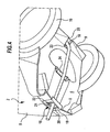
- eine perspektivische Detailansicht der Unterseite des Hochdruckreinigungsgerätes der
Figur 1 und - Figur 5:
- eine Draufsicht auf die Abziehführung für den Hochdruckschlauch.
- Das in der Zeichnung dargestellte Hochdruckreinigungsgerät 1 umfaßt ein im wesentlichen quaderförmiges geschlossenes Gehäuse 2, welches in seinem Inneren einen Motor und eine Pumpe sowie weitere technische Aggregate aufweist, die dazu nötig sind, um eine Reinigungsflüssigkeit, beispielsweise Wasser, von einer Versorgungsleitung auf hohen Druck zu bringen und dann einer Hochdruckleitung zuzuführen. Diese Aggregate sind in der Zeichnung nur schematisch angedeutet und pauschal mit dem Bezugszeichen 3 versehen.
- Das Gehäuse 2 weist eine im wesentlichen ebene Unterseite 4 auf sowie eine etwa senkrecht davon abgehende Vorderseite 5 und eine ebenfalls etwa senkrecht davon abgehende Rückseite 6, die über eine Oberseite 7 miteinander verbunden sind, die etwa parallel zur Unterseite 4 verläuft. Im Übergangsbereich zwischen der Vorderseite 5 und der Unterseite 4 ist eine Vorderkante 8 ausgebildet, im Übergangsbereich zwischen der Rückseite 6 und der Unterseite 4 eine Rückkante 9.
- Im Bereich dieser Rückkante 9 sind am Gehäuse 2 zwei Räder 10 um eine parallel zur Rückkante 9 verlaufende Drehachse drehbar gelagert, im Bereich der Vorderkante 8 befinden sich am Gehäuse 2 in der Zeichnung nicht näher dargestellte Stützen, so daß das Gehäuse 2 normalerweise auf diesen Stützen und den Rädern 10 auf einer Stellfläche ruht.
- An die Oberseite 7 des Gehäuses 2 schließt sich ein U-förmiger Handgriff 11 an mit einem parallel zur Oberseite 7 verlaufenden Griffsteg 12 und zwei quer dazu verlaufenden, in das Gehäuse 2 einmündenden seitlichen Holmen 13, 14. Mit Hilfe dieses Handgriffes 11 kann das Hochdruckreinigungsgerät 1 mittels der Räder 10 verfahren werden.
- Der Handgriff 11 bildet oberhalb des Gehäuses 2 zwischen dem Griffsteg 12 und den beiden Holmen 13, 14 einen Aufnahmeraum aus, in dem zwischen den beiden Holmen 13 und 14 eine Schlauchtrommel 15 gelagert ist, diese ist um ihre Längsachse verdrehbar, diese Längsachse läuft parallel zum Griffsteg 12. Auf diese Schlauchtrommel 15 ist ein flexibler Hochdruckschlauch 16 aufgewickelt, dessen auf die Schlauchtrommel 15 aufgewickeltes Ende in aus der Zeichnung nicht ersichtlicher Weise mit dem Druckauslaß der Hochdruckpumpe im Inneren des Gehäuses 2 in Verbindung steht. Dazu sind dem Fachmann die notwendigen Verbindungsmittel bekannt, beispielsweise wird eine Lagerwelle der Schlauchtrommel 15 als Zuleitung für die von der Pumpe zum Hochdruckschlauch geförderte Flüssigkeit verwendet.
- Von der Umfangsfläche 17 der Schlauchtrommel 15 verläuft der Hochdruckschlauch 16 parallel zur Rückseite 6 des Gehäuses 2 in geringfügigem Abstand von dieser Rückseite 6 bis in den Bereich der Rückkante 9 und von dort unmittelbar an der Unterseite 4 des Gehäuses 2 entlang bis zur Vorderkante 8.
- Im Bereich der Vorderkante 8 ist in deren Mitte eine Abziehführung 18 angeordnet, durch die der Hochdruckschlauch 16 hindurchläuft und die den Hochdruckschlauch quer zu seiner Längsrichtung durch eine definierte Durchtrittsöffnung hindurchführt, deren Querschnitt nur geringfügig größer ist als der Querschnitt des Hochdruckschlauches 16. Ein Beispiel einer solchen Abziehführung 18 ist in
Figur 5 dargestellt. In einem rechteckigen Rahmen 19 sind drei Führungsrollen 20, 21, 22 um jeweils senkrecht aufeinanderstehende, parallel zu den Seiten des Rahmens 19 verlaufende Drehachsen verdrehbar gelagert, diese bilden zwischen sich die Durchtrittsöffnung 23 aus, die an der vierten Seite durch den Rahmen 19 selbst begrenzt wird. - Im Bereich der Rückkante 9 ist ebenfalls in deren Mitte eine Umlenkrolle 23 angeordnet, die den Hochdruckschlauch von der Senkrechten in die Horizontale umlenkt, und zwischen dieser Umlenkrolle 23 und der Abziehführung 18 ist etwa in der Mitte der Unterseite 4 noch eine Stützrolle 24 angeordnet, an welcher der Hochdruckschlauch 16 anliegt.
- Die Rückseite 6 des Gehäuses 2 weist eine von oben nach unten durchlaufende, in der Mitte angeordnete Längsnut 25 auf, die sich V-förmig von oben nach unten verengt und die im Bereich der Rückkante 9 so schmal ist, daß der Hochdruckschlauch 16 gegen eine seitliche Verschiebung in der Mitte der Rückkante geführt und dort direkt der Umlenkrolle 23 zugeführt wird. Durch die V-förmige Aufweitung erlaubt die Längsnut 25 dem Hochdruckschlauch 16 dagegen am oberen Ende der Längsnut eine seitliche Bewegung, so daß der Hochdruckschlauch sich über die gesamte Breite der Schlauchtrommel 15 bewegen und lagenweise auf der Umfangsfläche 17 ablegen kann.
- Durch die beschriebene Führung des Hochdruckschlauches 16 am Hochdruckreinigungsgerät 1 werden beim Abziehen des Hochdruckschlauches 16 die dadurch entstehenden Kräfte im Bereich der Abziehführung 18 in das Hochdruckreinigungsgerät 1 eingeleitet, also an dem unteren Ende des Hochdruckreinigungsgerätes 1 und außerdem in der Mitte der Vorderkante. Es wird dadurch praktisch kein Kippmoment auf das Hochdruckreinigungsgerät ausgeübt, und trotzdem ist es möglich, die Schlauchtrommel 15 in großem Abstand von der Unterseite des Hochdruckreinigungsgerätes 1 an diesem zu lagern und dadurch eine sehr kompakte Anordnung aller gewünschten Teile des Hochdruckreinigungsgerätes zu erreichen.
- Der Hochdruckschlauch 16 wird um das Gehäuse 2 auf definierten Wegen herumgeführt und ist dabei auch im Bereich des Hochdruckreinigungsgerätes 1 über seinen gesamten Verlauf geschützt, gegebenenfalls können auch Abdekkungen vorgesehen sein, um diesen Schutz noch zu verbessern.
Claims (22)
- Hochdruckreinigungsgerät (1) mit einem Rahmen (2), der eine Unterseite (4) und eine Oberseite (7) aufweist und einen Motor sowie eine von diesem angetriebenen Hochdruckpumpe trägt, und mit einer oberhalb von Pumpe und Motor (3) am Rahmen (2) gelagerten Aufnahme (15) für einen einseitig mit dem Druckauslaß der Pumpe in Verbindung stehenden Hochdruckschlauch (16), der von der Aufnahme abziehbar ist, dadurch gekennzeichnet, daß am Rahmen (2) an dessen Unterseite (4) eine Abziehführung (18) für den Hochdruckschlauch (16) angeordnet ist und daß der Hochdruckschlauch (16) am Rahmen (2) von der Aufnahme (15) zu der Abziehführung (18) verläuft.
- Hochdruckreinigungsgerät nach Anspruch 1, dadurch gekennzeichnet, daß die Aufnahme (15) eine drehbare Trommel ist.
- Hochdruckreinigungsgerät nach einem der Ansprüche 1 oder 2, dadurch gekennzeichnet, daß die Abziehführung (18) an einer unteren Außenkante (8) des Rahmens (2) angeordnet ist.
- Hochdruckreinigungsgerät nach einem der voranstehenden Ansprüche, dadurch gekennzeichnet, daß der Hochdruckschlauch (16) an der Unterseite (4) des Rahmens (2) vor der Abziehführung (18) längs der Unterseite (4) des Rahmens (2) geführt ist.
- Hochdruckreinigungsgerät nach Anspruch 4, dadurch gekennzeichnet, daß der Hochdruckschlauch (16) an der Unterseite (4) des Rahmens (2) über dessen gesamte Ausdehnung von einer Seite des Rahmens (2) bis zur gegenüberliegenden Seite verläuft.
- Hochdruckreinigungsgerät nach einem der voranstehenden Ansprüche, dadurch gekennzeichnet, daß der Hochdruckschlauch (16) von der Aufnahme (15) zur Unterseite (4) des Rahmens (2) neben dem Rahmen (2) verläuft.
- Hochdruckreinigungsgerät nach Anspruch 6, dadurch gekennzeichnet, daß der Rahmen (2) einen Rücksprung (25) aufweist, durch den der Hochdruckschlauch (16) hindurchläuft.
- Hochdruckreinigungsgerät nach Anspruch 7, dadurch gekennzeichnet, daß der Rücksprung (25) als sich über eine Seitenfläche (6) des Rahmens (2) erstreckende Nut ausgebildet ist.
- Hochdruckreinigungsgerät nach Anspruch 8, dadurch gekennzeichnet, daß der Rücksprung (25) sich zur Unterseite (4) des Rahmens (2) hin verengt.
- Hochdruckreinigungsgerät nach Anspruch 9, dadurch gekennzeichnet, daß der Rücksprung (25) sich zur Unterseite (4) des Rahmens (2) V-förmig verengt.
- Hochdruckreinigungsgerät nach einem der Ansprüche 7 bis 10, dadurch gekennzeichnet, daß der Rücksprung (25) zumindest teilweise nach außen hin abgedeckt ist.
- Hochdruckreinigungsgerät nach einem der voranstehenden Ansprüche, dadurch gekennzeichnet, daß mindestens eine zweite Führung (23) für den Hochdruckschlauch (16) zwischen der Aufnahme (15) und der Abziehführung (18) angeordnet ist.
- Hochdruckreinigungsgerät nach Anspruch 12, dadurch gekennzeichnet, daß eine weitere Führung (23) als Umlenkführung ausgebildet ist, die den von oben nach unten verlaufenden Teil des Hochdruckschlauches (16) in einen längs der Unterseite (4) des Rahmens (2) verlaufenden Abschnitt umlenkt.
- Hochdruckreinigungsgerät nach Anspruch 13, dadurch gekennzeichnet, daß die Umlenkführung (23) an einer unteren Außenkante (9) des Rahmens (2) angeordnet ist.
- Hochdruckreinigungsgerät nach Anspruch 13 oder 14, dadurch gekennzeichnet, daß mindestens eine weitere als Stützfläche wirkende Stützführung (24) zwischen der Abziehführung (18) und der Umlenkführung (23) angeordnet ist.
- Hochdruckreinigungsgerät nach Anspruch 15, dadurch gekennzeichnet, daß die Stützführung (24) als drehbare Rolle oder Walze ausgebildet ist.
- Hochdruckreinigungsgerät nach einem der voranstehenden Ansprüche, dadurch gekennzeichnet, daß die Abziehführung (18) eine Durchtrittsöffnung für den Hochdruckschlauch (16) aufweist, die seitlich durch Führungsflächen (19, 20, 21, 22) begrenzt wird.
- Hochdruckreinigungsgerät nach Anspruch 17, dadurch gekennzeichnet, daß mindestens eine Führungsfläche (20, 21, 22) durch eine drehbare Führungsrolle gebildet wird.
- Hochdruckreinigungsgerät nach Anspruch 18, dadurch gekennzeichnet, daß mindestens zwei Führungsrollen (20, 21, 22) mit quer zueinander verlaufenden Drehachsen vorgesehen sind.
- Hochdruckreinigungsgerät nach einem der voranstehenden Ansprüche, dadurch gekennzeichnet, daß der Rahmen ein Gehäuse (2) umfaßt, das den Motor und die Pumpe aufnimmt, und daß der Hochdruckschlauch (16) längs einer Seitenwand (6) und längs der Unterseite (4) des Gehäuses (2) zur Abziehführung (18) verläuft.
- Hochdruckreinigungsgerät nach Anspruch 20, dadurch gekennzeichnet, daß die Aufnahme (15) oberhalb des Gehäuses (2) angeordnet ist.
- Hochdruckreinigungsgerät nach einem der voranstehenden Ansprüche, dadurch gekennzeichnet, daß die Aufnahme (15) von einem mit dem Rahmen (2) verbundenen Handgriff (11) umgeben wird.
Applications Claiming Priority (2)
| Application Number | Priority Date | Filing Date | Title |
|---|---|---|---|
| DE10232132 | 2002-07-11 | ||
| DE10232132A DE10232132B4 (de) | 2002-07-11 | 2002-07-11 | Hochdruckreinigungsgerät |
Publications (3)
| Publication Number | Publication Date |
|---|---|
| EP1380356A2 EP1380356A2 (de) | 2004-01-14 |
| EP1380356A3 EP1380356A3 (de) | 2005-05-25 |
| EP1380356B1 true EP1380356B1 (de) | 2008-09-10 |
Family
ID=29723907
Family Applications (1)
| Application Number | Title | Priority Date | Filing Date |
|---|---|---|---|
| EP03015737A Expired - Lifetime EP1380356B1 (de) | 2002-07-11 | 2003-07-10 | Hochdruckreinigungsgerät |
Country Status (5)
| Country | Link |
|---|---|
| EP (1) | EP1380356B1 (de) |
| AT (1) | ATE407752T1 (de) |
| DE (2) | DE10232132B4 (de) |
| DK (1) | DK1380356T3 (de) |
| ES (1) | ES2312692T3 (de) |
Families Citing this family (3)
| Publication number | Priority date | Publication date | Assignee | Title |
|---|---|---|---|---|
| DE102007018250A1 (de) * | 2007-04-12 | 2008-10-16 | Alfred Kärcher Gmbh & Co. Kg | Hochdruckreinigungsgerät |
| CN103252323A (zh) * | 2012-02-21 | 2013-08-21 | 艾纶锐祈清洁设备(上海)有限公司 | 一种高压清洗系统 |
| DE112018007503A5 (de) * | 2018-04-23 | 2021-03-11 | Alfred Kärcher SE & Co. KG | Hochdruckreinigungsgerät |
Family Cites Families (4)
| Publication number | Priority date | Publication date | Assignee | Title |
|---|---|---|---|---|
| US2640724A (en) * | 1950-03-20 | 1953-06-02 | Sanders | Engine cleaning equipment |
| DK0770575T3 (da) * | 1995-10-30 | 2000-09-04 | Kew Ind As | Højtryksrenser med slangerulle |
| DE29717390U1 (de) * | 1997-09-30 | 1998-02-26 | Wap Reinigungssysteme Gmbh & Co, 89287 Bellenberg | Hochdruckreinigungsgerät mit Schlauchtrommel |
| DE29720383U1 (de) * | 1997-11-19 | 1998-02-12 | Elektra Beckum Ag, 49716 Meppen | Hochdruckreinigungsgerät |
-
2002
- 2002-07-11 DE DE10232132A patent/DE10232132B4/de not_active Expired - Fee Related
-
2003
- 2003-07-10 EP EP03015737A patent/EP1380356B1/de not_active Expired - Lifetime
- 2003-07-10 DE DE50310463T patent/DE50310463D1/de not_active Expired - Lifetime
- 2003-07-10 ES ES03015737T patent/ES2312692T3/es not_active Expired - Lifetime
- 2003-07-10 DK DK03015737T patent/DK1380356T3/da active
- 2003-07-10 AT AT03015737T patent/ATE407752T1/de active
Also Published As
| Publication number | Publication date |
|---|---|
| ATE407752T1 (de) | 2008-09-15 |
| DE50310463D1 (de) | 2008-10-23 |
| EP1380356A3 (de) | 2005-05-25 |
| DE10232132B4 (de) | 2004-05-13 |
| DE10232132A1 (de) | 2004-02-05 |
| EP1380356A2 (de) | 2004-01-14 |
| DK1380356T3 (da) | 2009-03-23 |
| ES2312692T3 (es) | 2009-03-01 |
Similar Documents
| Publication | Publication Date | Title |
|---|---|---|
| DE20115003U1 (de) | Abdichtsystem | |
| EP2131969B1 (de) | Hochdruckreinigungsgerät | |
| DE2630788A1 (de) | Anlage zur kontinuierlichen oberflaechenbehandlung von metallischen werkstuecken | |
| DE9201525U1 (de) | Transportwagen für einen vorzugsweise tragbaren Hochdruckreiniger | |
| DE9403745U1 (de) | Hochdruckreiniger | |
| DE10232132B4 (de) | Hochdruckreinigungsgerät | |
| EP1015678A1 (de) | Vorrichtung zum aufspannen von kettfäden an einer kettfadeneinziehmaschine | |
| EP0804897A2 (de) | Bodenreinigungsmaschine, insbesondere Scheuersaugmaschine | |
| DE4133667A1 (de) | Vorrichtung zum reinigen der raeder von zweirad-karren, insbesondere caddy-wagen | |
| DE2453834A1 (de) | Automatische drahtabschneidevorrichtung fuer die kontinuierliche aufnahme im fass | |
| EP0699860A1 (de) | Halterung zum Lagern einer Rohrleitung auf einem Profilträger | |
| DE19519783A1 (de) | Kurvengängiges Regalbediengerät | |
| CH658578A5 (de) | Buerste zum reinigen von behaeltern und verwendung derselben. | |
| EP0223938A1 (de) | Schleifband-Speicher | |
| DE2055798A1 (de) | Handkehrmaschine | |
| DE4031838A1 (de) | Rollenpruefstand fuer ein kraftfahrzeug | |
| DE9106623U1 (de) | Tablettenspender | |
| DE3135418A1 (de) | "kletterschalung" | |
| DE7135880U (de) | Wischende Reinigungs und Pflege maschine | |
| DE29613512U1 (de) | Behälter mit einem Klappdeckel für die Aufbewahrung und stückweise Entnahme von aufgerolltem Bahnenmaterial | |
| DE19951333C1 (de) | Einrichtung zum Reinigen von Lamellenvorhängen | |
| DE9112662U1 (de) | Vorrichtung zum Reinigen der Räder von Zweirad-Karren, insbesondere Caddy-Wagen | |
| DE8715936U1 (de) | Nachfüllbarer Spender für Papier- und/oder Folienrollen | |
| DE9114613U1 (de) | Reinigungsvorrichtung zum Reinigen insbesondere von Teppichböden und Polsterflächen | |
| DE29616615U1 (de) | Vorrichtung zum Nachschärfen von Schaberklingen |
Legal Events
| Date | Code | Title | Description |
|---|---|---|---|
| PUAI | Public reference made under article 153(3) epc to a published international application that has entered the european phase |
Free format text: ORIGINAL CODE: 0009012 |
|
| AK | Designated contracting states |
Kind code of ref document: A2 Designated state(s): AT BE BG CH CY CZ DE DK EE ES FI FR GB GR HU IE IT LI LU MC NL PT RO SE SI SK TR |
|
| AX | Request for extension of the european patent |
Extension state: AL LT LV MK |
|
| PUAL | Search report despatched |
Free format text: ORIGINAL CODE: 0009013 |
|
| AK | Designated contracting states |
Kind code of ref document: A3 Designated state(s): AT BE BG CH CY CZ DE DK EE ES FI FR GB GR HU IE IT LI LU MC NL PT RO SE SI SK TR |
|
| AX | Request for extension of the european patent |
Extension state: AL LT LV MK |
|
| 17P | Request for examination filed |
Effective date: 20050622 |
|
| AKX | Designation fees paid |
Designated state(s): AT BE BG CH CY CZ DE DK EE ES FI FR GB GR HU IE IT LI LU MC NL PT RO SE SI SK TR |
|
| 17Q | First examination report despatched |
Effective date: 20051025 |
|
| GRAP | Despatch of communication of intention to grant a patent |
Free format text: ORIGINAL CODE: EPIDOSNIGR1 |
|
| GRAS | Grant fee paid |
Free format text: ORIGINAL CODE: EPIDOSNIGR3 |
|
| GRAA | (expected) grant |
Free format text: ORIGINAL CODE: 0009210 |
|
| AK | Designated contracting states |
Kind code of ref document: B1 Designated state(s): AT BE BG CH CY CZ DE DK EE ES FI FR GB GR HU IE IT LI LU MC NL PT RO SE SI SK TR |
|
| REG | Reference to a national code |
Ref country code: GB Ref legal event code: FG4D Free format text: NOT ENGLISH |
|
| REG | Reference to a national code |
Ref country code: CH Ref legal event code: EP |
|
| REG | Reference to a national code |
Ref country code: CH Ref legal event code: NV Representative=s name: ISLER & PEDRAZZINI AG |
|
| REG | Reference to a national code |
Ref country code: IE Ref legal event code: FG4D Free format text: LANGUAGE OF EP DOCUMENT: GERMAN |
|
| REF | Corresponds to: |
Ref document number: 50310463 Country of ref document: DE Date of ref document: 20081023 Kind code of ref document: P |
|
| PG25 | Lapsed in a contracting state [announced via postgrant information from national office to epo] |
Ref country code: FI Free format text: LAPSE BECAUSE OF FAILURE TO SUBMIT A TRANSLATION OF THE DESCRIPTION OR TO PAY THE FEE WITHIN THE PRESCRIBED TIME-LIMIT Effective date: 20080910 Ref country code: SI Free format text: LAPSE BECAUSE OF FAILURE TO SUBMIT A TRANSLATION OF THE DESCRIPTION OR TO PAY THE FEE WITHIN THE PRESCRIBED TIME-LIMIT Effective date: 20080910 |
|
| REG | Reference to a national code |
Ref country code: ES Ref legal event code: FG2A Ref document number: 2312692 Country of ref document: ES Kind code of ref document: T3 |
|
| REG | Reference to a national code |
Ref country code: DK Ref legal event code: T3 |
|
| REG | Reference to a national code |
Ref country code: IE Ref legal event code: FD4D |
|
| PG25 | Lapsed in a contracting state [announced via postgrant information from national office to epo] |
Ref country code: IE Free format text: LAPSE BECAUSE OF FAILURE TO SUBMIT A TRANSLATION OF THE DESCRIPTION OR TO PAY THE FEE WITHIN THE PRESCRIBED TIME-LIMIT Effective date: 20080910 Ref country code: BG Free format text: LAPSE BECAUSE OF FAILURE TO SUBMIT A TRANSLATION OF THE DESCRIPTION OR TO PAY THE FEE WITHIN THE PRESCRIBED TIME-LIMIT Effective date: 20081210 |
|
| PG25 | Lapsed in a contracting state [announced via postgrant information from national office to epo] |
Ref country code: RO Free format text: LAPSE BECAUSE OF FAILURE TO SUBMIT A TRANSLATION OF THE DESCRIPTION OR TO PAY THE FEE WITHIN THE PRESCRIBED TIME-LIMIT Effective date: 20080910 Ref country code: CZ Free format text: LAPSE BECAUSE OF FAILURE TO SUBMIT A TRANSLATION OF THE DESCRIPTION OR TO PAY THE FEE WITHIN THE PRESCRIBED TIME-LIMIT Effective date: 20080910 Ref country code: SK Free format text: LAPSE BECAUSE OF FAILURE TO SUBMIT A TRANSLATION OF THE DESCRIPTION OR TO PAY THE FEE WITHIN THE PRESCRIBED TIME-LIMIT Effective date: 20080910 Ref country code: PT Free format text: LAPSE BECAUSE OF FAILURE TO SUBMIT A TRANSLATION OF THE DESCRIPTION OR TO PAY THE FEE WITHIN THE PRESCRIBED TIME-LIMIT Effective date: 20090210 |
|
| PLBE | No opposition filed within time limit |
Free format text: ORIGINAL CODE: 0009261 |
|
| STAA | Information on the status of an ep patent application or granted ep patent |
Free format text: STATUS: NO OPPOSITION FILED WITHIN TIME LIMIT |
|
| PG25 | Lapsed in a contracting state [announced via postgrant information from national office to epo] |
Ref country code: EE Free format text: LAPSE BECAUSE OF FAILURE TO SUBMIT A TRANSLATION OF THE DESCRIPTION OR TO PAY THE FEE WITHIN THE PRESCRIBED TIME-LIMIT Effective date: 20080910 |
|
| 26N | No opposition filed |
Effective date: 20090611 |
|
| PG25 | Lapsed in a contracting state [announced via postgrant information from national office to epo] |
Ref country code: SE Free format text: LAPSE BECAUSE OF FAILURE TO SUBMIT A TRANSLATION OF THE DESCRIPTION OR TO PAY THE FEE WITHIN THE PRESCRIBED TIME-LIMIT Effective date: 20081210 |
|
| PG25 | Lapsed in a contracting state [announced via postgrant information from national office to epo] |
Ref country code: MC Free format text: LAPSE BECAUSE OF NON-PAYMENT OF DUE FEES Effective date: 20090731 |
|
| PG25 | Lapsed in a contracting state [announced via postgrant information from national office to epo] |
Ref country code: GR Free format text: LAPSE BECAUSE OF FAILURE TO SUBMIT A TRANSLATION OF THE DESCRIPTION OR TO PAY THE FEE WITHIN THE PRESCRIBED TIME-LIMIT Effective date: 20081211 |
|
| PG25 | Lapsed in a contracting state [announced via postgrant information from national office to epo] |
Ref country code: LU Free format text: LAPSE BECAUSE OF NON-PAYMENT OF DUE FEES Effective date: 20090710 |
|
| PG25 | Lapsed in a contracting state [announced via postgrant information from national office to epo] |
Ref country code: CY Free format text: LAPSE BECAUSE OF FAILURE TO SUBMIT A TRANSLATION OF THE DESCRIPTION OR TO PAY THE FEE WITHIN THE PRESCRIBED TIME-LIMIT Effective date: 20080910 |
|
| REG | Reference to a national code |
Ref country code: DE Ref legal event code: R082 Ref document number: 50310463 Country of ref document: DE Representative=s name: HOEGER, STELLRECHT & PARTNER PATENTANWAELTE MB, DE |
|
| REG | Reference to a national code |
Ref country code: FR Ref legal event code: PLFP Year of fee payment: 14 |
|
| REG | Reference to a national code |
Ref country code: FR Ref legal event code: PLFP Year of fee payment: 15 |
|
| REG | Reference to a national code |
Ref country code: FR Ref legal event code: PLFP Year of fee payment: 16 |
|
| REG | Reference to a national code |
Ref country code: DE Ref legal event code: R082 Ref document number: 50310463 Country of ref document: DE Representative=s name: HOEGER, STELLRECHT & PARTNER PATENTANWAELTE MB, DE Ref country code: DE Ref legal event code: R081 Ref document number: 50310463 Country of ref document: DE Owner name: ALFRED KAERCHER SE & CO. KG, DE Free format text: FORMER OWNER: ALFRED KAERCHER GMBH & CO. KG, 71364 WINNENDEN, DE |
|
| PGFP | Annual fee paid to national office [announced via postgrant information from national office to epo] |
Ref country code: FR Payment date: 20180612 Year of fee payment: 16 Ref country code: BE Payment date: 20180515 Year of fee payment: 16 |
|
| PGFP | Annual fee paid to national office [announced via postgrant information from national office to epo] |
Ref country code: ES Payment date: 20180801 Year of fee payment: 16 |
|
| PGFP | Annual fee paid to national office [announced via postgrant information from national office to epo] |
Ref country code: AT Payment date: 20180625 Year of fee payment: 16 Ref country code: GB Payment date: 20180704 Year of fee payment: 16 Ref country code: CH Payment date: 20180713 Year of fee payment: 16 |
|
| REG | Reference to a national code |
Ref country code: DE Ref legal event code: R082 Ref document number: 50310463 Country of ref document: DE Representative=s name: HOEGER, STELLRECHT & PARTNER PATENTANWAELTE MB, DE |
|
| PGFP | Annual fee paid to national office [announced via postgrant information from national office to epo] |
Ref country code: IT Payment date: 20190719 Year of fee payment: 17 Ref country code: DK Payment date: 20190710 Year of fee payment: 17 Ref country code: DE Payment date: 20190829 Year of fee payment: 17 |
|
| PGFP | Annual fee paid to national office [announced via postgrant information from national office to epo] |
Ref country code: HU Payment date: 20190618 Year of fee payment: 17 |
|
| REG | Reference to a national code |
Ref country code: CH Ref legal event code: PL |
|
| REG | Reference to a national code |
Ref country code: AT Ref legal event code: MM01 Ref document number: 407752 Country of ref document: AT Kind code of ref document: T Effective date: 20190710 |
|
| GBPC | Gb: european patent ceased through non-payment of renewal fee |
Effective date: 20190710 |
|
| REG | Reference to a national code |
Ref country code: BE Ref legal event code: MM Effective date: 20190731 |
|
| PG25 | Lapsed in a contracting state [announced via postgrant information from national office to epo] |
Ref country code: AT Free format text: LAPSE BECAUSE OF NON-PAYMENT OF DUE FEES Effective date: 20190710 Ref country code: GB Free format text: LAPSE BECAUSE OF NON-PAYMENT OF DUE FEES Effective date: 20190710 Ref country code: NL Free format text: LAPSE BECAUSE OF NON-PAYMENT OF DUE FEES Effective date: 20190801 |
|
| REG | Reference to a national code |
Ref country code: NL Ref legal event code: MM Effective date: 20190801 |
|
| PG25 | Lapsed in a contracting state [announced via postgrant information from national office to epo] |
Ref country code: CH Free format text: LAPSE BECAUSE OF NON-PAYMENT OF DUE FEES Effective date: 20190731 Ref country code: LI Free format text: LAPSE BECAUSE OF NON-PAYMENT OF DUE FEES Effective date: 20190731 Ref country code: BE Free format text: LAPSE BECAUSE OF NON-PAYMENT OF DUE FEES Effective date: 20190731 |
|
| PG25 | Lapsed in a contracting state [announced via postgrant information from national office to epo] |
Ref country code: FR Free format text: LAPSE BECAUSE OF NON-PAYMENT OF DUE FEES Effective date: 20190731 |
|
| REG | Reference to a national code |
Ref country code: ES Ref legal event code: FD2A Effective date: 20201126 |
|
| PG25 | Lapsed in a contracting state [announced via postgrant information from national office to epo] |
Ref country code: ES Free format text: LAPSE BECAUSE OF NON-PAYMENT OF DUE FEES Effective date: 20190711 |
|
| REG | Reference to a national code |
Ref country code: DE Ref legal event code: R119 Ref document number: 50310463 Country of ref document: DE |
|
| REG | Reference to a national code |
Ref country code: DK Ref legal event code: EBP Effective date: 20200731 |
|
| PG25 | Lapsed in a contracting state [announced via postgrant information from national office to epo] |
Ref country code: HU Free format text: LAPSE BECAUSE OF NON-PAYMENT OF DUE FEES Effective date: 20200711 |
|
| PG25 | Lapsed in a contracting state [announced via postgrant information from national office to epo] |
Ref country code: DE Free format text: LAPSE BECAUSE OF NON-PAYMENT OF DUE FEES Effective date: 20210202 |
|
| PG25 | Lapsed in a contracting state [announced via postgrant information from national office to epo] |
Ref country code: DK Free format text: LAPSE BECAUSE OF NON-PAYMENT OF DUE FEES Effective date: 20200731 |
|
| PG25 | Lapsed in a contracting state [announced via postgrant information from national office to epo] |
Ref country code: IT Free format text: LAPSE BECAUSE OF NON-PAYMENT OF DUE FEES Effective date: 20200710 |
|
| PG25 | Lapsed in a contracting state [announced via postgrant information from national office to epo] |
Ref country code: TR Free format text: LAPSE BECAUSE OF NON-PAYMENT OF DUE FEES Effective date: 20190710 |