EP1380036B1 - A multi-layer insulation system for electrical conductors - Google Patents
A multi-layer insulation system for electrical conductors Download PDFInfo
- Publication number
- EP1380036B1 EP1380036B1 EP02731399A EP02731399A EP1380036B1 EP 1380036 B1 EP1380036 B1 EP 1380036B1 EP 02731399 A EP02731399 A EP 02731399A EP 02731399 A EP02731399 A EP 02731399A EP 1380036 B1 EP1380036 B1 EP 1380036B1
- Authority
- EP
- European Patent Office
- Prior art keywords
- layer
- polyimide
- fluoropolymer
- inner layer
- film
- Prior art date
- Legal status (The legal status is an assumption and is not a legal conclusion. Google has not performed a legal analysis and makes no representation as to the accuracy of the status listed.)
- Expired - Lifetime
Links
- 239000004020 conductor Substances 0.000 title claims abstract description 123
- 238000009413 insulation Methods 0.000 title claims abstract description 60
- 238000004519 manufacturing process Methods 0.000 claims abstract description 8
- 229920001721 polyimide Polymers 0.000 claims description 138
- 229920002313 fluoropolymer Polymers 0.000 claims description 79
- 239000004811 fluoropolymer Substances 0.000 claims description 79
- 239000004642 Polyimide Substances 0.000 claims description 58
- 239000000853 adhesive Substances 0.000 claims description 47
- 230000001070 adhesive effect Effects 0.000 claims description 47
- 229920000840 ethylene tetrafluoroethylene copolymer Polymers 0.000 claims description 40
- 229920001343 polytetrafluoroethylene Polymers 0.000 claims description 33
- 239000004810 polytetrafluoroethylene Substances 0.000 claims description 33
- 239000011347 resin Substances 0.000 claims description 14
- 229920005989 resin Polymers 0.000 claims description 14
- 239000000463 material Substances 0.000 claims description 13
- 230000005855 radiation Effects 0.000 claims description 13
- 229920001577 copolymer Polymers 0.000 claims description 12
- -1 ethylene-tetrafluoroethylene Chemical group 0.000 claims description 12
- 229920005548 perfluoropolymer Polymers 0.000 claims description 12
- 229920001774 Perfluoroether Polymers 0.000 claims description 9
- BFKJFAAPBSQJPD-UHFFFAOYSA-N tetrafluoroethene Chemical group FC(F)=C(F)F BFKJFAAPBSQJPD-UHFFFAOYSA-N 0.000 claims description 7
- 238000004132 cross linking Methods 0.000 claims description 6
- 239000012530 fluid Substances 0.000 claims description 5
- 238000010438 heat treatment Methods 0.000 claims description 5
- 239000000203 mixture Substances 0.000 claims description 5
- 229920001897 terpolymer Polymers 0.000 claims description 5
- VGGSQFUCUMXWEO-UHFFFAOYSA-N Ethene Chemical compound C=C VGGSQFUCUMXWEO-UHFFFAOYSA-N 0.000 claims description 4
- 239000005977 Ethylene Substances 0.000 claims description 4
- 239000002033 PVDF binder Substances 0.000 claims description 4
- 229920002981 polyvinylidene fluoride Polymers 0.000 claims description 4
- BLTXWCKMNMYXEA-UHFFFAOYSA-N 1,1,2-trifluoro-2-(trifluoromethoxy)ethene Chemical compound FC(F)=C(F)OC(F)(F)F BLTXWCKMNMYXEA-UHFFFAOYSA-N 0.000 claims description 3
- ADTHJEKIUIOLBX-UHFFFAOYSA-N 1,1,3,4,4,5,5,6,6,6-decafluoro-3-(trifluoromethyl)hex-1-ene Chemical compound FC(C(F)(F)F)(C(C(C(F)(F)F)(C=C(F)F)F)(F)F)F ADTHJEKIUIOLBX-UHFFFAOYSA-N 0.000 claims description 3
- 238000010330 laser marking Methods 0.000 claims description 3
- 229920002620 polyvinyl fluoride Polymers 0.000 claims description 3
- 239000000126 substance Substances 0.000 claims description 3
- 229920006259 thermoplastic polyimide Polymers 0.000 claims description 3
- 238000009877 rendering Methods 0.000 claims description 2
- 238000000034 method Methods 0.000 abstract description 32
- 230000007062 hydrolysis Effects 0.000 abstract description 14
- 238000006460 hydrolysis reaction Methods 0.000 abstract description 14
- 239000010410 layer Substances 0.000 description 142
- 238000012360 testing method Methods 0.000 description 94
- 238000010276 construction Methods 0.000 description 29
- 238000005299 abrasion Methods 0.000 description 20
- GWEVSGVZZGPLCZ-UHFFFAOYSA-N Titan oxide Chemical compound O=[Ti]=O GWEVSGVZZGPLCZ-UHFFFAOYSA-N 0.000 description 15
- PXHVJJICTQNCMI-UHFFFAOYSA-N Nickel Chemical compound [Ni] PXHVJJICTQNCMI-UHFFFAOYSA-N 0.000 description 12
- KOMNUTZXSVSERR-UHFFFAOYSA-N 1,3,5-tris(prop-2-enyl)-1,3,5-triazinane-2,4,6-trione Chemical compound C=CCN1C(=O)N(CC=C)C(=O)N(CC=C)C1=O KOMNUTZXSVSERR-UHFFFAOYSA-N 0.000 description 11
- RYGMFSIKBFXOCR-UHFFFAOYSA-N Copper Chemical compound [Cu] RYGMFSIKBFXOCR-UHFFFAOYSA-N 0.000 description 11
- 229910052802 copper Inorganic materials 0.000 description 11
- 239000010949 copper Substances 0.000 description 11
- 238000010998 test method Methods 0.000 description 9
- 239000003431 cross linking reagent Substances 0.000 description 8
- 238000010894 electron beam technology Methods 0.000 description 8
- 229920003223 poly(pyromellitimide-1,4-diphenyl ether) Polymers 0.000 description 8
- 230000000694 effects Effects 0.000 description 7
- 239000012266 salt solution Substances 0.000 description 7
- 239000004812 Fluorinated ethylene propylene Substances 0.000 description 6
- 229910052759 nickel Inorganic materials 0.000 description 6
- 229920009441 perflouroethylene propylene Polymers 0.000 description 6
- 238000007789 sealing Methods 0.000 description 6
- 230000032683 aging Effects 0.000 description 5
- 238000005520 cutting process Methods 0.000 description 5
- QHSJIZLJUFMIFP-UHFFFAOYSA-N ethene;1,1,2,2-tetrafluoroethene Chemical group C=C.FC(F)=C(F)F QHSJIZLJUFMIFP-UHFFFAOYSA-N 0.000 description 5
- 229920006355 Tefzel Polymers 0.000 description 4
- 230000000052 comparative effect Effects 0.000 description 4
- 239000004408 titanium dioxide Substances 0.000 description 4
- 150000001875 compounds Chemical class 0.000 description 3
- 238000001816 cooling Methods 0.000 description 3
- 239000002355 dual-layer Substances 0.000 description 3
- 230000005865 ionizing radiation Effects 0.000 description 3
- 230000007774 longterm Effects 0.000 description 3
- 238000002844 melting Methods 0.000 description 3
- 230000008018 melting Effects 0.000 description 3
- 239000000049 pigment Substances 0.000 description 3
- 229920000642 polymer Polymers 0.000 description 3
- MPJPKEMZYOAIRN-UHFFFAOYSA-N 1,3,5-tris(2-methylprop-2-enyl)-1,3,5-triazinane-2,4,6-trione Chemical compound CC(=C)CN1C(=O)N(CC(C)=C)C(=O)N(CC(C)=C)C1=O MPJPKEMZYOAIRN-UHFFFAOYSA-N 0.000 description 2
- BJELTSYBAHKXRW-UHFFFAOYSA-N 2,4,6-triallyloxy-1,3,5-triazine Chemical compound C=CCOC1=NC(OCC=C)=NC(OCC=C)=N1 BJELTSYBAHKXRW-UHFFFAOYSA-N 0.000 description 2
- 125000003903 2-propenyl group Chemical group [H]C([*])([H])C([H])=C([H])[H] 0.000 description 2
- QMIWYOZFFSLIAK-UHFFFAOYSA-N 3,3,3-trifluoro-2-(trifluoromethyl)prop-1-ene Chemical compound FC(F)(F)C(=C)C(F)(F)F QMIWYOZFFSLIAK-UHFFFAOYSA-N 0.000 description 2
- HLBLWEWZXPIGSM-UHFFFAOYSA-N 4-Aminophenyl ether Chemical compound C1=CC(N)=CC=C1OC1=CC=C(N)C=C1 HLBLWEWZXPIGSM-UHFFFAOYSA-N 0.000 description 2
- 229920006367 Neoflon Polymers 0.000 description 2
- 239000000654 additive Substances 0.000 description 2
- 125000003118 aryl group Chemical group 0.000 description 2
- 229910052799 carbon Inorganic materials 0.000 description 2
- 230000005465 channeling Effects 0.000 description 2
- UUAGAQFQZIEFAH-UHFFFAOYSA-N chlorotrifluoroethylene Chemical group FC(F)=C(F)Cl UUAGAQFQZIEFAH-UHFFFAOYSA-N 0.000 description 2
- 238000013329 compounding Methods 0.000 description 2
- 238000010924 continuous production Methods 0.000 description 2
- 239000000843 powder Substances 0.000 description 2
- 239000002356 single layer Substances 0.000 description 2
- 239000000779 smoke Substances 0.000 description 2
- 239000000243 solution Substances 0.000 description 2
- CBCKQZAAMUWICA-UHFFFAOYSA-N 1,4-phenylenediamine Chemical compound NC1=CC=C(N)C=C1 CBCKQZAAMUWICA-UHFFFAOYSA-N 0.000 description 1
- VLDPXPPHXDGHEW-UHFFFAOYSA-N 1-chloro-2-dichlorophosphoryloxybenzene Chemical compound ClC1=CC=CC=C1OP(Cl)(Cl)=O VLDPXPPHXDGHEW-UHFFFAOYSA-N 0.000 description 1
- LXJLFVRAWOOQDR-UHFFFAOYSA-N 3-(3-aminophenoxy)aniline Chemical compound NC1=CC=CC(OC=2C=C(N)C=CC=2)=C1 LXJLFVRAWOOQDR-UHFFFAOYSA-N 0.000 description 1
- ZBMISJGHVWNWTE-UHFFFAOYSA-N 3-(4-aminophenoxy)aniline Chemical compound C1=CC(N)=CC=C1OC1=CC=CC(N)=C1 ZBMISJGHVWNWTE-UHFFFAOYSA-N 0.000 description 1
- 102100021391 Cationic amino acid transporter 3 Human genes 0.000 description 1
- 229910000881 Cu alloy Inorganic materials 0.000 description 1
- 229920001780 ECTFE Polymers 0.000 description 1
- 229920007925 Ethylene chlorotrifluoroethylene (ECTFE) Polymers 0.000 description 1
- 239000004952 Polyamide Substances 0.000 description 1
- 108091006230 SLC7A3 Proteins 0.000 description 1
- BQCADISMDOOEFD-UHFFFAOYSA-N Silver Chemical compound [Ag] BQCADISMDOOEFD-UHFFFAOYSA-N 0.000 description 1
- 239000004809 Teflon Substances 0.000 description 1
- 229920006362 Teflon® Polymers 0.000 description 1
- ATJFFYVFTNAWJD-UHFFFAOYSA-N Tin Chemical compound [Sn] ATJFFYVFTNAWJD-UHFFFAOYSA-N 0.000 description 1
- BZHJMEDXRYGGRV-UHFFFAOYSA-N Vinyl chloride Chemical compound ClC=C BZHJMEDXRYGGRV-UHFFFAOYSA-N 0.000 description 1
- GTDPSWPPOUPBNX-UHFFFAOYSA-N ac1mqpva Chemical compound CC12C(=O)OC(=O)C1(C)C1(C)C2(C)C(=O)OC1=O GTDPSWPPOUPBNX-UHFFFAOYSA-N 0.000 description 1
- 230000002411 adverse Effects 0.000 description 1
- 229910000410 antimony oxide Inorganic materials 0.000 description 1
- 239000003963 antioxidant agent Substances 0.000 description 1
- 150000004984 aromatic diamines Chemical class 0.000 description 1
- 230000015572 biosynthetic process Effects 0.000 description 1
- WKDNYTOXBCRNPV-UHFFFAOYSA-N bpda Chemical compound C1=C2C(=O)OC(=O)C2=CC(C=2C=C3C(=O)OC(C3=CC=2)=O)=C1 WKDNYTOXBCRNPV-UHFFFAOYSA-N 0.000 description 1
- 239000011203 carbon fibre reinforced carbon Substances 0.000 description 1
- 230000015556 catabolic process Effects 0.000 description 1
- 238000006243 chemical reaction Methods 0.000 description 1
- 239000011248 coating agent Substances 0.000 description 1
- 238000000576 coating method Methods 0.000 description 1
- 230000006835 compression Effects 0.000 description 1
- 238000007906 compression Methods 0.000 description 1
- 230000001419 dependent effect Effects 0.000 description 1
- 238000001514 detection method Methods 0.000 description 1
- 239000000975 dye Substances 0.000 description 1
- 238000010292 electrical insulation Methods 0.000 description 1
- 238000005516 engineering process Methods 0.000 description 1
- HQQADJVZYDDRJT-UHFFFAOYSA-N ethene;prop-1-ene Chemical group C=C.CC=C HQQADJVZYDDRJT-UHFFFAOYSA-N 0.000 description 1
- 238000001125 extrusion Methods 0.000 description 1
- 239000000835 fiber Substances 0.000 description 1
- 239000003063 flame retardant Substances 0.000 description 1
- 239000002223 garnet Substances 0.000 description 1
- 230000003301 hydrolyzing effect Effects 0.000 description 1
- 239000011810 insulating material Substances 0.000 description 1
- 238000003475 lamination Methods 0.000 description 1
- 238000011068 loading method Methods 0.000 description 1
- 239000000314 lubricant Substances 0.000 description 1
- 238000005259 measurement Methods 0.000 description 1
- 229910052751 metal Inorganic materials 0.000 description 1
- 239000002184 metal Substances 0.000 description 1
- 239000002557 mineral fiber Substances 0.000 description 1
- VTRUBDSFZJNXHI-UHFFFAOYSA-N oxoantimony Chemical compound [Sb]=O VTRUBDSFZJNXHI-UHFFFAOYSA-N 0.000 description 1
- 239000002245 particle Substances 0.000 description 1
- 230000035515 penetration Effects 0.000 description 1
- 239000004014 plasticizer Substances 0.000 description 1
- 229920002647 polyamide Polymers 0.000 description 1
- 239000009719 polyimide resin Substances 0.000 description 1
- 238000002360 preparation method Methods 0.000 description 1
- 239000012260 resinous material Substances 0.000 description 1
- 229910052709 silver Inorganic materials 0.000 description 1
- 239000004332 silver Substances 0.000 description 1
- 238000005245 sintering Methods 0.000 description 1
- 239000002904 solvent Substances 0.000 description 1
- 238000001228 spectrum Methods 0.000 description 1
- 239000003381 stabilizer Substances 0.000 description 1
- 239000010935 stainless steel Substances 0.000 description 1
- 229910001220 stainless steel Inorganic materials 0.000 description 1
- 238000007655 standard test method Methods 0.000 description 1
- 150000000000 tetracarboxylic acids Chemical class 0.000 description 1
- 238000003878 thermal aging Methods 0.000 description 1
- 229920001187 thermosetting polymer Polymers 0.000 description 1
- 229910052718 tin Inorganic materials 0.000 description 1
- 239000011135 tin Substances 0.000 description 1
- OGIDPMRJRNCKJF-UHFFFAOYSA-N titanium oxide Inorganic materials [Ti]=O OGIDPMRJRNCKJF-UHFFFAOYSA-N 0.000 description 1
- XLYOFNOQVPJJNP-UHFFFAOYSA-N water Substances O XLYOFNOQVPJJNP-UHFFFAOYSA-N 0.000 description 1
Images

Classifications
-
- H—ELECTRICITY
- H01—ELECTRIC ELEMENTS
- H01B—CABLES; CONDUCTORS; INSULATORS; SELECTION OF MATERIALS FOR THEIR CONDUCTIVE, INSULATING OR DIELECTRIC PROPERTIES
- H01B7/00—Insulated conductors or cables characterised by their form
- H01B7/17—Protection against damage caused by external factors, e.g. sheaths or armouring
- H01B7/28—Protection against damage caused by moisture, corrosion, chemical attack or weather
- H01B7/282—Preventing penetration of fluid, e.g. water or humidity, into conductor or cable
- H01B7/2825—Preventing penetration of fluid, e.g. water or humidity, into conductor or cable using a water impermeable sheath
-
- H—ELECTRICITY
- H01—ELECTRIC ELEMENTS
- H01B—CABLES; CONDUCTORS; INSULATORS; SELECTION OF MATERIALS FOR THEIR CONDUCTIVE, INSULATING OR DIELECTRIC PROPERTIES
- H01B3/00—Insulators or insulating bodies characterised by the insulating materials; Selection of materials for their insulating or dielectric properties
- H01B3/18—Insulators or insulating bodies characterised by the insulating materials; Selection of materials for their insulating or dielectric properties mainly consisting of organic substances
- H01B3/30—Insulators or insulating bodies characterised by the insulating materials; Selection of materials for their insulating or dielectric properties mainly consisting of organic substances plastics; resins; waxes
- H01B3/303—Macromolecular compounds obtained by reactions forming a linkage containing nitrogen with or without oxygen or carbon in the main chain of the macromolecule, not provided for in groups H01B3/38 or H01B3/302
- H01B3/306—Polyimides or polyesterimides
-
- H—ELECTRICITY
- H01—ELECTRIC ELEMENTS
- H01B—CABLES; CONDUCTORS; INSULATORS; SELECTION OF MATERIALS FOR THEIR CONDUCTIVE, INSULATING OR DIELECTRIC PROPERTIES
- H01B3/00—Insulators or insulating bodies characterised by the insulating materials; Selection of materials for their insulating or dielectric properties
- H01B3/18—Insulators or insulating bodies characterised by the insulating materials; Selection of materials for their insulating or dielectric properties mainly consisting of organic substances
- H01B3/30—Insulators or insulating bodies characterised by the insulating materials; Selection of materials for their insulating or dielectric properties mainly consisting of organic substances plastics; resins; waxes
- H01B3/44—Insulators or insulating bodies characterised by the insulating materials; Selection of materials for their insulating or dielectric properties mainly consisting of organic substances plastics; resins; waxes vinyl resins; acrylic resins
- H01B3/443—Insulators or insulating bodies characterised by the insulating materials; Selection of materials for their insulating or dielectric properties mainly consisting of organic substances plastics; resins; waxes vinyl resins; acrylic resins from vinylhalogenides or other halogenoethylenic compounds
- H01B3/445—Insulators or insulating bodies characterised by the insulating materials; Selection of materials for their insulating or dielectric properties mainly consisting of organic substances plastics; resins; waxes vinyl resins; acrylic resins from vinylhalogenides or other halogenoethylenic compounds from vinylfluorides or other fluoroethylenic compounds
-
- H—ELECTRICITY
- H01—ELECTRIC ELEMENTS
- H01B—CABLES; CONDUCTORS; INSULATORS; SELECTION OF MATERIALS FOR THEIR CONDUCTIVE, INSULATING OR DIELECTRIC PROPERTIES
- H01B7/00—Insulated conductors or cables characterised by their form
- H01B7/02—Disposition of insulation
- H01B7/0241—Disposition of insulation comprising one or more helical wrapped layers of insulation
- H01B7/025—Disposition of insulation comprising one or more helical wrapped layers of insulation comprising in addition one or more other layers of non-helical wrapped insulation
-
- H—ELECTRICITY
- H01—ELECTRIC ELEMENTS
- H01B—CABLES; CONDUCTORS; INSULATORS; SELECTION OF MATERIALS FOR THEIR CONDUCTIVE, INSULATING OR DIELECTRIC PROPERTIES
- H01B7/00—Insulated conductors or cables characterised by their form
- H01B7/02—Disposition of insulation
- H01B7/0275—Disposition of insulation comprising one or more extruded layers of insulation
- H01B7/0283—Disposition of insulation comprising one or more extruded layers of insulation comprising in addition one or more other layers of non-extruded insulation
-
- H—ELECTRICITY
- H01—ELECTRIC ELEMENTS
- H01B—CABLES; CONDUCTORS; INSULATORS; SELECTION OF MATERIALS FOR THEIR CONDUCTIVE, INSULATING OR DIELECTRIC PROPERTIES
- H01B7/00—Insulated conductors or cables characterised by their form
- H01B7/17—Protection against damage caused by external factors, e.g. sheaths or armouring
- H01B7/28—Protection against damage caused by moisture, corrosion, chemical attack or weather
- H01B7/2813—Protection against damage caused by electrical, chemical or water tree deterioration
-
- H—ELECTRICITY
- H01—ELECTRIC ELEMENTS
- H01B—CABLES; CONDUCTORS; INSULATORS; SELECTION OF MATERIALS FOR THEIR CONDUCTIVE, INSULATING OR DIELECTRIC PROPERTIES
- H01B7/00—Insulated conductors or cables characterised by their form
- H01B7/17—Protection against damage caused by external factors, e.g. sheaths or armouring
- H01B7/28—Protection against damage caused by moisture, corrosion, chemical attack or weather
- H01B7/282—Preventing penetration of fluid, e.g. water or humidity, into conductor or cable
-
- H—ELECTRICITY
- H01—ELECTRIC ELEMENTS
- H01B—CABLES; CONDUCTORS; INSULATORS; SELECTION OF MATERIALS FOR THEIR CONDUCTIVE, INSULATING OR DIELECTRIC PROPERTIES
- H01B7/00—Insulated conductors or cables characterised by their form
- H01B7/17—Protection against damage caused by external factors, e.g. sheaths or armouring
- H01B7/29—Protection against damage caused by extremes of temperature or by flame
- H01B7/292—Protection against damage caused by extremes of temperature or by flame using material resistant to heat
-
- H—ELECTRICITY
- H01—ELECTRIC ELEMENTS
- H01B—CABLES; CONDUCTORS; INSULATORS; SELECTION OF MATERIALS FOR THEIR CONDUCTIVE, INSULATING OR DIELECTRIC PROPERTIES
- H01B7/00—Insulated conductors or cables characterised by their form
- H01B7/17—Protection against damage caused by external factors, e.g. sheaths or armouring
- H01B7/29—Protection against damage caused by extremes of temperature or by flame
- H01B7/295—Protection against damage caused by extremes of temperature or by flame using material resistant to flame
Definitions
- the present invention basically relates to a multi-layer insulation system for electrical conductors, an insulated electrical conductor, a process for preparing an insulated conductor, and an insulated conductor prepared by such a process.
- the insulated electrical conductors of the present invention are lightweight, qualify for temperature ratings of up to approximately 230°C, and demonstrate mechanical durability, and hydrolysis resistance. As such, these insulated conductors are particularly useful for aircraft wire and cable.
- Electrical insulation must meet a variety of construction and performance requirements. These requirements are particularly severe for electrical cable which is to be used in aircraft and similar equipment. Electrical cable useful for such applications must demonstrate a balance of electrical, thermal, and mechanical properties, with overall performance being evaluated by assessing properties such as abrasion and cut-through resistance, chemical and fluid resistance, dry and wet arc tracking, and flammability and smoke generation. At the same time, such cables must adhere to rigid weight limitations.
- Aircraft wire constructions comprising a polyimide inner layer, and a polytetrafluoroethylene (PTFE) outer layer, are known.
- the polyimide inner layer is formed by spiral-wrapping an adhesive (e.g., PTFE, fluorinated ethylenepropylene (FEP), or perfluoroalkoxy (PFA))-coated polyimide tape, in an overlapping fashion, about a conductor.
- the spiral-wrapped polyimide tape is heat-sealed at the spiral-wrapped tape joints.
- the PTFE outer layer is formed by spiral-wrapping unsintered PTFE tape about the heat-sealed polyimide inner layer.
- the unsintered PTFE tape outer layer is also heat-sealed at the spiral-wrapped joints by sintering the wrapped tape.
- the above-referenced aircraft wire constructions have a temperature rating of approximately 260°C, and while demonstrating good mechanical durability, these wire constructions provide only low-to-moderate long-term humidity resistance and laser markability properties.
- the PTFE outer layer is easily scrapped off, thereby exposing the inner layer and rendering it susceptible to hydrolysis in humid environments.
- Aircraft wire constructions comprising one or more layers of extruded ethylene tetrafluoroethylene (ETFE) copolymer, are also known.
- ETFE copolymer layer(s) is generally crosslinked by irradiation to achieve use-temperature ratings of greater than 150 to 200°C.
- the reduction in use-temperature ratings is partially offset by the fact that these wire constructions demonstrate mechanical durability, long-term humidity resistance, and laser markability properties which are superior to those noted above for polyimide/PTFE wire constructions.
- US Patent No. 4,801,501 discloses an insulated conductor for high temperature use and methods of manufacture thereof.
- the conductor is insulated by at least three layers of insulation, the inner layer being made of a perfluoroalkoxy, a polytetrafluoroethylene, an ethylene-tetrafluoroethylene, or a fluorinated ethylenepropylene resin compound, the second layer being made of a polyimide resin compound and the third layer being made of perfluoroalkoxy, and ethylene-tetrafluoretheylene copolymer, a non-hydrolyzing, thermoset polyamide or a polyvinylidene fluoride resin compound.
- the layers are coated or extruded over the conductor and each other and preferably, the first layer is etched before the second layer is applied.
- US Patent No. 3,422,215 discloses an electrical conductor which is insulated with an inner resinous fluorinated resin layer that is strippable from the conductor, an intermediate abrasion resistant polyimide resinous layer, and an outer layer of fluorinated resinous material carrying coloured indicia, and the layers being bonded to one another.
- a multi-layer insulation system for electrical conductors as specified in claim 1.
- a process for preparing an insulated electrical conductor as specified in claim 17. Preferred features are specified in the dependent claims.
- FIG. I is an elevational side view of a stranded cable insulated with a preferred embodiment of the multi-layer insulation system of the present invention, having the outer insulating layer cut away for purposes of illustration;
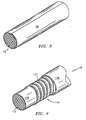
- FIG. 2 is an elevational side view of a stranded cable spiral-wrapped with a polyimide film or tape prior to undergoing a heat-sealing operation;
- FIG. 3 is an elevational side view of a stranded cable axially-wrapped with a polyimide film or tape prior to undergoing a heat-sealing operation;
- FIG. 4 is an elevational side view of a stranded cable insulated with a more preferred embodiment of the multi-layer insulation system of the present invention, having middle and outer insulating layers cut away for purposes of illustration.
- the multi-layer insulation system of the present invention possesses or demonstrates a combination of characteristics or properties not found in conventional insulating materials. This unique combination of desirable properties make the inventive insulated conductor most valuable in applications such as aircraft, missiles, satellites, etc.
- the high degree of high temperature adhesive bond strength demonstrated by the inner layer of a preferred embodiment of the present invention has been found to be particularly surprising.
- Insulated electrical conductor 10 basically comprises an electrical conductor 12, which is insulated with a multi-layer insulation system 14 comprising:
- the electrical conductor 12 of the present invention may take various forms (e.g., metal wire, stranded cable), and may be prepared using any suitable conductive material including copper, copper alloys, nickel, nickel-clad copper, nickel-plated copper, tin, silver, and silver-plated copper.
- the electrical conductor is in the form of a stranded cable, and is prepared using copper or nickel-plated copper.
- the polyimide film is a polyimide copolymer film derived from the reaction of an aromatic tetracarboxylic acid dianhydride component comprising from 0 to 95 mole %, preferably from 10 to 95 mole %, of 3,3',4,4'-biphenyltetracarboxylic dianhydride and from 5 to 100 mole %, preferably from 5 to 90 mole %, of pyromellitic dianhydride, and an aromatic diamine component comprising from 25 to 99 mole %, preferably from 40 to 98 mole %, of p-phenylene diamine and from 1 to 75 mole %, preferably from 2 to 60 mole %, of a diaminodiphenyl ether such as 4,4'-diaminodiphenyl ether, 3,3'-diamino
- Polyimide films suitable for use in inner layer 16 of the present invention are films having a sealable component (i.e ., a heat-sealable adhesive) coated or laminated on/to at least one surface. It is noted that such films are typically purchased with at least one surface coated with a heat-sealable adhesive, where the coating or lamination of such films constitutes a highly' specialized area of practice undertaken by only a limited number of companies.
- a sealable component i.e ., a heat-sealable adhesive
- Heat-sealable adhesives which may be used in the present invention include perfluoropolymer, crosslinkable fluoropolymer, and polyimide adhesives.
- Perfluoropolymer adhesives suitable for use in the present invention, include PTFE, FEP, PFA, and copolymers of tetrafluoroethylene and perfluoromethylvinylether (MFA) adhesives, while suitable crosslinkable fluoropolymer adhesives include ETFE and chlorotrifluoroethylene (CTFE) copolymer and terpolymer adhesives which contain minor amounts of one or more fluorinated comonomers (e.g., HFP, HFIB, PFBE, VDF and VF).
- fluorinated comonomers e.g., HFP, HFIB, PFBE, VDF and VF.
- Polyimide adhesives suitable for use in the present invention, include thermoplastic polyimide adhesives, which soften and become fluid at or above 200°C.
- Preferred heat-sealable films are polyimide films coated or laminated with a heat-sealable polyimide adhesive. Such materials are available from E.I. DuPont de Nemours and Company ("DuPont"), Wilmington, DE, under the trade designation KAPTON HKJ, KAPTON EKJ, and ELJ heat-sealable polyimide films.
- the heat-sealable films are preferably applied to an electrical conductor 12 in tape form, by either spirally or axially wrapping the tape about the conductor 12.
- the tape preferably has a width ranging from about 0.30 to about 0.95 centimeters (cm), and a thickness ranging from about 0.01 to about 0.04 millimeters (mm).
- the tape 20 is preferably wrapped so as to achieve a degree of overlap ranging from about 10 to about 70 %.
- the tape 20 preferably has a width ranging from about 0.15 to about 0.50 cm, and a thickness ranging from about 0.01 to about 0.04 mm.
- the tape 20 preferably has a width of from about 115 to about 150 % of the conductor circumference, and a thickness ranging from about 0.01 to about 0.04 mm.
- FIG. 3 which depicts the conductor 12 axially-wrapped with the polyimide tape 20 prior to undergoing a heat-sealing operation, the tape 20 is preferably wrapped so as to achieve a degree of overlap ranging from about 15 to about 50 %.
- the resulting assembly is heated to a temperature ranging from about 240 to about 350 °C, preferably from about 260 to about 280 °C.
- the purpose of the heating operation is to bond or fuse the overlapping regions of the polyimide tape 20, thereby forming an effective seal against moisture along the length of the conductor 12. As a result, the electrical integrity of the conductor 12 will be preserved.
- the thickness of the inner layer 16 of the insulated electrical conductor 10 of the present invention preferably ranges from about 0.01 to about 0.08 mm, and more preferably ranges from about 0.02 to about 0.05 mm.
- Inner layer 16 demonstrates a high temperature (i.e., 150°C) adhesive bond strength ranging from about 100 to about 250 grams per inch-width (gm/inch-width).
- a high temperature (i.e., 150°C) adhesive bond strength ranging from about 100 to about 250 grams per inch-width (gm/inch-width).
- a high temperature (i . e ., 150°C) adhesive bond strength of greater than 1000 gm/inch-width, preferably greater than 1500 gm/inch-width.
- Such adhesive bond strengths are considerably higher than those demonstrated by prior art heat-sealed wire insulations.
- High temperature adhesive bond strength is measured in accordance with ASTM# 1876-00 - Standard Test Method for Peel Resistance of Adhesives (T-Peel Test).
- Fluoropolymers which may advantageously be utilized in the outer layer 18 of the insulated electrical conductor 10 of the present invention include, for example, copolymers and terpolymers of ethylene-tetrafluoroethylene (ETFE), and mixtures thereof.
- ETFE ethylene-tetrafluoroethylene
- extruded fluoropolymer outer layers change color as a result of thermal aging.
- polyimides demonstrate greater thermal stability than fluoropolymers
- the noted color change in the outer layer can serve as an early warning signal that the insulated electrical conductor will need to be replaced. This feature is extremely valuable in aircraft wire and cable applications.
- the fluoropolymer of outer layer 18 is an ETFE copolymer which comprises 35 to 60 mole % (preferably 40 to 50 mole %) of units derived from ethylene, 35 to 60 mole % (preferably 50 to 55 mole %) of units derived from tetrafluoroethylene and up to 10 mole % (preferably 2 mole %) of units derived from one or more fluorinated comonomers (e.g., HFP, HFIB, PFBE, VDF and VF).
- fluorinated comonomers e.g., HFP, HFIB, PFBE, VDF and VF.
- Such copolymers are available from DuPont under the trade designation TEFZEL HT 200, and from Daikin America, Inc. ("Daikin"), Orangeburg, NY, under the trade designation NEOFLON EP-541.
- the fluoropolymer(s) preferably contains (as extruded) from about 4 to about 16 % by weight of a crosslinking agent.
- Preferred crosslinking agents are radiation crosslinking agents that contain multiple carbon-carbon double bonds.
- crosslinking agents containing at least two allyl groups and more preferably, three or four allyl groups, are employed.
- Particularly preferred crosslinking agents are triallyl isocyanurate (TAIC), triallylcyanurate (TAC) and trimethallylisocyanurate (TMAIC).
- the fluoropolymer(s) contains a photosensitive substance (e.g., titanium dioxide), which renders the outer layer 18 receptive to laser marking.
- a photosensitive substance e.g., titanium dioxide
- laser marking is intended to mean a method of marking an insulated conductor using an intense source of ultraviolet or visible radiation, preferably a laser source. In accordance with this method, exposure of the fluoropolymer outer layer 18 to such intense radiation will result in a darkening where the radiation was incident. By controlling the pattern of incidence, marks such as letters and numbers can be formed.
- the fluoropolymer(s) contains from about 1 to about 4 % by weight, of titanium dioxide.
- the fluoropolymer(s) may advantageously contain other additives such as pigments (e.g., titanium oxide), lubricants (e.g., PTFE powder), antioxidants, stabilizers, flame retardants (e.g., antimony oxide), fibers, mineral fibers, dyes, plasticizers and the like.
- pigments e.g., titanium oxide
- lubricants e.g., PTFE powder
- antioxidants e.g., stabilizers
- flame retardants e.g., antimony oxide
- fibers e.g., mineral fibers, dyes, plasticizers and the like.
- some such additives may have an adverse effect on the desirable properties of the insulated electrical conductor of the present invention.
- the components of the outer layer may be blended together by any conventional process until a uniform mix is obtained.
- a twinscrew extruder is used for compounding.
- the outer layer 18 is preferably formed by melt-extrusion, and then crosslinked using either known techniques, which include beta and gamma radiation crosslinking methods, or "skin irradiation" techniques. "Skin irradiation” techniques are described in more detail below.
- the thickness of the outer layer 18 of the insulated electrical conductor 10 of the present invention preferably ranges from about 0.05 to about 0.25 mm, and more preferably ranges from about 0.10 to about 0.13 mm.
- insulated electrical conductor 110 demonstrates improved flexibility, and comprises an electrical conductor 112, which is insulated with a multi-layer insulation system 114 comprising:
- Fluoropolymers which may advantageously be utilized in the inner layer 116 of the insulated electrical conductor 110 of the present invention include, for example, MFA, PFA, PTFE, ethylene-chlorotrifluoroethylene (ECTFE) copolymers, ethylene-tetrafluoroethylene (ETFE) copolymers, polyvinylidene fluoride (PVDF), tetrafluoroethylene-hexafluoropropylene-vinylidene fluoride (THV), polyvinylfluoride (PVF) resins, and mixtures thereof.
- MFA MFA
- PFA ethylene-chlorotrifluoroethylene
- ETFE ethylene-tetrafluoroethylene
- PVDF polyvinylidene fluoride
- TSV tetrafluoroethylene-hexafluoropropylene-vinylidene fluoride
- PVF polyvinylfluoride
- inner layer 116 is extruded and the fluoropolymer comprises a copolymer or terpolymer of ETFE.
- the polymer is an ETFE terpolymer that has been compounded with a TAIC crosslinking agent.
- TAIC crosslinking agent such polymers are available from DuPont and Daikin, under the product designations TEFZEL HT200 fluoropolymer resin and NEOFLON EP-541 fluoropolymer resin, respectively.
- inner layer 116 is extruded and crosslinked and the extruded fluoropolymer material of inner layer 116 is substantially the same as the material used to prepare outer layer 118, but contains less crosslinking agent.
- inner layer 116 is wrapped and the fluoropolymer is PTFE tape.
- the PTFE is in the form of a skived tape, with such tapes being available from Goodrich Corporation, Four Coliseum Centre, 2730 West Tyvola Road, Charlotte, NC 28217-4578, under the product designation PTFE Skived Tapes.
- the fluoropolymer film inner layer 116 may be a heat-sealed or a non-heat-sealed fluoropolymer film inner layer. It is noted that wrapped fluoropolymer tapes or films will fuse or bond to themselves in overlapping regions at temperatures at or above the melting point of the fluoropolymer, thereby obviating the need to employ a heat-sealable adhesive with such films.
- the polyimide film of middle layer 117 is preferably applied to inner layer 116 in tape form, by spirally wrapping the tape about inner layer 116, so as to achieve a degree of overlap ranging from about 10 to about 70 %.
- the polyimide film of middle layer 117 does not employ a heat-sealable adhesive and is not heat-sealed.
- the polyimide film employs a heat-sealable adhesive and is substantially uniformly sealed to itself in over-lapping regions along the length of inner layer 116.
- inner layer 116 is formed using a fluoropolymer tape and the fluoropolymer tape is heated together with the coated polyimide film, but is not sealed.
- Preferred non-heat-sealable polyimide films have a thickness ranging from about 0.01 to about 0.04 mm, and are available from DuPont, under the trade designation KAPTON H and KAPTON E polyimide films. Preferred heat-sealable polyimide films are the same as those noted above for inner layer 16.
- the preferred insulated electrical conductor 110 described above which employs a non-heat-sealed polyimide film middle layer, demonstrates a degree of flex which is substantially greater than prior art wire constructions.
- the degree of flex or wire flexibility is measured by: selecting a 0.9 meter section of insulated wire ( i.e.
- an insulated stranded nickel plated copper conductor (20 American Wire Gage (AWG), 19 Strand, nickel plated copper) measuring 0.95 mm in diameter), which is substantially free of kinks and bends; attaching a ring connector to each end of the conductor; attaching a 100 gram weight to each ring connector; carefully suspending the insulated wire on a stationary mandrel having a diameter measuring 0.48 cm; waiting one minute; and measuring the width between parallel insulated wire segments at three different points along the length of the wire.
- the degree of flex or wire flexibility is an average of the three width measurements.
- insulated electrical conductor 110 comprises an electrical conductor 112, which is insulated with a multi-layer insulation system 114 comprising: (1) an extruded, crosslinked ETFE inner layer 116; (2) a non-heat-sealed polyimide film middle layer 117; and (3) an extruded, crosslinked ETFE outer layer 118.
- insulated electrical conductor 110 comprises an electrical conductor 112, which is insulated with a multi-layer insulation system 114 comprising: (1) a non-heat-sealed PTFE inner layer 116; (2) a heat-sealed polyimide film middle layer 117; and (3) an extruded, crosslinked ETFE outer layer 118.
- the insulated conductor 10, 110 may comprise a single wire covered with the multi-layer insulation system 14, 114 of the present invention, or may comprise a plurality of bunched, twisted, or bundled wires, with each wire separately covered with the multi-layer insulation system 14, 114.
- the insulated conductor 10, 110 may also comprise a plurality of single or dual layer insulated wires which are coated with the polyimide or fluoropolymer inner layer 16, 116 and optionally, with the polyimide film middle layer 117.
- the plurality of single or dual layer insulated wires are covered with a sheath consisting of the crosslinked fluoropolymer outer layer 18, 118.
- the process for preparing the insulated electrical conductor 10, 110 of the present invention basically comprises:
- Insulated electrical conductors 10, 110 that do not employ perfluoropolymers are preferably subjected to an irradiation step to effect crosslinking in the fluoropolymer outer layer 18, 118.
- the dosage of ionizing radiation e.g., accelerated electrons or gamma rays
- the dosage of ionizing radiation (e.g., accelerated electrons or gamma rays) employed in the irradiation step is below 50 megarads (Mrads), more preferably, between 5 and 25 Mrads and, most preferably, between 15 and 25 Mrads, while applied voltages range from about 0.25 to about 3.0 mega volts (MV), and preferably range from about 0.5 to about 1.0 MV.
- the irradiation step is preferably carried out at ambient temperature.
- Insulated electrical conductors 10, 110 which employ an inner layer or sealable component comprising a perfluoropolymer are subjected to a so-called "skin irradiation" process to effect crosslinking in the fluoropolymer outer layer 18, 118.
- the subject process employs ionizing radiation in the form of accelerated electrons, and basically comprises using an accelerated voltage such that the maximum attained distance of accelerated charged particles is less than or equal to the thickness of the outer layer 18, 118. More specifically, with an applied voltage of 120 KV, most electrons will penetrate outer layer 18,118 to a maximum depth of approximately 0.13 mm.
- JP 4-52570 Such a technique or process is briefly described in JP 4-52570 in regard to automotive low voltage wire coated with e.g. a soft vinyl chloride resin.
- JP 4-52570 is incorporated herein by reference.
- the dosage of ionizing radiation (i . e ., accelerated electrons) employed in the irradiation step is below 60 Mrads, more preferably, between 20 and 50 Mrads and, most preferably, between 30 and 40 Mrads, while applied voltages range from about 50 to about 120 kilo volts (KV), and preferably range from about 100 to about 120 KV.
- the "skin irradiation" technique or process is preferably carried out at ambient temperature.
- the present inventors have discovered that by exposing "skin irradiated" insulated electrical conductor 10, 110 to elevated temperatures ranging from about 150 to about 220 °C, accumulated electrons may be more effectively drained off without damaging the insulation.
- the insulated electrical conductor 10, 110 of the present invention is lightweight, and may be used in environments where temperatures may exceed 230°C.
- the inventive conductor 10, 110 demonstrates mechanical durability and resistance to hydrolysis.
- insulated conductor 10, 110 weighs from about 1.9 to about 2.0 kilograms (kg) per 305 meters (m), which serves to satisfy the maximum weight limits set forth in the following Military Specifications - M22759/92-20, M22759/86-20, M22759/32-20, and M22759/34-20.
- the 230°C temperature rating of insulated electrical conductor 10, 110 was determined in accordance with Military Specification MIL-DTL-22759/87A - Accelerated Aging Test. This test, which requires aging wire samples for 500 hours in an air-circulating oven maintained at a temperature of 290°C, was modified to the extent that the oven temperature was reduced to 260°C.
- the multi-layer insulation system and insulated electrical conductor 10, 100 of the present invention demonstrate other desirable properties including excellent resistance to flame, the ability to be marked using ultraviolet or visible radiation, electrical resistance, humidity resistance, low smoke generation, notch propagation resistance, weathering resistance, wet and dry arc track resistance, and resistance to common solvents and other fluids used in the aircraft industry.
- CONDUCTOR a stranded nickel plated copper conductor (20 American Wire Gage (AWG), 19 Strand, nickel plated copper) measuring 0.95 mm in diameter.
- POLYIMIDE FILM I heat-sealable polyimide film coated or laminated on both sides with a heat-activated, high temperature polyimide adhesive, marketed under the trade designation KAPTON HKJ heat-sealable polyimide film, by DuPont.
- POLYIMIDE FILM II heat-sealable polyimide film coated or laminated on both sides with a heat-activated, high temperature polyimide adhesive, marketed under the trade designation KAPTON EKJ heat-sealable polyimide film, by DuPont.
- POLYIMIDE FILM III heat-sealable polyimide film coated or laminated on both sides with a heat-activated, medium temperature polyimide adhesive, marketed under the trade designation KAPTON ELJ heat-sealable polyimide film, by DuPont.
- POLYIMIDE FILM IV heat-sealable polyimide film coated or laminated on both sides with a heat-activated perfluoropolymer adhesive, marketed under the trade designation KAPTON XP heat-sealable polyimide film, by DuPont.
- POLYIMIDE FILM V heat-sealable polyimide film coated or laminated on both sides with a heat-activated perfluoropolymer adhesive, marketed under the trade designation OASIS TWT561 heat-sealable polyimide film, by DuPont.
- ETFE a copolymer comprising 35 to 60 mole % of ethylene; 60 to 35 mole % of tetrafluoroethylene; and up to 10 mole % of a fluorinated termonomer, marketed under the trade designation TEFZEL HT 200 fluoropolymer resin, by DuPont. Melting point of fluoropolymer resin is approximately 270°C.
- ETFE(I) a copolymer comprising 30 to 50 mole % of ethylene; 70 to 50 mole % of tetrafluoroethylene; and up to 10 mole % of a fluorinated termonomer, marketed under the trade designation TEFZEL HT 2127 fluoropolymer resin, by DuPont.
- PTFE a skived polytetrafluoroethylene film, marketed under the trade designation TEFLON TFE fluoropolymer resin, by DuPont.
- TAIC a triallyl isocyanurate crosslinking agent, marketed under the designation TAIC triallyl isocyanurate, by Nippon Kasei Chemical Co., Ltd., Tokyo, Japan.
- TiO 2 titanium dioxide pigment in powder form ( ⁇ 96 % in purity), marketed under the trade designation TIPURE titanium dioxide pigment, by DuPont.
- the spiral-wrapped CONDUCTOR was then heated in a continuous process to a temperature in excess of 300°C for approximately 5 seconds to heat-seal the overlapping portions of the POLYIMIDE FILM I strip, and was then allowed to cool.
- the thickness of the heat-sealed, spiral-wrapped POLYIMIDE FILM I inner layer was 0.05 mm.
- ETFE was compounded with 8 % by wt. TAIC and 2 % by wt. TiO 2 and was then extruded over the POLYIMIDE FILM I inner layer using a single-screw extruder having four heating zones which were set at 200°, 240°, 275°, and 290°C, respectively.
- the thickness of the extruded ETFE layer was 0.13 mm.
- Test samples were then irradiated using electron-beam radiation, with air-cooling.
- Total beam dosages were 10, 15, 20, or 30 megarads, while applied voltages were either 120 KV, 150 KV, or 0.5 MEV.
- Example 2 Four test samples of the wire construction labeled Example 2, ten test samples of Example 3, and six test samples of Example 4, were prepared substantially in accordance with the method identified above for Example 1, except that test samples for each Example were prepared using a different polyimide film. As above, total beam dosages were 10, 15, 20, or 30 megarads, while applied voltages were either 120 KV, 150 KV, or 0.5 MEV.
- Example 5 One thousand feet of the wire construction labeled Example 5 were repared substantially in accordance with the method identified above for Examples 1A to 1E, except that total beam dosage was 18 megarads, while applied voltages were 0.5 mega electron volts.
- the spiral-wrapped CONDUCTOR was then heated in a continuous process to a temperature in excess of 300 °C for approximately 5 seconds to heat-seal the overlapping portions of the POLYIMIDE FILM layer, and was then allowed to cool.
- the thickness of the inner and middle layers was 0.076 mm (Examples 6 and 7) and 0.061 mm (Examples 8 and 9).
- ETFE or ETFE(I) was compounded with 8 % by wt. TAIC and 2 % by wt. TiO 2 and was then extruded over the POLYIMIDE FILM middle layer using a single-screw extruder having four heating zones which were set at 200°, 240°, 275°, and 290°C, respectively.
- the thickness of the extruded ETFE or ETFE(I) layers was 0.13 mm (Examples 6 and 7) and 0.14 mm (Examples 8 and 9).
- C-1 was prepared substantially in accordance with the method identified above for Example 1, except that 0.06 mm thick PTFE tape was spiral-wrapped, with a 53 % overlap, over a spiral-wrapped POLYIMIDE FILM IV inner layer prior to heat-sealing. The resulting wire construction was then exposed to a temperature in excess of 330°C to effect heat-sealing in both layers.
- C-2 was prepared by compounding ETFE with 1.5 % by wt. TAIC, and then by extruding the compounded material over the CONDUCTOR using a single-screw extruder, as described above.
- Total beam dosage was 30 megarads, with an applied voltage of 0.5 MEV.
- Test Methods Accelerated Aging or Shrinkage Resistance (P,F): Boeing BSS 7324, paragraph no. 7.1a, pp. 12 to 14, conducted at 280 °C.
- Current Overload Capacity Boeing BSS 7324, paragraph no. 7.16, pp. 48 to 50, conducted at room temperature.
- the insulated wire test samples were evaluated for current overload capacity by removing 13mm of insulation from wire samples measuring 1.5m in length. The samples were then suspended horizontally in a test set-up with no visible sag. Then, 33 amperes (amps) of current was applied to each test sample for a period of 5 minutes and the samples cooled to room temperature. Each test sample was visually inspected during current application and after the samples were returned to room temperature.
- the test was performed at room temperature (23°C), at 150°C, at 200°C, and at 260°C, to evaluate the effect of the elevated temperature on insulation performance.
- the standard cutting edge used was stainless steel and had a radius of 0.406 mm.
- a 600 mm (in length) test sample was clamped in place between a blade and a flat plate within an INSTRON compression tester, and the ends of the conductor connected to an 18 VDC electrical circuit.
- the cutting edge of the blade was oriented perpendicularly to the axis of the sample.
- the cutting edge was then forced through the insulation at a constant rate of 1.27 mm per minute until contact with the conductor occurred.
- a detection circuit sensed contact of the cutting edge with the conductor and recorded the maximum force encountered during the test.
- the insulation from five of the seven pieces was stripped from the ends of each piece exposing about 5mm of conductor and the pieces designated "active wires.” The insulation from the remaining two wires was left intact and the pieces designated "passive wires.” The seven wire pieces were then bundled such that one active wire was located in the center of the bundle while the remaining six wire pieces surrounded the central active wire. The two passive wires were located side-by-side within the bundle. The seven-wire bundle was laced together at four locations so as to keep all seven wires tightly held together throughout the length of the bundle. The distance between the two central laces was about 2.5 cm, while the distance between the central two laces and the outer two laces was about 1,2S cm.
- the wire bundle was then placed in a jig similar to that shown in the Boeing BSS 7324 Specification.
- the two passive wires were located at the bottom of the jig, while the stripped wires were individually connected to an electrical circuit. More specifically, the five active wires were connected to a three phase 400 Hz power source. Then, a knife blade with a 250 gm load was placed on top of the wire bundle perpendicular to each wire and the blade movement initiated. The blade moved back and forth at a speed of 0.75 cycles/second. When the top two wires were shorted out, the system was de-energized. Each wire was exposed to a 1000 volt wet dielectric withstand test to check whether the remaining insulation could withstand such voltage.
- the inner insulation layer was deemed “continuously peelable” if the entire width of the tape could be continuously peeled from at least five revolutions of the wire without tearing.
- test samples were then allowed to age in the salt solution for from 672 to >10,000 hours at 70°C ⁇ 2°C. Starting at 672 hours, the test samples were visually inspected and then periodically subjected to the Withstand Voltage Test as described below. The Hydrolysis Test was deemed “passed” if the sample, upon being subjected to the Withstand Voltage Test, did not demonstrate any electrical breakdown.
- test voltage 2.5 kV (rms) was then applied through an electrode between the conductor and the solution for five (5) minutes.
- Test samples were tested for life cycle by aging the samples and then by subjecting the aged samples to the Withstand Voltage Test noted above. The samples were aged by separately fixing the samples on a mandrel having a one-half inch diameter and then placing the mandrel and test samples in an air circulation oven set at 30°C above the intended temperature rating for the product, for a period of 500 hours.
- Laser Markability Boeing BSS 7324, paragraph no. 7.36, pp. 82 to 83, conducted at room temperature. Test conducted by Spectrum Technologies PLC, Western Avenue, Bridgend CF31 3RT, UK, using a CMS II Contrast Meter.
- CAT-3 in accordance with Military Specification MIL-T-5438 and that was capable of exerting a force on the sample while drawing the abrasion tape under the sample at a fixed rate.
- 150J garnet sandpaper (with 10mm conductive strips perpendicular to the edge of the sandpaper spaced a maximum of every 75mm) was drawn under the sample at a rate of 1500 ⁇ 75mm/min while a total force of 2.16 ⁇ 0.05 N was exerted on the test sample.
- the sandpaper approached and exited each test sample from below at an angle of 29 ⁇ 2° to the axis of the test sample and was supported by a rod 6.9mm in diameter.
- Test samples were tested for wet arc propagation resistance by preparing seven test samples measuring 35cm in length from a 3m long insulated wire sample. Five of the seven wire segments were stripped at both ends exposing about 5mm of conductor. These stripped wire segments were designated “active wires.” The remaining two wire segments that were not stripped were called “passive wires.” The seven wire pieces were then bundled such that one active wire was located in the center of the bundle while the remaining six wire pieces surrounded the central active wire. The two passive wires were located side-by-side within the bundle. The seven-wire bundle was laced together at four locations so as to keep all seven wires tightly held together throughout the length of the bundle.
- the distance between the two central laces was about 2.5 cm, while the distance between the central two laces and the outer two laces was about 1.25 cm.
- Two wires located on top of the seven-wire bundle had slits measuring 0.5 to 1.0mm in width that were perpendicular to the wire axis. The slits were positioned 6mm apart.
- the stripped wires were connected to a three phase power source according to the scheme set forth in the Boeing BSS 73244 Specification.
- the wire bundle was energized and a 5% aqueous salt solution was dripped onto the wire bundle where the two exposed slits were located.
- the rate of application of the salt solution was 8 to 10 drops per minute. This condition was continued for 8 hours unless the bundle failed by tripping a circuit breaker.
- wire bundles were taken out. Each wire was initially exposed to a 1000 volt wet dielectric withstand test initially, then 2500 volts. When a wire withstood a 1000 volt wet dielectric withstand test, it passed the test. This test was deemed passed if: (1) a minimum of 64 wires passed the dielectric test; (2) three wires or less failed the dielectric test in any one bundle; and (3) actual damage to the wire was not more than 3 inches in any test bundle. Wire-to-wire abrasion resistance (cycles to failure, 6,150,000 cycles minimum): Boeing BSS 7324, paragraph no. 7.57, p. 108.
- Test samples were tested for wire-to-wire abrasion resistance in accordance with the following method.
- One wire test sample measuring approximately 28cm in length was crossed with another wire sample measuring approximately 40cm in length at the center of the shorter wire as shown in the Boeing BSS 7324 Specification.
- One end of one wire specimen was fixed on an upper plate while the other end of the same wire was fixed on a lower plate.
- One end of the other wire was fixed on the lower plate while the other end of the same wire was loaded with a 1.13 Kg weight.
- the upper and lower plates were 45mm apart.
- the lower plate moved back and forth with a 6.35mm double amplitude at 10 cycles per second.
- the fixed member of the wire was connected to a power source so that the cycle counter stopped when the two wire specimens made an electrical contact by wearing out the insulation layer. If the cycle count at the stopping point was greater than 6,150,000, the result was considered passing.
- Example 1A EXAMPLE TOTAL BEAM DOSAGE (Mrad) ELECTRON BEAM VOLTAGE (MV) LIFE CYCLE (P,F) ACCELERATED AGING (P,F) HYDROLYSIS RESISTANCE 1 (P,F) WET ARC PROPAGATION RESISTANCE (P,F) WIRE-TO-WIRE ABRASION (6,150,000cycles minimum) 1A 30 0.5 P P P P P 42,885,600 1 2000 hour requirement met, test continuing.
- the insulated conductor of the present invention may be used at temperatures of up to 230°C, and demonstrates a balance of properties including shrinkage resistance, mechanical durability, hydrolysis resistance, and wet arc propagation resistance.
- Example 1B, 2, and 3A in Table 3 the insulated conductor of the present invention demonstrated a resistance to sandpaper abrasion which was greatly improved over that demonstrated by the prior art wire construction Example C-1, which employed a PTFE outer layer.
- Examples 3B and 4A demonstrate that insulated conductors employing irradiation degradable perfluoropolymer adhesives may be successfully prepared using a "skin irradiation" technique which effects crosslinking of the outer layer using low electron beam voltages of less than or equal to 120KV. As shown in Examples 3C and 4B, exposing these samples to electron voltages of 150KV appears to degrade the adhesive resulting in a sample where the outer layer is continuously peelable along the length of the test sample.
- Examples 1C, 1D and 1E which employed a polyimide adhesive, were not easily peelable regardless of whether the sample was irradiated at 120, 150 or 500KV, which indicated that higher electron beam voltages do not serve to degrade the polyimide adhesive.
- the insulated conductors of the present invention demonstrate a balance of properties including mechanical durability and hydrolysis resistance. More specifically, Examples 5 to 7 demonstrated good hydrolysis resistance, with Examples 8 and 9 noted as currently being tested but expected to demonstrate the same level of resistance. With regard to sandpaper abrasion resistance, Examples 5 to 7 performed similar to Comparative Example C-2. Examples 8 to 9 showed a slight drop-off in this property, while Comparative Example C-1 performed poorly presumably due to the nature of the PTFE outer layer.
- the insulated conductors of the present invention demonstrated greatly improved cut-through resistance over Comparative Examples C-1 and C-2, at all of the temperatures tested, while Examples 5, 7 and 8 demonstrated remarkable levels of wire-to-wire abrasion resistance.
- Examples 6, 7 and 9 passed each test, while Example 5 passed a majority of the tests. Similar results were obtained for dry arc propagation resistance, with each Example passing all, or a majority of, the tests.
- Examples 8 and 9 both demonstrated improved laser markability over Comparative Example C-1, while all of the inventive insulated conductors successfully passed the industry standard for strippability, namely - a strip force of from 1 ⁇ 4 to 6 Ibs.
- Example 8 qualified for a temperature rating of 230°C.
- all of the test samples satisfied the requirements for threshold current overload capacity.
Landscapes
- Physics & Mathematics (AREA)
- Spectroscopy & Molecular Physics (AREA)
- Chemical & Material Sciences (AREA)
- Chemical Kinetics & Catalysis (AREA)
- Insulating Bodies (AREA)
- Laminated Bodies (AREA)
- Insulated Conductors (AREA)
- Processes Specially Adapted For Manufacturing Cables (AREA)
- Selective Calling Equipment (AREA)
- Inorganic Insulating Materials (AREA)
- Forklifts And Lifting Vehicles (AREA)
- Particle Accelerators (AREA)
Applications Claiming Priority (3)
| Application Number | Priority Date | Filing Date | Title |
|---|---|---|---|
| US28430201P | 2001-04-17 | 2001-04-17 | |
| US284302P | 2001-04-17 | ||
| PCT/US2002/012113 WO2002084674A2 (en) | 2001-04-17 | 2002-04-17 | A multi-layer insulation system for electrical conductors |
Publications (2)
| Publication Number | Publication Date |
|---|---|
| EP1380036A2 EP1380036A2 (en) | 2004-01-14 |
| EP1380036B1 true EP1380036B1 (en) | 2007-10-10 |
Family
ID=23089665
Family Applications (1)
| Application Number | Title | Priority Date | Filing Date |
|---|---|---|---|
| EP02731399A Expired - Lifetime EP1380036B1 (en) | 2001-04-17 | 2002-04-17 | A multi-layer insulation system for electrical conductors |
Country Status (10)
| Country | Link |
|---|---|
| US (1) | US6781063B2 (zh) |
| EP (1) | EP1380036B1 (zh) |
| JP (1) | JP2004533092A (zh) |
| CN (1) | CN1314054C (zh) |
| AT (1) | ATE375594T1 (zh) |
| AU (1) | AU2002303379A1 (zh) |
| BR (1) | BR0208995B1 (zh) |
| CA (1) | CA2444044C (zh) |
| DE (1) | DE60222873D1 (zh) |
| WO (1) | WO2002084674A2 (zh) |
Cited By (3)
| Publication number | Priority date | Publication date | Assignee | Title |
|---|---|---|---|---|
| WO2010098847A1 (en) * | 2009-02-27 | 2010-09-02 | Tyco Electronic Corporation | Multi-layer insulated conductor with crosslinked outer layer |
| EP2378612A1 (de) * | 2010-04-15 | 2011-10-19 | Hirschmann Automotive GmbH | Umspritzen eines Stanzgitters mit einem Kunststoff mit hoher Schwindungsrate |
| EP2988308A1 (en) * | 2014-08-19 | 2016-02-24 | Nexans | Arrangement and construction for airframe wires |
Families Citing this family (43)
| Publication number | Priority date | Publication date | Assignee | Title |
|---|---|---|---|---|
| US7485352B2 (en) * | 2003-07-04 | 2009-02-03 | Panasonic Corporation | Vacuum heat insulator and apparatus using the same |
| US20060049302A1 (en) * | 2004-08-31 | 2006-03-09 | Kennedy Dennis K | Apparatus and methods for structurally-integrated conductive conduits for rotor blades |
| CN100359610C (zh) * | 2004-10-29 | 2008-01-02 | 国光电子线股份有限公司 | 多层绝缘电线 |
| US7838765B2 (en) * | 2007-04-25 | 2010-11-23 | Linden Photonics, Inc. | Electrical conducting wire having liquid crystal polymer insulation |
| CN101308714B (zh) * | 2007-05-17 | 2010-11-10 | 上海长顺电梯电缆有限公司 | 一种低烟无卤阻燃电梯随行电缆的制备方法 |
| US7848604B2 (en) | 2007-08-31 | 2010-12-07 | Tensolite, Llc | Fiber-optic cable and method of manufacture |
| FR2921511B1 (fr) * | 2007-09-21 | 2010-03-12 | Nexans | Cable electrique resistant a la propagation d'arc electrique |
| US20090250243A1 (en) * | 2007-12-07 | 2009-10-08 | Wei Zhu | Arc resistant and smooth wire |
| US20100326696A1 (en) * | 2008-03-11 | 2010-12-30 | Amaresh Mahapatra | Liquid crystal polymer blends for use as metal wire insulation |
| US20090297858A1 (en) * | 2008-05-29 | 2009-12-03 | E. I. Du Pont De Nemours And Company | Multilayer insulation for wire, cable or other conductive materials |
| US20100219555A1 (en) * | 2009-02-27 | 2010-09-02 | Tyco Electronics Corporation | Method for extrusion of multi-layer coated elongate member |
| TW201108258A (en) * | 2009-04-24 | 2011-03-01 | Sumitomo Electric Industries | Electrical wire and method for manufacturing the same |
| US8816217B2 (en) | 2009-09-01 | 2014-08-26 | Kaneka North America Llc | Polyimides and fluoropolymer bonding layer with improved copper heat seal strength |
| MD4100C1 (ro) * | 2009-09-24 | 2011-09-30 | Технический университет Молдовы | Procedeu de confecţionare a unui rezistor din conductor |
| MD4092C1 (ro) * | 2009-09-24 | 2011-08-31 | Технический университет Молдовы | Instalaţie de turnare a microfirului |
| US9052486B2 (en) | 2010-10-21 | 2015-06-09 | Carlisle Interconnect Technologies, Inc. | Fiber optic cable and method of manufacture |
| US8822824B2 (en) | 2011-04-12 | 2014-09-02 | Prestolite Wire Llc | Methods of manufacturing wire, multi-layer wire pre-products and wires |
| US20120261160A1 (en) | 2011-04-13 | 2012-10-18 | Prestolite Wire Llc | Methods of manufacturing wire, wire pre-products and wires |
| CN102855975B (zh) * | 2011-06-30 | 2017-06-06 | 日立金属株式会社 | 绝缘电线及使用该绝缘电线的线圈 |
| FR2979032B1 (fr) * | 2011-08-09 | 2013-07-26 | Nexans | Cable electrique resistant aux decharges partielles |
| TWI529749B (zh) * | 2011-10-11 | 2016-04-11 | 東特塗料股份有限公司 | 多層覆皮之電絕緣電線 |
| CN102522167B (zh) * | 2011-12-30 | 2015-08-26 | 天津市华之阳特种线缆有限公司 | 聚酰亚胺卷绕套管及其加工方法 |
| CN102568680A (zh) * | 2012-03-14 | 2012-07-11 | 四川川东电缆有限责任公司 | 一种风能电缆及制造方法 |
| US9455069B2 (en) * | 2012-07-24 | 2016-09-27 | Schlumberger Technology Corporation | Power cable system |
| JP5975334B2 (ja) * | 2012-09-13 | 2016-08-23 | 日立金属株式会社 | 発泡樹脂成形体、発泡絶縁電線及びケーブル並びに発泡樹脂成形体の製造方法 |
| WO2014113321A1 (en) * | 2013-01-15 | 2014-07-24 | Harbour Industries LLC | High temperature wire insulation |
| FR3002682B1 (fr) * | 2013-02-26 | 2015-03-20 | Peugeot Citroen Automobiles Sa | Faisceau electrique constitue par au moins une serie de conducteurs electriques longitudinalement les uns a cote des autres dans une gaine d'isolation electrique |
| EP2790189B1 (fr) * | 2013-04-08 | 2016-02-03 | Nexans | Cable de transmission de données destiné a l'industrie aéronautique |
| CN103235246B (zh) * | 2013-05-08 | 2016-04-20 | 上海电缆研究所 | 航空导线耐电弧实验装置及其实验方法 |
| EP3006209B1 (en) | 2013-05-31 | 2022-12-21 | Kaneka Corporation | Insulated coating material and use of same |
| JP6390694B2 (ja) * | 2014-02-26 | 2018-09-19 | Agc株式会社 | 電線の製造方法、成形品の製造方法、及び改質フッ素樹脂を含む樹脂材料の製造方法 |
| JP5708846B1 (ja) * | 2014-02-26 | 2015-04-30 | 株式会社オートネットワーク技術研究所 | 撚り線導体および絶縁電線 |
| WO2016084662A1 (ja) | 2014-11-27 | 2016-06-02 | 株式会社カネカ | 耐摩耗性の優れる絶縁被覆材料 |
| CN107004474B (zh) | 2014-11-27 | 2019-11-29 | 株式会社钟化 | 耐磨耗性优越的绝缘包覆材料 |
| JP6455420B2 (ja) * | 2015-12-25 | 2019-01-23 | オムロン株式会社 | 電子機器およびその製造方法 |
| WO2017131013A1 (ja) * | 2016-01-29 | 2017-08-03 | 旭硝子株式会社 | 冷凍サイクル装置 |
| CN108780201A (zh) * | 2016-02-19 | 2018-11-09 | 通用线缆技术公司 | 激光可标记的线缆和用于制造其的系统 |
| DE102017207656B4 (de) * | 2017-01-31 | 2023-03-02 | Leoni Kabel Gmbh | Kabel und Verwendung desselben als medizinisches Kabel |
| FR3062748B1 (fr) * | 2017-02-03 | 2019-04-05 | Nexans | Cable electrique resistant aux decharges partielles |
| US20190351639A1 (en) * | 2017-11-20 | 2019-11-21 | Sumitomo Electric Fine Polymer, Inc. | Heat-resistant two-layer heat-shrinkable tube and method for covering object to be covered |
| JP2019215970A (ja) * | 2018-06-11 | 2019-12-19 | 古河電気工業株式会社 | ケーブル |
| CN108899113A (zh) * | 2018-07-02 | 2018-11-27 | 芜湖航天特种电缆厂股份有限公司 | 聚酰亚胺绝缘电缆及其制备方法 |
| CN110993194A (zh) * | 2019-12-27 | 2020-04-10 | 新华三技术有限公司合肥分公司 | 一种线缆及其生产工艺 |
Family Cites Families (30)
| Publication number | Priority date | Publication date | Assignee | Title |
|---|---|---|---|---|
| US3269862A (en) | 1964-10-22 | 1966-08-30 | Raychem Corp | Crosslinked polyvinylidene fluoride over a crosslinked polyolefin |
| US3422215A (en) | 1967-02-16 | 1969-01-14 | Westinghouse Electric Corp | Insulated cable |
| US3408453A (en) | 1967-04-04 | 1968-10-29 | Cerro Corp | Polyimide covered conductor |
| US3488537A (en) | 1967-04-04 | 1970-01-06 | Gen Electric | Dynamoelectric machine having fluorocarbon plastic film insulation and method of making the same |
| DE2053960A1 (de) | 1970-11-03 | 1972-05-10 | Kabel Metallwerke Ghh | Verfahren zur Herstellung einer gefärbten, temperaturbeständigen, mechanisch festen elektrischen Leitung |
| US3763222A (en) | 1972-04-11 | 1973-10-02 | Itt | Esters of phenyl indan |
| US4031167A (en) | 1973-10-01 | 1977-06-21 | International Telephone And Telegraph Corporation | Crosslinking fluorocarbon compositions using polyallylic esters of polycarboxylic acids |
| US3911192A (en) | 1973-10-01 | 1975-10-07 | Itt | Coated wire products |
| US3852518A (en) | 1973-11-29 | 1974-12-03 | Gen Cable Corp | Irradiation cross-linked composite low density/high density polyethylene insulated 600 volt power cables |
| US3894118A (en) | 1974-01-21 | 1975-07-08 | Itt | Crosslinking agents for fluorocarbon polymers |
| US3970770A (en) | 1974-11-29 | 1976-07-20 | International Telephone And Telegraph Corporation | Wire coated with fluorocarbon polymers cross-linked with dialyl ester of 4,4'-dicarboxydiphenyl ester |
| US3995091A (en) | 1974-11-29 | 1976-11-30 | International Telephone And Telegraph Corporation | Wire coated with a fluorocarbon polymer cross-linked with esters of sulfonyl dibenzoic acid |
| US4155823A (en) | 1976-10-12 | 1979-05-22 | Raychem Corporation | Shaped article from crosslinked fluorocarbon polymer and process therefor |
| US4353961A (en) | 1977-09-14 | 1982-10-12 | Raychem Corporation | Shaped article from crosslinked fluorocarbon polymer |
| US4184001A (en) | 1978-04-19 | 1980-01-15 | Haveg Industries, Inc. | Multi layer insulation system for conductors comprising a fluorinated copolymer layer which is radiation cross-linked |
| US4310597A (en) | 1978-07-10 | 1982-01-12 | Northern Telecom Limited | Low voltage electrical wire |
| DE2965436D1 (en) | 1978-08-02 | 1983-07-07 | Bicc Plc | Manufacture of extruded products |
| US4628003A (en) | 1981-08-07 | 1986-12-09 | Morton Katz | High temperature heat seal film |
| US4401845A (en) | 1981-08-26 | 1983-08-30 | Pennwalt Corporation | Low smoke and flame spread cable construction |
| US4430385A (en) | 1982-02-18 | 1984-02-07 | Western Electric Company, Inc. | Compositely insulated conductor having a layer of irradiation cross-linked polymeric plastic material |
| DE3214447C2 (de) | 1982-04-20 | 1994-05-11 | Eilentropp Hew Kabel | Ungesintertes Wickelband des Polytetrafluorethylen |
| US5059483A (en) | 1985-10-11 | 1991-10-22 | Raychem Corporation | An electrical conductor insulated with meit-processed, cross-linked fluorocarbon polymers |
| JPS6358709A (ja) * | 1986-08-28 | 1988-03-14 | カ−リスル コ−ポレ−シヨン | 多層耐高温絶縁体で絶縁された導体 |
| US4801501A (en) | 1986-08-28 | 1989-01-31 | Carlisle Corporation | Insulated conductor with multi-layer, high temperature insulation |
| JP3065341B2 (ja) | 1989-02-23 | 2000-07-17 | ケムファブ コーポレイション | 改良されたポリイミド及びフルオロポリマーを含むフィルム及びラミネート |
| JPH0760167B2 (ja) | 1990-06-21 | 1995-06-28 | 三菱電機株式会社 | インバータ主回路スイッチング素子の良否判定装置 |
| US5220133A (en) | 1992-02-27 | 1993-06-15 | Tensolite Company | Insulated conductor with arc propagation resistant properties and method of manufacture |
| CN1066817A (zh) | 1992-04-17 | 1992-12-09 | 上海焦化厂常熟绝缘材料联营厂 | 亚胺彩色氟薄膜 |
| US5399434A (en) | 1993-12-21 | 1995-03-21 | E. I. Du Pont De Nemours And Company | High temperature polyimide-fluoropolymer laminar structure |
| US5731088A (en) | 1996-06-04 | 1998-03-24 | E. I. Du Pont De Nemours And Company | Multilayer polyimide-fluoropolymer insulation having superior cut-through resistance |
-
2002
- 2002-04-17 EP EP02731399A patent/EP1380036B1/en not_active Expired - Lifetime
- 2002-04-17 AT AT02731399T patent/ATE375594T1/de not_active IP Right Cessation
- 2002-04-17 BR BRPI0208995-5A patent/BR0208995B1/pt not_active IP Right Cessation
- 2002-04-17 AU AU2002303379A patent/AU2002303379A1/en not_active Abandoned
- 2002-04-17 CN CNB028100522A patent/CN1314054C/zh not_active Expired - Fee Related
- 2002-04-17 DE DE60222873T patent/DE60222873D1/de not_active Expired - Lifetime
- 2002-04-17 WO PCT/US2002/012113 patent/WO2002084674A2/en active IP Right Grant
- 2002-04-17 US US10/124,896 patent/US6781063B2/en not_active Expired - Lifetime
- 2002-04-17 JP JP2002581532A patent/JP2004533092A/ja active Pending
- 2002-04-17 CA CA002444044A patent/CA2444044C/en not_active Expired - Fee Related
Cited By (3)
| Publication number | Priority date | Publication date | Assignee | Title |
|---|---|---|---|---|
| WO2010098847A1 (en) * | 2009-02-27 | 2010-09-02 | Tyco Electronic Corporation | Multi-layer insulated conductor with crosslinked outer layer |
| EP2378612A1 (de) * | 2010-04-15 | 2011-10-19 | Hirschmann Automotive GmbH | Umspritzen eines Stanzgitters mit einem Kunststoff mit hoher Schwindungsrate |
| EP2988308A1 (en) * | 2014-08-19 | 2016-02-24 | Nexans | Arrangement and construction for airframe wires |
Also Published As
| Publication number | Publication date |
|---|---|
| JP2004533092A (ja) | 2004-10-28 |
| DE60222873D1 (de) | 2007-11-22 |
| ATE375594T1 (de) | 2007-10-15 |
| CA2444044C (en) | 2008-04-15 |
| WO2002084674A3 (en) | 2003-04-24 |
| WO2002084674A2 (en) | 2002-10-24 |
| CN1509482A (zh) | 2004-06-30 |
| CN1314054C (zh) | 2007-05-02 |
| BR0208995B1 (pt) | 2011-09-20 |
| BR0208995A (pt) | 2004-04-27 |
| US20030062190A1 (en) | 2003-04-03 |
| EP1380036A2 (en) | 2004-01-14 |
| US6781063B2 (en) | 2004-08-24 |
| AU2002303379A1 (en) | 2002-10-28 |
| CA2444044A1 (en) | 2002-10-24 |
Similar Documents
| Publication | Publication Date | Title |
|---|---|---|
| EP1380036B1 (en) | A multi-layer insulation system for electrical conductors | |
| EP0811483B1 (en) | Multilayer polyimide-fluoropolymer insulation having superior cut-through resistance | |
| US20100218975A1 (en) | Multi-layer insulated conductor with crosslinked outer layer | |
| US7049522B2 (en) | Lightweight composite electrical conductors and cables incorporating same | |
| JP5454804B2 (ja) | 絶縁ワイヤ | |
| US8530746B2 (en) | Polyimides and fluoropolymer bonding layer with improved internal adhesive strength | |
| US3269862A (en) | Crosslinked polyvinylidene fluoride over a crosslinked polyolefin | |
| US6359230B1 (en) | Automotive-wire insulation | |
| JP2930883B2 (ja) | 層状膜構造体および絶縁ワイヤ | |
| US6087591A (en) | Insulated electrical conductors | |
| EP0953195A1 (en) | Insulated electrical conductors | |
| US20100218974A1 (en) | Multi-layer insulated conductor with crosslinked outer layer | |
| EP0211505A2 (en) | Electrically insulating tape | |
| KR20230004822A (ko) | 권선에 사용하기 위한 절연 도체, 그로부터 유래된 권선 및 상응하는 제조 방법 | |
| JP3444941B2 (ja) | 耐熱・耐放射線性ケーブルおよびこれを用いた高速増殖炉の炉内構造物検査装置 | |
| JP3121376B2 (ja) | ポリイミド積層体及び該積層体で絶縁されたケーブル | |
| JPH0676643A (ja) | 耐熱性電線 | |
| JP3285097B2 (ja) | 絶縁電線 | |
| WO2001018824A1 (en) | Dual layer system suitable for use as electrical insulation for wires and other conductors | |
| JPH0418644B2 (zh) | ||
| JPH05144328A (ja) | 耐放射線性電線 |
Legal Events
| Date | Code | Title | Description |
|---|---|---|---|
| PUAI | Public reference made under article 153(3) epc to a published international application that has entered the european phase |
Free format text: ORIGINAL CODE: 0009012 |
|
| 17P | Request for examination filed |
Effective date: 20031103 |
|
| AK | Designated contracting states |
Kind code of ref document: A2 Designated state(s): AT BE CH CY DE DK ES FI FR GB GR IE IT LI LU MC NL PT SE TR |
|
| AX | Request for extension of the european patent |
Extension state: AL LT LV MK RO SI |
|
| 17Q | First examination report despatched |
Effective date: 20040924 |
|
| 17Q | First examination report despatched |
Effective date: 20040924 |
|
| GRAP | Despatch of communication of intention to grant a patent |
Free format text: ORIGINAL CODE: EPIDOSNIGR1 |
|
| GRAS | Grant fee paid |
Free format text: ORIGINAL CODE: EPIDOSNIGR3 |
|
| GRAA | (expected) grant |
Free format text: ORIGINAL CODE: 0009210 |
|
| AK | Designated contracting states |
Kind code of ref document: B1 Designated state(s): AT BE CH CY DE DK ES FI FR GB GR IE IT LI LU MC NL PT SE TR |
|
| REG | Reference to a national code |
Ref country code: GB Ref legal event code: FG4D |
|
| REG | Reference to a national code |
Ref country code: CH Ref legal event code: EP |
|
| REG | Reference to a national code |
Ref country code: IE Ref legal event code: FG4D |
|
| REF | Corresponds to: |
Ref document number: 60222873 Country of ref document: DE Date of ref document: 20071122 Kind code of ref document: P |
|
| NLV1 | Nl: lapsed or annulled due to failure to fulfill the requirements of art. 29p and 29m of the patents act | ||
| PG25 | Lapsed in a contracting state [announced via postgrant information from national office to epo] |
Ref country code: SE Free format text: LAPSE BECAUSE OF FAILURE TO SUBMIT A TRANSLATION OF THE DESCRIPTION OR TO PAY THE FEE WITHIN THE PRESCRIBED TIME-LIMIT Effective date: 20080110 Ref country code: ES Free format text: LAPSE BECAUSE OF FAILURE TO SUBMIT A TRANSLATION OF THE DESCRIPTION OR TO PAY THE FEE WITHIN THE PRESCRIBED TIME-LIMIT Effective date: 20080121 Ref country code: CH Free format text: LAPSE BECAUSE OF FAILURE TO SUBMIT A TRANSLATION OF THE DESCRIPTION OR TO PAY THE FEE WITHIN THE PRESCRIBED TIME-LIMIT Effective date: 20071010 Ref country code: LI Free format text: LAPSE BECAUSE OF FAILURE TO SUBMIT A TRANSLATION OF THE DESCRIPTION OR TO PAY THE FEE WITHIN THE PRESCRIBED TIME-LIMIT Effective date: 20071010 Ref country code: NL Free format text: LAPSE BECAUSE OF FAILURE TO SUBMIT A TRANSLATION OF THE DESCRIPTION OR TO PAY THE FEE WITHIN THE PRESCRIBED TIME-LIMIT Effective date: 20071010 |
|
| REG | Reference to a national code |
Ref country code: CH Ref legal event code: PL |
|
| PG25 | Lapsed in a contracting state [announced via postgrant information from national office to epo] |
Ref country code: PT Free format text: LAPSE BECAUSE OF FAILURE TO SUBMIT A TRANSLATION OF THE DESCRIPTION OR TO PAY THE FEE WITHIN THE PRESCRIBED TIME-LIMIT Effective date: 20080310 |
|
| PG25 | Lapsed in a contracting state [announced via postgrant information from national office to epo] |
Ref country code: AT Free format text: LAPSE BECAUSE OF FAILURE TO SUBMIT A TRANSLATION OF THE DESCRIPTION OR TO PAY THE FEE WITHIN THE PRESCRIBED TIME-LIMIT Effective date: 20071010 |
|
| ET | Fr: translation filed | ||
| PG25 | Lapsed in a contracting state [announced via postgrant information from national office to epo] |
Ref country code: DK Free format text: LAPSE BECAUSE OF FAILURE TO SUBMIT A TRANSLATION OF THE DESCRIPTION OR TO PAY THE FEE WITHIN THE PRESCRIBED TIME-LIMIT Effective date: 20071010 |
|
| PLBE | No opposition filed within time limit |
Free format text: ORIGINAL CODE: 0009261 |
|
| STAA | Information on the status of an ep patent application or granted ep patent |
Free format text: STATUS: NO OPPOSITION FILED WITHIN TIME LIMIT |
|
| PG25 | Lapsed in a contracting state [announced via postgrant information from national office to epo] |
Ref country code: BE Free format text: LAPSE BECAUSE OF FAILURE TO SUBMIT A TRANSLATION OF THE DESCRIPTION OR TO PAY THE FEE WITHIN THE PRESCRIBED TIME-LIMIT Effective date: 20071010 |
|
| 26N | No opposition filed |
Effective date: 20080711 |
|
| PG25 | Lapsed in a contracting state [announced via postgrant information from national office to epo] |
Ref country code: DE Free format text: LAPSE BECAUSE OF FAILURE TO SUBMIT A TRANSLATION OF THE DESCRIPTION OR TO PAY THE FEE WITHIN THE PRESCRIBED TIME-LIMIT Effective date: 20080111 |
|
| PG25 | Lapsed in a contracting state [announced via postgrant information from national office to epo] |
Ref country code: MC Free format text: LAPSE BECAUSE OF NON-PAYMENT OF DUE FEES Effective date: 20080430 |
|
| PG25 | Lapsed in a contracting state [announced via postgrant information from national office to epo] |
Ref country code: GR Free format text: LAPSE BECAUSE OF FAILURE TO SUBMIT A TRANSLATION OF THE DESCRIPTION OR TO PAY THE FEE WITHIN THE PRESCRIBED TIME-LIMIT Effective date: 20080111 |
|
| PG25 | Lapsed in a contracting state [announced via postgrant information from national office to epo] |
Ref country code: FI Free format text: LAPSE BECAUSE OF FAILURE TO SUBMIT A TRANSLATION OF THE DESCRIPTION OR TO PAY THE FEE WITHIN THE PRESCRIBED TIME-LIMIT Effective date: 20071010 |
|
| PG25 | Lapsed in a contracting state [announced via postgrant information from national office to epo] |
Ref country code: IE Free format text: LAPSE BECAUSE OF NON-PAYMENT OF DUE FEES Effective date: 20080417 |
|
| PG25 | Lapsed in a contracting state [announced via postgrant information from national office to epo] |
Ref country code: CY Free format text: LAPSE BECAUSE OF FAILURE TO SUBMIT A TRANSLATION OF THE DESCRIPTION OR TO PAY THE FEE WITHIN THE PRESCRIBED TIME-LIMIT Effective date: 20071010 |
|
| PG25 | Lapsed in a contracting state [announced via postgrant information from national office to epo] |
Ref country code: LU Free format text: LAPSE BECAUSE OF NON-PAYMENT OF DUE FEES Effective date: 20080417 |
|
| PG25 | Lapsed in a contracting state [announced via postgrant information from national office to epo] |
Ref country code: TR Free format text: LAPSE BECAUSE OF FAILURE TO SUBMIT A TRANSLATION OF THE DESCRIPTION OR TO PAY THE FEE WITHIN THE PRESCRIBED TIME-LIMIT Effective date: 20071010 |
|
| PG25 | Lapsed in a contracting state [announced via postgrant information from national office to epo] |
Ref country code: IT Free format text: LAPSE BECAUSE OF NON-PAYMENT OF DUE FEES Effective date: 20080430 |
|
| REG | Reference to a national code |
Ref country code: FR Ref legal event code: PLFP Year of fee payment: 14 |
|
| PGFP | Annual fee paid to national office [announced via postgrant information from national office to epo] |
Ref country code: GB Payment date: 20150427 Year of fee payment: 14 |
|
| PGFP | Annual fee paid to national office [announced via postgrant information from national office to epo] |
Ref country code: FR Payment date: 20150417 Year of fee payment: 14 |
|
| GBPC | Gb: european patent ceased through non-payment of renewal fee |
Effective date: 20160417 |
|
| REG | Reference to a national code |
Ref country code: FR Ref legal event code: ST Effective date: 20161230 |
|
| PG25 | Lapsed in a contracting state [announced via postgrant information from national office to epo] |
Ref country code: FR Free format text: LAPSE BECAUSE OF NON-PAYMENT OF DUE FEES Effective date: 20160502 Ref country code: GB Free format text: LAPSE BECAUSE OF NON-PAYMENT OF DUE FEES Effective date: 20160417 |