EP1378331A1 - Anschlagmaschine - Google Patents
Anschlagmaschine Download PDFInfo
- Publication number
- EP1378331A1 EP1378331A1 EP03009292A EP03009292A EP1378331A1 EP 1378331 A1 EP1378331 A1 EP 1378331A1 EP 03009292 A EP03009292 A EP 03009292A EP 03009292 A EP03009292 A EP 03009292A EP 1378331 A1 EP1378331 A1 EP 1378331A1
- Authority
- EP
- European Patent Office
- Prior art keywords
- profiles
- machine
- anvil
- stop
- hinge
- Prior art date
- Legal status (The legal status is an assumption and is not a legal conclusion. Google has not performed a legal analysis and makes no representation as to the accuracy of the status listed.)
- Granted
Links
- 229910052782 aluminium Inorganic materials 0.000 claims description 6
- XAGFODPZIPBFFR-UHFFFAOYSA-N aluminium Chemical compound [Al] XAGFODPZIPBFFR-UHFFFAOYSA-N 0.000 claims description 6
- 239000000463 material Substances 0.000 description 9
- 238000011161 development Methods 0.000 description 3
- 230000018109 developmental process Effects 0.000 description 3
- 238000003754 machining Methods 0.000 description 3
- 230000005540 biological transmission Effects 0.000 description 2
- 238000013461 design Methods 0.000 description 2
- 238000003780 insertion Methods 0.000 description 2
- 230000037431 insertion Effects 0.000 description 2
- 229910052751 metal Inorganic materials 0.000 description 2
- 239000002184 metal Substances 0.000 description 2
- 238000000034 method Methods 0.000 description 2
- 230000006978 adaptation Effects 0.000 description 1
- 230000015572 biosynthetic process Effects 0.000 description 1
- 239000011111 cardboard Substances 0.000 description 1
- 238000006243 chemical reaction Methods 0.000 description 1
- JEIPFZHSYJVQDO-UHFFFAOYSA-N iron(III) oxide Inorganic materials O=[Fe]O[Fe]=O JEIPFZHSYJVQDO-UHFFFAOYSA-N 0.000 description 1
- 239000010985 leather Substances 0.000 description 1
- 238000004519 manufacturing process Methods 0.000 description 1
- 229910001092 metal group alloy Inorganic materials 0.000 description 1
- 150000002739 metals Chemical class 0.000 description 1
- 239000004033 plastic Substances 0.000 description 1
- 238000012545 processing Methods 0.000 description 1
- 239000002023 wood Substances 0.000 description 1
Images


Classifications
-
- B—PERFORMING OPERATIONS; TRANSPORTING
- B27—WORKING OR PRESERVING WOOD OR SIMILAR MATERIAL; NAILING OR STAPLING MACHINES IN GENERAL
- B27F—DOVETAILED WORK; TENONS; SLOTTING MACHINES FOR WOOD OR SIMILAR MATERIAL; NAILING OR STAPLING MACHINES
- B27F7/00—Nailing or stapling; Nailed or stapled work
- B27F7/15—Machines for driving in nail- plates and spiked fittings
Definitions
- the invention relates to a striking machine for attachable to box-shaped containers Fittings with a frame that is divided and made of profiles as well as a mounting plate, a drive, an anvil and one Tool holder.
- box-shaped containers such as boxes, crates, suitcases or cases made of wood, cardboard, Leather, plastic or the like with one or more fittings, such as Fitting hinges, fasteners, handles or the like Stop machines of the type mentioned are used.
- the impact material to Example the upper and lower part of a box-shaped container is with the Place the item to be misted on the anvil that Is part of the machine, and actuated the striking machine, which causes the Fitting tool containing the hammer is moved towards the anvil like a hammer and all the points of the fitting are inserted into the material to be struck at the same time become.
- the stop tool is then within the stop cycle again moved away from the anvil, so that either the same tack material another place with another fitting or new stop material can be placed on the anvil.
- the invention seeks to remedy this.
- the invention is based on the object a striking machine for fittings attachable to box-shaped containers create that is suitable for small series, low acquisition and operating costs entails and requires little space.
- This task will solved according to the invention in that the mounting plate by a hinge the profiles can be swiveled.
- the striking machine is a striking machine for box-shaped containers Fittings created specifically for the needs of small series is adjusted.
- the striking machine has a low degree of automation on. This requires space and the weight of the machine extremely low. Due to the swiveling of the lifting machine there is also the possibility to attach hinges in the usual way from above; To lock fasteners from below after swiveling the device.
- the frame is made of aluminum. hereby the weight of the device is additionally reduced. At the same time, the danger of Reduced rust.
- a height adjustment is advantageously provided on the machine. This is easily adapting the device to the material thickness of the sling possible.
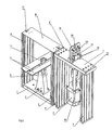
- the striking machine selected as an exemplary embodiment has a base plate 1 with which she gets up on the floor.
- the base plate 1 is made of aluminum.
- An anvil holder 2 is provided on the base body 1.
- the anvil holder 2 is preferably made of light metal.
- the anvil holder 2 tapers is wedge-like in the end view, starting from its base plate 1 facing foot part to its head part facing away from the base plate 1.
- To the An anvil 3 is attached to the head part of the anvil holder 2.
- the support tables 4 are guided tours 5 attached to the anvil holder 2 adjustable in height. Like especially the 4 can be seen, the support tables 4 are below aligned at an angle to the horizontal, so that the top and bottom of a box-shaped Container at an angle to each other during the striking process are aligned. So that the container does not diverge when struck, 4 adjustable side guides can be provided on the support tables serve as a holding device for the upper and lower part of the box-shaped container. The side guides can be adjusted in particular in the direction of movement of the container his. They can advantageously be spring-loaded.
- the striking machine has a frame that in the exemplary embodiment Aluminum profiles 6 and 9 and a mounting plate 7 is made.
- the profiles 6 form the part of the frame facing the floor, the profiles 9 the bottom part of the frame facing away.
- the profiles 6 of the frame are rectangular provided on the end faces of the base plate 1.
- the receiving plate 7 also referred to as the head plate can be.
- the receiving plate 7 is made of aluminum.
- the mounting plate 7 is pivotally arranged on the profiles. she for this purpose has a hinge 8, which in the exemplary embodiment on one of the two End faces of the receiving plate 7 and on one long side of one of the two profiles 6 is arranged.
- the selected arrangement and design of the hinge 8 there is a swivel range of 180 ° for the mounting plate 7.
- the mounting plate 7 is provided with a fastening unit 18.
- the profiles 9 are in the embodiment also in the form of aluminum profiles.
- a frame 10 is attached to the mounting plate 7, one - in the Pneumatic rule - drive 11 and a transmission part 12 holds. With the help of Drive 11 and the transmission part 12 becomes a tool holder 13 or a Tool like a plunger essentially perpendicular to the mounting plate 7 moves up and down.
- the tool holder 13 is designed such that it can accommodate both hinge and locking tools.
- a height adjustment 14 is provided, which enables adaptation to the material thickness of the fittings to be attached.
- the plunger in the head or mounting plate 7 serves to guide the plunger provided opening 15, which allows its passage in the direction of the anvil 3.
- the plate 16 is attached with the help of quick fasteners 17.
- the profiles 9 are in this Case with their ends facing away from the receiving plate 7 on the floor. They then act as supports.
- the length of the profiles 9 is advantageously chosen so that such a placement on the floor is possible to ensure a stable stand to ensure.
- the Support and cover plate 16 is for this purpose on the ends facing away from the floor the profile 6 fastened with the help of the quick fasteners 17.
- the fastening unit 18 takes in this Figure 2 case shown a bracket 19, which is provided with an anvil 20 is.
- a locking stop tool 21 is then in the tool holder 13 intended.
- the hinges are moved over an insertion rail (not shown), which is attached to the front of the hinge tool, one hinge pushing the next.
- the hinges are attached using a Magnets brought up to the pressure stamp.
- the hinge length is from Tool specified.
- the insertion rail and the pressure stamp are through Dowel pins held. This creates the possibility of the tool itself to be made from hardened material.
- the formation of the stop of the invention Machine enables both as a hinge stop and as Lock stop to be used.
- the striking machine according to the invention has a compact design. In the state shown in Figures 1, 3 and 4, it has a space requirement of about 0.5 m in width and about 0.2 m in depth; in the swung open state ( Figure 2) the width is about 1 m. The height of the striking machine is less than 1.5 m. The stop area is approx. 0.5 m. Among other things, it is suitable as Table machine.
- Weight of the striking machine according to the invention low; in the embodiment it is less than 40 kg. This is in connection with the small dimensions the striking machine created the possibility of pre-assembled the machine State to send by post or parcel service, which is a significant one Simplification in the area of shipping represents.
Landscapes
- Engineering & Computer Science (AREA)
- Mechanical Engineering (AREA)
- Life Sciences & Earth Sciences (AREA)
- Forests & Forestry (AREA)
- Sealing Of Jars (AREA)
- Bending Of Plates, Rods, And Pipes (AREA)
- Presses And Accessory Devices Thereof (AREA)
- Perforating, Stamping-Out Or Severing By Means Other Than Cutting (AREA)
- Valve Device For Special Equipments (AREA)
- Portable Nailing Machines And Staplers (AREA)
Abstract
Description
- Figur 1
- eine perspektivische Darstellung einer Anschlagmaschine;
- Figur 2
- eine perspektivische Darstellung der in Figur 1 dargestellten Anschlagmaschine in umgeschwenktem Zustand;
- Figur 3
- die Seitenansicht von rechts der in Figur 1 dargestellten Anschlagmaschine und
- Figur 4
- die Vorderansicht der in Figur 1 dargestellten Anschlagmaschine.
Claims (6)
- Anschlagmaschine für an kastenförmige Behälter anschlagbare Beschläge mit einem Rahmen, der geteilt ausgebildet ist und aus Profilen (6, 9) sowie einer Aufnahmeplatte (7) besteht, einem Antrieb (11), einem Amboss (3) und einer Werkzeugaufnahme (13), dadurch gekennzeichnet, dass die Aufnahmeplatte (7) durch ein Scharnier (8) um die Profile (6) schwenkbar ist.
- Anschlagmaschine nach Anspruch 1, dadurch gekennzeichnet, dass auf der Aufnahmeplatte (7) ein Gestell (10) befestigt ist, das den Antrieb (10) hält.
- Anschlagmaschine nach Anspruch 1 oder 2, dadurch gekennzeichnet, dass in der Aufnahmeplatte (7) eine Öffnung (15) vorgesehen ist.
- Anschlagmaschine nach einem der Ansprüche 1 bis 3, dadurch gekennzeichnet, dass die Werkzeugaufnahme (13) zur Aufnahme von Scharnier- und Verschlusswerkzeugen geeignet ist.
- Anschlagmaschine nach einem der Ansprüche 1 bis 4, dadurch gekennzeichnet, dass der Rahmen aus Aluminium hergestellt ist.
- Anschlagmaschine nach einem der Ansprüche 1 bis 5, dadurch gekennzeichnet, dass eine Höhenverstellung (14) vorgesehen ist.
Applications Claiming Priority (2)
| Application Number | Priority Date | Filing Date | Title |
|---|---|---|---|
| DE20210195U | 2002-07-02 | ||
| DE20210195U DE20210195U1 (de) | 2002-07-02 | 2002-07-02 | Anschlagmaschine |
Publications (2)
| Publication Number | Publication Date |
|---|---|
| EP1378331A1 true EP1378331A1 (de) | 2004-01-07 |
| EP1378331B1 EP1378331B1 (de) | 2007-03-28 |
Family
ID=7972741
Family Applications (1)
| Application Number | Title | Priority Date | Filing Date |
|---|---|---|---|
| EP03009292A Expired - Lifetime EP1378331B1 (de) | 2002-07-02 | 2003-04-24 | Anschlagmaschine |
Country Status (3)
| Country | Link |
|---|---|
| EP (1) | EP1378331B1 (de) |
| AT (1) | ATE358002T1 (de) |
| DE (2) | DE20210195U1 (de) |
Families Citing this family (1)
| Publication number | Priority date | Publication date | Assignee | Title |
|---|---|---|---|---|
| CN114274284B (zh) * | 2021-12-31 | 2022-07-22 | 广东展丰智能设备有限公司 | 一种钉枪用枪架组件 |
Citations (4)
| Publication number | Priority date | Publication date | Assignee | Title |
|---|---|---|---|---|
| DE1009910B (de) * | 1953-11-04 | 1957-06-06 | Heinrich Mezger | Heftmaschine mit mehreren Heftaggregaten |
| DE1117370B (de) * | 1960-07-07 | 1961-11-16 | Heinrich Mezger | Heftmaschine zur Herstellung von Boeden an Faltkartons |
| DE2403709A1 (de) * | 1974-01-26 | 1975-08-07 | Schmale & Co | Anschlagmaschine |
| DE2555782A1 (de) * | 1975-12-11 | 1977-06-16 | Schmale & Co | Anschlagmaschine |
-
2002
- 2002-07-02 DE DE20210195U patent/DE20210195U1/de not_active Expired - Lifetime
-
2003
- 2003-04-24 DE DE50306891T patent/DE50306891D1/de not_active Expired - Lifetime
- 2003-04-24 EP EP03009292A patent/EP1378331B1/de not_active Expired - Lifetime
- 2003-04-24 AT AT03009292T patent/ATE358002T1/de not_active IP Right Cessation
Patent Citations (4)
| Publication number | Priority date | Publication date | Assignee | Title |
|---|---|---|---|---|
| DE1009910B (de) * | 1953-11-04 | 1957-06-06 | Heinrich Mezger | Heftmaschine mit mehreren Heftaggregaten |
| DE1117370B (de) * | 1960-07-07 | 1961-11-16 | Heinrich Mezger | Heftmaschine zur Herstellung von Boeden an Faltkartons |
| DE2403709A1 (de) * | 1974-01-26 | 1975-08-07 | Schmale & Co | Anschlagmaschine |
| DE2555782A1 (de) * | 1975-12-11 | 1977-06-16 | Schmale & Co | Anschlagmaschine |
Also Published As
| Publication number | Publication date |
|---|---|
| DE50306891D1 (de) | 2007-05-10 |
| ATE358002T1 (de) | 2007-04-15 |
| EP1378331B1 (de) | 2007-03-28 |
| DE20210195U1 (de) | 2002-10-24 |
Similar Documents
| Publication | Publication Date | Title |
|---|---|---|
| DE102017105016B3 (de) | Lagervorrichtung | |
| EP0945196B1 (de) | Vorrichtung zum Sortieren von Werkstückteilen an einer Maschine zum schneidenden Bearbeiten von Werkstücken | |
| DE69508646T2 (de) | Vorrichtung zum Positionieren und Fixieren eines Werkzeugträgers in einer Schneidvorrichtung | |
| EP3593953A1 (de) | Tragegestell mit klapperfrei verriegelbaren tragelementen | |
| DE3047348C2 (de) | ||
| EP1378331B1 (de) | Anschlagmaschine | |
| DE102014008879A1 (de) | Vorrichtung zur Erweiterung der Funktionalität einer Presse | |
| EP1056556A1 (de) | Bördeleinrichtung mit press- und spannelementen | |
| EP2227362B1 (de) | Vorrichtung zum einsetzen eines ausbrechstiftes in ein ausbrechwerkzeug | |
| DE102011109087B4 (de) | Spann- und Schließeinrichtung zum Verriegeln von an Containerseitenwänden schwenkbar gelagerten Türflügeln für aufnehmbare Container | |
| DE1627202A1 (de) | Stanze oder Presse | |
| DE102023113071B4 (de) | Zuhaltepresse | |
| DE8422028U1 (de) | Presse zum nuten, ritzen, perforieren oder schneiden von pappe od. dgl. | |
| DE1527955A1 (de) | Anordnung zum Ziehformen von schalenfoermigen Metallwerkstuecken | |
| DE9318967U1 (de) | Werkzeug für eine Presse oder Stanze und C-Gestell-Presse oder -Stanze mit dem Werkzeug | |
| DE10259888A1 (de) | Bereitstellungseinrichtung für zweiteilige Werkzeuge | |
| DE7624356U1 (de) | Drehvorrichtung | |
| DE3915855A1 (de) | Universal-biegewerkzeug | |
| DE19813373A1 (de) | Korpusmontagestation | |
| DE2910097C2 (de) | Vorrichtung zum Fräsen von Entwässerungsschlitzen in ein Fensterprofil | |
| DE20103899U1 (de) | Pressvorrichtung | |
| DE2756627A1 (de) | Spannvorrichtung | |
| DE4302766C2 (de) | Vorrichtung und Verfahren zum Anschlagen von Beschlägen an kastenförmiges Anschlaggut | |
| EP0847818A1 (de) | Transferpresse | |
| DE2751186A1 (de) | Vorrichtung zum kennzeichnen der stirnseite eines rundholzes |
Legal Events
| Date | Code | Title | Description |
|---|---|---|---|
| PUAI | Public reference made under article 153(3) epc to a published international application that has entered the european phase |
Free format text: ORIGINAL CODE: 0009012 |
|
| AK | Designated contracting states |
Kind code of ref document: A1 Designated state(s): AT BE BG CH CY CZ DE DK EE ES FI FR GB GR HU IE IT LI LU MC NL PT RO SE SI SK TR |
|
| AX | Request for extension of the european patent |
Extension state: AL LT LV MK |
|
| 17P | Request for examination filed |
Effective date: 20040701 |
|
| AKX | Designation fees paid |
Designated state(s): AT BE BG CH CY CZ DE DK EE ES FI FR GB GR HU IE IT LI LU MC NL PT RO SE SI SK TR |
|
| AXX | Extension fees paid |
Extension state: MK Payment date: 20040701 Extension state: LT Payment date: 20040701 Extension state: AL Payment date: 20040701 Extension state: LV Payment date: 20040701 |
|
| 17Q | First examination report despatched |
Effective date: 20041022 |
|
| GRAP | Despatch of communication of intention to grant a patent |
Free format text: ORIGINAL CODE: EPIDOSNIGR1 |
|
| GRAS | Grant fee paid |
Free format text: ORIGINAL CODE: EPIDOSNIGR3 |
|
| GRAA | (expected) grant |
Free format text: ORIGINAL CODE: 0009210 |
|
| AK | Designated contracting states |
Kind code of ref document: B1 Designated state(s): AT BE BG CH CY CZ DE DK EE ES FI FR GB GR HU IE IT LI LU MC NL PT RO SE SI SK TR |
|
| AX | Request for extension of the european patent |
Extension state: AL LT LV MK |
|
| PG25 | Lapsed in a contracting state [announced via postgrant information from national office to epo] |
Ref country code: SI Free format text: LAPSE BECAUSE OF FAILURE TO SUBMIT A TRANSLATION OF THE DESCRIPTION OR TO PAY THE FEE WITHIN THE PRESCRIBED TIME-LIMIT Effective date: 20070328 Ref country code: NL Free format text: LAPSE BECAUSE OF FAILURE TO SUBMIT A TRANSLATION OF THE DESCRIPTION OR TO PAY THE FEE WITHIN THE PRESCRIBED TIME-LIMIT Effective date: 20070328 Ref country code: FI Free format text: LAPSE BECAUSE OF FAILURE TO SUBMIT A TRANSLATION OF THE DESCRIPTION OR TO PAY THE FEE WITHIN THE PRESCRIBED TIME-LIMIT Effective date: 20070328 |
|
| REG | Reference to a national code |
Ref country code: GB Ref legal event code: FG4D Free format text: NOT ENGLISH |
|
| REG | Reference to a national code |
Ref country code: CH Ref legal event code: EP |
|
| REF | Corresponds to: |
Ref document number: 50306891 Country of ref document: DE Date of ref document: 20070510 Kind code of ref document: P |
|
| REG | Reference to a national code |
Ref country code: IE Ref legal event code: FG4D Free format text: LANGUAGE OF EP DOCUMENT: GERMAN |
|
| PG25 | Lapsed in a contracting state [announced via postgrant information from national office to epo] |
Ref country code: SE Free format text: LAPSE BECAUSE OF FAILURE TO SUBMIT A TRANSLATION OF THE DESCRIPTION OR TO PAY THE FEE WITHIN THE PRESCRIBED TIME-LIMIT Effective date: 20070628 |
|
| PG25 | Lapsed in a contracting state [announced via postgrant information from national office to epo] |
Ref country code: ES Free format text: LAPSE BECAUSE OF FAILURE TO SUBMIT A TRANSLATION OF THE DESCRIPTION OR TO PAY THE FEE WITHIN THE PRESCRIBED TIME-LIMIT Effective date: 20070709 |
|
| PG25 | Lapsed in a contracting state [announced via postgrant information from national office to epo] |
Ref country code: PT Free format text: LAPSE BECAUSE OF FAILURE TO SUBMIT A TRANSLATION OF THE DESCRIPTION OR TO PAY THE FEE WITHIN THE PRESCRIBED TIME-LIMIT Effective date: 20070828 |
|
| LTIE | Lt: invalidation of european patent or patent extension |
Effective date: 20070328 |
|
| NLV1 | Nl: lapsed or annulled due to failure to fulfill the requirements of art. 29p and 29m of the patents act | ||
| GBV | Gb: ep patent (uk) treated as always having been void in accordance with gb section 77(7)/1977 [no translation filed] |
Effective date: 20070328 |
|
| EN | Fr: translation not filed | ||
| PG25 | Lapsed in a contracting state [announced via postgrant information from national office to epo] |
Ref country code: SK Free format text: LAPSE BECAUSE OF FAILURE TO SUBMIT A TRANSLATION OF THE DESCRIPTION OR TO PAY THE FEE WITHIN THE PRESCRIBED TIME-LIMIT Effective date: 20070328 |
|
| REG | Reference to a national code |
Ref country code: IE Ref legal event code: FD4D |
|
| REG | Reference to a national code |
Ref country code: CH Ref legal event code: PL |
|
| BERE | Be: lapsed |
Owner name: SCHMALE GMBH. & CO. KG. Effective date: 20070430 |
|
| PG25 | Lapsed in a contracting state [announced via postgrant information from national office to epo] |
Ref country code: CZ Free format text: LAPSE BECAUSE OF FAILURE TO SUBMIT A TRANSLATION OF THE DESCRIPTION OR TO PAY THE FEE WITHIN THE PRESCRIBED TIME-LIMIT Effective date: 20070328 Ref country code: RO Free format text: LAPSE BECAUSE OF FAILURE TO SUBMIT A TRANSLATION OF THE DESCRIPTION OR TO PAY THE FEE WITHIN THE PRESCRIBED TIME-LIMIT Effective date: 20070328 |
|
| PG25 | Lapsed in a contracting state [announced via postgrant information from national office to epo] |
Ref country code: IE Free format text: LAPSE BECAUSE OF FAILURE TO SUBMIT A TRANSLATION OF THE DESCRIPTION OR TO PAY THE FEE WITHIN THE PRESCRIBED TIME-LIMIT Effective date: 20070328 Ref country code: DK Free format text: LAPSE BECAUSE OF FAILURE TO SUBMIT A TRANSLATION OF THE DESCRIPTION OR TO PAY THE FEE WITHIN THE PRESCRIBED TIME-LIMIT Effective date: 20070328 |
|
| PLBE | No opposition filed within time limit |
Free format text: ORIGINAL CODE: 0009261 |
|
| STAA | Information on the status of an ep patent application or granted ep patent |
Free format text: STATUS: NO OPPOSITION FILED WITHIN TIME LIMIT |
|
| PG25 | Lapsed in a contracting state [announced via postgrant information from national office to epo] |
Ref country code: CH Free format text: LAPSE BECAUSE OF NON-PAYMENT OF DUE FEES Effective date: 20070430 Ref country code: LI Free format text: LAPSE BECAUSE OF NON-PAYMENT OF DUE FEES Effective date: 20070430 |
|
| 26N | No opposition filed |
Effective date: 20080102 |
|
| PG25 | Lapsed in a contracting state [announced via postgrant information from national office to epo] |
Ref country code: BE Free format text: LAPSE BECAUSE OF NON-PAYMENT OF DUE FEES Effective date: 20070430 |
|
| PG25 | Lapsed in a contracting state [announced via postgrant information from national office to epo] |
Ref country code: FR Free format text: LAPSE BECAUSE OF FAILURE TO SUBMIT A TRANSLATION OF THE DESCRIPTION OR TO PAY THE FEE WITHIN THE PRESCRIBED TIME-LIMIT Effective date: 20071116 Ref country code: GB Free format text: LAPSE BECAUSE OF FAILURE TO SUBMIT A TRANSLATION OF THE DESCRIPTION OR TO PAY THE FEE WITHIN THE PRESCRIBED TIME-LIMIT Effective date: 20070328 Ref country code: GR Free format text: LAPSE BECAUSE OF FAILURE TO SUBMIT A TRANSLATION OF THE DESCRIPTION OR TO PAY THE FEE WITHIN THE PRESCRIBED TIME-LIMIT Effective date: 20070629 Ref country code: IT Free format text: LAPSE BECAUSE OF FAILURE TO SUBMIT A TRANSLATION OF THE DESCRIPTION OR TO PAY THE FEE WITHIN THE PRESCRIBED TIME-LIMIT Effective date: 20070328 |
|
| PG25 | Lapsed in a contracting state [announced via postgrant information from national office to epo] |
Ref country code: AT Free format text: LAPSE BECAUSE OF NON-PAYMENT OF DUE FEES Effective date: 20070424 |
|
| PG25 | Lapsed in a contracting state [announced via postgrant information from national office to epo] |
Ref country code: FR Free format text: LAPSE BECAUSE OF FAILURE TO SUBMIT A TRANSLATION OF THE DESCRIPTION OR TO PAY THE FEE WITHIN THE PRESCRIBED TIME-LIMIT Effective date: 20070328 |
|
| PG25 | Lapsed in a contracting state [announced via postgrant information from national office to epo] |
Ref country code: EE Free format text: LAPSE BECAUSE OF FAILURE TO SUBMIT A TRANSLATION OF THE DESCRIPTION OR TO PAY THE FEE WITHIN THE PRESCRIBED TIME-LIMIT Effective date: 20070328 |
|
| PG25 | Lapsed in a contracting state [announced via postgrant information from national office to epo] |
Ref country code: MC Free format text: LAPSE BECAUSE OF NON-PAYMENT OF DUE FEES Effective date: 20070430 |
|
| PG25 | Lapsed in a contracting state [announced via postgrant information from national office to epo] |
Ref country code: CY Free format text: LAPSE BECAUSE OF FAILURE TO SUBMIT A TRANSLATION OF THE DESCRIPTION OR TO PAY THE FEE WITHIN THE PRESCRIBED TIME-LIMIT Effective date: 20070328 |
|
| PG25 | Lapsed in a contracting state [announced via postgrant information from national office to epo] |
Ref country code: BG Free format text: LAPSE BECAUSE OF FAILURE TO SUBMIT A TRANSLATION OF THE DESCRIPTION OR TO PAY THE FEE WITHIN THE PRESCRIBED TIME-LIMIT Effective date: 20070628 Ref country code: LU Free format text: LAPSE BECAUSE OF NON-PAYMENT OF DUE FEES Effective date: 20070424 |
|
| PG25 | Lapsed in a contracting state [announced via postgrant information from national office to epo] |
Ref country code: TR Free format text: LAPSE BECAUSE OF FAILURE TO SUBMIT A TRANSLATION OF THE DESCRIPTION OR TO PAY THE FEE WITHIN THE PRESCRIBED TIME-LIMIT Effective date: 20070328 Ref country code: HU Free format text: LAPSE BECAUSE OF FAILURE TO SUBMIT A TRANSLATION OF THE DESCRIPTION OR TO PAY THE FEE WITHIN THE PRESCRIBED TIME-LIMIT Effective date: 20070929 |
|
| PGFP | Annual fee paid to national office [announced via postgrant information from national office to epo] |
Ref country code: DE Payment date: 20220405 Year of fee payment: 20 |
|
| REG | Reference to a national code |
Ref country code: DE Ref legal event code: R071 Ref document number: 50306891 Country of ref document: DE |