EP1378286B1 - Adsorptionsgastrockner - Google Patents
Adsorptionsgastrockner Download PDFInfo
- Publication number
- EP1378286B1 EP1378286B1 EP03253901A EP03253901A EP1378286B1 EP 1378286 B1 EP1378286 B1 EP 1378286B1 EP 03253901 A EP03253901 A EP 03253901A EP 03253901 A EP03253901 A EP 03253901A EP 1378286 B1 EP1378286 B1 EP 1378286B1
- Authority
- EP
- European Patent Office
- Prior art keywords
- manifold
- gas
- dryer
- adsorption
- towers
- Prior art date
- Legal status (The legal status is an assumption and is not a legal conclusion. Google has not performed a legal analysis and makes no representation as to the accuracy of the status listed.)
- Expired - Lifetime
Links
- 238000001179 sorption measurement Methods 0.000 title claims abstract description 29
- 238000010926 purge Methods 0.000 claims abstract description 28
- 238000001035 drying Methods 0.000 claims abstract description 13
- 238000004891 communication Methods 0.000 claims abstract description 3
- 238000005266 casting Methods 0.000 claims description 8
- 230000000994 depressogenic effect Effects 0.000 claims description 2
- 239000007789 gas Substances 0.000 description 89
- 239000002274 desiccant Substances 0.000 description 15
- 239000000463 material Substances 0.000 description 7
- 230000001172 regenerating effect Effects 0.000 description 5
- 238000007789 sealing Methods 0.000 description 3
- 229910000838 Al alloy Inorganic materials 0.000 description 2
- 229910001141 Ductile iron Inorganic materials 0.000 description 2
- 230000015572 biosynthetic process Effects 0.000 description 2
- 230000009977 dual effect Effects 0.000 description 2
- 239000012530 fluid Substances 0.000 description 2
- 238000004519 manufacturing process Methods 0.000 description 2
- 238000000034 method Methods 0.000 description 2
- 239000004033 plastic Substances 0.000 description 2
- 229920003023 plastic Polymers 0.000 description 2
- 239000004417 polycarbonate Substances 0.000 description 2
- 229920000515 polycarbonate Polymers 0.000 description 2
- 229930091051 Arenine Natural products 0.000 description 1
- CWYNVVGOOAEACU-UHFFFAOYSA-N Fe2+ Chemical compound [Fe+2] CWYNVVGOOAEACU-UHFFFAOYSA-N 0.000 description 1
- 229910001296 Malleable iron Inorganic materials 0.000 description 1
- 239000002250 absorbent Substances 0.000 description 1
- 230000002745 absorbent Effects 0.000 description 1
- 239000011324 bead Substances 0.000 description 1
- 230000009286 beneficial effect Effects 0.000 description 1
- 239000002131 composite material Substances 0.000 description 1
- 150000001875 compounds Chemical class 0.000 description 1
- 238000010276 construction Methods 0.000 description 1
- 239000000428 dust Substances 0.000 description 1
- 238000010438 heat treatment Methods 0.000 description 1
- 238000012423 maintenance Methods 0.000 description 1
- 238000012986 modification Methods 0.000 description 1
- 230000004048 modification Effects 0.000 description 1
- 239000002245 particle Substances 0.000 description 1
- 238000005057 refrigeration Methods 0.000 description 1
- 230000008929 regeneration Effects 0.000 description 1
- 238000011069 regeneration method Methods 0.000 description 1
- 229920006395 saturated elastomer Polymers 0.000 description 1
- 239000002594 sorbent Substances 0.000 description 1
Images


Classifications
-
- B—PERFORMING OPERATIONS; TRANSPORTING
- B01—PHYSICAL OR CHEMICAL PROCESSES OR APPARATUS IN GENERAL
- B01D—SEPARATION
- B01D53/00—Separation of gases or vapours; Recovering vapours of volatile solvents from gases; Chemical or biological purification of waste gases, e.g. engine exhaust gases, smoke, fumes, flue gases, aerosols
- B01D53/02—Separation of gases or vapours; Recovering vapours of volatile solvents from gases; Chemical or biological purification of waste gases, e.g. engine exhaust gases, smoke, fumes, flue gases, aerosols by adsorption, e.g. preparative gas chromatography
- B01D53/04—Separation of gases or vapours; Recovering vapours of volatile solvents from gases; Chemical or biological purification of waste gases, e.g. engine exhaust gases, smoke, fumes, flue gases, aerosols by adsorption, e.g. preparative gas chromatography with stationary adsorbents
- B01D53/0407—Constructional details of adsorbing systems
- B01D53/0446—Means for feeding or distributing gases
-
- B—PERFORMING OPERATIONS; TRANSPORTING
- B01—PHYSICAL OR CHEMICAL PROCESSES OR APPARATUS IN GENERAL
- B01D—SEPARATION
- B01D53/00—Separation of gases or vapours; Recovering vapours of volatile solvents from gases; Chemical or biological purification of waste gases, e.g. engine exhaust gases, smoke, fumes, flue gases, aerosols
- B01D53/26—Drying gases or vapours
- B01D53/261—Drying gases or vapours by adsorption
-
- B—PERFORMING OPERATIONS; TRANSPORTING
- B01—PHYSICAL OR CHEMICAL PROCESSES OR APPARATUS IN GENERAL
- B01D—SEPARATION
- B01D2257/00—Components to be removed
- B01D2257/80—Water
-
- B—PERFORMING OPERATIONS; TRANSPORTING
- B01—PHYSICAL OR CHEMICAL PROCESSES OR APPARATUS IN GENERAL
- B01D—SEPARATION
- B01D2259/00—Type of treatment
- B01D2259/40—Further details for adsorption processes and devices
- B01D2259/40083—Regeneration of adsorbents in processes other than pressure or temperature swing adsorption
- B01D2259/40086—Regeneration of adsorbents in processes other than pressure or temperature swing adsorption by using a purge gas
-
- B—PERFORMING OPERATIONS; TRANSPORTING
- B01—PHYSICAL OR CHEMICAL PROCESSES OR APPARATUS IN GENERAL
- B01D—SEPARATION
- B01D2259/00—Type of treatment
- B01D2259/40—Further details for adsorption processes and devices
- B01D2259/402—Further details for adsorption processes and devices using two beds
-
- B—PERFORMING OPERATIONS; TRANSPORTING
- B01—PHYSICAL OR CHEMICAL PROCESSES OR APPARATUS IN GENERAL
- B01D—SEPARATION
- B01D53/00—Separation of gases or vapours; Recovering vapours of volatile solvents from gases; Chemical or biological purification of waste gases, e.g. engine exhaust gases, smoke, fumes, flue gases, aerosols
- B01D53/02—Separation of gases or vapours; Recovering vapours of volatile solvents from gases; Chemical or biological purification of waste gases, e.g. engine exhaust gases, smoke, fumes, flue gases, aerosols by adsorption, e.g. preparative gas chromatography
- B01D53/04—Separation of gases or vapours; Recovering vapours of volatile solvents from gases; Chemical or biological purification of waste gases, e.g. engine exhaust gases, smoke, fumes, flue gases, aerosols by adsorption, e.g. preparative gas chromatography with stationary adsorbents
- B01D53/0407—Constructional details of adsorbing systems
- B01D53/0415—Beds in cartridges
Definitions
- Adsorption dryers for compressed air and gases have been known for many years and are widely used throughout the world. Although other types of dryer are available, such as deliquescent and refrigeration dryers, these cannot give a pressure dew-point as low as that achieved by adsorption dryers and which is essential for many applications.
- adsorption dryers are dual tower dryers. That is to say, they include two towers of desiccant material (commonly known as beds) one of which is on stream' drying the gas whilst the other is being regenerated.
- the gas to be dried is passed through the desiccant bed of the on-stream tower continuously, in one direction, during a drying cycle. Then, after a predetermined time interval (this interval being chosen such that the bed will have adsorbed sufficient moisture) the inlet gas is switched to the desiccant bed of the other tower and the first desiccant bed is regenerated by some suitable procedure such as heating, evacuation or passing a purge gas through it, usually in a flow direction opposite to the flow of gas to be dried.
- Adsorption dryers are available in at least two distinct types: heat regenerative and heatless.
- a heat regenerative dryer uses heat in one form or another to reactivate the wet desiccant bed normally in conjunction with a flow of purge gas.
- a heatless dryer uses a purge flow of dry gas, which is usually a proportion of dried gas from the on-stream tower, the purge gas being passed through the regenerating bed at a lower pressure than the gas in the on-stream tower.
- Both types of dryer are normally operated on a fixed time cycle for drying and regeneration and both cycles are usually of an equal duration, or they can be operated in a variable cycle.
- the cycle times for heat regenerative dryers are usually measured in hours whereas for heatless dryers they are measured in minutes.
- valves To control the flow of gas from one tower to the other, and to control the purge gas, a series of valves is employed. These valves most typically include inlet valves which switch the gas from one tower to the other, exhaust valves which control the duration of purge gas flow and repressurisation of the towers, and outlet check valves which prevent the outlet stream pressurizing the off-stream bed. In addition to these valves, a number of other valves such as purge check valves, repressurisation valves, additional exhaust restrictor valves and so forth may be required.
- a dryer have a first and a second manifold for connection to the towers, each manifold having integral gas passages and at least one integral valve seat upon which a valve actuator is mounted.
- a drier is shown in Figure 1 in which there is provided two desiccant towers, 1 and 2 which each have an upper and lower port.
- a first manifold, 3, is connected to the two upper ports whilst a second manifold, 4, is connected to the two lower ports.
- Each manifold had four valves arranged in a linear formation within the manifold. This leads to a fairly bulky formation
- EP-A-0960646 discloses an adsorption gas dryer including first and second drying towers. First and second manifolds are connected respectively to first and second ports of both towers.
- US-4512781 discloses an apparatus system for drying gases in which flow to and from a pair of absorbent beds is controlled by shuttle valve units.
- US-B-6200365 discloses a device for fractionating a gas by adsorption.
- EP-A-0933118 discloses a twin tower gas drying system including a manifold block.
- US-4687573 discloses a sorbing apparatus having at least one chamber including a bed of sorbent particles.
- an adsorption gas dryer in combination with a connection block according to claim 1.
- connection block for connection to a manifold of the drier comprises two sets of gas passages, each set forming a cruciform shape within the block, each set having up to three arms of the cruciform leading to.an exit from the block, whilst the fourth arm of one set forms an inlet into the manifold and the fourth arm of the other set forms an outlet from the manifold.
- the number of joints is minimised so improving reliability and reducing leakage and the complexity of assembly.
- the passages within the manifold can be formed to a length and shape, and the valve seats can be positioned to exactly correspond with the positions of the towers, unlike in the prior art where the positions of the pipes is determined by the positions of the valve ports.
- the exhaust valves are arranged adjacent each other in the second manifold.
- the two exhaust valves are arranged side by side in the second manifold, a smaller, more compact structure can be achieved.
- Each manifold may be formed as a casting, for example of aluminium alloy, spheroidal graphite iron, or plastic material such as polycarbonate.
- one manifold acts as a wet gas inlet and the other manifold (the first manifold) as the dry gas outlet
- the casting for each manifold is identical as this will reduce manufacturing costs.
- the position in the cast occupied by the exhaust valves in the second manifold is left vacant in the first manifold i.e. two cavities with no valve actuator are present in the first manifold.
- these two cavities will be joined by a gas passage through which purge gas can flow.
- This purge gas will be dry gas which is bled off from the dry gas flowing to the outlet.
- the first manifold has an aperture which provides an exit from the purge gas passage way to the exterior of the manifold. This aperture will be blocked off to ensure that the purge gas does not exit the manifold via the aperture.
- the aperture is preferably blocked off using a restriction element that restricts the flow of purge gas by a predetermined amount.
- the restriction element may have an orifice of a smaller diameter than the purge gas passage. In this way, the restriction element may easily be replaced to vary the purge gas flow without requiring any disconnection of the manifold.
- a dryer of the present invention most commonly comprises two similar towers, each having an upper and a lower port, and upper and lower manifolds, the upper manifold being connected to the upper ports of both of the towers and the lower manifold being connected to the lower ports of both of the towers.
- the first manifold is the upper manifold and the second manifold is the lower manifold but this could be reversed.
- a dryer of the invention may be heatless or heat reactivated, up flow or down flow types of adsorption dryers.
- a control system for a dryer of the invention may be positioned within or on a manifold.
- embodiments of the present invention may use O-rings located in nozzles of the towers to provide seals with the manifolds. These O-rings serve two purposes in that they not only provide compound sealing between the manifold and the vessel towers, but that they also captively hold desiccant support screens in place in the towers so that the manifolds can be removed from the towers without fear that the desiccant beads will fall out of the towers, thus making maintenance a much simpler task.
- Embodiments of the invention can incorporate, for example, poppet or piston actuated valves or diaphragm valves.
- the exhaust valves are diaphragm valves. Most preferably, they are servo-controlled diaphragm valves.
- the second manifold includes a shuttle valve to direct wet gas into the appropriate i.e. on-stream tower. This shuttle valve "shuttles" between two positions, and the movement is preferably controlled by the exhaust valves.
- At least one of the manifold preferably includes a "demand" valve that comprises a spring-loaded piston. Gas will meet the piston and, only when the gas pressure is sufficient, the spring will be compressed and the piston moved in the direction of the gas flow to allow it to enter a gas passage revealed only when the piston is depressed. This ensures that the pressure within the dryer is adequate as it will not function if the pressure is too low.
- connection block allows multiple inlet/outlet options. For example, if each set of cruciform gas passages has three outlets from the block, there are nine possible options.
- the option of connecting gas pipes to numerous locations is beneficial. It also allows driers to be connected together e.g. face to face in a space efficient manner. Furthermore, it allows all other drier components to be disconnected, e.g. desiccant towers, control valve panels, leaving the cruciform connection block connected to the pipes and leaving the pipe system undisturbed.
- the gas passages may also be further exits from the gas passages, e.g. by other gas passages leading to the exterior of the block branching off from the cruciform passages.
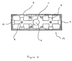
- FIG. 1 shows a prior art dryer.
- the dryer comprises first and second drying towers 1, 2 containing desiccant material.
- the towers 1,2 are generally cylindrical and are disposed in an upright orientation.
- Gas to be dried is received by an inlet pipe 5 from where it is conveyed to the towers 1,2 through an inlet system of pipes and valves contained within a manifold 3 mounted on the towers 1,2.
- Gas exiting from the towers 1,2 is received by an outlet system of pipes and valves contained within manifold 4 mounted below the towers 1,2.
- connection block shown in figure 2 as a plan view.
- connection block includes a body 6 which is preferably of a rectangular shape. Inside the block is a first set of cruciform gas passages 7 and a second set of cruciform gas passages 8. Each set of passages has three exits from the block, one at the end of three arms of the cruciform. Accordingly, the rectangular block has one aperture 9, 10 at each end of the block (on the two short sides of the rectangle) and two apertures on each long side of the rectangle, six apertures in total.
- connection block shown in Figure 2 is for connection to a manifold.
- the connection block has an inlet 11 to the manifold and an outlet 12 from the manifold.
- Gas can enter the connection block through any of the apertures associated with the set of cruciform gas passages that lead to the inlet 11.
- gas could enter via aperture 9 and flow in a straight path to the inlet 11 which is in fluid combination with a gas passage in the manifold.
- the inlet and outlet to and from the manifold can be reversed.
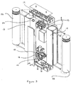
- FIG. 3 A preferred embodiment of the dryer according to the present invention is shown in Figure 3.
- a heatless down-flow dryer is used as an example.
- the invention is not restricted in application to dryers of this type.
- a dryer of the invention comprises first and second drying towers 13,14, each containing desiccant material.
- the desiccant material may be constrained only by the tower but preferably, cartridges 22,23 of desiccant material are inserted into the towers 13,14.
- the cartridges 22,23 are generally cylindrical and the towers 13,14 are disposed in an upright orientation.
- Each tower 13,14 has an upper port 24 and a lower port, through which gas can pass into and out of the tower.
- a first manifold 15 is connected to the upper ports of both towers and a second manifold 16 is connected to the lower ports of both towers.
- the two manifolds are constructed as identical castings.
- Various materials can be used for the casting ranging from aluminium alloys to spheroidal graphite iron to polycarbonate composite plastics.
- the exhaust valve actuators include a diaphragm under a cap which is sealed against a first sealing surface and which can be urged against a second sealing surface to close the port connected thereto.
- the diaphragm may be operated by a solenoid or under pneumatic control, as is convenient, or it may be self-actuating.
- Each exhaust valve must be sufficiently large to allow a desiccant tower to reduce from full line pressure to atmospheric pressure in a matter of seconds.
- the first manifold does not have exhaust valves but, as both manifolds are identical in moulded structure, there are cavities within the manifold in place of the valve actuators. Those cavities are blanked off so that gas cannot escape from the manifold but there is a passage passing between the two cavities through which purge gas channeled from the outlet stream of dry gas can pass. It is desirable to be able to control the flow of purge gas and this can be done using a restriction element which is inserted through an aperture in the manifold wall. This allows for easy removal of the restriction element for replacement by an alternative element with different flow characteristics. Thus purge flow can be controlled without the manifold being dismantled.
- Both manifolds have a valve, preferably at the heart of the manifold. This is preferably a shuttle valve which has an actuator that can "shuttle" between two positions thus controlling the passage of gas.
- the drier also includes a connection block 19 which is identical to that shown in Figure 2.
- the connection block is seated on the manifold and provides an inlet and outlet into the manifold.
- a demand valve can be located at outlet 12 comprising a piston and a spring. If the gas pressure is below a predetermined threshold, the force of the gas is insufficient to depress the spring and the piston remains in a position in which the exit to the connection block (or other outlet pipe) is concealed. When the gas pressure reaches the threshold, the spring is compressed and the piston moves in the direction of the gas flow, revealing the exit to the connection block as it moves so that the gas can exit the manifold.
Landscapes
- Chemical & Material Sciences (AREA)
- Engineering & Computer Science (AREA)
- Analytical Chemistry (AREA)
- General Chemical & Material Sciences (AREA)
- Oil, Petroleum & Natural Gas (AREA)
- Chemical Kinetics & Catalysis (AREA)
- Drying Of Gases (AREA)
- Separation Of Gases By Adsorption (AREA)
- Transition And Organic Metals Composition Catalysts For Addition Polymerization (AREA)
Claims (15)
- Adsorptionsgastrockner in Kombination mit einem Anschlussblock (19), wobei der Adsorptionsgastrockner einen ersten Trockenturm (13) und einen zweiten Trockenturm (14), die jeweils eine erste Durchlassöffnung (24) und eine zweite Durchlassöffnung aufweisen, durch die Gas in den Turm hinein- oder aus demselben herausströmen kann, sowie ein erstes Verteilerstück (15) und ein zweites Verteilerstück (16) aufweist, die jeweils mit der ersten und der zweiten Durchlassöffnung beider Türme (13, 14) verbunden sind, wobei die Verteilerstücke (15, 16) jeweils integrierte Gasdurchlässe aufweisen, wobei jede Durchlassöffnung der Türme (13, 14) in Kommunikation mit einem Gasdurchlass steht, und wobei die Verteilerstücke (15, 16) jeweils zumindest einen integrierten Ventilsitz aufweisen, auf dem eine Ventilbetätigungsvorrichtung befestigt ist, um ein Ventil zur Steuerung des Gasflusses durch die Gasdurchlässe auszubilden, und das zweite Verteilerstück (16) zwei Auslassventile (17, 18) zur Steuerung eines Spülgases umfasst,
dadurch gekennzeichnet, dass der Anschlussblock (19) zum Anschließen an ein Verteilerstück (15) des Trockners vorgesehen ist und zwei Sätze Gasdurchlässe (7, 8) umfasst, wobei jeder Satz eine Kreuzform innerhalb des Blocks (19) ausbildet und jeder Satz (7, 8) bis zu drei Schenkeln der Kreuzform aufweist, die zu einem Ausgang aus dem Block heraus führen, während der vierte Schenkel eines Satzes einen Einlass in das Verteilerstück (15) aufweist und der vierte Arm des anderen Satzes einen Auslass aus dem Verteilerstück (15) heraus bildet. - Adsorptionsgastrockner nach Anspruch 1, worin die Auslassventile (17, 18) im zweiten Verteilerstück (16) aneinander angrenzend angeordnet sind.
- Adsorptionsgastrockner nach Anspruch 1 oder 2, worin jedes Verteilerstück (15, 16) als ein Gussstück ausgebildet ist.
- Adsorptionsgastrockner nach einem der Ansprüche 1 bis 3, worin das zweite Verteilerstück (15) als Nassgas-Einlass und das erste Verteilerstück (16) als Trockengas-Auslass dient.
- Adsorptionsgastrockner nach Anspruch 4, worin die Gussform für jedes Verteilerstück (15, 16) identisch ist.
- Adsorptionsgastrockner nach Anspruch 5, worin die durch die Auslassventile (17, 18) im zweiten Verteilerstück (16) belegte Position in der Gussform im ersten Verteilerstück (15) frei bleibt.
- Adsorptionsgastrockner nach Anspruch 6, worin im ersten Verteilerstück (15) zwei Hohlräume ohne Ventile vorhanden sind, wobei die zwei Hohlräume durch einen Gasdurchlass miteinander verbunden sind, durch den das Spülgas hindurchströmen kann.
- Adsorptionsgastrockner nach Anspruch 7, worin das erste Verteilerstück (15) eine Öffnung aufweist, die einen Ausgang vom Spülgasdurchlass zur Außenumgebung des Verteilerstücks (15) bereitstellt, wobei diese Öffnung blockiert ist, damit sichergestellt werden kann, dass das Spülgas das Verteilerstück (15) nicht durch die Öffnung verlässt.
- Adsorptionsgastrockner nach Anspruch 8, worin die Öffnung unter Verwendung eines Restriktionselements blockiert ist, welches den Spülgasfluss auf eine vorbestimmte Menge einschränkt.
- Adsorptionsgastrockner nach einem der Ansprüche 1 bis 9, umfassend zwei ähnliche Türme (13, 14), wobei jeder eine obere Durchlassöffnung (24) und eine untere Durchlassöffnung sowie obere und untere Verteilerstücke (15, 16) aufweist, wobei das obere Verteilerstück (15) mit den oberen Durchlassöffnungen (24) beider Türme (13, 14) und das untere Verteilerstück (16) mit den unteren Durchlassöffnungen beider Türme (13, 14) verbunden ist und das erste Verteilerstück (15) das obere Verteilerstück und das zweite Verteilerstück das untere Verteilerstück ist.
- Adsorptionsgastrockner nach einem der Ansprüche 1 bis 10, worin O-Ringe in den Düsen der Türme (13, 14) positioniert sind, um Abdichtungen mit den Verteilerstücken (13, 14) bereitzustellen.
- Adsorptionsgastrockner nach einem der Ansprüche 1 bis 11, worin die Auslassventile (17, 18) servo-gesteuerte Membranventile sind.
- Adsorptionsgastrockner nach Anspruch 12, worin das zweite Verteilerstück (16) ein Wechselventil zur Leitung des Nassgases in den in Betrieb genommenen Turm umfasst, wobei die Bewegung des Wechselventils durch die Auslassventile (17, 18) gesteuert wird.
- Adsorptionsgastrockner nach einem der Ansprüche 1 bis 13, worin zumindest eines der Verteilerstücke (15, 16) ein Zufuhrventil beinhaltet, welches einen federbelasteten Kolben umfasst, so dass lediglich im Falle eines ausreichend vorhandenen Gasdrucks die Feder zusammengedrückt und der Kolben in die Richtung des Gasflusses bewegt wird, um den Eintritt des Gasflusses in einen Gasdurchlass zu ermöglichen, der nur dann offengelegt wird, wenn der Kolben gedrückt wird.
- Adsorptionsgastrockner in Kombination mit einem Anschlussblock nach einem der Ansprüche 1 bis 14, worin der Anschlussblock zusätzliche Gasdurchlässe aufweist, die zur Außenumgebung des Blocks (19) führen und von den Kreuzform-Durchlässen (7, 8) abzweigen.
Applications Claiming Priority (2)
| Application Number | Priority Date | Filing Date | Title |
|---|---|---|---|
| GBGB0215649.5A GB0215649D0 (en) | 2002-07-05 | 2002-07-05 | Adsorption gas dryer |
| GB0215649 | 2002-07-05 |
Publications (3)
| Publication Number | Publication Date |
|---|---|
| EP1378286A2 EP1378286A2 (de) | 2004-01-07 |
| EP1378286A3 EP1378286A3 (de) | 2004-03-03 |
| EP1378286B1 true EP1378286B1 (de) | 2007-03-28 |
Family
ID=9939949
Family Applications (1)
| Application Number | Title | Priority Date | Filing Date |
|---|---|---|---|
| EP03253901A Expired - Lifetime EP1378286B1 (de) | 2002-07-05 | 2003-06-20 | Adsorptionsgastrockner |
Country Status (6)
| Country | Link |
|---|---|
| US (1) | US6953498B2 (de) |
| EP (1) | EP1378286B1 (de) |
| AT (1) | ATE357963T1 (de) |
| CA (1) | CA2433273A1 (de) |
| DE (1) | DE60312775T2 (de) |
| GB (1) | GB0215649D0 (de) |
Cited By (1)
| Publication number | Priority date | Publication date | Assignee | Title |
|---|---|---|---|---|
| EP3242736B1 (de) * | 2015-01-07 | 2023-01-11 | Norgren Limited | Doppelter filter zur entfernung von feuchtigkeit aus einem flüssigkeitsstrom |
Families Citing this family (31)
| Publication number | Priority date | Publication date | Assignee | Title |
|---|---|---|---|---|
| US6755895B2 (en) * | 2002-04-09 | 2004-06-29 | H2Gen Innovations, Inc. | Method and apparatus for pressure swing adsorption |
| US7135059B2 (en) * | 2003-10-07 | 2006-11-14 | Inogen, Inc. | Portable gas fractionalization system |
| US7066985B2 (en) * | 2003-10-07 | 2006-06-27 | Inogen, Inc. | Portable gas fractionalization system |
| US20050072423A1 (en) | 2003-10-07 | 2005-04-07 | Deane Geoffrey Frank | Portable gas fractionalization system |
| US20050072426A1 (en) * | 2003-10-07 | 2005-04-07 | Deane Geoffrey Frank | Portable gas fractionalization system |
| JP2007508052A (ja) | 2003-10-07 | 2007-04-05 | アイノゲン、インコーポレイテッド | 携帯型ガス分離システム |
| EP1812141B1 (de) * | 2004-10-12 | 2012-12-19 | Airsep Corporation | Tragbarer sauerstoffkonzentrator |
| US7766010B2 (en) | 2005-02-09 | 2010-08-03 | Vbox, Incorporated | Method of controlling the rate of oxygen produced by an oxygen concentrator |
| US7866315B2 (en) | 2005-02-09 | 2011-01-11 | Vbox, Incorporated | Method and apparatus for controlling the purity of oxygen produced by an oxygen concentrator |
| US20060174875A1 (en) * | 2005-02-09 | 2006-08-10 | Vbox, Incorporated | Ambulatory oxygen concentrator containing a power pack |
| US7431032B2 (en) * | 2005-02-09 | 2008-10-07 | Vbox Incorporated | Low power ambulatory oxygen concentrator |
| US7171963B2 (en) * | 2005-02-09 | 2007-02-06 | Vbox, Incorporated | Product pump for an oxygen concentrator |
| US8020553B2 (en) * | 2005-02-09 | 2011-09-20 | Vbox, Incorporated | Ambulatory oxygen concentrator containing a three phase vacuum separation system |
| US7121276B2 (en) * | 2005-02-09 | 2006-10-17 | Vbox, Incorporated | Personal oxygen concentrator |
| US7604005B2 (en) | 2005-02-09 | 2009-10-20 | Vbox Incorporated | Adsorbent cartridge for oxygen concentrator |
| US7954490B2 (en) * | 2005-02-09 | 2011-06-07 | Vbox, Incorporated | Method of providing ambulatory oxygen |
| US7288189B2 (en) * | 2005-02-11 | 2007-10-30 | Bonifer Jeffery P | Multi-faceted intake filter for an aquarium |
| US7686870B1 (en) | 2005-12-29 | 2010-03-30 | Inogen, Inc. | Expandable product rate portable gas fractionalization system |
| GB0719917D0 (en) | 2007-10-11 | 2007-11-21 | Walker Filtration Ltd | Regenerative adsorption gas dryer |
| US8753428B2 (en) * | 2009-06-29 | 2014-06-17 | Lummus Technology Inc. | Method and manifold for carrying reduced moment due to dimensional change in pressure vessel; removable insert with valve seat; pressure assisted valve arrangement and method |
| US8695600B2 (en) | 2009-07-22 | 2014-04-15 | Vbox, Incorporated | Method of separating and distributing oxygen |
| CN102218256B (zh) * | 2011-07-08 | 2013-08-21 | 珠海市海夫实业发展有限公司 | 吸附式压缩空气干燥机 |
| JP5933467B2 (ja) * | 2013-02-19 | 2016-06-08 | 大陽日酸株式会社 | ガス処理装置 |
| US9375679B2 (en) | 2013-08-30 | 2016-06-28 | Haldex Brake Products Corporation | Air dryer assembly with manifold system |
| TWI552957B (zh) | 2014-12-15 | 2016-10-11 | 財團法人工業技術研究院 | 二氧化碳吸附與回收系統及方法 |
| KR102194968B1 (ko) * | 2016-03-18 | 2020-12-28 | 엑손모빌 업스트림 리서치 캄파니 | 관련 스윙 흡착 공정을 위한 장치 및 시스템 |
| CN106090330B (zh) * | 2016-07-07 | 2018-11-27 | 珠海市臻的科技有限公司 | 一种壁挂式干燥装置 |
| EP3600606B1 (de) * | 2017-03-30 | 2021-03-03 | Parker Hannifin Manufacturing Limited | Druckwechseladsorptionssystem mit variablem durchflussbegrenzer |
| WO2019178556A1 (en) * | 2018-03-16 | 2019-09-19 | Dirtt Environmental Solutions Inc. | Med-gas panel connectors for reconfigurable walls |
| CN110038398B (zh) * | 2019-04-18 | 2024-02-02 | 无锡迈格艾尔净化设备有限公司 | 微型干燥机 |
| CN111467930A (zh) * | 2020-05-15 | 2020-07-31 | 华蓝达废气治理湖北有限公司 | 一种紧凑型活性炭催化燃烧废气处理柜及其一体机 |
Family Cites Families (18)
| Publication number | Priority date | Publication date | Assignee | Title |
|---|---|---|---|---|
| US3080977A (en) * | 1960-05-06 | 1963-03-12 | Henry Valve Co | Drier fitting and assembly |
| FR2550466A1 (fr) * | 1983-08-12 | 1985-02-15 | Pyrelem | Appareil de purification et de sechage d'air comprime |
| US4512781A (en) * | 1983-11-14 | 1985-04-23 | Pittsburgh Brass Manufacturing Company | Shuttle valves and system for fluid control |
| US4687573A (en) * | 1984-08-13 | 1987-08-18 | Pall Corporation | Sorbing apparatus |
| SE459397B (sv) * | 1987-05-07 | 1989-07-03 | Garphyttan Haldex Ab | Ventil i en tvaatorns luftfuktare |
| US4877429A (en) * | 1989-03-06 | 1989-10-31 | Hunter Donald W | Valve device for P.S.A. or R.P.S.A. systems |
| DD283074A5 (de) * | 1989-05-10 | 1990-10-03 | Dresden Komplette Chemieanlag | Druckwechseladsorptionsanlage zum trennen von gasgemischen |
| US5174798A (en) * | 1992-03-10 | 1992-12-29 | Ingersoll-Rand Company | Multiple filter cartridge position limiting device |
| US5344474A (en) * | 1993-04-28 | 1994-09-06 | Air Dry Corporation Of America | Gas separation device |
| US5286282A (en) * | 1993-05-04 | 1994-02-15 | Allied-Signal Inc. | Continuous flow air dryer with double helix split desiccant bed |
| DE4320942A1 (de) * | 1993-06-24 | 1995-01-05 | Carbotech Anlagenbau Gmbh | Adsorptionsbehälter für Kohlenstoffmolekularsieb |
| GB2318150B (en) | 1996-10-09 | 2000-02-16 | Brian Walker | Adsorption gas dryer two stage silencers with integral bypass |
| WO1998018538A2 (de) * | 1996-10-31 | 1998-05-07 | Ultrafilter Gmbh | Adsorptionstrockneranlage und verfahren und vorrichtung zu ihrer funktionsüberprüfung |
| US5961698A (en) * | 1998-02-02 | 1999-10-05 | Westinghouse Air Brake Company | Twin tower air dryer |
| US6096115A (en) * | 1998-11-25 | 2000-08-01 | Air Products And Chemicals, Inc. | Pressure swing adsorption process and system utilizing two product storage tanks |
| US6478850B2 (en) * | 2000-08-02 | 2002-11-12 | Wearair Oxygen Inc. | Miniaturized wearable oxygen concentrator |
| US6581297B1 (en) * | 2000-11-17 | 2003-06-24 | Graham-White Manufacturing Company | Drying apparatus and method |
| US6755895B2 (en) * | 2002-04-09 | 2004-06-29 | H2Gen Innovations, Inc. | Method and apparatus for pressure swing adsorption |
-
2002
- 2002-07-05 GB GBGB0215649.5A patent/GB0215649D0/en not_active Ceased
-
2003
- 2003-06-20 AT AT03253901T patent/ATE357963T1/de not_active IP Right Cessation
- 2003-06-20 DE DE60312775T patent/DE60312775T2/de not_active Expired - Fee Related
- 2003-06-20 EP EP03253901A patent/EP1378286B1/de not_active Expired - Lifetime
- 2003-06-25 CA CA002433273A patent/CA2433273A1/en not_active Abandoned
- 2003-07-03 US US10/611,957 patent/US6953498B2/en not_active Expired - Fee Related
Cited By (1)
| Publication number | Priority date | Publication date | Assignee | Title |
|---|---|---|---|---|
| EP3242736B1 (de) * | 2015-01-07 | 2023-01-11 | Norgren Limited | Doppelter filter zur entfernung von feuchtigkeit aus einem flüssigkeitsstrom |
Also Published As
| Publication number | Publication date |
|---|---|
| DE60312775T2 (de) | 2008-01-24 |
| EP1378286A2 (de) | 2004-01-07 |
| ATE357963T1 (de) | 2007-04-15 |
| US20040020366A1 (en) | 2004-02-05 |
| CA2433273A1 (en) | 2004-01-05 |
| EP1378286A3 (de) | 2004-03-03 |
| US6953498B2 (en) | 2005-10-11 |
| DE60312775D1 (de) | 2007-05-10 |
| GB0215649D0 (en) | 2002-08-14 |
Similar Documents
| Publication | Publication Date | Title |
|---|---|---|
| EP1378286B1 (de) | Adsorptionsgastrockner | |
| KR102123224B1 (ko) | 복수의 밸브들을 갖는 관련 스윙 흡착 공정을 위한 장치 및 시스템 | |
| US6036754A (en) | Adsorption gas dryer | |
| CN108883358A (zh) | 用于与其相关的变吸附工艺的装置和系统 | |
| KR20070116941A (ko) | 조습장치 | |
| WO1998012089A1 (en) | Air braking system component | |
| US4738692A (en) | Gas drying apparatus | |
| EP1171221B1 (de) | Schieberventil zur steuerung von luftströmungen zwischen zwei adsorptionsbetten | |
| US9480945B2 (en) | Pressure swing adsorption apparatus | |
| CA2267013C (en) | Switching valve for multi-chamber adsorbent air and gas fractionation system | |
| JP2008508466A5 (de) | ||
| EP2205339B1 (de) | Regenerative adsorptionsgastrocknungsvorrichtung | |
| CN103062439A (zh) | 进气阀组件 | |
| WO2006107349A1 (en) | Pulse purge regenerative gas dryer | |
| KR102509454B1 (ko) | 에어드라이어 및 이를 이용한 압축공기 건조 방법 | |
| JP4908700B2 (ja) | 吸着分離装置 | |
| KR20180042222A (ko) | 가스를 압축 및 건조하는 방법 및 장치 | |
| EP0332724B1 (de) | Verfahren zur Gastrocknung | |
| JP2010151404A (ja) | 粉粒体材料の除湿乾燥装置、及び粉粒体材料の除湿乾燥方法 | |
| GB2319585A (en) | Adsorption gas dryer with cast manifold and integral valving | |
| CA1277925C (en) | Gas drying apparatus | |
| JP3005059U (ja) | 低温空気発生装置 | |
| JP4351174B2 (ja) | 圧縮気体の除湿における継続供給方法及び圧縮気体の除湿装置 | |
| JPS61125421A (ja) | 加熱再生式吸着塔及び圧縮気体除湿装置 | |
| JPWO2021229314A5 (de) |
Legal Events
| Date | Code | Title | Description |
|---|---|---|---|
| PUAI | Public reference made under article 153(3) epc to a published international application that has entered the european phase |
Free format text: ORIGINAL CODE: 0009012 |
|
| AK | Designated contracting states |
Kind code of ref document: A2 Designated state(s): AT BE BG CH CY CZ DE DK EE ES FI FR GB GR HU IE IT LI LU MC NL PT RO SE SI SK TR |
|
| AX | Request for extension of the european patent |
Extension state: AL LT LV MK |
|
| PUAL | Search report despatched |
Free format text: ORIGINAL CODE: 0009013 |
|
| AK | Designated contracting states |
Kind code of ref document: A3 Designated state(s): AT BE BG CH CY CZ DE DK EE ES FI FR GB GR HU IE IT LI LU MC NL PT RO SE SI SK TR |
|
| AX | Request for extension of the european patent |
Extension state: AL LT LV MK |
|
| 17P | Request for examination filed |
Effective date: 20040420 |
|
| AKX | Designation fees paid |
Designated state(s): AT BE BG CH CY CZ DE DK EE ES FI FR GB GR HU IE IT LI LU MC NL PT RO SE SI SK TR |
|
| 17Q | First examination report despatched |
Effective date: 20041102 |
|
| GRAP | Despatch of communication of intention to grant a patent |
Free format text: ORIGINAL CODE: EPIDOSNIGR1 |
|
| GRAS | Grant fee paid |
Free format text: ORIGINAL CODE: EPIDOSNIGR3 |
|
| GRAA | (expected) grant |
Free format text: ORIGINAL CODE: 0009210 |
|
| AK | Designated contracting states |
Kind code of ref document: B1 Designated state(s): AT BE BG CH CY CZ DE DK EE ES FI FR GB GR HU IE IT LI LU MC NL PT RO SE SI SK TR |
|
| PG25 | Lapsed in a contracting state [announced via postgrant information from national office to epo] |
Ref country code: NL Free format text: LAPSE BECAUSE OF FAILURE TO SUBMIT A TRANSLATION OF THE DESCRIPTION OR TO PAY THE FEE WITHIN THE PRESCRIBED TIME-LIMIT Effective date: 20070328 Ref country code: FI Free format text: LAPSE BECAUSE OF FAILURE TO SUBMIT A TRANSLATION OF THE DESCRIPTION OR TO PAY THE FEE WITHIN THE PRESCRIBED TIME-LIMIT Effective date: 20070328 Ref country code: CH Free format text: LAPSE BECAUSE OF FAILURE TO SUBMIT A TRANSLATION OF THE DESCRIPTION OR TO PAY THE FEE WITHIN THE PRESCRIBED TIME-LIMIT Effective date: 20070328 Ref country code: LI Free format text: LAPSE BECAUSE OF FAILURE TO SUBMIT A TRANSLATION OF THE DESCRIPTION OR TO PAY THE FEE WITHIN THE PRESCRIBED TIME-LIMIT Effective date: 20070328 Ref country code: SI Free format text: LAPSE BECAUSE OF FAILURE TO SUBMIT A TRANSLATION OF THE DESCRIPTION OR TO PAY THE FEE WITHIN THE PRESCRIBED TIME-LIMIT Effective date: 20070328 Ref country code: AT Free format text: LAPSE BECAUSE OF FAILURE TO SUBMIT A TRANSLATION OF THE DESCRIPTION OR TO PAY THE FEE WITHIN THE PRESCRIBED TIME-LIMIT Effective date: 20070328 |
|
| REG | Reference to a national code |
Ref country code: GB Ref legal event code: FG4D |
|
| REG | Reference to a national code |
Ref country code: CH Ref legal event code: EP |
|
| REF | Corresponds to: |
Ref document number: 60312775 Country of ref document: DE Date of ref document: 20070510 Kind code of ref document: P |
|
| REG | Reference to a national code |
Ref country code: IE Ref legal event code: FG4D |
|
| PGFP | Annual fee paid to national office [announced via postgrant information from national office to epo] |
Ref country code: DE Payment date: 20070529 Year of fee payment: 5 |
|
| PGFP | Annual fee paid to national office [announced via postgrant information from national office to epo] |
Ref country code: BE Payment date: 20070530 Year of fee payment: 5 |
|
| PG25 | Lapsed in a contracting state [announced via postgrant information from national office to epo] |
Ref country code: SE Free format text: LAPSE BECAUSE OF FAILURE TO SUBMIT A TRANSLATION OF THE DESCRIPTION OR TO PAY THE FEE WITHIN THE PRESCRIBED TIME-LIMIT Effective date: 20070628 |
|
| PG25 | Lapsed in a contracting state [announced via postgrant information from national office to epo] |
Ref country code: ES Free format text: LAPSE BECAUSE OF FAILURE TO SUBMIT A TRANSLATION OF THE DESCRIPTION OR TO PAY THE FEE WITHIN THE PRESCRIBED TIME-LIMIT Effective date: 20070709 |
|
| PG25 | Lapsed in a contracting state [announced via postgrant information from national office to epo] |
Ref country code: PT Free format text: LAPSE BECAUSE OF FAILURE TO SUBMIT A TRANSLATION OF THE DESCRIPTION OR TO PAY THE FEE WITHIN THE PRESCRIBED TIME-LIMIT Effective date: 20070828 |
|
| ET | Fr: translation filed | ||
| REG | Reference to a national code |
Ref country code: CH Ref legal event code: PL |
|
| NLV1 | Nl: lapsed or annulled due to failure to fulfill the requirements of art. 29p and 29m of the patents act | ||
| PG25 | Lapsed in a contracting state [announced via postgrant information from national office to epo] |
Ref country code: SK Free format text: LAPSE BECAUSE OF FAILURE TO SUBMIT A TRANSLATION OF THE DESCRIPTION OR TO PAY THE FEE WITHIN THE PRESCRIBED TIME-LIMIT Effective date: 20070328 |
|
| PGFP | Annual fee paid to national office [announced via postgrant information from national office to epo] |
Ref country code: GB Payment date: 20070518 Year of fee payment: 5 |
|
| PG25 | Lapsed in a contracting state [announced via postgrant information from national office to epo] |
Ref country code: RO Free format text: LAPSE BECAUSE OF FAILURE TO SUBMIT A TRANSLATION OF THE DESCRIPTION OR TO PAY THE FEE WITHIN THE PRESCRIBED TIME-LIMIT Effective date: 20070328 Ref country code: CZ Free format text: LAPSE BECAUSE OF FAILURE TO SUBMIT A TRANSLATION OF THE DESCRIPTION OR TO PAY THE FEE WITHIN THE PRESCRIBED TIME-LIMIT Effective date: 20070328 |
|
| PG25 | Lapsed in a contracting state [announced via postgrant information from national office to epo] |
Ref country code: MC Free format text: LAPSE BECAUSE OF NON-PAYMENT OF DUE FEES Effective date: 20070630 Ref country code: DK Free format text: LAPSE BECAUSE OF FAILURE TO SUBMIT A TRANSLATION OF THE DESCRIPTION OR TO PAY THE FEE WITHIN THE PRESCRIBED TIME-LIMIT Effective date: 20070328 |
|
| PLBE | No opposition filed within time limit |
Free format text: ORIGINAL CODE: 0009261 |
|
| STAA | Information on the status of an ep patent application or granted ep patent |
Free format text: STATUS: NO OPPOSITION FILED WITHIN TIME LIMIT |
|
| 26N | No opposition filed |
Effective date: 20080102 |
|
| PG25 | Lapsed in a contracting state [announced via postgrant information from national office to epo] |
Ref country code: IT Free format text: LAPSE BECAUSE OF FAILURE TO SUBMIT A TRANSLATION OF THE DESCRIPTION OR TO PAY THE FEE WITHIN THE PRESCRIBED TIME-LIMIT Effective date: 20070328 Ref country code: GR Free format text: LAPSE BECAUSE OF FAILURE TO SUBMIT A TRANSLATION OF THE DESCRIPTION OR TO PAY THE FEE WITHIN THE PRESCRIBED TIME-LIMIT Effective date: 20070629 |
|
| PGFP | Annual fee paid to national office [announced via postgrant information from national office to epo] |
Ref country code: FR Payment date: 20070524 Year of fee payment: 5 |
|
| PG25 | Lapsed in a contracting state [announced via postgrant information from national office to epo] |
Ref country code: IE Free format text: LAPSE BECAUSE OF NON-PAYMENT OF DUE FEES Effective date: 20070620 |
|
| BERE | Be: lapsed |
Owner name: WALKER FILTRATION LTD Effective date: 20080630 |
|
| PG25 | Lapsed in a contracting state [announced via postgrant information from national office to epo] |
Ref country code: EE Free format text: LAPSE BECAUSE OF FAILURE TO SUBMIT A TRANSLATION OF THE DESCRIPTION OR TO PAY THE FEE WITHIN THE PRESCRIBED TIME-LIMIT Effective date: 20070328 |
|
| GBPC | Gb: european patent ceased through non-payment of renewal fee |
Effective date: 20080620 |
|
| PG25 | Lapsed in a contracting state [announced via postgrant information from national office to epo] |
Ref country code: BE Free format text: LAPSE BECAUSE OF NON-PAYMENT OF DUE FEES Effective date: 20080630 |
|
| PG25 | Lapsed in a contracting state [announced via postgrant information from national office to epo] |
Ref country code: DE Free format text: LAPSE BECAUSE OF NON-PAYMENT OF DUE FEES Effective date: 20090101 |
|
| PG25 | Lapsed in a contracting state [announced via postgrant information from national office to epo] |
Ref country code: GB Free format text: LAPSE BECAUSE OF NON-PAYMENT OF DUE FEES Effective date: 20080620 |
|
| PG25 | Lapsed in a contracting state [announced via postgrant information from national office to epo] |
Ref country code: CY Free format text: LAPSE BECAUSE OF FAILURE TO SUBMIT A TRANSLATION OF THE DESCRIPTION OR TO PAY THE FEE WITHIN THE PRESCRIBED TIME-LIMIT Effective date: 20070328 |
|
| PG25 | Lapsed in a contracting state [announced via postgrant information from national office to epo] |
Ref country code: BG Free format text: LAPSE BECAUSE OF FAILURE TO SUBMIT A TRANSLATION OF THE DESCRIPTION OR TO PAY THE FEE WITHIN THE PRESCRIBED TIME-LIMIT Effective date: 20070628 Ref country code: LU Free format text: LAPSE BECAUSE OF NON-PAYMENT OF DUE FEES Effective date: 20070620 |
|
| PG25 | Lapsed in a contracting state [announced via postgrant information from national office to epo] |
Ref country code: TR Free format text: LAPSE BECAUSE OF FAILURE TO SUBMIT A TRANSLATION OF THE DESCRIPTION OR TO PAY THE FEE WITHIN THE PRESCRIBED TIME-LIMIT Effective date: 20070328 Ref country code: HU Free format text: LAPSE BECAUSE OF FAILURE TO SUBMIT A TRANSLATION OF THE DESCRIPTION OR TO PAY THE FEE WITHIN THE PRESCRIBED TIME-LIMIT Effective date: 20070929 |
|
| REG | Reference to a national code |
Ref country code: FR Ref legal event code: ST Effective date: 20110708 |
|
| PG25 | Lapsed in a contracting state [announced via postgrant information from national office to epo] |
Ref country code: FR Free format text: LAPSE BECAUSE OF NON-PAYMENT OF DUE FEES Effective date: 20080630 |