EP1378286B1 - Adsorption gas dryer - Google Patents
Adsorption gas dryer Download PDFInfo
- Publication number
- EP1378286B1 EP1378286B1 EP03253901A EP03253901A EP1378286B1 EP 1378286 B1 EP1378286 B1 EP 1378286B1 EP 03253901 A EP03253901 A EP 03253901A EP 03253901 A EP03253901 A EP 03253901A EP 1378286 B1 EP1378286 B1 EP 1378286B1
- Authority
- EP
- European Patent Office
- Prior art keywords
- manifold
- gas
- dryer
- adsorption
- towers
- Prior art date
- Legal status (The legal status is an assumption and is not a legal conclusion. Google has not performed a legal analysis and makes no representation as to the accuracy of the status listed.)
- Expired - Lifetime
Links
- 238000001179 sorption measurement Methods 0.000 title claims abstract description 29
- 238000010926 purge Methods 0.000 claims abstract description 28
- 238000001035 drying Methods 0.000 claims abstract description 13
- 238000004891 communication Methods 0.000 claims abstract description 3
- 238000005266 casting Methods 0.000 claims description 8
- 230000000994 depressogenic effect Effects 0.000 claims description 2
- 239000007789 gas Substances 0.000 description 89
- 239000002274 desiccant Substances 0.000 description 15
- 239000000463 material Substances 0.000 description 7
- 230000001172 regenerating effect Effects 0.000 description 5
- 238000007789 sealing Methods 0.000 description 3
- 229910000838 Al alloy Inorganic materials 0.000 description 2
- 229910001141 Ductile iron Inorganic materials 0.000 description 2
- 230000015572 biosynthetic process Effects 0.000 description 2
- 230000009977 dual effect Effects 0.000 description 2
- 239000012530 fluid Substances 0.000 description 2
- 238000004519 manufacturing process Methods 0.000 description 2
- 238000000034 method Methods 0.000 description 2
- 239000004033 plastic Substances 0.000 description 2
- 229920003023 plastic Polymers 0.000 description 2
- 239000004417 polycarbonate Substances 0.000 description 2
- 229920000515 polycarbonate Polymers 0.000 description 2
- 229930091051 Arenine Natural products 0.000 description 1
- CWYNVVGOOAEACU-UHFFFAOYSA-N Fe2+ Chemical compound [Fe+2] CWYNVVGOOAEACU-UHFFFAOYSA-N 0.000 description 1
- 229910001296 Malleable iron Inorganic materials 0.000 description 1
- 239000002250 absorbent Substances 0.000 description 1
- 230000002745 absorbent Effects 0.000 description 1
- 239000011324 bead Substances 0.000 description 1
- 230000009286 beneficial effect Effects 0.000 description 1
- 239000002131 composite material Substances 0.000 description 1
- 150000001875 compounds Chemical class 0.000 description 1
- 238000010276 construction Methods 0.000 description 1
- 239000000428 dust Substances 0.000 description 1
- 238000010438 heat treatment Methods 0.000 description 1
- 238000012423 maintenance Methods 0.000 description 1
- 238000012986 modification Methods 0.000 description 1
- 230000004048 modification Effects 0.000 description 1
- 239000002245 particle Substances 0.000 description 1
- 238000005057 refrigeration Methods 0.000 description 1
- 230000008929 regeneration Effects 0.000 description 1
- 238000011069 regeneration method Methods 0.000 description 1
- 229920006395 saturated elastomer Polymers 0.000 description 1
- 239000002594 sorbent Substances 0.000 description 1
Images


Classifications
-
- B—PERFORMING OPERATIONS; TRANSPORTING
- B01—PHYSICAL OR CHEMICAL PROCESSES OR APPARATUS IN GENERAL
- B01D—SEPARATION
- B01D53/00—Separation of gases or vapours; Recovering vapours of volatile solvents from gases; Chemical or biological purification of waste gases, e.g. engine exhaust gases, smoke, fumes, flue gases, aerosols
- B01D53/02—Separation of gases or vapours; Recovering vapours of volatile solvents from gases; Chemical or biological purification of waste gases, e.g. engine exhaust gases, smoke, fumes, flue gases, aerosols by adsorption, e.g. preparative gas chromatography
- B01D53/04—Separation of gases or vapours; Recovering vapours of volatile solvents from gases; Chemical or biological purification of waste gases, e.g. engine exhaust gases, smoke, fumes, flue gases, aerosols by adsorption, e.g. preparative gas chromatography with stationary adsorbents
- B01D53/0407—Constructional details of adsorbing systems
- B01D53/0446—Means for feeding or distributing gases
-
- B—PERFORMING OPERATIONS; TRANSPORTING
- B01—PHYSICAL OR CHEMICAL PROCESSES OR APPARATUS IN GENERAL
- B01D—SEPARATION
- B01D53/00—Separation of gases or vapours; Recovering vapours of volatile solvents from gases; Chemical or biological purification of waste gases, e.g. engine exhaust gases, smoke, fumes, flue gases, aerosols
- B01D53/26—Drying gases or vapours
- B01D53/261—Drying gases or vapours by adsorption
-
- B—PERFORMING OPERATIONS; TRANSPORTING
- B01—PHYSICAL OR CHEMICAL PROCESSES OR APPARATUS IN GENERAL
- B01D—SEPARATION
- B01D2257/00—Components to be removed
- B01D2257/80—Water
-
- B—PERFORMING OPERATIONS; TRANSPORTING
- B01—PHYSICAL OR CHEMICAL PROCESSES OR APPARATUS IN GENERAL
- B01D—SEPARATION
- B01D2259/00—Type of treatment
- B01D2259/40—Further details for adsorption processes and devices
- B01D2259/40083—Regeneration of adsorbents in processes other than pressure or temperature swing adsorption
- B01D2259/40086—Regeneration of adsorbents in processes other than pressure or temperature swing adsorption by using a purge gas
-
- B—PERFORMING OPERATIONS; TRANSPORTING
- B01—PHYSICAL OR CHEMICAL PROCESSES OR APPARATUS IN GENERAL
- B01D—SEPARATION
- B01D2259/00—Type of treatment
- B01D2259/40—Further details for adsorption processes and devices
- B01D2259/402—Further details for adsorption processes and devices using two beds
-
- B—PERFORMING OPERATIONS; TRANSPORTING
- B01—PHYSICAL OR CHEMICAL PROCESSES OR APPARATUS IN GENERAL
- B01D—SEPARATION
- B01D53/00—Separation of gases or vapours; Recovering vapours of volatile solvents from gases; Chemical or biological purification of waste gases, e.g. engine exhaust gases, smoke, fumes, flue gases, aerosols
- B01D53/02—Separation of gases or vapours; Recovering vapours of volatile solvents from gases; Chemical or biological purification of waste gases, e.g. engine exhaust gases, smoke, fumes, flue gases, aerosols by adsorption, e.g. preparative gas chromatography
- B01D53/04—Separation of gases or vapours; Recovering vapours of volatile solvents from gases; Chemical or biological purification of waste gases, e.g. engine exhaust gases, smoke, fumes, flue gases, aerosols by adsorption, e.g. preparative gas chromatography with stationary adsorbents
- B01D53/0407—Constructional details of adsorbing systems
- B01D53/0415—Beds in cartridges
Definitions
- Adsorption dryers for compressed air and gases have been known for many years and are widely used throughout the world. Although other types of dryer are available, such as deliquescent and refrigeration dryers, these cannot give a pressure dew-point as low as that achieved by adsorption dryers and which is essential for many applications.
- adsorption dryers are dual tower dryers. That is to say, they include two towers of desiccant material (commonly known as beds) one of which is on stream' drying the gas whilst the other is being regenerated.
- the gas to be dried is passed through the desiccant bed of the on-stream tower continuously, in one direction, during a drying cycle. Then, after a predetermined time interval (this interval being chosen such that the bed will have adsorbed sufficient moisture) the inlet gas is switched to the desiccant bed of the other tower and the first desiccant bed is regenerated by some suitable procedure such as heating, evacuation or passing a purge gas through it, usually in a flow direction opposite to the flow of gas to be dried.
- Adsorption dryers are available in at least two distinct types: heat regenerative and heatless.
- a heat regenerative dryer uses heat in one form or another to reactivate the wet desiccant bed normally in conjunction with a flow of purge gas.
- a heatless dryer uses a purge flow of dry gas, which is usually a proportion of dried gas from the on-stream tower, the purge gas being passed through the regenerating bed at a lower pressure than the gas in the on-stream tower.
- Both types of dryer are normally operated on a fixed time cycle for drying and regeneration and both cycles are usually of an equal duration, or they can be operated in a variable cycle.
- the cycle times for heat regenerative dryers are usually measured in hours whereas for heatless dryers they are measured in minutes.
- valves To control the flow of gas from one tower to the other, and to control the purge gas, a series of valves is employed. These valves most typically include inlet valves which switch the gas from one tower to the other, exhaust valves which control the duration of purge gas flow and repressurisation of the towers, and outlet check valves which prevent the outlet stream pressurizing the off-stream bed. In addition to these valves, a number of other valves such as purge check valves, repressurisation valves, additional exhaust restrictor valves and so forth may be required.
- a dryer have a first and a second manifold for connection to the towers, each manifold having integral gas passages and at least one integral valve seat upon which a valve actuator is mounted.
- a drier is shown in Figure 1 in which there is provided two desiccant towers, 1 and 2 which each have an upper and lower port.
- a first manifold, 3, is connected to the two upper ports whilst a second manifold, 4, is connected to the two lower ports.
- Each manifold had four valves arranged in a linear formation within the manifold. This leads to a fairly bulky formation
- EP-A-0960646 discloses an adsorption gas dryer including first and second drying towers. First and second manifolds are connected respectively to first and second ports of both towers.
- US-4512781 discloses an apparatus system for drying gases in which flow to and from a pair of absorbent beds is controlled by shuttle valve units.
- US-B-6200365 discloses a device for fractionating a gas by adsorption.
- EP-A-0933118 discloses a twin tower gas drying system including a manifold block.
- US-4687573 discloses a sorbing apparatus having at least one chamber including a bed of sorbent particles.
- an adsorption gas dryer in combination with a connection block according to claim 1.
- connection block for connection to a manifold of the drier comprises two sets of gas passages, each set forming a cruciform shape within the block, each set having up to three arms of the cruciform leading to.an exit from the block, whilst the fourth arm of one set forms an inlet into the manifold and the fourth arm of the other set forms an outlet from the manifold.
- the number of joints is minimised so improving reliability and reducing leakage and the complexity of assembly.
- the passages within the manifold can be formed to a length and shape, and the valve seats can be positioned to exactly correspond with the positions of the towers, unlike in the prior art where the positions of the pipes is determined by the positions of the valve ports.
- the exhaust valves are arranged adjacent each other in the second manifold.
- the two exhaust valves are arranged side by side in the second manifold, a smaller, more compact structure can be achieved.
- Each manifold may be formed as a casting, for example of aluminium alloy, spheroidal graphite iron, or plastic material such as polycarbonate.
- one manifold acts as a wet gas inlet and the other manifold (the first manifold) as the dry gas outlet
- the casting for each manifold is identical as this will reduce manufacturing costs.
- the position in the cast occupied by the exhaust valves in the second manifold is left vacant in the first manifold i.e. two cavities with no valve actuator are present in the first manifold.
- these two cavities will be joined by a gas passage through which purge gas can flow.
- This purge gas will be dry gas which is bled off from the dry gas flowing to the outlet.
- the first manifold has an aperture which provides an exit from the purge gas passage way to the exterior of the manifold. This aperture will be blocked off to ensure that the purge gas does not exit the manifold via the aperture.
- the aperture is preferably blocked off using a restriction element that restricts the flow of purge gas by a predetermined amount.
- the restriction element may have an orifice of a smaller diameter than the purge gas passage. In this way, the restriction element may easily be replaced to vary the purge gas flow without requiring any disconnection of the manifold.
- a dryer of the present invention most commonly comprises two similar towers, each having an upper and a lower port, and upper and lower manifolds, the upper manifold being connected to the upper ports of both of the towers and the lower manifold being connected to the lower ports of both of the towers.
- the first manifold is the upper manifold and the second manifold is the lower manifold but this could be reversed.
- a dryer of the invention may be heatless or heat reactivated, up flow or down flow types of adsorption dryers.
- a control system for a dryer of the invention may be positioned within or on a manifold.
- embodiments of the present invention may use O-rings located in nozzles of the towers to provide seals with the manifolds. These O-rings serve two purposes in that they not only provide compound sealing between the manifold and the vessel towers, but that they also captively hold desiccant support screens in place in the towers so that the manifolds can be removed from the towers without fear that the desiccant beads will fall out of the towers, thus making maintenance a much simpler task.
- Embodiments of the invention can incorporate, for example, poppet or piston actuated valves or diaphragm valves.
- the exhaust valves are diaphragm valves. Most preferably, they are servo-controlled diaphragm valves.
- the second manifold includes a shuttle valve to direct wet gas into the appropriate i.e. on-stream tower. This shuttle valve "shuttles" between two positions, and the movement is preferably controlled by the exhaust valves.
- At least one of the manifold preferably includes a "demand" valve that comprises a spring-loaded piston. Gas will meet the piston and, only when the gas pressure is sufficient, the spring will be compressed and the piston moved in the direction of the gas flow to allow it to enter a gas passage revealed only when the piston is depressed. This ensures that the pressure within the dryer is adequate as it will not function if the pressure is too low.
- connection block allows multiple inlet/outlet options. For example, if each set of cruciform gas passages has three outlets from the block, there are nine possible options.
- the option of connecting gas pipes to numerous locations is beneficial. It also allows driers to be connected together e.g. face to face in a space efficient manner. Furthermore, it allows all other drier components to be disconnected, e.g. desiccant towers, control valve panels, leaving the cruciform connection block connected to the pipes and leaving the pipe system undisturbed.
- the gas passages may also be further exits from the gas passages, e.g. by other gas passages leading to the exterior of the block branching off from the cruciform passages.
- FIG. 1 shows a prior art dryer.
- the dryer comprises first and second drying towers 1, 2 containing desiccant material.
- the towers 1,2 are generally cylindrical and are disposed in an upright orientation.
- Gas to be dried is received by an inlet pipe 5 from where it is conveyed to the towers 1,2 through an inlet system of pipes and valves contained within a manifold 3 mounted on the towers 1,2.
- Gas exiting from the towers 1,2 is received by an outlet system of pipes and valves contained within manifold 4 mounted below the towers 1,2.
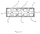
- connection block shown in figure 2 as a plan view.
- connection block includes a body 6 which is preferably of a rectangular shape. Inside the block is a first set of cruciform gas passages 7 and a second set of cruciform gas passages 8. Each set of passages has three exits from the block, one at the end of three arms of the cruciform. Accordingly, the rectangular block has one aperture 9, 10 at each end of the block (on the two short sides of the rectangle) and two apertures on each long side of the rectangle, six apertures in total.
- connection block shown in Figure 2 is for connection to a manifold.
- the connection block has an inlet 11 to the manifold and an outlet 12 from the manifold.
- Gas can enter the connection block through any of the apertures associated with the set of cruciform gas passages that lead to the inlet 11.
- gas could enter via aperture 9 and flow in a straight path to the inlet 11 which is in fluid combination with a gas passage in the manifold.
- the inlet and outlet to and from the manifold can be reversed.
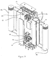
- FIG. 3 A preferred embodiment of the dryer according to the present invention is shown in Figure 3.
- a heatless down-flow dryer is used as an example.
- the invention is not restricted in application to dryers of this type.
- a dryer of the invention comprises first and second drying towers 13,14, each containing desiccant material.
- the desiccant material may be constrained only by the tower but preferably, cartridges 22,23 of desiccant material are inserted into the towers 13,14.
- the cartridges 22,23 are generally cylindrical and the towers 13,14 are disposed in an upright orientation.
- Each tower 13,14 has an upper port 24 and a lower port, through which gas can pass into and out of the tower.
- a first manifold 15 is connected to the upper ports of both towers and a second manifold 16 is connected to the lower ports of both towers.
- the two manifolds are constructed as identical castings.
- Various materials can be used for the casting ranging from aluminium alloys to spheroidal graphite iron to polycarbonate composite plastics.
- the exhaust valve actuators include a diaphragm under a cap which is sealed against a first sealing surface and which can be urged against a second sealing surface to close the port connected thereto.
- the diaphragm may be operated by a solenoid or under pneumatic control, as is convenient, or it may be self-actuating.
- Each exhaust valve must be sufficiently large to allow a desiccant tower to reduce from full line pressure to atmospheric pressure in a matter of seconds.
- the first manifold does not have exhaust valves but, as both manifolds are identical in moulded structure, there are cavities within the manifold in place of the valve actuators. Those cavities are blanked off so that gas cannot escape from the manifold but there is a passage passing between the two cavities through which purge gas channeled from the outlet stream of dry gas can pass. It is desirable to be able to control the flow of purge gas and this can be done using a restriction element which is inserted through an aperture in the manifold wall. This allows for easy removal of the restriction element for replacement by an alternative element with different flow characteristics. Thus purge flow can be controlled without the manifold being dismantled.
- Both manifolds have a valve, preferably at the heart of the manifold. This is preferably a shuttle valve which has an actuator that can "shuttle" between two positions thus controlling the passage of gas.
- the drier also includes a connection block 19 which is identical to that shown in Figure 2.
- the connection block is seated on the manifold and provides an inlet and outlet into the manifold.
- a demand valve can be located at outlet 12 comprising a piston and a spring. If the gas pressure is below a predetermined threshold, the force of the gas is insufficient to depress the spring and the piston remains in a position in which the exit to the connection block (or other outlet pipe) is concealed. When the gas pressure reaches the threshold, the spring is compressed and the piston moves in the direction of the gas flow, revealing the exit to the connection block as it moves so that the gas can exit the manifold.
Abstract
Description
- Adsorption dryers for compressed air and gases have been known for many years and are widely used throughout the world. Although other types of dryer are available, such as deliquescent and refrigeration dryers, these cannot give a pressure dew-point as low as that achieved by adsorption dryers and which is essential for many applications.
- Normally, adsorption dryers are dual tower dryers. That is to say, they include two towers of desiccant material (commonly known as beds) one of which is on stream' drying the gas whilst the other is being regenerated. In a dual tower dryer, the gas to be dried is passed through the desiccant bed of the on-stream tower continuously, in one direction, during a drying cycle. Then, after a predetermined time interval (this interval being chosen such that the bed will have adsorbed sufficient moisture) the inlet gas is switched to the desiccant bed of the other tower and the first desiccant bed is regenerated by some suitable procedure such as heating, evacuation or passing a purge gas through it, usually in a flow direction opposite to the flow of gas to be dried.
- Adsorption dryers are available in at least two distinct types: heat regenerative and heatless. A heat regenerative dryer, as the name implies, uses heat in one form or another to reactivate the wet desiccant bed normally in conjunction with a flow of purge gas. A heatless dryer uses a purge flow of dry gas, which is usually a proportion of dried gas from the on-stream tower, the purge gas being passed through the regenerating bed at a lower pressure than the gas in the on-stream tower. Both types of dryer are normally operated on a fixed time cycle for drying and regeneration and both cycles are usually of an equal duration, or they can be operated in a variable cycle. The cycle times for heat regenerative dryers are usually measured in hours whereas for heatless dryers they are measured in minutes.
- To control the flow of gas from one tower to the other, and to control the purge gas, a series of valves is employed. These valves most typically include inlet valves which switch the gas from one tower to the other, exhaust valves which control the duration of purge gas flow and repressurisation of the towers, and outlet check valves which prevent the outlet stream pressurizing the off-stream bed. In addition to these valves, a number of other valves such as purge check valves, repressurisation valves, additional exhaust restrictor valves and so forth may be required.
- In the vast majority of cases, manufacturers of adsorption dryers have usually sourced commercially available valves and piped them together using butt weld or threaded malleable iron fittings. A number of problems exist with dryers having this style of construction including pressure drop through the individual fittings, leakage through threaded joints, inflexibility with regard to method of actuation and complex and expensive manufacturing procedures. Some manufacturers have attempted to develop manifold systems but these have been limited to using porting blocks made from bar stock attached to butt welded pipework.
- In the applicant's earlier application, EP 0960646, there is disclosed a dryer have a first and a second manifold for connection to the towers, each manifold having integral gas passages and at least one integral valve seat upon which a valve actuator is mounted. Such a drier is shown in Figure 1 in which there is provided two desiccant towers, 1 and 2 which each have an upper and lower port. A first manifold, 3, is connected to the two upper ports whilst a second manifold, 4, is connected to the two lower ports. Each manifold had four valves arranged in a linear formation within the manifold. This leads to a fairly bulky formation
- EP-A-0960646 discloses an adsorption gas dryer including first and second drying towers. First and second manifolds are connected respectively to first and second ports of both towers. US-4512781 discloses an apparatus system for drying gases in which flow to and from a pair of absorbent beds is controlled by shuttle valve units. US-B-6200365 discloses a device for fractionating a gas by adsorption. EP-A-0933118 discloses a twin tower gas drying system including a manifold block. US-4687573 discloses a sorbing apparatus having at least one chamber including a bed of sorbent particles.
- It is an aim of the present invention to reduce the problems associated with the known dryers.
- According to the invention there is provided an adsorption gas dryer in combination with a connection block according to claim 1.
- Said connection block for connection to a manifold of the drier comprises two sets of gas passages, each set forming a cruciform shape within the block, each set having up to three arms of the cruciform leading to.an exit from the block, whilst the fourth arm of one set forms an inlet into the manifold and the fourth arm of the other set forms an outlet from the manifold.
- In a dryer of the invention, the number of joints is minimised so improving reliability and reducing leakage and the complexity of assembly. Furthermore, the passages within the manifold can be formed to a length and shape, and the valve seats can be positioned to exactly correspond with the positions of the towers, unlike in the prior art where the positions of the pipes is determined by the positions of the valve ports.
- Preferably, the exhaust valves are arranged adjacent each other in the second manifold. By arranging the two exhaust valves side by side in the second manifold, a smaller, more compact structure can be achieved.
- Each manifold may be formed as a casting, for example of aluminium alloy, spheroidal graphite iron, or plastic material such as polycarbonate.
- Most typically, one manifold (the second manifold) acts as a wet gas inlet and the other manifold (the first manifold) as the dry gas outlet
- Preferably, the casting for each manifold is identical as this will reduce manufacturing costs. In embodiments where the castings are identical, the position in the cast occupied by the exhaust valves in the second manifold is left vacant in the first manifold i.e. two cavities with no valve actuator are present in the first manifold. Preferably, these two cavities will be joined by a gas passage through which purge gas can flow. This purge gas will be dry gas which is bled off from the dry gas flowing to the outlet. Preferably, the first manifold has an aperture which provides an exit from the purge gas passage way to the exterior of the manifold. This aperture will be blocked off to ensure that the purge gas does not exit the manifold via the aperture. The aperture is preferably blocked off using a restriction element that restricts the flow of purge gas by a predetermined amount. For example, the restriction element may have an orifice of a smaller diameter than the purge gas passage. In this way, the restriction element may easily be replaced to vary the purge gas flow without requiring any disconnection of the manifold.
- A dryer of the present invention most commonly comprises two similar towers, each having an upper and a lower port, and upper and lower manifolds, the upper manifold being connected to the upper ports of both of the towers and the lower manifold being connected to the lower ports of both of the towers. Preferably, the first manifold is the upper manifold and the second manifold is the lower manifold but this could be reversed.
- A dryer of the invention may be heatless or heat reactivated, up flow or down flow types of adsorption dryers.
- Conventionally, separate control enclosures are provided which add to cost and to size and can lead to problems with electrical protection from ingress of moisture and dust. A control system for a dryer of the invention may be positioned within or on a manifold.
- Hitherto, valves have been attached through pipework to the towers by means of screwed unions or gaskets. These are difficult to seal and are prone to subsequent leakage. More advantageously, embodiments of the present invention may use O-rings located in nozzles of the towers to provide seals with the manifolds. These O-rings serve two purposes in that they not only provide compound sealing between the manifold and the vessel towers, but that they also captively hold desiccant support screens in place in the towers so that the manifolds can be removed from the towers without fear that the desiccant beads will fall out of the towers, thus making maintenance a much simpler task.
- Embodiments of the invention can incorporate, for example, poppet or piston actuated valves or diaphragm valves.
- Preferably, the exhaust valves are diaphragm valves.
Most preferably, they are servo-controlled diaphragm valves. In preferred embodiments, the second manifold includes a shuttle valve to direct wet gas into the appropriate i.e. on-stream tower. This shuttle valve "shuttles" between two positions, and the movement is preferably controlled by the exhaust valves. - At least one of the manifold preferably includes a "demand" valve that comprises a spring-loaded piston. Gas will meet the piston and, only when the gas pressure is sufficient, the spring will be compressed and the piston moved in the direction of the gas flow to allow it to enter a gas passage revealed only when the piston is depressed. This ensures that the pressure within the dryer is adequate as it will not function if the pressure is too low.
- The connection block allows multiple inlet/outlet options. For example, if each set of cruciform gas passages has three outlets from the block, there are nine possible options. When driers are to be connected in a confined space, the option of connecting gas pipes to numerous locations is beneficial. It also allows driers to be connected together e.g. face to face in a space efficient manner. Furthermore, it allows all other drier components to be disconnected, e.g. desiccant towers, control valve panels, leaving the cruciform connection block connected to the pipes and leaving the pipe system undisturbed.
- As well as providing exits from up to three arms of the cruciform gas passages in each set, there may also be further exits from the gas passages, e.g. by other gas passages leading to the exterior of the block branching off from the cruciform passages. For example, there may be a passage running perpendicularly to the plane in which the cruciform gas passages run.
- An embodiment of the invention will now be described in detail, by way of example, and with reference to the accompanying drawings, in which:
- Figure 1 shows a known adsorption gas dryer;
- Figure 2 shows a cruciform connection block;
- Figure 3 shows an adsorption gas dryer according to the invention; and
- Figure 4 is a cross-section through a connection block and a manifold according to a preferred embodiment of the present invention.
- Figure 1 shows a prior art dryer. The dryer comprises first and second drying towers 1, 2 containing desiccant material. The
towers 1,2 are generally cylindrical and are disposed in an upright orientation. - Gas to be dried is received by an
inlet pipe 5 from where it is conveyed to thetowers 1,2 through an inlet system of pipes and valves contained within amanifold 3 mounted on thetowers 1,2. - Gas exiting from the
towers 1,2 is received by an outlet system of pipes and valves contained withinmanifold 4 mounted below thetowers 1,2. - A preferred embodiment of a connection block shown in figure 2 as a plan view.
- The connection block includes a
body 6 which is preferably of a rectangular shape. Inside the block is a first set of cruciform gas passages 7 and a second set ofcruciform gas passages 8. Each set of passages has three exits from the block, one at the end of three arms of the cruciform. Accordingly, the rectangular block has oneaperture - The connection block shown in Figure 2 is for connection to a manifold. The connection block has an inlet 11 to the manifold and an
outlet 12 from the manifold. Gas can enter the connection block through any of the apertures associated with the set of cruciform gas passages that lead to the inlet 11. For example, gas could enter viaaperture 9 and flow in a straight path to the inlet 11 which is in fluid combination with a gas passage in the manifold. Once the gas has been dried, it exits the manifold atoutlet 12 and enters the connection block. Gas can then leave the connection block by any one of the three apertures associated with the cruciform gas passages in fluid communication with the outlet,e.g. aperture 10. - The inlet and outlet to and from the manifold can be reversed.
- A preferred embodiment of the dryer according to the present invention is shown in Figure 3. For the purposes of this description, a heatless down-flow dryer is used as an example. However, it will be realised that the invention is not restricted in application to dryers of this type.
- With reference now to Figure 3, a dryer of the invention comprises first and second drying towers 13,14, each containing desiccant material. The desiccant material may be constrained only by the tower but preferably,
cartridges towers cartridges towers tower upper port 24 and a lower port, through which gas can pass into and out of the tower. - A
first manifold 15 is connected to the upper ports of both towers and asecond manifold 16 is connected to the lower ports of both towers. - The two manifolds are constructed as identical castings. Various materials can be used for the casting ranging from aluminium alloys to spheroidal graphite iron to polycarbonate composite plastics.
- In the
second manifold 16, there are twoexhaust valves - The first manifold does not have exhaust valves but, as both manifolds are identical in moulded structure, there are cavities within the manifold in place of the valve actuators. Those cavities are blanked off so that gas cannot escape from the manifold but there is a passage passing between the two cavities through which purge gas channeled from the outlet stream of dry gas can pass. It is desirable to be able to control the flow of purge gas and this can be done using a restriction element which is inserted through an aperture in the manifold wall. This allows for easy removal of the restriction element for replacement by an alternative element with different flow characteristics. Thus purge flow can be controlled without the manifold being dismantled.
- Both manifolds have a valve, preferably at the heart of the manifold. This is preferably a shuttle valve which has an actuator that can "shuttle" between two positions thus controlling the passage of gas.
- The drier also includes a
connection block 19 which is identical to that shown in Figure 2. The connection block is seated on the manifold and provides an inlet and outlet into the manifold. - In operation, suppose initially that the
first tower 13 is being used to dry the incoming gas and thesecond tower 14 is being regenerated having been saturated in the receding drying cycle. Gas enters the connection block viaaperture 9 and flows though the gas passage to the inlet 11 to the manifold 15 as shown in Figure 4. Alternatively, there could be a conventional inlet pipe connected to the manifold. The wet gas is then directed to the second manifold at the base of the towers. The shuttle valve in the second manifold would be positioned so as to direct the incoming gas stream into thefirst tower 13. The gas flows through the tower back to the first manifold where it meets asecond shuttle valve 20 which will be positioned so as to allow flow of the gas to theoutlet 12 and then out of the manifold into the gas passages of the connection block. - A demand valve can be located at
outlet 12 comprising a piston and a spring. If the gas pressure is below a predetermined threshold, the force of the gas is insufficient to depress the spring and the piston remains in a position in which the exit to the connection block (or other outlet pipe) is concealed. When the gas pressure reaches the threshold, the spring is compressed and the piston moves in the direction of the gas flow, revealing the exit to the connection block as it moves so that the gas can exit the manifold. - As the dry gas flows back into the first manifold from the on-stream tower, a small bleed of this dry gas is channeled off into a purge gas passage through an
aperture 21. This gas passage passes between the space left by omission of the exchange valves from the first manifold. As discussed previously, the flow of purge gas in the passage can be controlled by replaceable restriction elements. The purge gas expands as it passes through orifices in the gas passageway so that on entry into a tower, it is substantially at atmospheric pressure. This purge gas is channeled back down to the second manifold through the off-stream tower 14 thus regenerating the desiccant. The purge gas exits the tower into the second manifold where it is exhausted from the drier by one of the exhaust valves. The action of the gas passing through the exhaust valve is responsible for the control of the shuttle valve in the second manifold. If gas is being exhausted fromtower 14, then the shuttle valve is switched to ensure that wet gas yet to be dried is channeled into thetower 13. - The preferred embodiments described above are by way of example only and many modifications will be readily apparent to a person skilled in the art.
Claims (15)
- An adsorption gas dryer in combination with a connection block (19), the adsorption gas dryer having a first drying tower (13) and a second drying tower (14) each having a first port (24) and a second port through which gas can pass into or out of the tower, a first manifold (15) and a second manifold (16) connected respectively to the first and the second ports of both towers (13,14), the manifolds (15,16) each including integral gas passages, each port of the towers (13,14) being in communication with a gas passage, the manifolds (15,16) each including at least one integral valve seat upon which a valve actuator is mounted to constitute a valve for controlling flow of gas through the gas passages, and the second manifold (16) having two exhaust valves (17,18) for controlling purge gas
characterized in that the connection block (19) is for connection to a manifold (15) of the dryer, and comprises two sets of gas passages (7,8), each set forming a cruciform shape within the block (19), each set (7,8) having up to three arms of the cruciform leading to an exit from the block, whilst the fourth arm of one set forms an inlet into the manifold (15) and the fourth arm of the other set forms an outlet from the manifold (15). - An adsorption gas dryer as claimed in claim 1 in which the exhaust valves (17, 18) are arranged adjacent each other in the second manifold (16).
- An adsorption gas dryer as claimed in claim 1 or claim 2 in which each manifold (15, 16) is formed as a casting.
- An adsorption gas dryer as claimed in any one of claims 1 to 3 in which the second manifold (15) acts as a wet gas inlet and the first manifold (16) acts as the dry gas outlet.
- An adsorption gas dryer as claimed in claim 4 in which the casting for each manifold (15, 16) is identical.
- An adsorption gas dryer as claimed in claim 5 in which the position in the casting occupied by the exhaust valves (17, 18) in the second manifold (16) is left vacant in the first manifold (15).
- An adsorption gas dryer as claimed in claim 6 in which two cavities with no valves therein are present in the first manifold (15), these two cavities being joined by a gas passage through which purge gas can flow.
- An adsorption gas dryer as claimed in claim 7 in which the first manifold (15) has an aperture which provides an exit from the purge gas passage to the exterior of the manifold (15), this aperture being blocked off to ensure that the purge gas does not exit the manifold (15) via the aperture.
- An adsorption gas dryer as claimed in claim 8 in which the aperture is blocked off using a restriction element that restricts the flow of purge gas by a predetermined amount.
- An adsorption gas dryer as claimed in any one of claims 1 to 9 and comprising two similar towers (13,14), each having an upper part (24) and a lower port, and upper and lower manifolds (15,16), the upper manifold (15) being connected to the upper ports (24) of both of the towers (13,14) and the lower manifold (16) being connected to the lower ports of both of the towers (13,14), the first manifold (15) being the upper manifold and the second manifold (16) being the lower manifold.
- An adsorption gas dryer as claimed in any one of claims 1 to 10 in which O-rings are located in nozzles of the towers (13,14) to provide seals with the manifolds (13,14).
- An adsorption gas dryer as claimed in any one of claims 1 to 11 in which the exhaust valves (17,18) are servo-controlled diaphragm valves.
- An adsorption gas dryer as claimed in claim 12 in which the second manifold (16) includes a shuttle valve to direct wet gas into the on-stream tower, the movement of the shuttle valve being controlled by the exhaust valves (17,18).
- An adsorption gas dryer as claimed in any one of claims 1 to 13 in which at least one of the manifolds (15,16) includes a demand valve that comprises a spring-loaded piston, such that, only when the gas pressure is sufficient, the spring is compressed and the piston is moved in the direction of the gas flow to allow it to enter a gas passage revealed only when the piston is depressed.
- An adsorption gas dryer in combination with a connection block as claimed in any one of claims 1 to 14, the connection block including additional gas passages leading to the exterior of the block (19) branching off from the cruciform passages (7,8).
Applications Claiming Priority (2)
| Application Number | Priority Date | Filing Date | Title |
|---|---|---|---|
| GBGB0215649.5A GB0215649D0 (en) | 2002-07-05 | 2002-07-05 | Adsorption gas dryer |
| GB0215649 | 2002-07-05 |
Publications (3)
| Publication Number | Publication Date |
|---|---|
| EP1378286A2 EP1378286A2 (en) | 2004-01-07 |
| EP1378286A3 EP1378286A3 (en) | 2004-03-03 |
| EP1378286B1 true EP1378286B1 (en) | 2007-03-28 |
Family
ID=9939949
Family Applications (1)
| Application Number | Title | Priority Date | Filing Date |
|---|---|---|---|
| EP03253901A Expired - Lifetime EP1378286B1 (en) | 2002-07-05 | 2003-06-20 | Adsorption gas dryer |
Country Status (6)
| Country | Link |
|---|---|
| US (1) | US6953498B2 (en) |
| EP (1) | EP1378286B1 (en) |
| AT (1) | ATE357963T1 (en) |
| CA (1) | CA2433273A1 (en) |
| DE (1) | DE60312775T2 (en) |
| GB (1) | GB0215649D0 (en) |
Cited By (1)
| Publication number | Priority date | Publication date | Assignee | Title |
|---|---|---|---|---|
| EP3242736B1 (en) * | 2015-01-07 | 2023-01-11 | Norgren Limited | Dual filter for moisture removal from a fluid flow |
Families Citing this family (30)
| Publication number | Priority date | Publication date | Assignee | Title |
|---|---|---|---|---|
| US6755895B2 (en) * | 2002-04-09 | 2004-06-29 | H2Gen Innovations, Inc. | Method and apparatus for pressure swing adsorption |
| US20050072426A1 (en) * | 2003-10-07 | 2005-04-07 | Deane Geoffrey Frank | Portable gas fractionalization system |
| US7066985B2 (en) * | 2003-10-07 | 2006-06-27 | Inogen, Inc. | Portable gas fractionalization system |
| EP1677895A2 (en) | 2003-10-07 | 2006-07-12 | Inogen, Inc. | Portable gas fractionalization system |
| US7135059B2 (en) * | 2003-10-07 | 2006-11-14 | Inogen, Inc. | Portable gas fractionalization system |
| US20050072423A1 (en) | 2003-10-07 | 2005-04-07 | Deane Geoffrey Frank | Portable gas fractionalization system |
| EP2537573A1 (en) * | 2004-10-12 | 2012-12-26 | Airsep Corporation | Mini-portable oxygen concentrator |
| US7954490B2 (en) | 2005-02-09 | 2011-06-07 | Vbox, Incorporated | Method of providing ambulatory oxygen |
| US7766010B2 (en) | 2005-02-09 | 2010-08-03 | Vbox, Incorporated | Method of controlling the rate of oxygen produced by an oxygen concentrator |
| US7171963B2 (en) * | 2005-02-09 | 2007-02-06 | Vbox, Incorporated | Product pump for an oxygen concentrator |
| US7431032B2 (en) * | 2005-02-09 | 2008-10-07 | Vbox Incorporated | Low power ambulatory oxygen concentrator |
| US7121276B2 (en) * | 2005-02-09 | 2006-10-17 | Vbox, Incorporated | Personal oxygen concentrator |
| US8020553B2 (en) * | 2005-02-09 | 2011-09-20 | Vbox, Incorporated | Ambulatory oxygen concentrator containing a three phase vacuum separation system |
| US7604005B2 (en) | 2005-02-09 | 2009-10-20 | Vbox Incorporated | Adsorbent cartridge for oxygen concentrator |
| US7866315B2 (en) | 2005-02-09 | 2011-01-11 | Vbox, Incorporated | Method and apparatus for controlling the purity of oxygen produced by an oxygen concentrator |
| US20060174875A1 (en) * | 2005-02-09 | 2006-08-10 | Vbox, Incorporated | Ambulatory oxygen concentrator containing a power pack |
| US7288189B2 (en) * | 2005-02-11 | 2007-10-30 | Bonifer Jeffery P | Multi-faceted intake filter for an aquarium |
| US7686870B1 (en) | 2005-12-29 | 2010-03-30 | Inogen, Inc. | Expandable product rate portable gas fractionalization system |
| GB0719917D0 (en) | 2007-10-11 | 2007-11-21 | Walker Filtration Ltd | Regenerative adsorption gas dryer |
| WO2011002685A1 (en) * | 2009-06-29 | 2011-01-06 | Lomax Franklin D | Method and manifold for carrying reduced moment due to dimensional change in pressure vessel; removable insert with valve seat; pressure assisted valve arrangement and method |
| US8394178B2 (en) | 2009-07-22 | 2013-03-12 | Vbox, Incorporated | Apparatus for separating oxygen from ambient air |
| CN102218256B (en) * | 2011-07-08 | 2013-08-21 | 珠海市海夫实业发展有限公司 | Novel adsorption compressed air drier |
| JP5933467B2 (en) * | 2013-02-19 | 2016-06-08 | 大陽日酸株式会社 | Gas processing equipment |
| US9375679B2 (en) | 2013-08-30 | 2016-06-28 | Haldex Brake Products Corporation | Air dryer assembly with manifold system |
| TWI552957B (en) | 2014-12-15 | 2016-10-11 | 財團法人工業技術研究院 | Co2 adsorption and recovery system and method |
| EP3429727A1 (en) * | 2016-03-18 | 2019-01-23 | Exxonmobil Upstream Research Company | Apparatus and system for swing adsorption processes related thereto |
| CN106090330B (en) * | 2016-07-07 | 2018-11-27 | 珠海市臻的科技有限公司 | A kind of wall-mounted drying device |
| WO2018178661A1 (en) * | 2017-03-30 | 2018-10-04 | Parker Hannifin Manufacturing Limited | Shuttle valve |
| US11859750B2 (en) | 2018-03-16 | 2024-01-02 | Dirtt Environmental Solutions Ltd. | Med-gas panel connectors for reconfigurable walls |
| CN110038398B (en) * | 2019-04-18 | 2024-02-02 | 无锡迈格艾尔净化设备有限公司 | Miniature drier |
Family Cites Families (18)
| Publication number | Priority date | Publication date | Assignee | Title |
|---|---|---|---|---|
| US3080977A (en) * | 1960-05-06 | 1963-03-12 | Henry Valve Co | Drier fitting and assembly |
| FR2550466A1 (en) * | 1983-08-12 | 1985-02-15 | Pyrelem | Process for purifying and drying compressed air |
| US4512781A (en) * | 1983-11-14 | 1985-04-23 | Pittsburgh Brass Manufacturing Company | Shuttle valves and system for fluid control |
| US4687573A (en) * | 1984-08-13 | 1987-08-18 | Pall Corporation | Sorbing apparatus |
| SE459397B (en) * | 1987-05-07 | 1989-07-03 | Garphyttan Haldex Ab | VALVE IN A WASHER AIR Humidifier |
| US4877429A (en) * | 1989-03-06 | 1989-10-31 | Hunter Donald W | Valve device for P.S.A. or R.P.S.A. systems |
| DD283074A5 (en) * | 1989-05-10 | 1990-10-03 | Dresden Komplette Chemieanlag | PRESSURE CHANGE ADSORPTION SYSTEM FOR DISCONNECTING GAS MIXTURES |
| US5174798A (en) * | 1992-03-10 | 1992-12-29 | Ingersoll-Rand Company | Multiple filter cartridge position limiting device |
| US5344474A (en) * | 1993-04-28 | 1994-09-06 | Air Dry Corporation Of America | Gas separation device |
| US5286282A (en) * | 1993-05-04 | 1994-02-15 | Allied-Signal Inc. | Continuous flow air dryer with double helix split desiccant bed |
| DE4320942A1 (en) * | 1993-06-24 | 1995-01-05 | Carbotech Anlagenbau Gmbh | Adsorption container for carbon molecular sieve |
| GB2318150B (en) * | 1996-10-09 | 2000-02-16 | Brian Walker | Adsorption gas dryer two stage silencers with integral bypass |
| ATE222791T1 (en) * | 1996-10-31 | 2002-09-15 | Ultrafilter Internat Ag | ADSORPTION DRYER SYSTEM AND METHOD FOR CHECKING ITS FUNCTION |
| US5961698A (en) | 1998-02-02 | 1999-10-05 | Westinghouse Air Brake Company | Twin tower air dryer |
| US6096115A (en) * | 1998-11-25 | 2000-08-01 | Air Products And Chemicals, Inc. | Pressure swing adsorption process and system utilizing two product storage tanks |
| US6478850B2 (en) * | 2000-08-02 | 2002-11-12 | Wearair Oxygen Inc. | Miniaturized wearable oxygen concentrator |
| US6581297B1 (en) * | 2000-11-17 | 2003-06-24 | Graham-White Manufacturing Company | Drying apparatus and method |
| US6755895B2 (en) * | 2002-04-09 | 2004-06-29 | H2Gen Innovations, Inc. | Method and apparatus for pressure swing adsorption |
-
2002
- 2002-07-05 GB GBGB0215649.5A patent/GB0215649D0/en not_active Ceased
-
2003
- 2003-06-20 DE DE60312775T patent/DE60312775T2/en not_active Expired - Fee Related
- 2003-06-20 AT AT03253901T patent/ATE357963T1/en not_active IP Right Cessation
- 2003-06-20 EP EP03253901A patent/EP1378286B1/en not_active Expired - Lifetime
- 2003-06-25 CA CA002433273A patent/CA2433273A1/en not_active Abandoned
- 2003-07-03 US US10/611,957 patent/US6953498B2/en not_active Expired - Fee Related
Cited By (1)
| Publication number | Priority date | Publication date | Assignee | Title |
|---|---|---|---|---|
| EP3242736B1 (en) * | 2015-01-07 | 2023-01-11 | Norgren Limited | Dual filter for moisture removal from a fluid flow |
Also Published As
| Publication number | Publication date |
|---|---|
| DE60312775T2 (en) | 2008-01-24 |
| CA2433273A1 (en) | 2004-01-05 |
| EP1378286A2 (en) | 2004-01-07 |
| ATE357963T1 (en) | 2007-04-15 |
| DE60312775D1 (en) | 2007-05-10 |
| US6953498B2 (en) | 2005-10-11 |
| US20040020366A1 (en) | 2004-02-05 |
| GB0215649D0 (en) | 2002-08-14 |
| EP1378286A3 (en) | 2004-03-03 |
Similar Documents
| Publication | Publication Date | Title |
|---|---|---|
| EP1378286B1 (en) | Adsorption gas dryer | |
| CA3017612C (en) | Apparatus and system for swing adsorption processes related thereto | |
| KR102123224B1 (en) | Apparatus and system for associated swing adsorption process with multiple valves | |
| US6036754A (en) | Adsorption gas dryer | |
| WO2006107349A1 (en) | Pulse purge regenerative gas dryer | |
| WO1998012089A1 (en) | Air braking system component | |
| JP2008508466A5 (en) | ||
| KR101817154B1 (en) | Control method of adsorption type air dryer apparatus | |
| US4738692A (en) | Gas drying apparatus | |
| EP1171221B1 (en) | Spool valve for switching air flows between two adsorption beds | |
| EP2205339B1 (en) | Regenerative adsorption gas dryer | |
| CA2267013C (en) | Switching valve for multi-chamber adsorbent air and gas fractionation system | |
| CN104936675A (en) | Pressure swing adsorption apparatus | |
| KR20180042222A (en) | Method and apparatus for compressing and drying a gas | |
| KR102509454B1 (en) | Air dryer and compressed air drying method thereof | |
| JP4908700B2 (en) | Adsorption separation device | |
| EP0332724B1 (en) | Gas drying method | |
| GB2319585A (en) | Adsorption gas dryer with cast manifold and integral valving | |
| JP4351174B2 (en) | Method for continuous supply in dehumidification of compressed gas and dehumidifier for compressed gas | |
| JP3005059U (en) | Low temperature air generator | |
| CA1277925C (en) | Gas drying apparatus | |
| KR200373666Y1 (en) | High Efficiency Adsorption Air Dryer with Guide Vane and Porosity Impinging Plate | |
| JPS63274431A (en) | Pressure swing type gaseous mixture separation apparatus | |
| JP2000350917A (en) | Method and device for dehumidifying compressed air | |
| JPH03540Y2 (en) |
Legal Events
| Date | Code | Title | Description |
|---|---|---|---|
| PUAI | Public reference made under article 153(3) epc to a published international application that has entered the european phase |
Free format text: ORIGINAL CODE: 0009012 |
|
| AK | Designated contracting states |
Kind code of ref document: A2 Designated state(s): AT BE BG CH CY CZ DE DK EE ES FI FR GB GR HU IE IT LI LU MC NL PT RO SE SI SK TR |
|
| AX | Request for extension of the european patent |
Extension state: AL LT LV MK |
|
| PUAL | Search report despatched |
Free format text: ORIGINAL CODE: 0009013 |
|
| AK | Designated contracting states |
Kind code of ref document: A3 Designated state(s): AT BE BG CH CY CZ DE DK EE ES FI FR GB GR HU IE IT LI LU MC NL PT RO SE SI SK TR |
|
| AX | Request for extension of the european patent |
Extension state: AL LT LV MK |
|
| 17P | Request for examination filed |
Effective date: 20040420 |
|
| AKX | Designation fees paid |
Designated state(s): AT BE BG CH CY CZ DE DK EE ES FI FR GB GR HU IE IT LI LU MC NL PT RO SE SI SK TR |
|
| 17Q | First examination report despatched |
Effective date: 20041102 |
|
| GRAP | Despatch of communication of intention to grant a patent |
Free format text: ORIGINAL CODE: EPIDOSNIGR1 |
|
| GRAS | Grant fee paid |
Free format text: ORIGINAL CODE: EPIDOSNIGR3 |
|
| GRAA | (expected) grant |
Free format text: ORIGINAL CODE: 0009210 |
|
| AK | Designated contracting states |
Kind code of ref document: B1 Designated state(s): AT BE BG CH CY CZ DE DK EE ES FI FR GB GR HU IE IT LI LU MC NL PT RO SE SI SK TR |
|
| PG25 | Lapsed in a contracting state [announced via postgrant information from national office to epo] |
Ref country code: NL Free format text: LAPSE BECAUSE OF FAILURE TO SUBMIT A TRANSLATION OF THE DESCRIPTION OR TO PAY THE FEE WITHIN THE PRESCRIBED TIME-LIMIT Effective date: 20070328 Ref country code: FI Free format text: LAPSE BECAUSE OF FAILURE TO SUBMIT A TRANSLATION OF THE DESCRIPTION OR TO PAY THE FEE WITHIN THE PRESCRIBED TIME-LIMIT Effective date: 20070328 Ref country code: CH Free format text: LAPSE BECAUSE OF FAILURE TO SUBMIT A TRANSLATION OF THE DESCRIPTION OR TO PAY THE FEE WITHIN THE PRESCRIBED TIME-LIMIT Effective date: 20070328 Ref country code: LI Free format text: LAPSE BECAUSE OF FAILURE TO SUBMIT A TRANSLATION OF THE DESCRIPTION OR TO PAY THE FEE WITHIN THE PRESCRIBED TIME-LIMIT Effective date: 20070328 Ref country code: SI Free format text: LAPSE BECAUSE OF FAILURE TO SUBMIT A TRANSLATION OF THE DESCRIPTION OR TO PAY THE FEE WITHIN THE PRESCRIBED TIME-LIMIT Effective date: 20070328 Ref country code: AT Free format text: LAPSE BECAUSE OF FAILURE TO SUBMIT A TRANSLATION OF THE DESCRIPTION OR TO PAY THE FEE WITHIN THE PRESCRIBED TIME-LIMIT Effective date: 20070328 |
|
| REG | Reference to a national code |
Ref country code: GB Ref legal event code: FG4D |
|
| REG | Reference to a national code |
Ref country code: CH Ref legal event code: EP |
|
| REF | Corresponds to: |
Ref document number: 60312775 Country of ref document: DE Date of ref document: 20070510 Kind code of ref document: P |
|
| REG | Reference to a national code |
Ref country code: IE Ref legal event code: FG4D |
|
| PGFP | Annual fee paid to national office [announced via postgrant information from national office to epo] |
Ref country code: DE Payment date: 20070529 Year of fee payment: 5 |
|
| PGFP | Annual fee paid to national office [announced via postgrant information from national office to epo] |
Ref country code: BE Payment date: 20070530 Year of fee payment: 5 |
|
| PG25 | Lapsed in a contracting state [announced via postgrant information from national office to epo] |
Ref country code: SE Free format text: LAPSE BECAUSE OF FAILURE TO SUBMIT A TRANSLATION OF THE DESCRIPTION OR TO PAY THE FEE WITHIN THE PRESCRIBED TIME-LIMIT Effective date: 20070628 |
|
| PG25 | Lapsed in a contracting state [announced via postgrant information from national office to epo] |
Ref country code: ES Free format text: LAPSE BECAUSE OF FAILURE TO SUBMIT A TRANSLATION OF THE DESCRIPTION OR TO PAY THE FEE WITHIN THE PRESCRIBED TIME-LIMIT Effective date: 20070709 |
|
| PG25 | Lapsed in a contracting state [announced via postgrant information from national office to epo] |
Ref country code: PT Free format text: LAPSE BECAUSE OF FAILURE TO SUBMIT A TRANSLATION OF THE DESCRIPTION OR TO PAY THE FEE WITHIN THE PRESCRIBED TIME-LIMIT Effective date: 20070828 |
|
| ET | Fr: translation filed | ||
| REG | Reference to a national code |
Ref country code: CH Ref legal event code: PL |
|
| NLV1 | Nl: lapsed or annulled due to failure to fulfill the requirements of art. 29p and 29m of the patents act | ||
| PG25 | Lapsed in a contracting state [announced via postgrant information from national office to epo] |
Ref country code: SK Free format text: LAPSE BECAUSE OF FAILURE TO SUBMIT A TRANSLATION OF THE DESCRIPTION OR TO PAY THE FEE WITHIN THE PRESCRIBED TIME-LIMIT Effective date: 20070328 |
|
| PGFP | Annual fee paid to national office [announced via postgrant information from national office to epo] |
Ref country code: GB Payment date: 20070518 Year of fee payment: 5 |
|
| PG25 | Lapsed in a contracting state [announced via postgrant information from national office to epo] |
Ref country code: RO Free format text: LAPSE BECAUSE OF FAILURE TO SUBMIT A TRANSLATION OF THE DESCRIPTION OR TO PAY THE FEE WITHIN THE PRESCRIBED TIME-LIMIT Effective date: 20070328 Ref country code: CZ Free format text: LAPSE BECAUSE OF FAILURE TO SUBMIT A TRANSLATION OF THE DESCRIPTION OR TO PAY THE FEE WITHIN THE PRESCRIBED TIME-LIMIT Effective date: 20070328 |
|
| PG25 | Lapsed in a contracting state [announced via postgrant information from national office to epo] |
Ref country code: MC Free format text: LAPSE BECAUSE OF NON-PAYMENT OF DUE FEES Effective date: 20070630 Ref country code: DK Free format text: LAPSE BECAUSE OF FAILURE TO SUBMIT A TRANSLATION OF THE DESCRIPTION OR TO PAY THE FEE WITHIN THE PRESCRIBED TIME-LIMIT Effective date: 20070328 |
|
| PLBE | No opposition filed within time limit |
Free format text: ORIGINAL CODE: 0009261 |
|
| STAA | Information on the status of an ep patent application or granted ep patent |
Free format text: STATUS: NO OPPOSITION FILED WITHIN TIME LIMIT |
|
| 26N | No opposition filed |
Effective date: 20080102 |
|
| PG25 | Lapsed in a contracting state [announced via postgrant information from national office to epo] |
Ref country code: IT Free format text: LAPSE BECAUSE OF FAILURE TO SUBMIT A TRANSLATION OF THE DESCRIPTION OR TO PAY THE FEE WITHIN THE PRESCRIBED TIME-LIMIT Effective date: 20070328 Ref country code: GR Free format text: LAPSE BECAUSE OF FAILURE TO SUBMIT A TRANSLATION OF THE DESCRIPTION OR TO PAY THE FEE WITHIN THE PRESCRIBED TIME-LIMIT Effective date: 20070629 |
|
| PGFP | Annual fee paid to national office [announced via postgrant information from national office to epo] |
Ref country code: FR Payment date: 20070524 Year of fee payment: 5 |
|
| PG25 | Lapsed in a contracting state [announced via postgrant information from national office to epo] |
Ref country code: IE Free format text: LAPSE BECAUSE OF NON-PAYMENT OF DUE FEES Effective date: 20070620 |
|
| BERE | Be: lapsed |
Owner name: WALKER FILTRATION LTD Effective date: 20080630 |
|
| PG25 | Lapsed in a contracting state [announced via postgrant information from national office to epo] |
Ref country code: EE Free format text: LAPSE BECAUSE OF FAILURE TO SUBMIT A TRANSLATION OF THE DESCRIPTION OR TO PAY THE FEE WITHIN THE PRESCRIBED TIME-LIMIT Effective date: 20070328 |
|
| GBPC | Gb: european patent ceased through non-payment of renewal fee |
Effective date: 20080620 |
|
| PG25 | Lapsed in a contracting state [announced via postgrant information from national office to epo] |
Ref country code: BE Free format text: LAPSE BECAUSE OF NON-PAYMENT OF DUE FEES Effective date: 20080630 |
|
| PG25 | Lapsed in a contracting state [announced via postgrant information from national office to epo] |
Ref country code: DE Free format text: LAPSE BECAUSE OF NON-PAYMENT OF DUE FEES Effective date: 20090101 |
|
| PG25 | Lapsed in a contracting state [announced via postgrant information from national office to epo] |
Ref country code: GB Free format text: LAPSE BECAUSE OF NON-PAYMENT OF DUE FEES Effective date: 20080620 |
|
| PG25 | Lapsed in a contracting state [announced via postgrant information from national office to epo] |
Ref country code: CY Free format text: LAPSE BECAUSE OF FAILURE TO SUBMIT A TRANSLATION OF THE DESCRIPTION OR TO PAY THE FEE WITHIN THE PRESCRIBED TIME-LIMIT Effective date: 20070328 |
|
| PG25 | Lapsed in a contracting state [announced via postgrant information from national office to epo] |
Ref country code: BG Free format text: LAPSE BECAUSE OF FAILURE TO SUBMIT A TRANSLATION OF THE DESCRIPTION OR TO PAY THE FEE WITHIN THE PRESCRIBED TIME-LIMIT Effective date: 20070628 Ref country code: LU Free format text: LAPSE BECAUSE OF NON-PAYMENT OF DUE FEES Effective date: 20070620 |
|
| PG25 | Lapsed in a contracting state [announced via postgrant information from national office to epo] |
Ref country code: TR Free format text: LAPSE BECAUSE OF FAILURE TO SUBMIT A TRANSLATION OF THE DESCRIPTION OR TO PAY THE FEE WITHIN THE PRESCRIBED TIME-LIMIT Effective date: 20070328 Ref country code: HU Free format text: LAPSE BECAUSE OF FAILURE TO SUBMIT A TRANSLATION OF THE DESCRIPTION OR TO PAY THE FEE WITHIN THE PRESCRIBED TIME-LIMIT Effective date: 20070929 |
|
| REG | Reference to a national code |
Ref country code: FR Ref legal event code: ST Effective date: 20110708 |
|
| PG25 | Lapsed in a contracting state [announced via postgrant information from national office to epo] |
Ref country code: FR Free format text: LAPSE BECAUSE OF NON-PAYMENT OF DUE FEES Effective date: 20080630 |