EP1377158B1 - Tierhaltungsvorrichtung und verfahren zum halten von tieren - Google Patents
Tierhaltungsvorrichtung und verfahren zum halten von tieren Download PDFInfo
- Publication number
- EP1377158B1 EP1377158B1 EP02704015A EP02704015A EP1377158B1 EP 1377158 B1 EP1377158 B1 EP 1377158B1 EP 02704015 A EP02704015 A EP 02704015A EP 02704015 A EP02704015 A EP 02704015A EP 1377158 B1 EP1377158 B1 EP 1377158B1
- Authority
- EP
- European Patent Office
- Prior art keywords
- floor
- energy
- animal
- animal keeping
- keeping device
- Prior art date
- Legal status (The legal status is an assumption and is not a legal conclusion. Google has not performed a legal analysis and makes no representation as to the accuracy of the status listed.)
- Expired - Lifetime
Links
Images


Classifications
-
- A—HUMAN NECESSITIES
- A01—AGRICULTURE; FORESTRY; ANIMAL HUSBANDRY; HUNTING; TRAPPING; FISHING
- A01K—ANIMAL HUSBANDRY; AVICULTURE; APICULTURE; PISCICULTURE; FISHING; REARING OR BREEDING ANIMALS, NOT OTHERWISE PROVIDED FOR; NEW BREEDS OF ANIMALS
- A01K1/00—Housing animals; Equipment therefor
- A01K1/01—Removal of dung or urine ; Removal of manure from stables
- A01K1/0135—Removal of dung or urine ; Removal of manure from stables by means of conveyor belts
-
- F—MECHANICAL ENGINEERING; LIGHTING; HEATING; WEAPONS; BLASTING
- F03—MACHINES OR ENGINES FOR LIQUIDS; WIND, SPRING, OR WEIGHT MOTORS; PRODUCING MECHANICAL POWER OR A REACTIVE PROPULSIVE THRUST, NOT OTHERWISE PROVIDED FOR
- F03G—SPRING, WEIGHT, INERTIA OR LIKE MOTORS; MECHANICAL-POWER PRODUCING DEVICES OR MECHANISMS, NOT OTHERWISE PROVIDED FOR OR USING ENERGY SOURCES NOT OTHERWISE PROVIDED FOR
- F03G5/00—Devices for producing mechanical power from muscle energy
- F03G5/02—Devices for producing mechanical power from muscle energy of endless-walk type, e.g. treadmills
- F03G5/04—Horsemills or the like
Definitions
- the present invention relates firstly to an animal keeping device comprising a floor, tending device and drive means for the tending device. Secondly the invention relates to a method for animal keeping using such a device.
- Examples are also known through RU 2038 764, SU 1456 069, SU 1797 798 and SU 1535 483 in which the animals' movement is utilised for tending measures.
- the object of the present invention is to provide an animal keeping device and a method for animal keeping which, in a cost-effective manner, permits far-reaching automation of animal tending.
- an animal keeping device of the type described in the preamble to claim 1 comprising the special features that the floor of the device is vertically movable for the absorption of energy and is provided with energy-absorbing means arranged to take up energy generated when an animal, due to its movement, subjects the floor to dynamic loading thereby effecting vertical movement of the floor, which energy-absorbing means is arranged to supply energy to the drive means driving the tending device.
- the energy generated by the animals themselves being exploited in this manner and utilised to drive the tending devices thus eliminates energy costs for these devices.
- the costs for connection to external energy supply systems, as well as the machinery required therefor, are also eliminated.
- the invention thus enables cost-effective automation of feeding, spreading straw and cleaning. Since the floor is vertically movable for absorbing energy, this allows for a mechanically simple energy-absorbing device since a force, i.e. loading from the animal, presses the floor downwards a little way against resistance. The amount of energy will be the product of the load force and the vertical displacement.
- the tending device comprising a supply device for fodder and/or bedding, straw, etc., and in the other case a cleaning device for removing waste products, and naturally a combination thereof.
- the floor is arranged to be movable in the direction of the floor plane and the floor is driven by the drive means.
- This is an expedient way to design the cleaning device from a practical point of view since the waste products are then transported on the floor away from the area where the animal is, and the waste products can easily be tipped off at one end of the floor.
- the solution is also suitable for supplying fodder and straw which are fed along the floor to where the animal is.
- the movable floor is in the form of an endless conveyor belt and the drive means comprises a drive roller for the conveyor belt.
- the drive means comprises a drive roller for the conveyor belt.
- the floor is turnable about a vertical axis.
- Such a design may be advantageous in certain cases so that the vertical movement can be obtained at a part of the floor which, upon a turning movement, causes a deflection in vertical direction.
- the stroke length of the movement may in this case be extended by a lever action so that it is longer than the vertical movement the animal is subjected to.
- the floor is inclined in unloaded state. This can facilitate absorption of the energy-generating force at a distinct area of the floor, thereby facilitating its utilisation.
- the drive means is arranged to operate intermittently. Feeding can thus be performed at specific times. Similarly, cleaning can be carried out without the animal have to stand constantly on a moving floor which might create feelings of unrest in the animal.
- the energy-absorbing device comprises energy-storage means. This offers better opportunity for making use of the energy and greater flexibility in exploiting it.
- the storage means is particularly valuable in the case of intermittent operation since energy can then be saved for measures that require relatively much power, only being used when necessary.
- the time at which various measures are taken can be pre-programmed for each individual animal or herd, or the drive means can be activated in response to sensors sensing the amount of animal droppings, for instance. Both variants can be combined so that, for instance, feeding and strewing fresh straw are performed in accordance with a program whereas cleaning is sensor-controlled.
- this may be of pneumatic or hydraulic type or comprise weight, pendulum, mechanical spring or electric accumulator battery.
- Each storage principle has its advantages and disadvantages and the circumstances determine what is optimal.
- the second object of the invention is achieved by a method for animal keeping comprising the special measures of tending the animal using a device in accordance with the invention as defined in claim 1 or in any one of the sub-claims dependent on claim 1.
- Figure 1 illustrates the basic principle of the invention and shows an animal 2, such as a cow, standing on the floor of a device in accordance with the invention.
- An endless conveyor belt 1 runs on the surface of the floor and over two rollers 3, 4.
- the right-hand roller 4 in the figure drives the conveyor belt 1 in the direction of the arrow A. Waste products such as animal droppings and fouled straw are thus transported by the belt 1 to its right-hand end and can there be caused to fall over the edge for further disposal.
- the floor in contact with the inner side of the belt 1 is provided with an energy-absorbing device 5. This is arranged to take up the energy generated when the animal 2 moves on the floor, the floor being influenced by a vertical force F every time the animal lifts a hoof and replaces it.
- the floor may, for instance, comprise a spring surface or be placed on springs in order to take up the energy thus generated.
- the energy taken up by the energy-absorbing device 5 is used to drive the drive roller 4 so that the belt 1 is caused to move. This may occur in direct response to a movement of the animal 2. Alternatively energy can first be stored in the energy-storage device 6, as illustrated in the figure. Energy to drive the roller 4 can then be extracted intermittently, the belt normally being stationary and being caused to move only at specific times.
- the device may consist of an animal box for an individual animal, in which case the belt preferably covers the entire floor of the animal box.
- the device may also consist of a complete stall. In this case also the belt may cover the whole floor.
- several belts may be used, each covering only a part of the floor.
- the drawing shows a cow by way of example but it should be understood that the invention is applicable to all sorts of domesticated animals such as horses, pigs, sheep, etc., and even smaller animals such as hens.
- Figure 2 illustrates how absorption of energy can be achieved by the floor 9 being movable in vertical direction.
- the floor 9 is supported via the shafts of the rollers 3, 4, by compression springs 7, 8 arranged at each roller.
- the force F from the animal causes vertical movement of the floor against the action of the springs 7, 8, whereupon an amount of energy is obtained corresponding to the force x the vertical displacement.
- Each movement of an animal gives rise to a relatively small amount of energy.
- summation of the energy increment from each movement provides an amount of energy quite sufficient for the purpose intended.
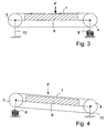
- Figure 3 agrees substantially with fig. 2 but with the difference that the left-hand support 10 in this figure is rigid so that spring movement can only occur at the right-hand support, i.e. the spring 8.
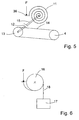
- Figure 4 shows an example in which the floor is slightly inclined (the figure exaggerates the inclination).
- a fixed support 10 and a spring support 8 are provided as in fig. 3.
- An inclined embodiment may also be used with two spring supports as shown in fig. 2.
- the examples in figs. 2-4 show how the floor is vertically movable via spring support at one or both of the roller shafts.
- the spring support may naturally be located directly beneath the actual floor 9 and support this.
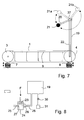
- Figures 5-9 illustrate various examples of how the energy-absorbing device can be realised and how the energy can be stored, if applicable.
- the downward movement of the spring 8 is transmitted via a tension cord to one end of a pendulum 20 provided at one end with a weight 21. Due to lever action the weight is lifted to the position 21a, after which the pendulum is released so that it can swing back and perform a movement up towards the position designated 21b.
- This pendulum movement is in driving connection with a shaft 37 which, via a transmission belt 22, drives the roller 4 for transport of the belt 1.
- Figure 8 illustrates a hydraulic energy-absorbing and energy-storage device.
- the vertical force influences a piston 23 movable in a pump cylinder 24 provided with inlet 25 with non-return valve 27 and outlet 26 with non-return valve 28, so that the movement of the piston pumps liquid from the inlet 25 via the outlet up to a reservoir 29 where its potential energy is stored.
- the reservoir 29 communicates with a hydraulic motor 31 driving the roller 4 of the belt 1 (figs. 2-4).
- An arrangement like that in fig. 8 may alternatively be pneumatic, in which case the container 29 is a compressed air tank and the motor 31 is a pneumatic motor.
- the energy is converted to electricity by a generator consisting of an iron core 32 displaceable by the force F in an induction coil.
- the induced current is stored in an accumulator battery 34 which supplies energy to an electric motor 35 to drive the roller 4.
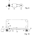
- Figure 10 illustrates an alternative embodiment of the cleaning device for the floor.
- the floor 43 is stationary, but vertically movable.
- the energy is absorbed and stored in one of the ways described above, in a unit 38 arranged to drive a drive roller 39 for a drive chain 40 running over each end of the roller.
- a scraper 41 is arranged at the drive chains 40 and extends at right angles to the plane of the figure. Several such scrapers may be arranged one after the other.
- the drive roller 39 drives the chains 40 in the direction of the arrow, the scraper pushes the waste products in front of it until they are scraped over the edge of the floor (at 42a).
- FIG 11 illustrates an alternative in which the energy obtained when the floor is moved vertically, via the energy-absorbing and energy-storage devices, drives a feeder for straw or fodder 48.
- the feeder may be a worm conveyor 47, for instance.
- the floor 44 may either be stationary or movable, as described above.
- FIG 12 is a block diagram indicating how various functions can be integrated and controlled in an animal keeping device in accordance with the invention.
- 44 represents energy-absorbing means feeding energy to the energy-storage device 45 where these components may be designed in accordance with the examples described above or in some other suitable manner.
- the energy-storage unit supplies energy to drive the various functions 49-52, where 49 may represent a movable floor, 50 a scraper, 51 a fodder supply means and 52 a straw feeder.
- the supply of energy for these functions 49-52 is controlled by a control unit 46 that receives signals from a program in a microprocessor 47 and also from sensors 48.
- control unit opens valves, switches a coupling, releases a back wheel ratchet or closes an electric circuit, depending on the type of the above-exemplified energy-storage principles applied.
- the device illustrated by the block diagram is relatively sophisticated and it should be understood that it may be reduced to varying extents as regards functions and method of control.
Landscapes
- Life Sciences & Earth Sciences (AREA)
- Engineering & Computer Science (AREA)
- Combustion & Propulsion (AREA)
- Environmental Sciences (AREA)
- Chemical & Material Sciences (AREA)
- Biodiversity & Conservation Biology (AREA)
- Zoology (AREA)
- Animal Husbandry (AREA)
- General Engineering & Computer Science (AREA)
- Mechanical Engineering (AREA)
- Housing For Livestock And Birds (AREA)
- Feeding And Watering For Cattle Raising And Animal Husbandry (AREA)
- Peptides Or Proteins (AREA)
- Medicines Containing Material From Animals Or Micro-Organisms (AREA)
- Cleaning In General (AREA)
- Catching Or Destruction (AREA)
- Agricultural Chemicals And Associated Chemicals (AREA)
Claims (14)
- Tierhaltevorrichtung, mit einem Boden (1), einer Versorgungsvorrichtung und mit Antriebsmitteln (4) für die Versorgungsvorrichtung, dadurch gekennzeichnet, dass der Boden (1) zur Aufnahme von Energie vertikal beweglich und mit Energie absorbierenden Mitteln (5) versehen ist, die dazu ausgelegt sind, Energie aufzunehmen, die erzeugt wird, wenn ein Tier (2) aufgrund seiner Bewegung den Boden (1) einer dynamischen Last (F) aussetzt, die eine vertikale Bewegung des Bodens (1) bewirkt, wobei die Energie absorbierenden Mittel (5) dazu ausgelegt sind, die Antriebsmittel (4) mit Energie zu versorgen.
- Tierhaltevorrichtung nach Anspruch 1, dadurch gekennzeichnet, dass die Versorgungsvorrichtung eine Zuführungsvorrichtung (47) zum Zuführen von Futter und/oder Streu (Stroh) (48) aufweist.
- Tierhaltevorrichtung nach Anspruch 1 oder 2, dadurch gekennzeichnet, dass die Versorgungsvorrichtung eine Säuberungsanordnung zum Entfernen von Abfallprodukten wie z.B. Tierabfällen vom Boden aufweist.
- Tierhaltevorrichtung nach Anspruch 2 oder 3, dadurch gekennzeichnet, dass der Boden (1) in Richtung der Bodenebene beweglich ausgelegt ist, und dass der Boden (1) dazu ausgelegt ist, von den Antriebsmitteln (4) angetrieben zu werden.
- Tierhaltevorrichtung nach Anspruch 4, dadurch gekennzeichnet, dass der Boden (1) ein Endlosförderband (1) aufweist und dass die Antriebsmittel (4) eine Antriebsrolle (4) für das Förderband (1) aufweisen.
- Tierhaltevorrichtung nach einem der Ansprüche 1 bis 5, dadurch gekennzeichnet, dass der Boden um eine im Wesentlichen horizontale Achse drehbar ist.
- Tierhaltevorrichtung nach einem der Ansprüche 1 bis 6, dadurch gekennzeichnet, dass der Boden in einem unbelasteten Zustand bezüglich einer horizontalen Ebene geneigt ist.
- Tierhaltevorrichtung nach Anspruch 3, dadurch gekennzeichnet, dass die Säuberungsanordnung einen Kratzer (41) aufweist, der dazu ausgelegt ist, über den Boden bewegt zu werden.
- Tierhaltevorrichtung nach einem der Ansprüche 1 bis 8, dadurch gekennzeichnet, dass die Antriebsmittel dazu ausgelegt sind, intermittierend zu arbeiten.
- Tierhaltevorrichtung nach einem der Ansprüche 1 bis 9, dadurch gekennzeichnet, dass die Energie absorbierenden Mittel (5) Energiespeichermittel (6) aufweisen.
- Tierhaltevorrichtung nach Anspruch 10, dadurch gekennzeichnet, dass die Energiespeichermittel (6) pneumatisch oder hydraulisch (29) sind.
- Tierhaltevorrichtung nach Anspruch 10, dadurch gekennzeichnet, dass die Energiespeichermittel (6) mechanische Speichermittel wie z.B. ein Gewicht (17), ein Pendel (20) oder eine mechanische Feder (7, 8, 11) aufweisen.
- Tierhaltevorrichtung nach Anspruch 10, dadurch gekennzeichnet, dass die Energiespeichermittel (6) einen elektrischen Akkumulator (34) aufweisen.
- Verfahren zur Tierhaltung, dadurch gekennzeichnet, dass die Tiere mit einer Vorrichtung nach einem der Ansprüche 1 bis 13 versorgt werden.
Applications Claiming Priority (3)
| Application Number | Priority Date | Filing Date | Title |
|---|---|---|---|
| SE0100830A SE520871C2 (sv) | 2001-03-12 | 2001-03-12 | Djurhållningsanordning och förfarande vid djurhållning |
| SE0100830 | 2001-03-12 | ||
| PCT/SE2002/000438 WO2002071836A1 (en) | 2001-03-12 | 2002-03-11 | Animal keeping device and a method for animal keeping |
Publications (2)
| Publication Number | Publication Date |
|---|---|
| EP1377158A1 EP1377158A1 (de) | 2004-01-07 |
| EP1377158B1 true EP1377158B1 (de) | 2006-06-21 |
Family
ID=20283299
Family Applications (1)
| Application Number | Title | Priority Date | Filing Date |
|---|---|---|---|
| EP02704015A Expired - Lifetime EP1377158B1 (de) | 2001-03-12 | 2002-03-11 | Tierhaltungsvorrichtung und verfahren zum halten von tieren |
Country Status (14)
| Country | Link |
|---|---|
| US (1) | US7051680B2 (de) |
| EP (1) | EP1377158B1 (de) |
| JP (1) | JP4083020B2 (de) |
| CN (1) | CN1225965C (de) |
| AT (1) | ATE330464T1 (de) |
| CA (1) | CA2440145C (de) |
| DE (1) | DE60212602T2 (de) |
| DK (1) | DK1377158T3 (de) |
| ES (1) | ES2267985T3 (de) |
| NO (1) | NO318412B1 (de) |
| PL (1) | PL212411B1 (de) |
| RU (1) | RU2285392C2 (de) |
| SE (1) | SE520871C2 (de) |
| WO (1) | WO2002071836A1 (de) |
Cited By (1)
| Publication number | Priority date | Publication date | Assignee | Title |
|---|---|---|---|---|
| CN109952969A (zh) * | 2017-12-22 | 2019-07-02 | 苏建忠 | 宠物美仪训练展示台 |
Families Citing this family (34)
| Publication number | Priority date | Publication date | Assignee | Title |
|---|---|---|---|---|
| SE525995C2 (sv) * | 2003-10-16 | 2005-06-07 | Tommy Lindvall | Friktionsdrivanordning för ett transportband och förfarande för drivning |
| US7654229B2 (en) * | 2007-05-18 | 2010-02-02 | Smith Arlan R | Bovine treadmill |
| GB2458161A (en) * | 2008-03-07 | 2009-09-09 | William Taylor | Cattle power generation and feeding arrangement |
| NL1035229C2 (nl) | 2008-03-31 | 2009-10-01 | Lely Patent Nv | Omgeving ingericht voor het houden van dieren. |
| ITBG20080059A1 (it) * | 2008-12-11 | 2010-06-12 | Dionisi Zanchetti | Metodo di realizzazione di una stalla |
| SE536064C2 (sv) * | 2011-09-29 | 2013-04-23 | Tommy Lindvall | Djurhållningsanläggning |
| CN102410161B (zh) * | 2011-10-19 | 2013-10-16 | 谭宜林 | 利用牲畜来发电的发电机组 |
| CN102536696A (zh) * | 2012-02-07 | 2012-07-04 | 马永建 | 骡、马、牛、驴作动力发电 |
| WO2014133442A1 (en) * | 2013-03-01 | 2014-09-04 | Delaval Holding Ab | A manure scraping device |
| CN104115759B (zh) * | 2014-07-11 | 2017-02-08 | 淮安信息职业技术学院 | 一种妊娠猪的智能喂料系统及其工作方法 |
| CN104322387B (zh) * | 2014-09-30 | 2016-02-10 | 宁波江东科海运拓机械科技有限公司 | 一种种公猪跑步机 |
| CN105638501B (zh) * | 2014-09-30 | 2018-05-04 | 华南农业大学 | 一种种公猪跑步机 |
| CN104381143B (zh) * | 2014-09-30 | 2016-06-08 | 余丽 | 一种室内马驹运动机控制方法 |
| SE540573C2 (sv) | 2015-07-08 | 2018-10-02 | Lindvalls Patentbolag Ab | Matta till ett djurhållningsgolv, ett golv samt en djurhållningsanläggning |
| US12239094B2 (en) * | 2015-11-04 | 2025-03-04 | Brilliant Pet 2, Llc | Pet waste apparatus, method and system for user control |
| US12356954B2 (en) | 2015-11-04 | 2025-07-15 | Brilliant Pet 2 LLC | Pet waste roll assembly |
| ES2900800T3 (es) | 2016-01-13 | 2022-03-18 | Big Dutchman Int Gmbh | Establo, en particular para la cría de cerdos |
| CN106234232B (zh) * | 2016-08-04 | 2018-12-07 | 贵州民康生态牧业有限公司 | 一种适于山羊养殖的羊舍 |
| SE543538C2 (sv) * | 2016-09-15 | 2021-03-23 | Lindvalls Patentbolag Ab | Avskrapare för ett ändlöst, rörligt djurhållningsgolv |
| CN106718992B (zh) * | 2017-01-07 | 2019-11-08 | 林勇翔 | 一种促进猪减肥并增强猪肉口感的养猪圈 |
| CN106719050B (zh) * | 2017-03-27 | 2020-11-10 | 山东新希望六和集团有限公司 | 一种牛皮蝇防治清理装置 |
| CN107750982A (zh) * | 2017-10-19 | 2018-03-06 | 绥阳县沐心园生态农业发展有限公司 | 一种母猪定位栏 |
| CN109695552A (zh) * | 2017-12-15 | 2019-04-30 | 黄得锋 | 一种蓄能机构及其应用 |
| CN108150622A (zh) * | 2017-12-15 | 2018-06-12 | 黄得锋 | 一种蓄能机构及其应用 |
| CN108157223B (zh) * | 2017-12-25 | 2020-11-17 | 中科稀土(长春)有限责任公司 | 一种用于养殖动物的设备 |
| JP6444550B1 (ja) * | 2018-01-16 | 2018-12-26 | 弘享 東原 | ペット用トイレ |
| CN108770703A (zh) * | 2018-03-30 | 2018-11-09 | 党艳萍 | 一种自动清洁并带床垫的牛床 |
| CN108849554A (zh) * | 2018-06-27 | 2018-11-23 | 桐梓县聚民富农农业专业合作社 | 养牛厂粪便自动清洁装置 |
| MX2019012441A (es) | 2018-10-22 | 2020-07-14 | Big Dutchman Int Gmbh | Dispositivo separador para reducir emisiones en corrales y corral. |
| CN110141936A (zh) * | 2019-05-28 | 2019-08-20 | 台州创兴环保科技有限公司 | 一种养殖用空气净化设备 |
| US12171187B2 (en) * | 2019-09-10 | 2024-12-24 | Perdue Foods Llc | Drive system for a poultry and/or swine enclosure |
| CN111657155A (zh) * | 2020-06-15 | 2020-09-15 | 内蒙古农业大学 | 一种循环农牧业废弃物预处理管系统 |
| CN113396826B (zh) * | 2021-07-07 | 2023-12-08 | 安徽五祥畜牧科技有限公司 | 一种动物疫病防控用养殖装置 |
| CN114009346A (zh) * | 2021-10-20 | 2022-02-08 | 四川省畜牧科学研究院 | 一种兔养殖清洁装置、系统及清洁方法 |
Family Cites Families (12)
| Publication number | Priority date | Publication date | Assignee | Title |
|---|---|---|---|---|
| US4361115A (en) * | 1980-11-17 | 1982-11-30 | Pike Wendell A | Horse exerciser |
| NL8101597A (nl) * | 1981-03-31 | 1982-10-18 | Johannes Martinus Willibrordus | Voederhok. |
| FR2565065B1 (fr) * | 1984-06-04 | 1986-10-17 | Fullwood Bland Ltd Rj | Stalle de traite et d'alimentation pour ovins et caprins |
| EP0194730A1 (de) * | 1985-03-12 | 1986-09-17 | C. van der Lely N.V. | Gerät zum Melken von Tieren in einem Stall |
| SU1456069A1 (ru) * | 1986-12-11 | 1989-02-07 | Кабардино-Балкарский Агромелиоративный Институт | Станок дл моциона животных |
| SU1607750A1 (ru) * | 1988-02-03 | 1990-11-23 | Научно-производственное объединение по селекционной технике | Станок дл животных |
| SU1535483A1 (ru) * | 1988-04-11 | 1990-01-15 | Алтайский научно-исследовательский и проектно-технологический институт животноводства | Устройство дл содержани животных |
| SU1667760A1 (ru) * | 1989-02-27 | 1991-08-07 | Ю.М.Попов | Устройство дл удалени экскрементов животных |
| RU1797798C (ru) * | 1990-05-25 | 1993-02-28 | Научно-Производственное Объединение "Подмосковье" Отделения Васхнил По Нечерноземной Зоне | Устройство дл моциона животных |
| US5100127A (en) * | 1990-06-18 | 1992-03-31 | Melnick Dennis M | Physical exercise treadmill for quadrupeds |
| RU2038764C1 (ru) * | 1992-03-24 | 1995-07-09 | Кудашкин Юрий Леонидович | Устройство для удаления навоза из стойл |
| NL1001336C1 (nl) | 1995-02-24 | 1996-08-28 | Maasland Nv | Constructie met een inrichting voor het melken van dieren. |
-
2001
- 2001-03-12 SE SE0100830A patent/SE520871C2/sv unknown
-
2002
- 2002-03-11 US US10/471,418 patent/US7051680B2/en not_active Expired - Lifetime
- 2002-03-11 JP JP2002570808A patent/JP4083020B2/ja not_active Expired - Lifetime
- 2002-03-11 EP EP02704015A patent/EP1377158B1/de not_active Expired - Lifetime
- 2002-03-11 DE DE60212602T patent/DE60212602T2/de not_active Expired - Lifetime
- 2002-03-11 CA CA2440145A patent/CA2440145C/en not_active Expired - Lifetime
- 2002-03-11 PL PL362572A patent/PL212411B1/pl unknown
- 2002-03-11 AT AT02704015T patent/ATE330464T1/de active
- 2002-03-11 RU RU2003127738/12A patent/RU2285392C2/ru active
- 2002-03-11 WO PCT/SE2002/000438 patent/WO2002071836A1/en not_active Ceased
- 2002-03-11 DK DK02704015T patent/DK1377158T3/da active
- 2002-03-11 ES ES02704015T patent/ES2267985T3/es not_active Expired - Lifetime
- 2002-03-11 CN CNB028062531A patent/CN1225965C/zh not_active Expired - Lifetime
-
2003
- 2003-09-11 NO NO20034012A patent/NO318412B1/no not_active IP Right Cessation
Cited By (1)
| Publication number | Priority date | Publication date | Assignee | Title |
|---|---|---|---|---|
| CN109952969A (zh) * | 2017-12-22 | 2019-07-02 | 苏建忠 | 宠物美仪训练展示台 |
Also Published As
| Publication number | Publication date |
|---|---|
| DE60212602D1 (de) | 2006-08-03 |
| ES2267985T3 (es) | 2007-03-16 |
| RU2285392C2 (ru) | 2006-10-20 |
| WO2002071836A1 (en) | 2002-09-19 |
| NO20034012D0 (no) | 2003-09-11 |
| US7051680B2 (en) | 2006-05-30 |
| CA2440145A1 (en) | 2002-09-19 |
| CN1496223A (zh) | 2004-05-12 |
| NO318412B1 (no) | 2005-03-14 |
| DE60212602T2 (de) | 2007-05-24 |
| JP4083020B2 (ja) | 2008-04-30 |
| CN1225965C (zh) | 2005-11-09 |
| ATE330464T1 (de) | 2006-07-15 |
| PL362572A1 (en) | 2004-11-02 |
| PL212411B1 (pl) | 2012-09-28 |
| SE0100830D0 (sv) | 2001-03-12 |
| DK1377158T3 (da) | 2006-10-02 |
| SE0100830L (sv) | 2002-09-13 |
| SE520871C2 (sv) | 2003-09-09 |
| JP2004521626A (ja) | 2004-07-22 |
| CA2440145C (en) | 2010-06-22 |
| EP1377158A1 (de) | 2004-01-07 |
| NO20034012L (no) | 2003-11-10 |
| US20040134445A1 (en) | 2004-07-15 |
Similar Documents
| Publication | Publication Date | Title |
|---|---|---|
| EP1377158B1 (de) | Tierhaltungsvorrichtung und verfahren zum halten von tieren | |
| US8651053B2 (en) | Gravity fed automatic rotary vein dispenser | |
| ATE227068T1 (de) | Landwirtschaftliche rundballenpresse mit einer wägeeinrichtung | |
| RU2003127738A (ru) | Устройство для содержания животных и способ содержания животных | |
| EP0547719A1 (de) | Verschiebbares Fütterungsgitter | |
| US5758600A (en) | Livestock dung-collector | |
| CN118901593B (zh) | 一种自适应干清粪集料装置及干清粪车 | |
| US2779309A (en) | Dairy stable sanitation equipment | |
| KR102737702B1 (ko) | 가축 분뇨청소로봇 | |
| US20220386560A1 (en) | Apparatus for the distribution of animal bedding material and/or feedstuff | |
| US3522876A (en) | Conveyor system | |
| CN211211005U (zh) | 一种龙虾养殖自动喂食装置 | |
| CN111657178A (zh) | 一种用于养殖场的饲料自动投喂装置 | |
| RU220439U1 (ru) | Подталкиватель кормов повышенной мобильности с активным шнекоротором | |
| US20110293393A1 (en) | Hay bale transport device | |
| CN213802046U (zh) | 一种畜牧养殖粪便电化学处理输送装置 | |
| RU63255U1 (ru) | Установка перегрузо-сортировочная | |
| CN216376115U (zh) | 一种笼养鸭自动出鸭设备 | |
| CN211607798U (zh) | 一种养猪场用牲畜喂料装置 | |
| GB2171592A (en) | Bale shredding apparatus | |
| CN208377202U (zh) | 一种奶牛饲料分装装置 | |
| CN203975616U (zh) | 饲料秸秆给入机 | |
| KR20150144110A (ko) | 베일러용 이중 바퀴구조 | |
| RU1818031C (ru) | Кормораздатчик | |
| EP2340708A1 (de) | Geflügelsammeleinrichtung |
Legal Events
| Date | Code | Title | Description |
|---|---|---|---|
| PUAI | Public reference made under article 153(3) epc to a published international application that has entered the european phase |
Free format text: ORIGINAL CODE: 0009012 |
|
| 17P | Request for examination filed |
Effective date: 20031013 |
|
| AK | Designated contracting states |
Kind code of ref document: A1 Designated state(s): AT BE CH CY DE DK ES FI FR GB GR IE IT LI LU MC NL PT SE TR |
|
| AX | Request for extension of the european patent |
Extension state: AL LT LV MK RO SI |
|
| GRAP | Despatch of communication of intention to grant a patent |
Free format text: ORIGINAL CODE: EPIDOSNIGR1 |
|
| GRAS | Grant fee paid |
Free format text: ORIGINAL CODE: EPIDOSNIGR3 |
|
| GRAA | (expected) grant |
Free format text: ORIGINAL CODE: 0009210 |
|
| AK | Designated contracting states |
Kind code of ref document: B1 Designated state(s): AT BE CH CY DE DK ES FI FR GB GR IE IT LI LU MC NL PT SE TR |
|
| AX | Request for extension of the european patent |
Extension state: LT LV MK RO SI |
|
| PG25 | Lapsed in a contracting state [announced via postgrant information from national office to epo] |
Ref country code: IT Free format text: LAPSE BECAUSE OF FAILURE TO SUBMIT A TRANSLATION OF THE DESCRIPTION OR TO PAY THE FEE WITHIN THE PRESCRIBED TIME-LIMIT;WARNING: LAPSES OF ITALIAN PATENTS WITH EFFECTIVE DATE BEFORE 2007 MAY HAVE OCCURRED AT ANY TIME BEFORE 2007. THE CORRECT EFFECTIVE DATE MAY BE DIFFERENT FROM THE ONE RECORDED. Effective date: 20060621 |
|
| REG | Reference to a national code |
Ref country code: GB Ref legal event code: FG4D |
|
| REG | Reference to a national code |
Ref country code: CH Ref legal event code: EP |
|
| REG | Reference to a national code |
Ref country code: IE Ref legal event code: FG4D |
|
| REF | Corresponds to: |
Ref document number: 60212602 Country of ref document: DE Date of ref document: 20060803 Kind code of ref document: P |
|
| PG25 | Lapsed in a contracting state [announced via postgrant information from national office to epo] |
Ref country code: SE Free format text: LAPSE BECAUSE OF FAILURE TO SUBMIT A TRANSLATION OF THE DESCRIPTION OR TO PAY THE FEE WITHIN THE PRESCRIBED TIME-LIMIT Effective date: 20060921 |
|
| REG | Reference to a national code |
Ref country code: DK Ref legal event code: T3 |
|
| PG25 | Lapsed in a contracting state [announced via postgrant information from national office to epo] |
Ref country code: PT Free format text: LAPSE BECAUSE OF FAILURE TO SUBMIT A TRANSLATION OF THE DESCRIPTION OR TO PAY THE FEE WITHIN THE PRESCRIBED TIME-LIMIT Effective date: 20061121 |
|
| REG | Reference to a national code |
Ref country code: CH Ref legal event code: NV Representative=s name: BOVARD AG PATENTANWAELTE |
|
| ET | Fr: translation filed | ||
| REG | Reference to a national code |
Ref country code: ES Ref legal event code: FG2A Ref document number: 2267985 Country of ref document: ES Kind code of ref document: T3 |
|
| PLBE | No opposition filed within time limit |
Free format text: ORIGINAL CODE: 0009261 |
|
| STAA | Information on the status of an ep patent application or granted ep patent |
Free format text: STATUS: NO OPPOSITION FILED WITHIN TIME LIMIT |
|
| 26N | No opposition filed |
Effective date: 20070322 |
|
| PG25 | Lapsed in a contracting state [announced via postgrant information from national office to epo] |
Ref country code: MC Free format text: LAPSE BECAUSE OF NON-PAYMENT OF DUE FEES Effective date: 20070331 |
|
| PG25 | Lapsed in a contracting state [announced via postgrant information from national office to epo] |
Ref country code: GR Free format text: LAPSE BECAUSE OF FAILURE TO SUBMIT A TRANSLATION OF THE DESCRIPTION OR TO PAY THE FEE WITHIN THE PRESCRIBED TIME-LIMIT Effective date: 20060922 |
|
| PG25 | Lapsed in a contracting state [announced via postgrant information from national office to epo] |
Ref country code: LU Free format text: LAPSE BECAUSE OF NON-PAYMENT OF DUE FEES Effective date: 20070311 Ref country code: CY Free format text: LAPSE BECAUSE OF FAILURE TO SUBMIT A TRANSLATION OF THE DESCRIPTION OR TO PAY THE FEE WITHIN THE PRESCRIBED TIME-LIMIT Effective date: 20060621 |
|
| PG25 | Lapsed in a contracting state [announced via postgrant information from national office to epo] |
Ref country code: TR Free format text: LAPSE BECAUSE OF FAILURE TO SUBMIT A TRANSLATION OF THE DESCRIPTION OR TO PAY THE FEE WITHIN THE PRESCRIBED TIME-LIMIT Effective date: 20060621 |
|
| REG | Reference to a national code |
Ref country code: CH Ref legal event code: PFA Owner name: LINDVALL, TOMMY Free format text: LINDVALL, TOMMY#KVIE EKEBY#621 70 VISBY (SE) -TRANSFER TO- LINDVALL, TOMMY#KVIE EKEBY#621 70 VISBY (SE) |
|
| REG | Reference to a national code |
Ref country code: FR Ref legal event code: PLFP Year of fee payment: 15 |
|
| REG | Reference to a national code |
Ref country code: FR Ref legal event code: PLFP Year of fee payment: 16 |
|
| PGFP | Annual fee paid to national office [announced via postgrant information from national office to epo] |
Ref country code: CH Payment date: 20170320 Year of fee payment: 16 Ref country code: FI Payment date: 20170320 Year of fee payment: 16 Ref country code: FR Payment date: 20170314 Year of fee payment: 16 |
|
| PGFP | Annual fee paid to national office [announced via postgrant information from national office to epo] |
Ref country code: IE Payment date: 20170320 Year of fee payment: 16 Ref country code: AT Payment date: 20170327 Year of fee payment: 16 Ref country code: GB Payment date: 20170322 Year of fee payment: 16 Ref country code: DK Payment date: 20170323 Year of fee payment: 16 Ref country code: BE Payment date: 20170315 Year of fee payment: 16 |
|
| PGFP | Annual fee paid to national office [announced via postgrant information from national office to epo] |
Ref country code: IT Payment date: 20170321 Year of fee payment: 16 |
|
| PGFP | Annual fee paid to national office [announced via postgrant information from national office to epo] |
Ref country code: ES Payment date: 20170328 Year of fee payment: 16 |
|
| REG | Reference to a national code |
Ref country code: LT Ref legal event code: MM9D Effective date: 20180311 |
|
| REG | Reference to a national code |
Ref country code: DK Ref legal event code: EBP Effective date: 20180331 |
|
| PG25 | Lapsed in a contracting state [announced via postgrant information from national office to epo] |
Ref country code: FI Free format text: LAPSE BECAUSE OF NON-PAYMENT OF DUE FEES Effective date: 20180311 |
|
| REG | Reference to a national code |
Ref country code: CH Ref legal event code: PL |
|
| REG | Reference to a national code |
Ref country code: AT Ref legal event code: MM01 Ref document number: 330464 Country of ref document: AT Kind code of ref document: T Effective date: 20180311 |
|
| GBPC | Gb: european patent ceased through non-payment of renewal fee |
Effective date: 20180311 |
|
| REG | Reference to a national code |
Ref country code: BE Ref legal event code: MM Effective date: 20180331 |
|
| REG | Reference to a national code |
Ref country code: IE Ref legal event code: MM4A |
|
| PG25 | Lapsed in a contracting state [announced via postgrant information from national office to epo] |
Ref country code: IE Free format text: LAPSE BECAUSE OF NON-PAYMENT OF DUE FEES Effective date: 20180311 Ref country code: AT Free format text: LAPSE BECAUSE OF NON-PAYMENT OF DUE FEES Effective date: 20180311 |
|
| PG25 | Lapsed in a contracting state [announced via postgrant information from national office to epo] |
Ref country code: BE Free format text: LAPSE BECAUSE OF NON-PAYMENT OF DUE FEES Effective date: 20180331 Ref country code: IT Free format text: LAPSE BECAUSE OF NON-PAYMENT OF DUE FEES Effective date: 20180311 Ref country code: GB Free format text: LAPSE BECAUSE OF NON-PAYMENT OF DUE FEES Effective date: 20180311 Ref country code: CH Free format text: LAPSE BECAUSE OF NON-PAYMENT OF DUE FEES Effective date: 20180331 Ref country code: LI Free format text: LAPSE BECAUSE OF NON-PAYMENT OF DUE FEES Effective date: 20180331 |
|
| PG25 | Lapsed in a contracting state [announced via postgrant information from national office to epo] |
Ref country code: FR Free format text: LAPSE BECAUSE OF NON-PAYMENT OF DUE FEES Effective date: 20180331 |
|
| PG25 | Lapsed in a contracting state [announced via postgrant information from national office to epo] |
Ref country code: DK Free format text: LAPSE BECAUSE OF NON-PAYMENT OF DUE FEES Effective date: 20180331 |
|
| REG | Reference to a national code |
Ref country code: ES Ref legal event code: FD2A Effective date: 20190904 |
|
| PG25 | Lapsed in a contracting state [announced via postgrant information from national office to epo] |
Ref country code: ES Free format text: LAPSE BECAUSE OF NON-PAYMENT OF DUE FEES Effective date: 20180312 |
|
| PGFP | Annual fee paid to national office [announced via postgrant information from national office to epo] |
Ref country code: NL Payment date: 20210318 Year of fee payment: 20 |
|
| PGFP | Annual fee paid to national office [announced via postgrant information from national office to epo] |
Ref country code: DE Payment date: 20210319 Year of fee payment: 20 |
|
| REG | Reference to a national code |
Ref country code: DE Ref legal event code: R071 Ref document number: 60212602 Country of ref document: DE |
|
| REG | Reference to a national code |
Ref country code: NL Ref legal event code: MK Effective date: 20220310 |