EP1376927B1 - Data projection system and method - Google Patents
Data projection system and method Download PDFInfo
- Publication number
- EP1376927B1 EP1376927B1 EP03013281A EP03013281A EP1376927B1 EP 1376927 B1 EP1376927 B1 EP 1376927B1 EP 03013281 A EP03013281 A EP 03013281A EP 03013281 A EP03013281 A EP 03013281A EP 1376927 B1 EP1376927 B1 EP 1376927B1
- Authority
- EP
- European Patent Office
- Prior art keywords
- projector
- computing device
- data
- connection
- remote
- Prior art date
- Legal status (The legal status is an assumption and is not a legal conclusion. Google has not performed a legal analysis and makes no representation as to the accuracy of the status listed.)
- Expired - Lifetime
Links
- 238000000034 method Methods 0.000 title claims abstract description 27
- 230000000007 visual effect Effects 0.000 claims abstract description 3
- 238000004891 communication Methods 0.000 claims description 17
- 230000004044 response Effects 0.000 claims description 2
- 238000004590 computer program Methods 0.000 claims 6
- 230000003362 replicative effect Effects 0.000 claims 1
- 239000000463 material Substances 0.000 abstract description 9
- 238000005516 engineering process Methods 0.000 description 8
- 230000006855 networking Effects 0.000 description 6
- 230000003287 optical effect Effects 0.000 description 6
- 238000012545 processing Methods 0.000 description 6
- 230000007246 mechanism Effects 0.000 description 5
- 238000012546 transfer Methods 0.000 description 5
- 230000008901 benefit Effects 0.000 description 4
- 230000002093 peripheral effect Effects 0.000 description 4
- 230000009471 action Effects 0.000 description 3
- 238000010586 diagram Methods 0.000 description 3
- 230000005055 memory storage Effects 0.000 description 3
- 230000000694 effects Effects 0.000 description 2
- 230000006870 function Effects 0.000 description 2
- 230000003993 interaction Effects 0.000 description 2
- 239000007787 solid Substances 0.000 description 2
- CDFKCKUONRRKJD-UHFFFAOYSA-N 1-(3-chlorophenoxy)-3-[2-[[3-(3-chlorophenoxy)-2-hydroxypropyl]amino]ethylamino]propan-2-ol;methanesulfonic acid Chemical compound CS(O)(=O)=O.CS(O)(=O)=O.C=1C=CC(Cl)=CC=1OCC(O)CNCCNCC(O)COC1=CC=CC(Cl)=C1 CDFKCKUONRRKJD-UHFFFAOYSA-N 0.000 description 1
- 108700026836 CAPABLE protocol Proteins 0.000 description 1
- 230000006399 behavior Effects 0.000 description 1
- 230000009286 beneficial effect Effects 0.000 description 1
- 238000012508 change request Methods 0.000 description 1
- 230000003247 decreasing effect Effects 0.000 description 1
- 230000007812 deficiency Effects 0.000 description 1
- 230000001419 dependent effect Effects 0.000 description 1
- JLYFCTQDENRSOL-VIFPVBQESA-N dimethenamid-P Chemical compound COC[C@H](C)N(C(=O)CCl)C=1C(C)=CSC=1C JLYFCTQDENRSOL-VIFPVBQESA-N 0.000 description 1
- 230000009977 dual effect Effects 0.000 description 1
- 238000011156 evaluation Methods 0.000 description 1
- 230000004438 eyesight Effects 0.000 description 1
- 230000006872 improvement Effects 0.000 description 1
- 238000009434 installation Methods 0.000 description 1
- 238000007726 management method Methods 0.000 description 1
- 230000008569 process Effects 0.000 description 1
- 230000001052 transient effect Effects 0.000 description 1
- 230000007723 transport mechanism Effects 0.000 description 1
Images

Classifications
-
- H—ELECTRICITY
- H04—ELECTRIC COMMUNICATION TECHNIQUE
- H04L—TRANSMISSION OF DIGITAL INFORMATION, e.g. TELEGRAPHIC COMMUNICATION
- H04L67/00—Network arrangements or protocols for supporting network services or applications
- H04L67/01—Protocols
- H04L67/08—Protocols specially adapted for terminal emulation, e.g. Telnet
-
- H—ELECTRICITY
- H04—ELECTRIC COMMUNICATION TECHNIQUE
- H04L—TRANSMISSION OF DIGITAL INFORMATION, e.g. TELEGRAPHIC COMMUNICATION
- H04L9/00—Cryptographic mechanisms or cryptographic arrangements for secret or secure communications; Network security protocols
- H04L9/40—Network security protocols
-
- H—ELECTRICITY
- H04—ELECTRIC COMMUNICATION TECHNIQUE
- H04L—TRANSMISSION OF DIGITAL INFORMATION, e.g. TELEGRAPHIC COMMUNICATION
- H04L69/00—Network arrangements, protocols or services independent of the application payload and not provided for in the other groups of this subclass
- H04L69/30—Definitions, standards or architectural aspects of layered protocol stacks
- H04L69/32—Architecture of open systems interconnection [OSI] 7-layer type protocol stacks, e.g. the interfaces between the data link level and the physical level
- H04L69/322—Intralayer communication protocols among peer entities or protocol data unit [PDU] definitions
- H04L69/329—Intralayer communication protocols among peer entities or protocol data unit [PDU] definitions in the application layer [OSI layer 7]
Definitions
- This invention relates generally to the technology of information sharing and, more particularly, relates to a system and method for simplified information projection to a projector or other device or devices.
- a system and method of conferencing presentation are needed whereby set up of a conferencing presentation is simplified and whereby control and transfer of presentation management can occur with decreased complexity and improved speed.
- US 2002/029256 A1 describes a technology to dynamically connect distributed devices and services.
- a device makes itself known and available for communication with other entities on a computing network so that user installation experience can be avoided.
- This open network architecture is called Universal Plug and Play (UPnP), and includes user control points which initiate discovery and communication with controlled devices and receive events from controlled devices.
- a user control point is typically implemented on a device having a user interface.
- a controlled device (UPnP device) provides a description document which describes the capabilities of the device. After retrieving the description document, a control point is able to control the device and therefore sends an action request to the device's service. In response, the service of the device provides a simple acknowledgement and further allows the control point to request a certain action.
- a UPnP device has a presentation page which can be loaded into a browser and allows a user to control the device and/or view device status.
- a terminal server offers the possibility of thin-client computing for multiple users having remote access to the server.
- the system is divided into a terminal server and different terminal clients communicating with a remote display protocol.
- the communication includes control messages, for example keystrokes or mouse events, sent from the clients to the server and display messages sent from the server to the clients.
- a novel system and method are described for increasing the effectiveness and simplicity of information projection.
- the scenarios enabled involve the automatic connection of a presenter's device to a projection screen or other projection target. Rather than being required to find and connect various wires and cables in order to make a presentation, the presenter simply walks into a room, whereupon his or her laptop computer or other device discovers and connects to the desired projection target, such as a conference room projector, with minimal effort on the part of the presenter.
- a reverse terminal server model is utilized to establish a connection from a presentation server, or projection device, to a presentation client, or projection target.
- the discovery by the projection device of the projection target is by way of the Universal Plug and Play protocol.
- a terminal services session is commenced via the reverse terminal server model to enable the exchange of screen data and/or other data between the projection device and the projection target.
- shadowing is used to provide the display on the terminal services server while the terminal services client renders the information for presentation.
- program modules include routines, programs, objects, components, data structures, etc. that perform particular tasks or implement particular abstract data types.
- program modules include routines, programs, objects, components, data structures, etc. that perform particular tasks or implement particular abstract data types.
- program modules may be practiced with other computer system configurations, including hand-held devices, multiprocessor systems, microprocessor based or programmable consumer electronics, network PCs, minicomputers, mainframe computers, and the like.
- the invention is primarily for use in a networked environment and may further be practiced in distributed computing environments where tasks are performed by remote processing devices that are linked through a communications network.
- program modules may be located in both local and remote memory storage devices.
- FIG. 1 illustrates an example of a suitable computing system environment 100 usable in an implementation of the invention, and according to which either or both of a projection device and a projection target device may operate.
- the computing system environment 100 is only one example of a suitable computing environment and is not intended to suggest any limitation as to the scope of use or functionality of the invention. Neither should the computing environment 100 be interpreted as having any dependency or requirement relating to any one or combination of components illustrated in the exemplary operating environment 100.
- the term "projector” includes, but is not limited to, any group display mechanism with wireless capability. It is not required that the projector comprise a wireless interface, since, for example, in some embodiments of the invention the projector may be physically wired to an infrastructure.
- the invention may be implemented by way of numerous other general purpose or special purpose computing system environments or configurations.
- Examples of well known computing systems, environments, and/or configurations that are suitable for use with the invention include, but are not limited to, personal computers, server computers, hand-held or laptop devices, multiprocessor systems, microprocessor-based systems, set top boxes, programmable consumer electronics, network PCs, minicomputers, mainframe computers, distributed computing environments that include any of the above systems or devices, and the like.
- An exemplary system for implementing the invention includes a general-purpose computing device in the form of a computer 110.
- Components of the computer 110 generally include, but are not limited to, a processing unit 120, a system memory 130, and a system bus 121 that couples various system components including the system memory to the processing unit 120.
- the system bus 121 may be any of several types of bus structures including a memory bus or memory controller, a peripheral bus, and a local bus using any of a variety of bus architectures.
- such architectures include Industry Standard Architecture (ISA) bus, Micro Channel Architecture (MCA) bus, Enhanced ISA (EISA) bus, Video Electronics Standards Associate (VESA) local bus, and Peripheral Component Interconnect (PCI) bus also known as Mezzanine bus.
- ISA Industry Standard Architecture
- MCA Micro Channel Architecture
- EISA Enhanced ISA
- VESA Video Electronics Standards Associate
- PCI Peripheral Component Interconnect
- Computer 110 typically includes a variety of computer readable media.
- Computer readable media can be any available media that can be accessed by computer 110 and includes both volatile and nonvolatile media, removable and non-removable media.
- Computer readable media may comprise computer storage media and communication media.
- Computer storage media includes volatile and nonvolatile, removable and non-removable media implemented in any method or technology for storage of information such as computer readable instructions, data structures, program modules or other data.
- Computer storage media includes, but is not limited to, RAM, ROM, EEPROM, flash memory or other memory technology, CD-ROM, digital versatile disks (DVD) or other optical disk storage, magnetic cassettes, magnetic tape, magnetic disk storage or other magnetic storage devices, or any other medium which can be used to store the desired information and which can be accessed by computer 110.
- Communication media typically embodies computer readable instructions, data structures, program modules or other data in a modulated data signal such as a carrier wave or other transport mechanism and includes any information delivery media.
- modulated data signal means a signal that has one or more of its characteristics (such as, for example, voltage or current level, voltage or current pulse existence or nonexistence, voltage or current pulse width, voltage or current pulse spacing, etc.) set or changed in such a manner as to encode information in the signal.
- communication media includes wired media such as a wired network or direct-wired connection, and wireless media such as acoustic, RF, infrared and other wireless media. Combinations of any of the above are also included within the scope of computer readable media.
- the system memory 130 includes computer storage media in the form of volatile and/or nonvolatile memory such as read only memory (ROM) 131 and random access memory (RAM) 132.
- ROM read only memory
- RAM random access memory
- BIOS basic input/output system
- RAM 132 typically contains data and/or program modules that are immediately accessible to and/or presently being operated on by processing unit 120.
- Figure 1 illustrates RAM 132 as containing operating system 134, application programs 135, other program modules 136, and program data 137.
- the computer 110 may also include other removable/non-removable, volatile/nonvolatile computer storage media.
- Figure 1 illustrates a hard disk drive 141 that reads from or writes to non-removable, nonvolatile magnetic media, a magnetic disk drive 151 that reads from or writes to a removable, nonvolatile magnetic disk 152, and an optical disk drive 155 that reads from or writes to a removable, nonvolatile optical disk 156 such as a CD-ROM or other optical media.
- removable/non-removable, volatile/nonvolatile computer storage media that can be used in the exemplary operating environment include, but are not limited to, magnetic tape cassettes, flash memory cards, digital versatile disks, digital video tape, solid state RAM, solid state ROM, and the like.
- the hard disk drive 141 is typically connected to the system bus 121 through a non-removable memory interface such as interface 140, and magnetic disk drive 151 and optical disk drive 155 are typically connected to the system bus 121 by a removable memory interface, such as interface 150.
- hard disk drive 141 is illustrated as storing operating system 144, application programs 145, other program modules 146, and program data 147. Note that these components can either be the same as or different from operating system 134, application programs 135, other program modules 136, and program data 137. Operating system 144, application programs 145, other program modules 146, and program data 147 are given different numbers herein to illustrate that, at a minimum, they are different copies.
- a user may enter commands and information into the computer 110 through input devices such as a keyboard 162, pointing device 161 (commonly referred to as a mouse), and trackball or touch pad.
- Other input devices may include a microphone, joystick, game pad, satellite dish, scanner, or the like.
- a dedicated monitor 191 or other type of display device may also be connected to the system bus 121 via an interface, such as a video interface 190.
- computer 110 may also include other peripheral output devices such as speakers 197 and printer 196, which may be connected through an output peripheral interface 195.
- the computer 110 operates in a networked environment using logical connections to one or more remote computers, such as a remote computer 180.
- the remote computer 180 may be a personal computer, a router, a network PC, a peer device or other common network node, or a dedicated projection target device such as an electronic projection screen or monitor, and in any case the remote computer or computers typically include many or all of the elements described above relative to the personal computer 110, although only a memory storage device 181 has been illustrated in Figure 1 , and although in some cases the remote computer can lack much of the functionality contained in the computer 110.
- the logical connections depicted in Figure 1 include a local area network (LAN) 171 and a wide area network (WAN) 173, but the computer 110 may additionally or alternatively use one or more other networking environments.
- the computer 110 may reside on an ad hoc network via a communications interface such as a wireless interface.
- LAN local area network
- WAN wide area network
- Networking environments of all types are commonplace in offices, enterprise-wide computer networks, intranets and the Internet.
- the computer 110 should include facilities for accessing the networks to which it is attachable.
- the personal computer 110 when used in a LAN networking environment, the personal computer 110 is connected to the LAN 171 through a network interface or adapter 170.
- Another node on the LAN such as a proxy server, may be further connected to a WAN such as the Internet.
- the computer 110 When used in a WAN networking environment, the computer 110 typically includes a modem 172 or other means for establishing communications directly or indirectly over the WAN 173, such as the Internet.
- the modem 172 which may be internal or external, may be connected to the system bus 121 via the user input interface 160, or other appropriate mechanism.
- wireless network interfacing be it to a LAN, WAN, ad hoc network, or other network type, will allow the greatest freedom to reap the benefits of the invention, although the invention also contemplates the use of more traditional hard wired interfaces.
- FIG. 1 illustrates remote application programs 185 as residing on memory device 181.
- the network connections shown are exemplary and other means of establishing a communications link between the computers may be used. It is not intended to limit the invention to use in a permanent network infrastructure, since it may also be used in transiently connected environments, such as for example a wholly or partially wireless network environment interconnected wholly or partially via optical, infrared, and/or radio frequency wireless connections.
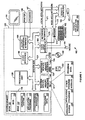
- FIG. 2A illustrates schematically a networking environment within which the present invention may be implemented.
- the network environment shown in the figure includes a projection device 201, which may be any computing device such as, for example, those described above in reference to Figure 1 , for projecting information to one or more projection target devices 203, 205, 207, and 209.
- Projection target devices 203-207 are illustrated as non-dedicated computing devices similar to the projection device 201.
- the devices 201-207 may be, by way of example and not limitation, laptop computers, desktop computers, handheld computing devices, any other multi-purpose computing devices, or any combination of these types of devices.
- a projection target device need not be a traditional computing device, and may be for example a television system.
- Network 211 is usable to transfer information between the target devices 203-207 and the projection device 201.
- the projection targets may additionally or alternatively include a dedicated projection device such as an electronic conference room projector or display device 209.
- the target device 209 preferably communicates with the projection device 201 via network 211.
- Network 211 may be any type of network, but will typically comprise wireless interfaces between the projecting device 201 and the network 211, and between the network 211 and the projection targets 203-207.
- the interface between the network 211 and the dedicated projection device 209 may desirably be either wired or wireless.
- the dedicated projection device 209 can remain in a particular location, such as a conference room, for a long period of time, there is no significant decrease in device utility by having a wired interface from the device 209 to the network 211.
- the network 211 itself will generally, although not necessarily, be a wired infrastructure such as a corporate LAN, a WAN, or other traditional wholly or partially wired network.
- FIG. 2B An alternative network environment is shown schematically in Figure 2B .
- projection device 201 and projection targets 203-209 are interconnected via an ad hoc wireless network consisting of wireless links 213-225.
- ad hoc wireless network consisting of wireless links 213-225.
- connections 213-225 are necessary since an ad hoc network does not require direct connection of every node to every other node.
- a node may be connected to all nodes of the ad hoc network indirectly via a single connection to another node.
- ad hoc topologies include rings, lines, webs, hub-and-spokes, and/or other topologies as needed.
- the physical distance of a particular device from other devices will determine to which device or devices, if any, of the ad hoc network the particular device connects directly.
- the projection device 201 is in the possession of a presenting individual wishing to project material of interest to receiving individuals, typically in a conference room or meeting room setting, although the inventive system is also usable in non-business settings, such as in a home environment, as well.
- the material of interest may be graphical, such as images or video, or textual such as in a document, chart etc., and may also include audio elements.
- the material of interest is entirely audio information.
- the material of interest need not be computer-generated, it is preferably accessible to the projection device 201 locally or remotely in a computer-readable format.
- the projection target devices 203-207 may be the laptop computers of the receiving individuals, while the projection target device 209 may be a dedicated projection system, such as a conference room projector or large screen monitor or other display not typically associated physically with any one user, unlike a mobile laptop or handheld device.
- a dedicated projection system such as a conference room projector or large screen monitor or other display not typically associated physically with any one user, unlike a mobile laptop or handheld device.
- the network connectivity between the devices 203-209 typically commences as each device comes into communication range of the projection device 201 associated with the presenting user.
- the dedicated device 209 resides permanently in a conference room.
- a wireless connection either ad hoc or via a network infrastructure, is formed between the dedicated device 209 and the projection device 201.
- the presenting user is then able to project material from his device 201 onto the screen of the dedicated device 209 for the receiving individuals to observe.
- the presenting user has effected a presentation without physically connecting any cables or cords, and can similarly end the presentation, or transfer its control to another presenting individual using another projection device, without disconnecting any cables or cords.
- the presenting user can present material of interest to a number of target devices such as devices 203-207.
- the network connection between the projection device 201 and the target devices 203-207 is automatically executed after automated discovery without requiring the user to locate and manipulate physical connections.
- the presentation of material occurs from the projection device 201 to the screens of the target devices, which may be laptop computers belonging to receiving individuals.
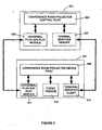
- the projection device 201 architecture comprises a projector control point 303, a Universal Plug and Play component 305, and a terminal services server 307.
- the projector control point 303 is an application that controls the function of the Universal Plug and Play component 305 and the terminal services server 307 to establish and maintain a projection session.
- the projector control point 303 is also responsible for presentation of user interface information to the presenting individual via a display of the device 201.
- Such user interface information preferably comprises a selection window within which the presenting user may view available projection targets and select desired connection targets.
- Other connection information such as time, status, control change requests and so forth may also be presented in the user interface by the projector control point 303.
- the projection target 301 architecture comprises a projector device point 309, a Universal Plug and Play component 311, and a terminal services client 313.
- the projector device point 309 is an application that controls the Universal Plug and Play component 311 and the terminal services client 313 during the set up and utilization of a projection session.
- the Universal Plug and Play component 311 of the projection target 301 cooperates with the Universal Plug and Play component 305 of the projection device 201 to facilitate discovery by the projection device 201 of the projection target 301 in an embodiment of the invention as will be described hereinafter.
- the terminal services client 313 of the projection target 301 cooperates with the terminal services server 307 of the projection device 201 during the projection session to facilitate the exchange of presentation information from the projection device 201 to the projection target 301, as will be described hereinafter in greater detail.
- each of the projection device 201 and the projection target 301 preferably also includes an operating system for controlling the basic operation of the relevant device.
- an operating system for controlling the basic operation of the relevant device.
- suitable operating systems it has been observed that the XP brand operating system and the WINDOWS CE brand operating system, both by MICROSOFT of Redmond, Washington, are ideally suited for use within the invention.
- the projection target 301 can advantageously use the WINDOWS CE brand operating system since the projection target 301 may have both limited computation demands and limited computational resources.
- the projection target 301 architecture also comprises a codec module 315 in an embodiment of the invention.
- the codec module 315 is used to interpret or decode information received by the projection target 301 from the projection device 201 when the received information comprises encoded audio or video information, as will be described in greater detail below with respect to Figure 4 .
- multiple and/or diverse codecs may be used without limitation.
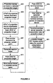
- Figure 4 illustrates in flow chart form the operation of the aforementioned system components during establishment of a projection session, and while the projection session continues in progress.
- a connection should be formed between the projection device 201 and the projection target 301 to the extent such a connection is not already open.
- the projection device 201 forms a connection via an appropriate network interface to the network upon which the projection target 301 resides. If the projection target 301 has not yet connected to the relevant network then it too should connect at this time via an appropriate network interface.
- the network comprises an 802.11 compliant wireless link, operated either in infrastructure mode or as part of an ad hoc network as discussed above.
- the projection device 201 and the projection target 301 are both connected to a common network. Still, each of the projection device 201 and the projection target 301 may remain unaware of the presence of the other as such. If so, then at step 403 the Universal Plug and Play component 305 of the projection device is apprised of the presence of the Universal Plug and Play component 311 of the projection target 301. This step may be carried out either via the standard plug and play announcement mechanism whereby the Universal Plug and Play component 311 of the projection target 301 announces its presence and capabilities to the Universal Plug and Play component 305 of the projection device. Alternatively, the Universal Plug and Play component 305 of the projection device 201 may affirmatively search for and locate the Universal Plug and Play component 311 of the projection target 301.
- Universal Plug and Play will be familiar to those of skill in the art, a brief overview is provided herein for the convenience of the reader. The reader is invited to consult published standards information for further information if desired. Universal Plug and Play refers to a standardized set of methods for device interaction.
- UPnP allows peer-to-peer connectivity of intelligent devices, appliances, and so on.
- UPnP is applicable within managed, unmanaged, and ad hoc networks.
- UPnP employs existing TCP/IP and Internet technologies to provide for the exchange of control information and data between networked devices.
- UPnP networking is designed to be independent of the particular network medium or media being used.
- the UPnP control point typically exposes a set of COM (Component Object Model) interfaces through which applications may find and control the host device.
- Applications use device objects to retrieve information or properties pertaining to the host device.
- Such information can include, among other information, device hierarchy information, device properties, device manufacturer information, device model information, device display information, and services provided by the device.
- the UPnP control point need not be a COM entity, although such is discussed herein for purposes of explication.
- UPnP-enabled devices can be controlled by way of the services they expose, there typically being one service for every primary function that the device can perform.
- a complex device may be represented by some simple services in addition to other nested devices.
- a service typically comprises a set of state variables and a set of actions that an application may invoke to operate on one or more variables in the set of state variables. Services are identified by a service type as well as a service ID.
- the UPnP component 305 of the projection device downloads a UPnP service document advertised by the UPnP component 311 of the projection target 301 in step 405.
- a service document is a computer-parsable document typically containing a description of commands that the associated device will recognize as well as perhaps some other basic device information such as proper name, number of interfaces, etc.
- the service document comprises, in addition to other information, a description of the device resolution, color depth, a current control point, a current state, as well as brightness, contrast, and tint values.
- the retrieved service document is passed to the projector control point 303 of the projection device 201. In this manner, the projector control point 303 is able to enumerate the services that the projection target 301 provides.
- the projection device 201 is aware of the existence and capabilities of the projection target 301 via the UPnP exchange, and a projection session may be connected.
- a unique reverse terminal server connection technique is followed to create the presentation data exchange connection for the projection session.
- the projector control point 303 of the projection device 201 generates a session ticket for its terminal services server 307.
- the session ticket is preferably generated in coordination with the Remote Desktop Protocol (RDP).
- RDP is a multichannel capable protocol that is an extension of the T.120 family of protocol standards.
- the protocol supports a plurality of virtual channels, each for exchanging a particular type of information, such as presentation data, input data and so forth.
- RDP maintains a stack (for the terminal services client or server) that is similar to the stack prescribed by the OSI seven-layer model.
- data to be transmitted from the server is processed downward through the protocol stack, sectioned, sent to an appropriate channel, encrypted if appropriate, wrapped, framed, packetized according to a network protocol, addressed, and transmitted to the client.
- the generated ticket presents information regarding how the projection target 301 should connect (via the terminal services client 313 of the projection target 301) to the projector control point 303 of the projection device 201, as well as in what mode to connect.
- the connection mode may be specified as a projection mode, extended desktop mode, a mode for display of a particular application's screen information, etc.
- the generated ticket is given an unusually limited time out period such as, for example, ten seconds, in order to provide for a more secure connection process between the projection device 201 and the projection target 301.
- an embodiment of the invention is described herein by way of RDP, use of RDP is not required in every embodiment, as other technologies such as HTML may alternatively be used.
- step 411 the generated ticket is passed to the projection target 301 via its UPnP component 311 from the UPnP component 305 of the projection device 201.
- the ticket information can be used by the projector device point 309 to connect a terminal services session.
- the UPnP component 311 of the projection target 301 passes the received ticket to the projector device point 309 at step 413.
- the projector device point 309 then passes the ticket to the terminal services client 313 at step 415.
- the terminal services client 313 of the projection target 301 uses the ticket in step 417 to establish a connection back to the terminal services server 307 of the projection device 201.
- this connection is timed so that it will time out if it remains inactive for longer than a predetermined period of time, such as ten minutes. In this manner, a projection device user will not be able to inadvertently monopolize the projection target, such as by walking away without closing the connection, when another user could be waiting to use the target.
- the terminal services server 307 of the projection device 201 transmits presentation data such as screen data from the screen of the projection device 201 to the projection target 301 via the connection.
- the data transmitted at step 419 or subsequently may consist of or comprise audio and or video information.
- This information is preferably encoded to conserve bandwidth, and as such the codec module 315 of the projection target is used to decode the information.
- the audio and/or video information of interest may not be played at the projection device 201 itself but rather only at the projection target 301. In this manner, copyright restrictions regarding numbers of licensed users may be adhered to when present. Similarly for text or other non-video visual information, copyright restrictions should be respected where appropriate by restricting the number of screens upon which, or users to which, the relevant information is displayed. It is also contemplated, but less desirable, to transmit audio and/or video information from the projection device 201 to the projection target 301 in unencoded form.
- the projection target 301 renders and/or plays the received information as appropriate via a display screen, speakers, etc. as needed.
- Certain technologies usable to implement embodiments of the invention such as Terminal Services by MICROSOFT of Redmond, Washington, do not automatically allow display of information simultaneously on both a terminal client screen and a terminal server screen. In such cases, shadowing, such as is used in MICROSOFT Remote Assistance, may be used to provide the terminal server display.
- the terminal services session described herein actually involves a reverse terminal server model, wherein the server initiates a connection by instructing the client to connect. It is this model, among other improvements, which allows the some of the beneficial behavior described above with respect to certain embodiments of the invention.
- the embodiments of the invention have been variously described using either a group of one or more user-associated devices, such as laptop computers, as the projection target devices, or using a dedicated device such as a conference room projector as the projection target device, it will be understood that the invention also contemplates situations wherein both one or more user-associated devices and one or more dedicated devices simultaneously serve as projection targets.
- a conference presentation may occur primarily via a dedicated projection device, a particular user may wish to see the presentation at his or her laptop computer due to deficiencies in eyesight, or for other reasons.
- the foregoing description has treated the projection target(s) as being somewhat distant from the projection device 201 (although generally in the same room) such is not necessary.
- the invention can be used in one embodiment to provide dual screen functionality for the projection device 201. That is, the projection target screen may display some further portion of the desktop shown by the projection device screen.
- the invention may be used in one embodiment to project or receive information beyond the bounds of a physical room. For example, an authorized user in an office may operate a projection device or target, such as a desktop PC, to participate in a conference in a nearby room.
- the projector control point 303 of the projection device 201 uses additional information available from the projection device 201 or from a network to which the projection device 201 is attached or attachable to further refine its operation.
- the projector control point 303 may access the calendar of the user of the projection device 201 to select a projection target device from a number of possible candidate devices.
- the OUTLOOK brand mail utility by MICROSOFT can maintain a user's schedule including information such as the room in which a scheduled conference is to be held.
- the projector control point 303 of the projection device 201 can use this information to select which of a number of nearby projection devices is the appropriate one with which to connect at the scheduled time.
- the projection device associated with the conference room in which the conference is scheduled should be selected, or presented to the user as a probable best selection.
Landscapes
- Engineering & Computer Science (AREA)
- Computer Networks & Wireless Communication (AREA)
- Signal Processing (AREA)
- Computer Security & Cryptography (AREA)
- Controls And Circuits For Display Device (AREA)
- Information Transfer Between Computers (AREA)
- Telephonic Communication Services (AREA)
- Projection Apparatus (AREA)
- Traffic Control Systems (AREA)
- Two-Way Televisions, Distribution Of Moving Picture Or The Like (AREA)
Applications Claiming Priority (2)
| Application Number | Priority Date | Filing Date | Title |
|---|---|---|---|
| US179431 | 1994-01-10 | ||
| US10/179,431 US20030236889A1 (en) | 2002-06-25 | 2002-06-25 | Data projection system and method |
Publications (2)
| Publication Number | Publication Date |
|---|---|
| EP1376927A1 EP1376927A1 (en) | 2004-01-02 |
| EP1376927B1 true EP1376927B1 (en) | 2008-04-09 |
Family
ID=29717900
Family Applications (1)
| Application Number | Title | Priority Date | Filing Date |
|---|---|---|---|
| EP03013281A Expired - Lifetime EP1376927B1 (en) | 2002-06-25 | 2003-06-12 | Data projection system and method |
Country Status (5)
| Country | Link |
|---|---|
| US (1) | US20030236889A1 (enExample) |
| EP (1) | EP1376927B1 (enExample) |
| JP (1) | JP4425577B2 (enExample) |
| AT (1) | ATE392067T1 (enExample) |
| DE (1) | DE60320181T2 (enExample) |
Cited By (3)
| Publication number | Priority date | Publication date | Assignee | Title |
|---|---|---|---|---|
| US7797724B2 (en) | 2004-08-31 | 2010-09-14 | Citrix Systems, Inc. | Methods and apparatus for secure online access on a client device |
| US8069226B2 (en) | 2004-09-30 | 2011-11-29 | Citrix Systems, Inc. | System and method for data synchronization over a network using a presentation level protocol |
| US8190676B2 (en) | 2004-09-29 | 2012-05-29 | Citrix Systems, Inc. | System and method for event detection and re-direction over a network using a presentation level protocol |
Families Citing this family (27)
| Publication number | Priority date | Publication date | Assignee | Title |
|---|---|---|---|---|
| US7660878B2 (en) * | 2003-06-02 | 2010-02-09 | Seiko Epson Corporation | Image display device executing instructions in a multicast message to configure itself to connect to a network |
| US20040255029A1 (en) * | 2003-06-16 | 2004-12-16 | Microsoft Corporation | Discovery and control protocol for intelligent displays |
| US8260857B2 (en) * | 2003-10-23 | 2012-09-04 | Microsoft Corporation | One to many data projection system and method |
| US7716273B2 (en) * | 2003-10-24 | 2010-05-11 | Microsoft Corporation | Systems and methods for projecting content from computing devices |
| US8151280B2 (en) * | 2003-10-27 | 2012-04-03 | Microsoft Corporation | Simple and dynamic configuration of network devices |
| JP2005228018A (ja) * | 2004-02-13 | 2005-08-25 | Hitachi Ltd | ネットワーク端末システム |
| JP4214942B2 (ja) * | 2004-04-13 | 2009-01-28 | セイコーエプソン株式会社 | プロジェクタ |
| US7634533B2 (en) * | 2004-04-30 | 2009-12-15 | Microsoft Corporation | Systems and methods for real-time audio-visual communication and data collaboration in a network conference environment |
| JP2005346202A (ja) * | 2004-05-31 | 2005-12-15 | Toshiba Corp | 電子機器 |
| US7526525B2 (en) * | 2004-07-22 | 2009-04-28 | International Business Machines Corporation | Method for efficiently distributing and remotely managing meeting presentations |
| JP4612817B2 (ja) * | 2004-08-20 | 2011-01-12 | キヤノン株式会社 | グループ管理装置及び情報処理方法、ならびにコンピュータプログラム及び記録媒体 |
| KR100678897B1 (ko) * | 2004-11-23 | 2007-02-07 | 삼성전자주식회사 | 홈 네트워크 장치 간의 보안 연결을 위한 시스템 및 방법 |
| US20070055941A1 (en) * | 2005-09-08 | 2007-03-08 | Bhakta Dharmesh N | Method and apparatus to selectively display portions of a shared desktop in a collaborative environment |
| CN101272295B (zh) * | 2007-03-21 | 2012-01-25 | 联想(北京)有限公司 | 支持多投影源的虚拟网络投影系统及方法 |
| ITUD20070076A1 (it) * | 2007-04-26 | 2008-10-27 | Eurotech S P A | Dispositivo di visualizzazione interattivo e procedimento di configurazione con unita' di calcolo |
| US20100169535A1 (en) * | 2008-12-30 | 2010-07-01 | Celio Technology Corporation | Data stream management |
| JP5353591B2 (ja) * | 2009-09-15 | 2013-11-27 | 株式会社リコー | プロジェクタ、プロジェクタシステム、制御方法、及び制御プログラム |
| JP5719244B2 (ja) * | 2011-06-29 | 2015-05-13 | インターナショナル・ビジネス・マシーンズ・コーポレーションInternational Business Machines Corporation | 安全に管理された仮想マシンの実行環境を構築する方法、プログラムおよびコンピュータ装置 |
| US9026603B2 (en) * | 2011-06-30 | 2015-05-05 | Broadcom Corporation | Device configuration including a master communications device with a slave device extension |
| US9131266B2 (en) | 2012-08-10 | 2015-09-08 | Qualcomm Incorporated | Ad-hoc media presentation based upon dynamic discovery of media output devices that are proximate to one or more users |
| US9047042B2 (en) | 2013-04-19 | 2015-06-02 | Qualcomm Incorporated | Modifying one or more session parameters for a coordinated display session between a plurality of proximate client devices based upon eye movements of a viewing population |
| US20140366091A1 (en) * | 2013-06-07 | 2014-12-11 | Amx, Llc | Customized information setup, access and sharing during a live conference |
| CN103345855B (zh) * | 2013-07-11 | 2015-06-10 | 北京信息科技大学 | 一种用于教学的投影切换系统和投影切换方法 |
| US9769509B2 (en) * | 2014-09-16 | 2017-09-19 | Ricoh Company, Ltd. | Video playback system and image display device |
| CN112242980B (zh) * | 2019-07-19 | 2022-06-14 | 腾讯科技(武汉)有限公司 | 一种投屏方法和装置 |
| CN112312060B (zh) * | 2020-08-28 | 2023-07-25 | 北京字节跳动网络技术有限公司 | 屏幕共享方法、装置和电子设备 |
| CN113507517A (zh) * | 2021-07-07 | 2021-10-15 | 北京字节跳动网络技术有限公司 | 投屏设备的发现方法、装置、电子设备和存储介质 |
Family Cites Families (5)
| Publication number | Priority date | Publication date | Assignee | Title |
|---|---|---|---|---|
| WO1997013207A1 (en) * | 1995-10-06 | 1997-04-10 | Dahl Andrew A | Interactive theater and feature presentation system |
| US6088451A (en) * | 1996-06-28 | 2000-07-11 | Mci Communications Corporation | Security system and method for network element access |
| US6910068B2 (en) * | 1999-06-11 | 2005-06-21 | Microsoft Corporation | XML-based template language for devices and services |
| JP4568957B2 (ja) * | 2000-05-16 | 2010-10-27 | ソニー株式会社 | カード型ネットワークインタフェース,ネットワーク会議用端末装置及びネットワーク会議システム |
| GB0126649D0 (en) * | 2001-11-06 | 2002-01-02 | Mitel Knowledge Corp | System and method for facilitating the selection of electronic services using infrared and a network address identification |
-
2002
- 2002-06-25 US US10/179,431 patent/US20030236889A1/en not_active Abandoned
-
2003
- 2003-06-12 EP EP03013281A patent/EP1376927B1/en not_active Expired - Lifetime
- 2003-06-12 DE DE60320181T patent/DE60320181T2/de not_active Expired - Lifetime
- 2003-06-12 AT AT03013281T patent/ATE392067T1/de not_active IP Right Cessation
- 2003-06-25 JP JP2003181888A patent/JP4425577B2/ja not_active Expired - Fee Related
Cited By (3)
| Publication number | Priority date | Publication date | Assignee | Title |
|---|---|---|---|---|
| US7797724B2 (en) | 2004-08-31 | 2010-09-14 | Citrix Systems, Inc. | Methods and apparatus for secure online access on a client device |
| US8190676B2 (en) | 2004-09-29 | 2012-05-29 | Citrix Systems, Inc. | System and method for event detection and re-direction over a network using a presentation level protocol |
| US8069226B2 (en) | 2004-09-30 | 2011-11-29 | Citrix Systems, Inc. | System and method for data synchronization over a network using a presentation level protocol |
Also Published As
| Publication number | Publication date |
|---|---|
| ATE392067T1 (de) | 2008-04-15 |
| DE60320181T2 (de) | 2009-05-14 |
| US20030236889A1 (en) | 2003-12-25 |
| EP1376927A1 (en) | 2004-01-02 |
| JP4425577B2 (ja) | 2010-03-03 |
| DE60320181D1 (de) | 2008-05-21 |
| JP2004046855A (ja) | 2004-02-12 |
Similar Documents
| Publication | Publication Date | Title |
|---|---|---|
| EP1376927B1 (en) | Data projection system and method | |
| CN100585550C (zh) | 用于投影来自计算装置的内容的系统和方法 | |
| EP1528505B1 (en) | One to many data projection system and method | |
| US7716273B2 (en) | Systems and methods for projecting content from computing devices | |
| EP2756667B1 (en) | Electronic tool and methods for meetings | |
| JP6406395B2 (ja) | プロジェクタ装置、表示方法及びコンピュータプログラム | |
| US7908325B1 (en) | System and method for event-based collaboration | |
| US10050800B2 (en) | Electronic tool and methods for meetings for providing connection to a communications network | |
| KR20050031866A (ko) | 원격 장치 매체 능력을 판정하는 시스템 및 방법 | |
| US10965480B2 (en) | Electronic tool and methods for recording a meeting | |
| KR101201191B1 (ko) | 애플리케이션의 하나의 사용자 클래스에 그 애플리케이션의다른 사용자 클래스가 시각적으로 경험하고 있는 것의뷰를 제공하기 위한 시스템 및 방법 | |
| US20060150245A1 (en) | System and method of automatically transforming instant message transmission modes on internet | |
| WO2015122194A1 (ja) | リアルタイム通信システム、リアルタイム通信装置、リアルタイム通信方法および記録媒体 | |
| KR20040004017A (ko) | 메신저 플러그인 |
Legal Events
| Date | Code | Title | Description |
|---|---|---|---|
| PUAI | Public reference made under article 153(3) epc to a published international application that has entered the european phase |
Free format text: ORIGINAL CODE: 0009012 |
|
| AK | Designated contracting states |
Kind code of ref document: A1 Designated state(s): AT BE BG CH CY CZ DE DK EE ES FI FR GB GR HU IE IT LI LU MC NL PT RO SE SI SK TR |
|
| AX | Request for extension of the european patent |
Extension state: AL LT LV MK |
|
| RIN1 | Information on inventor provided before grant (corrected) |
Inventor name: MANION, TODD R. Inventor name: DONNER, ROBERT D. Inventor name: SHAPPELL, MICHAEL E. Inventor name: RICHARDS, KENNETH G. |
|
| 17P | Request for examination filed |
Effective date: 20040623 |
|
| 17Q | First examination report despatched |
Effective date: 20040719 |
|
| AKX | Designation fees paid |
Designated state(s): AT BE BG CH CY CZ DE DK EE ES FI FR GB GR HU IE IT LI LU MC NL PT RO SE SI SK TR |
|
| GRAP | Despatch of communication of intention to grant a patent |
Free format text: ORIGINAL CODE: EPIDOSNIGR1 |
|
| GRAS | Grant fee paid |
Free format text: ORIGINAL CODE: EPIDOSNIGR3 |
|
| GRAA | (expected) grant |
Free format text: ORIGINAL CODE: 0009210 |
|
| AK | Designated contracting states |
Kind code of ref document: B1 Designated state(s): AT BE BG CH CY CZ DE DK EE ES FI FR GB GR HU IE IT LI LU MC NL PT RO SE SI SK TR |
|
| REG | Reference to a national code |
Ref country code: GB Ref legal event code: FG4D |
|
| REG | Reference to a national code |
Ref country code: CH Ref legal event code: EP |
|
| REG | Reference to a national code |
Ref country code: IE Ref legal event code: FG4D |
|
| REF | Corresponds to: |
Ref document number: 60320181 Country of ref document: DE Date of ref document: 20080521 Kind code of ref document: P |
|
| PG25 | Lapsed in a contracting state [announced via postgrant information from national office to epo] |
Ref country code: SI Free format text: LAPSE BECAUSE OF FAILURE TO SUBMIT A TRANSLATION OF THE DESCRIPTION OR TO PAY THE FEE WITHIN THE PRESCRIBED TIME-LIMIT Effective date: 20080409 |
|
| NLV1 | Nl: lapsed or annulled due to failure to fulfill the requirements of art. 29p and 29m of the patents act | ||
| PG25 | Lapsed in a contracting state [announced via postgrant information from national office to epo] |
Ref country code: BG Free format text: LAPSE BECAUSE OF FAILURE TO SUBMIT A TRANSLATION OF THE DESCRIPTION OR TO PAY THE FEE WITHIN THE PRESCRIBED TIME-LIMIT Effective date: 20080709 Ref country code: PT Free format text: LAPSE BECAUSE OF FAILURE TO SUBMIT A TRANSLATION OF THE DESCRIPTION OR TO PAY THE FEE WITHIN THE PRESCRIBED TIME-LIMIT Effective date: 20080909 Ref country code: FI Free format text: LAPSE BECAUSE OF FAILURE TO SUBMIT A TRANSLATION OF THE DESCRIPTION OR TO PAY THE FEE WITHIN THE PRESCRIBED TIME-LIMIT Effective date: 20080409 Ref country code: ES Free format text: LAPSE BECAUSE OF FAILURE TO SUBMIT A TRANSLATION OF THE DESCRIPTION OR TO PAY THE FEE WITHIN THE PRESCRIBED TIME-LIMIT Effective date: 20080720 Ref country code: NL Free format text: LAPSE BECAUSE OF FAILURE TO SUBMIT A TRANSLATION OF THE DESCRIPTION OR TO PAY THE FEE WITHIN THE PRESCRIBED TIME-LIMIT Effective date: 20080409 |
|
| PG25 | Lapsed in a contracting state [announced via postgrant information from national office to epo] |
Ref country code: AT Free format text: LAPSE BECAUSE OF FAILURE TO SUBMIT A TRANSLATION OF THE DESCRIPTION OR TO PAY THE FEE WITHIN THE PRESCRIBED TIME-LIMIT Effective date: 20080409 |
|
| EN | Fr: translation not filed | ||
| PG25 | Lapsed in a contracting state [announced via postgrant information from national office to epo] |
Ref country code: SE Free format text: LAPSE BECAUSE OF FAILURE TO SUBMIT A TRANSLATION OF THE DESCRIPTION OR TO PAY THE FEE WITHIN THE PRESCRIBED TIME-LIMIT Effective date: 20080709 Ref country code: MC Free format text: LAPSE BECAUSE OF NON-PAYMENT OF DUE FEES Effective date: 20080630 Ref country code: CZ Free format text: LAPSE BECAUSE OF FAILURE TO SUBMIT A TRANSLATION OF THE DESCRIPTION OR TO PAY THE FEE WITHIN THE PRESCRIBED TIME-LIMIT Effective date: 20080409 Ref country code: DK Free format text: LAPSE BECAUSE OF FAILURE TO SUBMIT A TRANSLATION OF THE DESCRIPTION OR TO PAY THE FEE WITHIN THE PRESCRIBED TIME-LIMIT Effective date: 20080409 |
|
| REG | Reference to a national code |
Ref country code: CH Ref legal event code: PL |
|
| PLBE | No opposition filed within time limit |
Free format text: ORIGINAL CODE: 0009261 |
|
| STAA | Information on the status of an ep patent application or granted ep patent |
Free format text: STATUS: NO OPPOSITION FILED WITHIN TIME LIMIT |
|
| ET | Fr: translation filed | ||
| PG25 | Lapsed in a contracting state [announced via postgrant information from national office to epo] |
Ref country code: SK Free format text: LAPSE BECAUSE OF FAILURE TO SUBMIT A TRANSLATION OF THE DESCRIPTION OR TO PAY THE FEE WITHIN THE PRESCRIBED TIME-LIMIT Effective date: 20080409 Ref country code: BE Free format text: LAPSE BECAUSE OF FAILURE TO SUBMIT A TRANSLATION OF THE DESCRIPTION OR TO PAY THE FEE WITHIN THE PRESCRIBED TIME-LIMIT Effective date: 20080409 Ref country code: RO Free format text: LAPSE BECAUSE OF FAILURE TO SUBMIT A TRANSLATION OF THE DESCRIPTION OR TO PAY THE FEE WITHIN THE PRESCRIBED TIME-LIMIT Effective date: 20080409 |
|
| REG | Reference to a national code |
Ref country code: FR Ref legal event code: EERR Free format text: CORRECTION DE BOPI 09/05 - BREVETS EUROPEENS DONT LA TRADUCTION N A PAS ETE REMISE A L INPI. IL Y A LIEU DE SUPPRIMER : LA MENTION DE LA NON-REMISE. LA REMISE DE LA TRADUCTION EST PUBLIEE DANS LE PRESENT BOPI. |
|
| 26N | No opposition filed |
Effective date: 20090112 |
|
| PG25 | Lapsed in a contracting state [announced via postgrant information from national office to epo] |
Ref country code: IE Free format text: LAPSE BECAUSE OF NON-PAYMENT OF DUE FEES Effective date: 20080612 Ref country code: EE Free format text: LAPSE BECAUSE OF FAILURE TO SUBMIT A TRANSLATION OF THE DESCRIPTION OR TO PAY THE FEE WITHIN THE PRESCRIBED TIME-LIMIT Effective date: 20080409 |
|
| PG25 | Lapsed in a contracting state [announced via postgrant information from national office to epo] |
Ref country code: CH Free format text: LAPSE BECAUSE OF NON-PAYMENT OF DUE FEES Effective date: 20080630 Ref country code: LI Free format text: LAPSE BECAUSE OF NON-PAYMENT OF DUE FEES Effective date: 20080630 |
|
| PG25 | Lapsed in a contracting state [announced via postgrant information from national office to epo] |
Ref country code: IT Free format text: LAPSE BECAUSE OF FAILURE TO SUBMIT A TRANSLATION OF THE DESCRIPTION OR TO PAY THE FEE WITHIN THE PRESCRIBED TIME-LIMIT Effective date: 20080409 |
|
| PG25 | Lapsed in a contracting state [announced via postgrant information from national office to epo] |
Ref country code: CY Free format text: LAPSE BECAUSE OF FAILURE TO SUBMIT A TRANSLATION OF THE DESCRIPTION OR TO PAY THE FEE WITHIN THE PRESCRIBED TIME-LIMIT Effective date: 20080409 |
|
| PG25 | Lapsed in a contracting state [announced via postgrant information from national office to epo] |
Ref country code: LU Free format text: LAPSE BECAUSE OF NON-PAYMENT OF DUE FEES Effective date: 20080612 Ref country code: HU Free format text: LAPSE BECAUSE OF FAILURE TO SUBMIT A TRANSLATION OF THE DESCRIPTION OR TO PAY THE FEE WITHIN THE PRESCRIBED TIME-LIMIT Effective date: 20081010 |
|
| PG25 | Lapsed in a contracting state [announced via postgrant information from national office to epo] |
Ref country code: TR Free format text: LAPSE BECAUSE OF FAILURE TO SUBMIT A TRANSLATION OF THE DESCRIPTION OR TO PAY THE FEE WITHIN THE PRESCRIBED TIME-LIMIT Effective date: 20080409 |
|
| PG25 | Lapsed in a contracting state [announced via postgrant information from national office to epo] |
Ref country code: GR Free format text: LAPSE BECAUSE OF FAILURE TO SUBMIT A TRANSLATION OF THE DESCRIPTION OR TO PAY THE FEE WITHIN THE PRESCRIBED TIME-LIMIT Effective date: 20080710 |
|
| PGFP | Annual fee paid to national office [announced via postgrant information from national office to epo] |
Ref country code: DE Payment date: 20120607 Year of fee payment: 10 |
|
| PGFP | Annual fee paid to national office [announced via postgrant information from national office to epo] |
Ref country code: FR Payment date: 20120619 Year of fee payment: 10 Ref country code: GB Payment date: 20120606 Year of fee payment: 10 |
|
| GBPC | Gb: european patent ceased through non-payment of renewal fee |
Effective date: 20130612 |
|
| REG | Reference to a national code |
Ref country code: FR Ref legal event code: ST Effective date: 20140228 |
|
| REG | Reference to a national code |
Ref country code: DE Ref legal event code: R119 Ref document number: 60320181 Country of ref document: DE Effective date: 20140101 |
|
| PG25 | Lapsed in a contracting state [announced via postgrant information from national office to epo] |
Ref country code: GB Free format text: LAPSE BECAUSE OF NON-PAYMENT OF DUE FEES Effective date: 20130612 Ref country code: DE Free format text: LAPSE BECAUSE OF NON-PAYMENT OF DUE FEES Effective date: 20140101 |
|
| PG25 | Lapsed in a contracting state [announced via postgrant information from national office to epo] |
Ref country code: FR Free format text: LAPSE BECAUSE OF NON-PAYMENT OF DUE FEES Effective date: 20130701 |
|
| REG | Reference to a national code |
Ref country code: GB Ref legal event code: 732E Free format text: REGISTERED BETWEEN 20150312 AND 20150318 |