EP1376846A1 - Dispositif de déplacement de petits volumes de liquide le long d'un micro-catenaire par des forces électrostatiques - Google Patents
Dispositif de déplacement de petits volumes de liquide le long d'un micro-catenaire par des forces électrostatiques Download PDFInfo
- Publication number
- EP1376846A1 EP1376846A1 EP03101771A EP03101771A EP1376846A1 EP 1376846 A1 EP1376846 A1 EP 1376846A1 EP 03101771 A EP03101771 A EP 03101771A EP 03101771 A EP03101771 A EP 03101771A EP 1376846 A1 EP1376846 A1 EP 1376846A1
- Authority
- EP
- European Patent Office
- Prior art keywords
- liquid
- substrate
- small volume
- micro
- wire
- Prior art date
- Legal status (The legal status is an assumption and is not a legal conclusion. Google has not performed a legal analysis and makes no representation as to the accuracy of the status listed.)
- Granted
Links
Images



Classifications
-
- H—ELECTRICITY
- H02—GENERATION; CONVERSION OR DISTRIBUTION OF ELECTRIC POWER
- H02N—ELECTRIC MACHINES NOT OTHERWISE PROVIDED FOR
- H02N11/00—Generators or motors not provided for elsewhere; Alleged perpetua mobilia obtained by electric or magnetic means
- H02N11/006—Motors
-
- B—PERFORMING OPERATIONS; TRANSPORTING
- B01—PHYSICAL OR CHEMICAL PROCESSES OR APPARATUS IN GENERAL
- B01L—CHEMICAL OR PHYSICAL LABORATORY APPARATUS FOR GENERAL USE
- B01L3/00—Containers or dishes for laboratory use, e.g. laboratory glassware; Droppers
- B01L3/50—Containers for the purpose of retaining a material to be analysed, e.g. test tubes
- B01L3/502—Containers for the purpose of retaining a material to be analysed, e.g. test tubes with fluid transport, e.g. in multi-compartment structures
- B01L3/5027—Containers for the purpose of retaining a material to be analysed, e.g. test tubes with fluid transport, e.g. in multi-compartment structures by integrated microfluidic structures, i.e. dimensions of channels and chambers are such that surface tension forces are important, e.g. lab-on-a-chip
- B01L3/502769—Containers for the purpose of retaining a material to be analysed, e.g. test tubes with fluid transport, e.g. in multi-compartment structures by integrated microfluidic structures, i.e. dimensions of channels and chambers are such that surface tension forces are important, e.g. lab-on-a-chip characterised by multiphase flow arrangements
- B01L3/502784—Containers for the purpose of retaining a material to be analysed, e.g. test tubes with fluid transport, e.g. in multi-compartment structures by integrated microfluidic structures, i.e. dimensions of channels and chambers are such that surface tension forces are important, e.g. lab-on-a-chip characterised by multiphase flow arrangements specially adapted for droplet or plug flow, e.g. digital microfluidics
- B01L3/502792—Containers for the purpose of retaining a material to be analysed, e.g. test tubes with fluid transport, e.g. in multi-compartment structures by integrated microfluidic structures, i.e. dimensions of channels and chambers are such that surface tension forces are important, e.g. lab-on-a-chip characterised by multiphase flow arrangements specially adapted for droplet or plug flow, e.g. digital microfluidics for moving individual droplets on a plate, e.g. by locally altering surface tension
-
- F—MECHANICAL ENGINEERING; LIGHTING; HEATING; WEAPONS; BLASTING
- F04—POSITIVE - DISPLACEMENT MACHINES FOR LIQUIDS; PUMPS FOR LIQUIDS OR ELASTIC FLUIDS
- F04B—POSITIVE-DISPLACEMENT MACHINES FOR LIQUIDS; PUMPS
- F04B17/00—Pumps characterised by combination with, or adaptation to, specific driving engines or motors
-
- F—MECHANICAL ENGINEERING; LIGHTING; HEATING; WEAPONS; BLASTING
- F04—POSITIVE - DISPLACEMENT MACHINES FOR LIQUIDS; PUMPS FOR LIQUIDS OR ELASTIC FLUIDS
- F04B—POSITIVE-DISPLACEMENT MACHINES FOR LIQUIDS; PUMPS
- F04B19/00—Machines or pumps having pertinent characteristics not provided for in, or of interest apart from, groups F04B1/00 - F04B17/00
- F04B19/006—Micropumps
-
- B—PERFORMING OPERATIONS; TRANSPORTING
- B01—PHYSICAL OR CHEMICAL PROCESSES OR APPARATUS IN GENERAL
- B01L—CHEMICAL OR PHYSICAL LABORATORY APPARATUS FOR GENERAL USE
- B01L2300/00—Additional constructional details
- B01L2300/08—Geometry, shape and general structure
- B01L2300/0832—Geometry, shape and general structure cylindrical, tube shaped
- B01L2300/0845—Filaments, strings, fibres, i.e. not hollow
-
- B—PERFORMING OPERATIONS; TRANSPORTING
- B01—PHYSICAL OR CHEMICAL PROCESSES OR APPARATUS IN GENERAL
- B01L—CHEMICAL OR PHYSICAL LABORATORY APPARATUS FOR GENERAL USE
- B01L2300/00—Additional constructional details
- B01L2300/08—Geometry, shape and general structure
- B01L2300/089—Virtual walls for guiding liquids
-
- B—PERFORMING OPERATIONS; TRANSPORTING
- B01—PHYSICAL OR CHEMICAL PROCESSES OR APPARATUS IN GENERAL
- B01L—CHEMICAL OR PHYSICAL LABORATORY APPARATUS FOR GENERAL USE
- B01L2300/00—Additional constructional details
- B01L2300/18—Means for temperature control
- B01L2300/1805—Conductive heating, heat from thermostatted solids is conducted to receptacles, e.g. heating plates, blocks
- B01L2300/1827—Conductive heating, heat from thermostatted solids is conducted to receptacles, e.g. heating plates, blocks using resistive heater
-
- B—PERFORMING OPERATIONS; TRANSPORTING
- B01—PHYSICAL OR CHEMICAL PROCESSES OR APPARATUS IN GENERAL
- B01L—CHEMICAL OR PHYSICAL LABORATORY APPARATUS FOR GENERAL USE
- B01L2400/00—Moving or stopping fluids
- B01L2400/04—Moving fluids with specific forces or mechanical means
- B01L2400/0403—Moving fluids with specific forces or mechanical means specific forces
- B01L2400/0415—Moving fluids with specific forces or mechanical means specific forces electrical forces, e.g. electrokinetic
-
- G—PHYSICS
- G01—MEASURING; TESTING
- G01N—INVESTIGATING OR ANALYSING MATERIALS BY DETERMINING THEIR CHEMICAL OR PHYSICAL PROPERTIES
- G01N35/00—Automatic analysis not limited to methods or materials provided for in any single one of groups G01N1/00 - G01N33/00; Handling materials therefor
- G01N35/10—Devices for transferring samples or any liquids to, in, or from, the analysis apparatus, e.g. suction devices, injection devices
- G01N2035/1027—General features of the devices
- G01N2035/1034—Transferring microquantities of liquid
- G01N2035/1046—Levitated, suspended drops
Definitions
- the invention relates to a device for handling drops of small volumes of some nanoliters, a few microliters.
- the device displacement uses electrostatic forces for to obtain the displacement of the small volumes of liquid.
- micro-fluidics in micro-channel Another difficulty of micro-fluidics in micro-channel is having to connect the component with the outside world.
- the connection of capillaries to a micro-component is one of the difficulties encountered in the realization of labs on a chip. Through elsewhere, it is necessary to be able to manage input / output of different liquids from or to the external fluid storage systems while limiting dead volumes.
- Another method of moving small fluid volumes involves manipulating an interface between two immiscible fluids.
- the document FR-A-2 548 431 discloses a device for electric control of liquid displacement dielectric.
- a drop of liquid is placed between two planes comprising pairs of electrodes.
- the drop of liquid has a higher permittivity to its environment defined by the space between the two shots with electrodes.
- the displacement is electrically controlled by applying voltages electrodes to the pairs of electrodes.
- displacement is explained by the existence of a force dielectric resulting from a difference in permittivity between the drop and its environment and by electric field gradients that result from applied voltages.
- the dielectric strength tends to attract the fluid with the most to areas where the field is most intense. This force is able to defeat the forces of surface tension which explains moving of gout.
- Electrocapillarity has long been studied (Lippman, 1875). A formulation can be found in the article "Electrocapillarity and Wetting of Insulating Films by Water” by Bruno Berge, CR Acad. Sci. Paris, t.317, series II, pages 157-153, 1993. A drop of non-dielectric liquid is deposited on a substrate comprising an electrode covered with an insulator. A second electrode is immersed in the drop. The drop spreads when a voltage is applied between the two electrodes.
- the disadvantage of the devices described above is to have to confine the drops between two shots or in a channel. This makes the assembly and the use of the complex component. We find problems of capillary connections that have already been identified for microfluidic in channels with in more electrical connections to take into account. We also finds the risks of absorption phenomena biological entities on both planes confining the drops.
- the system is in this case open.
- a drop is directly deposited on a surface.
- the surface has a plurality of interdigitated electrodes covered with an insulating layer.
- the surface is made very hydrophobic. Activation is based on the presence of electrostatic forces generated by the electrodes placed under the drop. By modifying the potential of the electrodes, the distribution is modified Maxwell's stresses on the surface of the drop and Mr. Washizu showed that this electrostatic pressure can cause the displacement of gout.
- the present invention has been designed to to remedy the inconvenience presented by of the prior art.
- Its purpose is a device for moving at least a small volume of liquid under the effect of an electrical control, including a substrate provided with first electrically means conductors, the device also comprising second electrically conductive means arranged in vis-à-vis the first electrically means conductors, the first means electrically conductors and the second means electrically conductors that can be connected to means power supply to allow application electrostatic forces at the small volume of liquid, characterized in that the second means electrically conductors comprise at least one wire conductor arranged parallel to the substrate and to a determined distance from the substrate to allow the moving the small volume of liquid along said conductive wire under the effect of electrostatic forces applied.
- the conductive wire, or micro-catenary has for first function to play the role of a electrode. It also presents a second function that is to guide small volumes of liquid. Indeed, thanks to the capillary forces, a present drop on the micro-catenary tends to stay in touch with this wire which thus ensures the guiding function during the eventual displacement of the drop.
- the device according to the invention makes it possible distort or move a small volume of liquid through the application of a continuous electric field or alternative between the micro-catenary and the first electrically conductive means.
- the displacement of small volumes of liquid can be explained by doing reference to the prior art cited above and describing electrostatic forces.
- the first means Electrically conductive electrodes arranged on a non-electrically conductive surface of the substrate and aligned in the direction of the wire driver.
- the thread is wetting for the liquid of the small volume of liquid. This allows better guidance of the small volume of liquid by the micro-catenary.
- the first means electrically conductive and / or second means electrically conductive are covered with a layer of electrically insulating material. This allows, in the case where the liquid to be moved is electrically conductor, interposing an insulating layer in a manner to not create intense electrical currents at through the drop of liquid.
- the device comprises a ambient environment in which the small volume of liquid moves, this ambient being constituted by a gas or immiscible liquid with the small volume of liquid.
- the ambient can be an oil bath. This avoids evaporation of the liquid when a long protocol, high temperature is applied.
- the determined distance between the conductive wire and the substrate is such that the small volume of liquid is, in the absence of applied electrostatic forces, contact with the substrate, the substrate providing non-wetting contact with the small volume liquid of liquid.
- the determined distance between the conductive wire and the substrate and the diameter of the conductive wire are such that the small volume of liquid is not, in the absence of applied electrostatic forces, in contact with the substrate.
- the determined distance between the conductive wire and the substrate may be such that a first value of electrostatic forces applied causes a contact between the small volume of liquid and the substrate.
- the substrate can then offer a wetting contact to the small volume of liquid way to transfer the small volume of liquid on the substrate when applied electrostatic forces are canceled or sufficiently diminished.
- the substrate can also offer a hydrophobic contact at small volume of liquid so that the small volume of liquid supported only by the common thread when applied electrostatic forces are canceled or sufficiently diminished.
- the determined distance between the wire conductor and the substrate and the diameter of the wire driver are such as the small volume of liquid is not, in the presence of electrostatic forces of applied displacement, in contact with the substrate.
- the device may comprise means allowing to self-align and self-position the wire driver with means of supply and / or evacuation small volume of liquid.
- the means supplying and / or evacuating the small volume of liquid comprise at least one micro-capillary.
- the substrate offers the small volume of liquid a surface of asymmetric roughness, the distance between the conductive wire and the substrate being such as, under the effect of electrostatic forces applied, the small volume of liquid is in contact of the substrate which, by its roughness surface asymmetrical, promotes the displacement of the small volume of liquid.
- the asymmetric roughness surface can have a factory roof profile.
- the surface offered by the substrate to the small volume of liquid can advantageously be non-wetting.
- the first means of conduct may comprise an array of electrodes forming lines and columns, the second means electrically conductive wires conductors, at each corresponding electrode line a common thread.
- the first means of conduct can also include a matrix of electrodes forming lines and columns, the second means electrically conductive conductors comprising a first series of conductive wires and a second series of wires conductors, at each corresponding electrode line a thread of the first series of threads conductors at each column of electrodes corresponding a thread of the second series of lead wires.
- the device may comprise means to heat the lead wire or possibly the lead wires.
- the heating means can be electrical means allowing the circulation of a electrical current in the conductor wire (s).
- the device comprises means for control of the temperature of the wire (s) conductor (s) from the measurement of resistance electric wire (s) conductor (s).
- a first variant of the invention is shown in Figure 1.
- the device shown which may be called a chip, comprises a planar substrate 1, preferably of insulating material.
- One of the faces of substrate 1 comprises electrodes 2 aligned according to the direction planned for the movement of micro-drops.
- a conductive wire 3 or micro-catenary is arranged substantially parallel to the substrate 1 and to a distance determined with respect to this substrate.
- the micro-catenary 3 is located vis-à-vis the electrodes 2.
- the whole bathes in an environment 4 that can be a gas or liquid immiscible with the liquid micro-drop 5.
- the device according to the invention makes it possible deform or move the 5 drop by the application of an electric field between the micro-catenary and the least one of the electrodes 2.
- the displacement of the drop can be explained by referring to art earlier cited and which concerns the forces electrostatic.
- the micro-catenary 3 providing a function guide for the drop while moving, it is better that it is wetting for the liquid forming the drop.
- the liquid forming the drop is electrically conductive, it is better to covering the electrodes 2 with an insulating layer and / or to coat the micro-catenary with a thin layer insulating.
- the voltage applied between the micro-catenary and electrodes, allowing the deformation or displacement of gout, can be continuous or alternative.
- Figure 1 refers to a single drop, however it is quite possible to consider moving several drops on the even micro-catenary.
- the configuration of the device according to the invention has many advantages.
- the micro-catenary has two functions: a function electric and a guide function of the drop. Technologically, it is very simple to put in artwork. It is not necessary to confine the gout between two shots.
- the micro-catenary can be very end, which limits the liquid / solid surface and therefore minimizes chemical, biological or physicochemical (wetting). Putting contact the drop with the micro-catenary allows to place in a favorable electrical configuration different principles allowing the displacement of the drop. Another benefit is having a component allowing to work with several modes of uses that will be described in the following the description.
- the drop is always in contact with the surface of the substrate carrying the electrodes.
- Several electrodes 2 are aligned in the direction of the micro-catenary 3.
- the substrate is for example glass, but one can also use any type of insulating material such as ceramic or plastic, or a silicon substrate having an insulating layer. This insulating layer may be silicon oxide.
- the electrodes 2 may be made by a layer of gold or aluminum or by any other conductive material.
- the electrodes may have a size of a few tens of ⁇ m 2 up to 1 mm 2 depending on the size of the drops to be transported.
- the structuring of the electrodes can be obtained by conventional methods of micro-technology, that is to say by photolithography.
- the micro-catenary can be a gold wire, aluminum, platinum or other material driver.
- the wire may have a diameter of about ten of microns or a hundred microns.
- the spacing between the conductive wire and the substrate can be a dozen from ⁇ m to several hundreds of ⁇ m.
- the micro-catenary is connected to a reference potential Vo.
- a potential V is applied to one of the electrodes 2, the others being at the potential reference Vo.
- the drop tends to be placed on the electrode where the potential V is applied. This has been observed in the case of an insulating liquid such as oil, as well as with a non-insulating liquid such as salted water. In the latter case, the electrodes 2 have been previously covered with a thin insulating layer of parylene with a thickness of the order of one micron or with an insulating material such as silicon oxide (SiO 2 ), nitride silicon (Si 3 N 4 ) or Teflon®.
- Activation voltages are a few hundreds of volts. Minus the surface of the substrate carrying the electrodes is wetting, the higher the voltage activation can be decreased. Likewise, the more electrodes are brought closer together, the higher the voltage activation can be decreased. The spacing between electrodes is for example a few microns.
- a second variant of the invention is represented in Figure 2. From the point of view of the technological achievement this variant is identical to the previous one. However, here the drop 15 is attached to the micro-catenary 13 without being in contact with the electrodes 12 present on the substrate 11. It is preferable that the surface of the micro-catenary 13 is rendered wetting for the liquid forming the drop to ensure a good grip. Similarly, electrodes 12 may be covered with a layer insulating. It is also better to have a diameter catenary of a hundred microns so that the forces Capabilities are large enough in front of gravitational forces. Thus, drops of dimensions reasonable can be hung on the micro-catenary. For example, a drop of several microliters of oil can be hooked to a catenary 300 ⁇ m wide.
- a third variant of the invention is represented in Part A of Figure 6.
- the substrate 21 is made of a conductive material or is covered with a conductive layer 22. It is also preferable to deposit a non insulating layer represented in FIG. 6) on the surface of the substrate (or conductive layer) in contact with the drop. In addition, this surface has a roughness asymmetrical (eg factory roof) as the shows part B of Figure 6).
- the surface of the substrate (or layer conductive) in contact with the gout is advantageously rendered non-wetting vis-à-vis the drop 25.
- the drop 25 is attached to the micro-catenary 23 and, moreover, rests on the surface of the substrate or conductive layer.
- the application an alternating voltage between the micro-catenary and the conductive layer 22 makes it possible to vibrate the 25. It has been verified that it is possible move the drop 25 along the micro-catenary 23. This can be explained by referring to the article "Moving droplets on asymmetrically structured surfaces" cited above.
- FIG. 7 Another aspect of the invention is represented by FIG. 7.
- the substrate 31 supports a matrix of electrodes 32, divided into lines and columns, can be covered with a layer insulation (not shown).
- Several micro catenaries 33 are put in parallel along the lines electrode.
- the micro-catenaries 33 are positioned at a given distance from the surface of the substrate thanks to 36. In this way, it is possible to work in parallel on several lines of electrodes, and to move several drops by one previously described methods.
- FIG. 8 Another aspect of the invention is represented by FIG. 8.
- the substrate 41 supports a matrix of electrodes 42, divided into lines and columns, can be covered with a thin layer insulation (not shown).
- a first series of micro-catenaries 43 is put in parallel according to the lines of electrodes.
- the micro-catenaries 43 are positioned at a given distance from the surface of the substrate through spacers 46.
- a second series micro-catenary 47 is paralleled but placed perpendicular to the series of micro-catenaries 43, that is, following the direction of the columns of electrodes.
- the micro-catenaries 47 are positioned at a given distance from the surface of the substrate with spacers 48.
- the spacers 46 and 48 can be of different heights. So he is possible to move drops following two perpendicular directions.
- FIG. 9 Another aspect of the invention consists of use the micro-catenary to heat a drop of liquid. This can be obtained very easily by Joule effect, by circulating an electric current along the micro-catenary.
- FIG. 9 a substrate is shown insulator 51 supporting electrodes 52 aligned in against a micro-catenary 53 supported by spacers 56.
- the drop can be brought to a position any of the micro-catenary 53 thanks to one of previously described methods.
- the profile temperature T of the micro-catenary has a shape bell drawn schematically by the curve 59. It is well known that the resistivity of the electrical material depends in general of the temperature. So, we can easily control the temperature of the system simply by measuring the resistance of the micro-catenary.
- Figure 10 is a top view of a device according to a first embodiment, in manufacturing course.
- Figures 11A to 11F illustrate the steps of the manufacturing process according to this first fashion.
- the device comprises a substrate 61 made of glass, silica, plastic or silicon covered with an insulating layer. On this substrate is deposited a conductive layer 60, for example gold, aluminum, or ITO (see Figure 11A).
- This conductive layer 60 is structured by a photolithography step in order to define an array of electrodes 62 connected to pads 64 by lines 65 (see FIGS. 10 and 11 B).
- the size of the electrodes is from a few tens to a few hundred microns (typically 500 microns by 500 microns).
- the spacing between each electrode is a few ⁇ m (5 to 10 ⁇ m).
- the structuring of the conductive layer also leads to obtaining pads 67 arranged on either side of the electrode lines 62).
- the substrate is then covered with a layer 68 of an insulating material such as silicon oxide or Si 3 N 4 , with a thickness of the order of 0.1 to 1 ⁇ m (see FIG. 11C).
- a step of etching the insulating layer located on the pads 64 and 67 will allow the resumption of electrical contact (see Figure 11D).
- the substrate is cut to obtain individualized chips (a single chip being shown on FIGS. 10 and 11A to 11E for the sake of simplification).
- individualized chips a single chip being shown on FIGS. 10 and 11A to 11E for the sake of simplification.
- microtechnological processes we can thus achieve on a diameter slab 100 mm a large number of components.
- Each chip is stuck to a support 69 as it is customary to do in microelectronics (see Figure 11F). It remains to make electrical bridges 70 between the pads 64 or 67 and connection pads of the support 69 thanks to the use of an electric welding machine commonly used in microelectronics. With this same machine, one can also realize micro-catenaries 63 between two opposing studs 67 of the same electrode line 62.
- connection wires used in the welding machines are for example wires gold or aluminum with a diameter of a few tens of ⁇ m (for example 25 ⁇ m). Depending on the application, choose this or that material to make the micro-catenary, for example, gold and aluminum have different wetting properties.
- FIGS. 12A and 12B An alternative embodiment is shown in FIGS. 12A and 12B, FIG. 12B being a view in section along the YY axis of Figure 12A.
- the spacer is made by micro-machining a substrate 76 assembled with substrate 61 equipped as shown in Figure 11D.
- the substrate 76 has a grooving system 77 allowing to self-align and self-position the micro-catenary 73 with high accuracy.
- the grooving can be achieved for example by realizing anisotropic chemical etchings in a substrate in monocrystalline silicon.
- a film 74 A simple Self-adhesive film can be used.
- the injection of the drops 75 can be carried out in different ways.
- Another solution is to use the system again grooving for positioning micro-capillaries 72.
- the ends of the micro-capillaries 72 are naturally placed near micro-catenaries 73 correspondents and self-aligned with them.
- We can then for example control the injection of liquids by a syringe pump connected to the other end of micro-capillaries or using a system pressurized.
- FIG. 13A to 13D A second embodiment is illustrated by Figures 13A to 13D on the one hand and 14A to 14E on the other hand.
- the micro-catenary is directly micro-machined in a second substrate.
- Figures 13A to 13C are side views and in section.
- Figure 13D is a view from above corresponding to Figure 13B.
- Figure 13A shows a support 80 constituting the second substrate.
- a diaper conductor 81 is deposited on one side of the second substrate 80.
- Figure 13D shows the shape given to micro-catenary 83 and its connection pads 82.
- the second substrate 80 is then etched to define an opening 84 releasing the micro-catenary 83 (see Figures 13B and 13D).
- the figure 14D is a top view according to the DD plane indicated on Figure 14C and without layer 96.
- the second substrate 80 thus machined is solidarisé to a structure 85 of the type of that shown in Figure 11C.
- the solidarity is made so that the micro-catenary 83 is arranged opposite a row of activating electrodes (see Figure 13C). Electrical connections to the micro-catenary have not been shown.
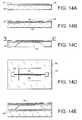
- Figures 14A, 14B, 14C and 14E are side views and in section.
- Figure 14D is a view of above corresponding to the plane DD of Figure 14C.
- Figure 14A shows a bracket 90 constituting the second substrate.
- An insulating layer 95 and a conductive layer 91 are successively deposited on one side of the second substrate 90.
- the figure 14D shows the shape given to the micro-catenary 93 and its connection pads 92.
- Another layer is deposited on the second substrate 90 covering the micro-catenary.
- Figure 14D is a view of above according to the plane DD indicated in FIG. 14C and without layer 96.
- the second substrate thus machined is solidarisé to a structure 98 of the type of that shown in Figure 11C.
- the solidarity is made so that the micro-catenary 93 is arranged opposite a row of activating electrodes (see Figure 14E). Electrical connections to the micro-catenary have not been shown.
- the micro-catenary is included between two layers playing the role of mechanical support.
- the layers 95 and 96 can be made in a prestressed material in tension in order to stretch and to stiffen the micro-catenary. This can be obtained from a second silicon substrate 90 on which layers 95 and 96 are deposited in nitride silicon by a PECVD process to control the stress level of the deposited material. This mode of realization also allows to coat the micro-catenary by an insulating material.
- micro-technologies allows so to structure the micro-catenaries by a stack of different layers. Can also draw different forms of micro-catenaries.
- FIG. 15 is a view from above of a device according to the invention showing a micro-catenary 103 provided with a first switch 108 and a second referral 109.
- the first referral 108 is connected to connection pads 110, 111 and the second referral 109 is connected to pads of connection 112, 113.
- the micro-catenary 103 and the switches 108 and 109 are arranged on a mechanical support. Turnouts allow mix, sort or split drops.
- Figure 16 is a top view of a Device according to the invention showing a micro-catenary 123 connected to connection pads 127.
- the micro-catenary 123 is disposed on a support 122 having a wave shape allowing promote the positioning of drops on the micro-catenary by the capillary forces.
Landscapes
- Engineering & Computer Science (AREA)
- Chemical & Material Sciences (AREA)
- Dispersion Chemistry (AREA)
- Health & Medical Sciences (AREA)
- General Engineering & Computer Science (AREA)
- Mechanical Engineering (AREA)
- General Health & Medical Sciences (AREA)
- Chemical Kinetics & Catalysis (AREA)
- Clinical Laboratory Science (AREA)
- Hematology (AREA)
- Analytical Chemistry (AREA)
- Physical Or Chemical Processes And Apparatus (AREA)
- Sampling And Sample Adjustment (AREA)
- Automatic Analysis And Handling Materials Therefor (AREA)
- External Artificial Organs (AREA)
- Chemical Or Physical Treatment Of Fibers (AREA)
Abstract
Description
- la figure 1 représente de manière simplifiée une première variante de réalisation d'un dispositif de déplacement de petits volumes de liquide selon la présente invention,
- la figure 2 représente de manière simplifiée une deuxième variante de réalisation d'un dispositif de déplacement de petits volumes de liquide selon la présente invention,
- la figure 3 représente de manière simplifiée le dispositif de la deuxième variante de réalisation, dans une utilisation particulière,
- les figures 4 et 5 illustrent un mode de fonctionnement du dispositif de la figure 3,
- la figure 6 représente de manière simplifiée une troisième variante de réalisation d'un dispositif de déplacement de petits volumes de liquide selon la présente invention,
- la figure 7 représente un dispositif de déplacement de petits volumes de liquide, à plusieurs micro-caténaires, selon la présente invention,
- la figure 8 représente un dispositif de déplacement de petits volumes de liquide comportant deux séries de micro-caténaires croisées, selon la présente invention,
- la figure 9 représente un dispositif de déplacement de petits volumes de liquide à micro-caténaire contrôlé en température,
- la figure 10 est une vue de dessus d'un dispositif de déplacement de petits volumes de liquide selon l'invention, en cours de fabrication,
- les figures 11A à 11F sont des vues correspondant à la coupe XX de la figure 10 et illustrent le procédé de fabrication du dispositif correspondant à la figure 10,
- les figures 12A et 12B sont des vues en coupe, respectivement longitudinale et transversale, d'un autre dispositif de déplacement de petits volumes de liquide selon l'invention,
- les figures 13A à 13D illustrent le procédé de fabrication d'un autre dispositif de déplacement de petits volumes de liquide selon l'invention,
- les figures 14A à 14E illustrent le procédé de fabrication d'encore un autre dispositif de déplacement de petits volumes de liquide selon l'invention,
- la figure 15 est une vue de dessus d'un dispositif de déplacement de petits volumes de liquide, mettant en oeuvre des aiguillages, selon l'invention,
- la figure 16 est une vue de dessus d'un dispositif de déplacement de petits volumes de liquide, présentant des emplacements préférentiels pour les petits volumes de liquide, selon l'invention.
- si l'électrode 12 est mouillante (voir la figure 5), la goutte 15 restera naturellement accrochée à la surface par les forces de capillarité, le processus est alors irréversible ;
- si la surface de l'électrode 12 est très hydrophobe, la goutte démouillera de la surface pour revenir à la position illustrée par la figure 3 et dans ce cas le processus est réversible, c'est-à-dire que l'on peut à volonté imposer le contact entre la goutte et l'électrode d'activation en jouant sur la tension d'activation.
- la goutte glisse en restant toujours en contact à la surface du substrat,
- la goutte se déplace sans qu'il y ait contact avec la surface du substrat. Dans ce dernier cas, on peut, par exemple après un déplacement sans contact sur une certaine longueur de caténaire, imposer temporairement l'étalement de la goutte sur la surface du substrat ou transférer la goutte du micro-caténaire vers la surface du substrat.
Claims (22)
- Dispositif de déplacement d'au moins un petit volume de liquide (5, 15) sous l'effet d'une commande électrique, comprenant un substrat (1, 11) pourvu de premiers moyens électriquement conducteurs (2, 12), le dispositif comprenant également des deuxièmes moyens électriquement conducteurs disposés en vis-à-vis des premiers moyens électriquement conducteurs, les premiers moyens électriquement conducteurs et les deuxièmes moyens électriquement conducteurs pouvant être reliés à des moyens d'alimentation électrique pour permettre l'application de forces électrostatiques au petit volume de liquide (5, 15), caractérisé en ce que les deuxièmes moyens électriquement conducteurs comprennent au moins un fil conducteur (3, 13) disposé parallèlement au substrat et à une distance déterminée du substrat pour permettre le déplacement du petit volume de liquide le long dudit fil conducteur sous l'effet des forces électrostatiques appliquées.
- Dispositif selon la revendication 1, caractérisé en ce que les premiers moyens électriquement conducteurs comprennent des électrodes (2, 12) disposées sur une face non électriquement conductrice du substrat et alignées suivant la direction du fil conducteur.
- Dispositif selon la revendication 1, caractérisé en ce que le fil conducteur (13) est mouillant pour le liquide du petit volume de liquide.
- Dispositif selon la revendication 1, caractérisé en ce que les premiers moyens électriquement conducteurs (62) et/ou les deuxièmes moyens électriquement conducteurs sont recouverts d'une couche de matériau électriquement isolant (68).
- Dispositif selon la revendication 1, caractérisé en ce qu'il comprend un milieu ambiant (4) dans lequel le petit volume de liquide (5) se déplace, ce milieu ambiant étant constitué par un gaz ou un liquide non miscible avec le petit volume de liquide.
- Dispositif selon la revendication 5, caractérisé en ce que le liquide non miscible avec le petit volume de liquide est un bain d'huile.
- Dispositif selon la revendication 1, caractérisé en ce que la distance déterminée entre le fil conducteur (3) et le substrat (1) est telle que le petit volume de liquide (5) est, en l'absence de forces électrostatiques appliquées, en contact avec le substrat, le substrat offrant un contact non mouillant avec le liquide du petit volume de liquide.
- Dispositif selon la revendication 1, caractérisé en ce que la distance déterminée entre le fil conducteur (13) et le substrat (11) et le diamètre du fil conducteur (13) sont tels que le petit volume de liquide (15) n'est pas, en l'absence de forces électrostatiques appliquées, en contact avec le substrat.
- Dispositif selon la revendication 8, caractérisé en ce que la distance déterminée entre le fil conducteur et le substrat et le diamètre du fil conducteur sont tels que le petit volume de liquide n'est pas, en présence de forces électrostatiques de déplacement appliquées, en contact avec le substrat.
- Dispositif selon la revendication 8, caractérisé en ce que le fil conducteur (13) étant disposé au-dessous du substrat (11), la distance déterminée entre le fil conducteur et le substrat est telle qu'une première valeur de forces électrostatiques appliquées provoque un contact entre le petit volume de liquide et le substrat.
- Dispositif selon la revendication 10, caractérisé en ce que le substrat offre un contact mouillant au petit volume de liquide (15) de manière à transférer le petit volume de liquide sur le substrat lorsque les forces électrostatiques appliquées sont annulées ou suffisamment diminuées.
- Dispositif selon la revendication 10, caractérisé en ce que le substrat offre un contact hydrophobe au petit volume de liquide de manière que le petit volume de liquide (15) soit supporté uniquement par le fil conducteur lorsque les forces électrostatiques appliquées sont annulées ou suffisamment diminuées.
- Dispositif selon la revendication 1, caractérisé en ce qu'il comporte des moyens (77) permettant d'auto-aligner et d'auto-positionner le fil conducteur (73) avec des moyens d'amenée et/ou d'évacuation du petit volume de liquide (72).
- Dispositif selon la revendication 13, caractérisé en ce que les moyens d'amenée et/ou d'évacuation du petit volume de liquide comprennent au moins un micro-capillaire (72).
- Dispositif selon la revendication 1, caractérisé en ce que le substrat (21) offre au petit volume de liquide une surface (22) de rugosité asymétrique, la distance entre le fil conducteur et le substrat étant telle que, sous l'effet de forces électrostatiques appliquées, le petit volume de liquide (25) est au contact du substrat qui, par sa surface de rugosité asymétrique, favorise le déplacement du petit volume de liquide.
- Dispositif selon la revendication 15, caractérisé en ce que la surface de rugosité asymétrique a un profil en toit d'usine.
- Dispositif selon l'une des revendications 15 ou 16, caractérisé en ce que la surface offerte par le substrat au petit volume de liquide est non mouillante.
- Dispositif selon l'une quelconque des revendications 1 à 17, caractérisé en ce que les premiers moyens électriquement conducteurs comprennent une matrice d'électrodes (32) formant des lignes et des colonnes, les deuxièmes moyens électriquement conducteurs comprenant des fils conducteurs (33), à chaque ligne d'électrodes correspondant un fil conducteur.
- Dispositif selon l'une quelconque des revendications 1 à 17, caractérisé en ce que les premiers moyens électriquement conducteurs comprennent une matrice d'électrodes (42) formant des lignes et des colonnes, les deuxièmes moyens électriquement conducteurs comprenant une première série de fils conducteurs (43) et une deuxième série de fils conducteurs (47), chaque ligne d'électrodes correspondant un fil conducteur de la première série de fils conducteurs, chaque colonne d'électrodes correspondant un fil conducteur de la deuxième série de fils conducteurs.
- Dispositif selon l'une quelconque des revendications précédentes, caractérisé en ce qu'il comprend des moyens pour chauffer le(s) fil(s) conducteur(s) (53).
- Dispositif selon la revendication 20, caractérisé en ce que les moyens de chauffage sont des moyens électriques permettant la circulation d'un courant électrique dans le (s) fil(s) conducteur(s) (53).
- Dispositif selon la revendication 21, caractérisé en ce qu'il comprend des moyens de contrôle de la température du (des) fil(s) conducteur (s) à partir de la mesure de la résistance électrique du (des) fil(s) conducteur(s) (53).
Applications Claiming Priority (2)
| Application Number | Priority Date | Filing Date | Title |
|---|---|---|---|
| FR0207477 | 2002-06-18 | ||
| FR0207477A FR2841063B1 (fr) | 2002-06-18 | 2002-06-18 | Dispositif de deplacement de petits volumes de liquide le long d'un micro-catenaire par des forces electrostatiques |
Publications (2)
| Publication Number | Publication Date |
|---|---|
| EP1376846A1 true EP1376846A1 (fr) | 2004-01-02 |
| EP1376846B1 EP1376846B1 (fr) | 2006-08-16 |
Family
ID=29595335
Family Applications (1)
| Application Number | Title | Priority Date | Filing Date |
|---|---|---|---|
| EP03101771A Expired - Lifetime EP1376846B1 (fr) | 2002-06-18 | 2003-06-17 | Dispositif de déplacement de petits volumes de liquide le long d'un micro-catenaire par des forces électrostatiques |
Country Status (8)
| Country | Link |
|---|---|
| US (1) | US7052244B2 (fr) |
| EP (1) | EP1376846B1 (fr) |
| JP (1) | JP4350979B2 (fr) |
| AT (1) | ATE336824T1 (fr) |
| AU (1) | AU2003204633B2 (fr) |
| CA (1) | CA2432607A1 (fr) |
| DE (1) | DE60307552T2 (fr) |
| FR (1) | FR2841063B1 (fr) |
Cited By (1)
| Publication number | Priority date | Publication date | Assignee | Title |
|---|---|---|---|---|
| FR2982176A1 (fr) * | 2011-11-09 | 2013-05-10 | Commissariat Energie Atomique | Dispositif et procede de manipulation des gouttes |
Families Citing this family (188)
| Publication number | Priority date | Publication date | Assignee | Title |
|---|---|---|---|---|
| US7329545B2 (en) * | 2002-09-24 | 2008-02-12 | Duke University | Methods for sampling a liquid flow |
| US6989234B2 (en) * | 2002-09-24 | 2006-01-24 | Duke University | Method and apparatus for non-contact electrostatic actuation of droplets |
| US6911132B2 (en) * | 2002-09-24 | 2005-06-28 | Duke University | Apparatus for manipulating droplets by electrowetting-based techniques |
| US7041481B2 (en) | 2003-03-14 | 2006-05-09 | The Regents Of The University Of California | Chemical amplification based on fluid partitioning |
| FR2866493B1 (fr) * | 2004-02-16 | 2010-08-20 | Commissariat Energie Atomique | Dispositif de controle du deplacement d'une goutte entre deux ou plusieurs substrats solides |
| US7048889B2 (en) * | 2004-03-23 | 2006-05-23 | Lucent Technologies Inc. | Dynamically controllable biological/chemical detectors having nanostructured surfaces |
| EP1743195A2 (fr) * | 2004-04-24 | 2007-01-17 | Koninklijke Philips Electronics N.V. | Dispositif optique a base de liquide, procede de commande de ce dispositif et dispositif electronique |
| FR2871070B1 (fr) * | 2004-06-02 | 2007-02-16 | Commissariat Energie Atomique | Microdispositif et procede de separation d'emulsion |
| FR2872574B1 (fr) * | 2004-07-01 | 2006-11-17 | Commissariat Energie Atomique | Systeme de detection synchrone de fluorescence en goutte |
| FR2872438B1 (fr) * | 2004-07-01 | 2006-09-15 | Commissariat Energie Atomique | Dispositif de deplacement et de traitement de volumes de liquide |
| FR2872575A1 (fr) * | 2004-07-01 | 2006-01-06 | Commissariat Energie Atomique | Procede et dispositif d'analyse de petits volumes de liquide |
| FR2872809B1 (fr) | 2004-07-09 | 2006-09-15 | Commissariat Energie Atomique | Methode d'adressage d'electrodes |
| EP1789195B1 (fr) | 2004-08-26 | 2010-10-27 | Life Technologies Corporation | Distributeurs à électromouillage et procédés associés |
| JP4185904B2 (ja) * | 2004-10-27 | 2008-11-26 | 株式会社日立ハイテクノロジーズ | 液体搬送基板、分析システム、分析方法 |
| FR2879946B1 (fr) | 2004-12-23 | 2007-02-09 | Commissariat Energie Atomique | Dispositif de dispense de gouttes |
| JP4427461B2 (ja) * | 2005-01-21 | 2010-03-10 | 株式会社日立ハイテクノロジーズ | 化学分析装置及び分析デバイス |
| CA2594483C (fr) | 2005-01-28 | 2014-08-26 | Duke University | Appareils et procedes de manipulation de gouttelettes sur une carte de circuits imprimes |
| US7454988B2 (en) * | 2005-02-10 | 2008-11-25 | Applera Corporation | Method for fluid sampling using electrically controlled droplets |
| CA2606750C (fr) | 2005-05-11 | 2015-11-24 | Nanolytics, Inc. | Procede ou dispositif pour conduire des reactions chimiques ou biochimiques a des temperatures multiples |
| US20060260919A1 (en) * | 2005-05-17 | 2006-11-23 | Marco Aimi | Methods and apparatus for filling a microswitch with liquid metal |
| JP4547304B2 (ja) * | 2005-05-31 | 2010-09-22 | 株式会社日立ハイテクノロジーズ | 液体搬送基板及び分析システム |
| FR2887030B1 (fr) * | 2005-06-09 | 2008-06-13 | Commissariat Energie Atomique | Dispositif planaire avec adressage de puits automatise par electromouillage dynamique |
| FR2887305B1 (fr) | 2005-06-17 | 2011-05-27 | Commissariat Energie Atomique | Dispositif de pompage par electromouillage et application aux mesures d'activite electrique |
| FR2888912B1 (fr) | 2005-07-25 | 2007-08-24 | Commissariat Energie Atomique | Procede de commande d'une communication entre deux zones par electromouillage, dispositif comportant des zones isolables les unes des autres et procede de realisation d'un tel dispositif |
| US20140193807A1 (en) | 2006-04-18 | 2014-07-10 | Advanced Liquid Logic, Inc. | Bead manipulation techniques |
| US8613889B2 (en) * | 2006-04-13 | 2013-12-24 | Advanced Liquid Logic, Inc. | Droplet-based washing |
| US8492168B2 (en) * | 2006-04-18 | 2013-07-23 | Advanced Liquid Logic Inc. | Droplet-based affinity assays |
| US8637317B2 (en) * | 2006-04-18 | 2014-01-28 | Advanced Liquid Logic, Inc. | Method of washing beads |
| US9476856B2 (en) | 2006-04-13 | 2016-10-25 | Advanced Liquid Logic, Inc. | Droplet-based affinity assays |
| US8637324B2 (en) | 2006-04-18 | 2014-01-28 | Advanced Liquid Logic, Inc. | Bead incubation and washing on a droplet actuator |
| US7815871B2 (en) * | 2006-04-18 | 2010-10-19 | Advanced Liquid Logic, Inc. | Droplet microactuator system |
| US8716015B2 (en) * | 2006-04-18 | 2014-05-06 | Advanced Liquid Logic, Inc. | Manipulation of cells on a droplet actuator |
| US7763471B2 (en) * | 2006-04-18 | 2010-07-27 | Advanced Liquid Logic, Inc. | Method of electrowetting droplet operations for protein crystallization |
| US8809068B2 (en) | 2006-04-18 | 2014-08-19 | Advanced Liquid Logic, Inc. | Manipulation of beads in droplets and methods for manipulating droplets |
| US7816121B2 (en) * | 2006-04-18 | 2010-10-19 | Advanced Liquid Logic, Inc. | Droplet actuation system and method |
| US8658111B2 (en) | 2006-04-18 | 2014-02-25 | Advanced Liquid Logic, Inc. | Droplet actuators, modified fluids and methods |
| US8470606B2 (en) * | 2006-04-18 | 2013-06-25 | Duke University | Manipulation of beads in droplets and methods for splitting droplets |
| US8980198B2 (en) * | 2006-04-18 | 2015-03-17 | Advanced Liquid Logic, Inc. | Filler fluids for droplet operations |
| US10078078B2 (en) | 2006-04-18 | 2018-09-18 | Advanced Liquid Logic, Inc. | Bead incubation and washing on a droplet actuator |
| WO2007123908A2 (fr) * | 2006-04-18 | 2007-11-01 | Advanced Liquid Logic, Inc. | Opérations en puits multiples à base de gouttelettes |
| US7727723B2 (en) | 2006-04-18 | 2010-06-01 | Advanced Liquid Logic, Inc. | Droplet-based pyrosequencing |
| US7901947B2 (en) | 2006-04-18 | 2011-03-08 | Advanced Liquid Logic, Inc. | Droplet-based particle sorting |
| US7439014B2 (en) * | 2006-04-18 | 2008-10-21 | Advanced Liquid Logic, Inc. | Droplet-based surface modification and washing |
| US8041463B2 (en) * | 2006-05-09 | 2011-10-18 | Advanced Liquid Logic, Inc. | Modular droplet actuator drive |
| WO2009111769A2 (fr) | 2008-03-07 | 2009-09-11 | Advanced Liquid Logic, Inc. | Réactif et préparation et chargement d’un échantillon sur un dispositif fluidique |
| US7939021B2 (en) * | 2007-05-09 | 2011-05-10 | Advanced Liquid Logic, Inc. | Droplet actuator analyzer with cartridge |
| US7822510B2 (en) * | 2006-05-09 | 2010-10-26 | Advanced Liquid Logic, Inc. | Systems, methods, and products for graphically illustrating and controlling a droplet actuator |
| FR2906237B1 (fr) | 2006-09-22 | 2008-12-19 | Commissariat Energie Atomique | Composants fluidiques double-face |
| US8685344B2 (en) * | 2007-01-22 | 2014-04-01 | Advanced Liquid Logic, Inc. | Surface assisted fluid loading and droplet dispensing |
| EP2570811B1 (fr) | 2007-02-09 | 2014-11-26 | Advanced Liquid Logic, Inc. | Dispositifs actionneurs de gouttelettes et procédés employant des perles magnétiques |
| US8872527B2 (en) * | 2007-02-15 | 2014-10-28 | Advanced Liquid Logic, Inc. | Capacitance detection in a droplet actuator |
| EP2837692A1 (fr) | 2007-03-22 | 2015-02-18 | Advanced Liquid Logic, Inc. | Dosages enzymatiques pour un actionneur de gouttelettes |
| WO2011084703A2 (fr) | 2009-12-21 | 2011-07-14 | Advanced Liquid Logic, Inc. | Analyses d'enzymes sur un diffuseur à gouttelettes |
| US8202686B2 (en) * | 2007-03-22 | 2012-06-19 | Advanced Liquid Logic, Inc. | Enzyme assays for a droplet actuator |
| CN101743304B (zh) * | 2007-04-10 | 2013-04-24 | 先进流体逻辑公司 | 微滴分配设备和方法 |
| WO2008147568A1 (fr) * | 2007-05-24 | 2008-12-04 | Digital Biosystems | Microfluidique numérique basée sur l'électromouillage |
| WO2009002920A1 (fr) | 2007-06-22 | 2008-12-31 | Advanced Liquid Logic, Inc. | Amplification d'acide nucléique à base de gouttelette dans un gradient de température |
| US20100120130A1 (en) * | 2007-08-08 | 2010-05-13 | Advanced Liquid Logic, Inc. | Droplet Actuator with Droplet Retention Structures |
| WO2009021233A2 (fr) | 2007-08-09 | 2009-02-12 | Advanced Liquid Logic, Inc. | Fabrication d'un dispositif de manipulation de gouttelettes sur pcb |
| WO2009029561A2 (fr) * | 2007-08-24 | 2009-03-05 | Advanced Liquid Logic, Inc. | Manipulations de perles sur un actionneur à gouttelettes |
| WO2009032863A2 (fr) * | 2007-09-04 | 2009-03-12 | Advanced Liquid Logic, Inc. | Actionneur de gouttelette avec substrat supérieur amélioré |
| DE102007047415B3 (de) * | 2007-10-04 | 2009-04-02 | Dräger Medical AG & Co. KG | Flüssigkeitsverdampfer |
| US8460528B2 (en) * | 2007-10-17 | 2013-06-11 | Advanced Liquid Logic Inc. | Reagent storage and reconstitution for a droplet actuator |
| US20100236928A1 (en) * | 2007-10-17 | 2010-09-23 | Advanced Liquid Logic, Inc. | Multiplexed Detection Schemes for a Droplet Actuator |
| WO2009052321A2 (fr) * | 2007-10-18 | 2009-04-23 | Advanced Liquid Logic, Inc. | Actionneurs de gouttelettes, systèmes et procédés |
| EP2232535A4 (fr) * | 2007-12-10 | 2016-04-13 | Advanced Liquid Logic Inc | Configurations d'actionneur de gouttelette et procédés |
| FR2925792B1 (fr) * | 2007-12-21 | 2012-12-07 | Commissariat Energie Atomique | Dispositif de recuperation d'energie a electrode liquide |
| AU2008345138B2 (en) | 2007-12-23 | 2014-05-29 | Advanced Liquid Logic, Inc. | Droplet actuator configurations and methods of conducting droplet operations |
| FR2930457B1 (fr) | 2008-04-24 | 2010-06-25 | Commissariat Energie Atomique | Procede de fabrication de microcanaux reconfigurables |
| US8852952B2 (en) | 2008-05-03 | 2014-10-07 | Advanced Liquid Logic, Inc. | Method of loading a droplet actuator |
| US20110097763A1 (en) * | 2008-05-13 | 2011-04-28 | Advanced Liquid Logic, Inc. | Thermal Cycling Method |
| EP2286228B1 (fr) * | 2008-05-16 | 2019-04-03 | Advanced Liquid Logic, Inc. | Dispositifs et procédés actionneurs de gouttelettes pour manipuler des billes |
| US11786036B2 (en) | 2008-06-27 | 2023-10-17 | Ssw Advanced Technologies, Llc | Spill containing refrigerator shelf assembly |
| US8286561B2 (en) | 2008-06-27 | 2012-10-16 | Ssw Holding Company, Inc. | Spill containing refrigerator shelf assembly |
| FR2934361B1 (fr) * | 2008-07-22 | 2012-12-28 | Commissariat Energie Atomique | Dispositif de variation de pression d'un fluide pneumatique par deplacement de gouttes de liquide et pompe a chaleur utilisant un tel dispositif |
| US8951939B2 (en) | 2011-07-12 | 2015-02-10 | Bio-Rad Laboratories, Inc. | Digital assays with multiplexed detection of two or more targets in the same optical channel |
| US9598725B2 (en) * | 2010-03-02 | 2017-03-21 | Bio-Rad Laboratories, Inc. | Emulsion chemistry for encapsulated droplets |
| US11130128B2 (en) | 2008-09-23 | 2021-09-28 | Bio-Rad Laboratories, Inc. | Detection method for a target nucleic acid |
| US8633015B2 (en) * | 2008-09-23 | 2014-01-21 | Bio-Rad Laboratories, Inc. | Flow-based thermocycling system with thermoelectric cooler |
| US9132394B2 (en) | 2008-09-23 | 2015-09-15 | Bio-Rad Laboratories, Inc. | System for detection of spaced droplets |
| WO2011120020A1 (fr) | 2010-03-25 | 2011-09-29 | Quantalife, Inc. | Système de transport de gouttelettes à des fins de détection |
| GB2502409B8 (en) | 2008-09-23 | 2014-10-15 | Bio Rad Laboratories | Droplet-based assay system |
| US8663920B2 (en) | 2011-07-29 | 2014-03-04 | Bio-Rad Laboratories, Inc. | Library characterization by digital assay |
| US10512910B2 (en) | 2008-09-23 | 2019-12-24 | Bio-Rad Laboratories, Inc. | Droplet-based analysis method |
| US9492797B2 (en) | 2008-09-23 | 2016-11-15 | Bio-Rad Laboratories, Inc. | System for detection of spaced droplets |
| US9399215B2 (en) | 2012-04-13 | 2016-07-26 | Bio-Rad Laboratories, Inc. | Sample holder with a well having a wicking promoter |
| US8709762B2 (en) | 2010-03-02 | 2014-04-29 | Bio-Rad Laboratories, Inc. | System for hot-start amplification via a multiple emulsion |
| US9764322B2 (en) | 2008-09-23 | 2017-09-19 | Bio-Rad Laboratories, Inc. | System for generating droplets with pressure monitoring |
| US9089844B2 (en) | 2010-11-01 | 2015-07-28 | Bio-Rad Laboratories, Inc. | System for forming emulsions |
| US9156010B2 (en) | 2008-09-23 | 2015-10-13 | Bio-Rad Laboratories, Inc. | Droplet-based assay system |
| US12162008B2 (en) | 2008-09-23 | 2024-12-10 | Bio-Rad Laboratories, Inc. | Partition-based method of analysis |
| US9417190B2 (en) | 2008-09-23 | 2016-08-16 | Bio-Rad Laboratories, Inc. | Calibrations and controls for droplet-based assays |
| US12090480B2 (en) | 2008-09-23 | 2024-09-17 | Bio-Rad Laboratories, Inc. | Partition-based method of analysis |
| FR2936351B1 (fr) | 2008-09-25 | 2010-10-15 | Commissariat Energie Atomique | Systeme a capacite variable a dielectrique souple. |
| FR2936654B1 (fr) * | 2008-09-26 | 2010-10-22 | Commissariat Energie Atomique | Antenne radiofrequence d'emission-reception a parametres d'emission-reception modifiables |
| WO2010042668A1 (fr) | 2008-10-07 | 2010-04-15 | Ross Technology Corporation | Surfaces anti-éclaboussures à bordures hydrophobes et oléophobes |
| US8877512B2 (en) * | 2009-01-23 | 2014-11-04 | Advanced Liquid Logic, Inc. | Bubble formation techniques using physical or chemical features to retain a gas bubble within a droplet actuator |
| US8926065B2 (en) | 2009-08-14 | 2015-01-06 | Advanced Liquid Logic, Inc. | Droplet actuator devices and methods |
| CA2767056C (fr) | 2009-09-02 | 2018-12-04 | Bio-Rad Laboratories, Inc. | Systeme de melange de fluides par coalescence d'emulsions multiples |
| US8846414B2 (en) | 2009-09-29 | 2014-09-30 | Advanced Liquid Logic, Inc. | Detection of cardiac markers on a droplet actuator |
| EP2496886B1 (fr) | 2009-11-04 | 2016-12-21 | SSW Holding Company, Inc. | Surfaces d'appareils de cuisson ayant une configuration permettant la retenue des débordements et procédés de fabrication de ces surfaces |
| US9091649B2 (en) | 2009-11-06 | 2015-07-28 | Advanced Liquid Logic, Inc. | Integrated droplet actuator for gel; electrophoresis and molecular analysis |
| JP5882234B2 (ja) | 2010-02-25 | 2016-03-09 | アドバンスト リキッド ロジック インコーポレイテッドAdvanced Liquid Logic, Inc. | 核酸ライブラリーの作製方法 |
| CA2796305A1 (fr) | 2010-03-15 | 2011-09-22 | Ross Technology Corporation | Piston et procedes de production de surfaces hydrophobes |
| JP2013524171A (ja) | 2010-03-25 | 2013-06-17 | クァンタライフ・インコーポレーテッド | 液滴ベースのアッセイのための液滴の発生 |
| JP2013524169A (ja) | 2010-03-25 | 2013-06-17 | クァンタライフ・インコーポレーテッド | 液滴によるアッセイ用の検出システム |
| US9248450B2 (en) | 2010-03-30 | 2016-02-02 | Advanced Liquid Logic, Inc. | Droplet operations platform |
| US20190300945A1 (en) | 2010-04-05 | 2019-10-03 | Prognosys Biosciences, Inc. | Spatially Encoded Biological Assays |
| KR101866401B1 (ko) | 2010-04-05 | 2018-06-11 | 프로그노시스 바이오사이언스, 인코포레이티드 | 공간적으로 엔코딩된 생물학적 검정 |
| US10787701B2 (en) | 2010-04-05 | 2020-09-29 | Prognosys Biosciences, Inc. | Spatially encoded biological assays |
| EP2588322B1 (fr) | 2010-06-30 | 2015-06-17 | Advanced Liquid Logic, Inc. | Ensembles actionneurs à gouttelettes et leurs procédés de fabrication |
| EP2641097A4 (fr) | 2010-11-17 | 2016-09-07 | Détection de capacité dans un organe de commande de gouttelettes | |
| US12097495B2 (en) | 2011-02-18 | 2024-09-24 | Bio-Rad Laboratories, Inc. | Methods and compositions for detecting genetic material |
| WO2012115986A1 (fr) | 2011-02-21 | 2012-08-30 | Ross Technology Corporation | Revêtements très hydrophobes et oléophobes comprenant des systèmes de liants à faible teneur en cov |
| CA2830443C (fr) | 2011-03-18 | 2021-11-16 | Bio-Rad Laboratories, Inc. | Essais numeriques multiplexes avec utilisation combinee de signaux |
| GB201106254D0 (en) | 2011-04-13 | 2011-05-25 | Frisen Jonas | Method and product |
| US8339711B2 (en) * | 2011-04-22 | 2012-12-25 | Sharp Kabushiki Kaisha | Active matrix device and method of driving the same |
| JP2014512826A (ja) | 2011-04-25 | 2014-05-29 | バイオ−ラド ラボラトリーズ インコーポレイテッド | 核酸分析のための方法および組成物 |
| US20140174926A1 (en) | 2011-05-02 | 2014-06-26 | Advanced Liquid Logic, Inc. | Molecular diagnostics platform |
| EP2707131B1 (fr) | 2011-05-09 | 2019-04-24 | Advanced Liquid Logic, Inc. | Rétroaction microfluidique utilisant une détection d'impédance |
| US9140635B2 (en) | 2011-05-10 | 2015-09-22 | Advanced Liquid Logic, Inc. | Assay for measuring enzymatic modification of a substrate by a glycoprotein having enzymatic activity |
| US8901043B2 (en) | 2011-07-06 | 2014-12-02 | Advanced Liquid Logic, Inc. | Systems for and methods of hybrid pyrosequencing |
| JP5894272B2 (ja) | 2011-07-06 | 2016-03-23 | アドバンスト リキッド ロジック インコーポレイテッドAdvanced Liquid Logic, Inc. | 液滴アクチュエーターにおける試薬保存 |
| WO2013009927A2 (fr) | 2011-07-11 | 2013-01-17 | Advanced Liquid Logic, Inc. | Actionneurs de gouttelettes et techniques pour dosages à base de gouttelettes |
| WO2013016413A2 (fr) | 2011-07-25 | 2013-01-31 | Advanced Liquid Logic Inc | Dispositif et système d'actionneur à gouttelettes |
| DE102011085428A1 (de) | 2011-10-28 | 2013-05-02 | Schott Ag | Einlegeboden |
| WO2013078216A1 (fr) | 2011-11-21 | 2013-05-30 | Advanced Liquid Logic Inc | Dosages de la glucose-6-phosphate déshydrogénase |
| WO2013090939A1 (fr) | 2011-12-15 | 2013-06-20 | Ross Technology Corporation | Composition et revêtement pour une performance superhydrophobe |
| US9223317B2 (en) | 2012-06-14 | 2015-12-29 | Advanced Liquid Logic, Inc. | Droplet actuators that include molecular barrier coatings |
| BR112014032676A2 (pt) | 2012-06-25 | 2017-06-27 | Ross Tech Corporation | revestimentos elastoméricos que têm propriedades hidrofóbicas e/ou oleofóbicas |
| EP2867645B1 (fr) | 2012-06-27 | 2019-06-05 | Advanced Liquid Logic, Inc. | Techniques et conceptions de dispositif de commande de gouttelette permettant de réduire la formation de bulles |
| WO2014062551A1 (fr) | 2012-10-15 | 2014-04-24 | Advanced Liquid Logic, Inc. | Cartouche microfluidique numérique et système pour la mise en œuvre d'une cuve à circulation |
| EP3901280B1 (fr) | 2012-10-17 | 2025-03-12 | 10x Genomics Sweden AB | Procédés et produits pour optimiser la detection localisée ou spatiale de l'expression génique dans un échantillon de tissu |
| CN111500680B (zh) | 2013-06-25 | 2024-04-16 | 普罗格诺西斯生物科学公司 | 检测样品中生物靶标的空间分布的方法和系统 |
| EP3033599A4 (fr) | 2013-08-13 | 2017-03-22 | Advanced Liquid Logic, Inc. | Procédés d'amélioration de la précision et de l'exactitude du comptage de gouttelettes faisant appel à un réservoir sur actionneur comme entrée de fluide |
| EP3038834B1 (fr) | 2013-08-30 | 2018-12-12 | Illumina, Inc. | Manipulation de gouttelettes sur des surfaces hydrophiles ou hydrophiles panachées |
| US20170044525A1 (en) | 2014-04-29 | 2017-02-16 | Illumina, Inc. | Multiplexed single cell gene expression analysis using template switch and tagmentation |
| US20150370707A1 (en) * | 2014-06-24 | 2015-12-24 | Qualcomm Incorporated | Disunited shared-information and private-information caches |
| MX391361B (es) | 2014-10-09 | 2025-03-21 | Illumina Inc | Metodo y dispositivo para la separacion de liquidos inmiscibles para aislar de modo efectivo al menos uno de los liquidos. |
| ES3062422T3 (en) | 2015-02-10 | 2026-04-10 | Illumina Inc | Compositions for analyzing cellular components |
| US10576471B2 (en) | 2015-03-20 | 2020-03-03 | Illumina, Inc. | Fluidics cartridge for use in the vertical or substantially vertical position |
| EP4321627A3 (fr) | 2015-04-10 | 2024-04-17 | 10x Genomics Sweden AB | Analyse de plusieurs acides nucléiques spatialement différenciés de spécimens biologiques |
| CN107810415B (zh) | 2015-05-11 | 2021-06-22 | 亿明达股份有限公司 | 用于发现和分析治疗剂的平台 |
| US10857537B2 (en) | 2015-07-06 | 2020-12-08 | Illumina, Inc. | Balanced AC modulation for driving droplet operations electrodes |
| CN108138229B (zh) | 2015-08-14 | 2022-07-26 | 亿明达股份有限公司 | 使用磁响应式传感器确定遗传特征的系统和方法 |
| CN108350497B (zh) | 2015-08-28 | 2022-07-19 | Illumina公司 | 单细胞核酸序列分析 |
| WO2017037078A1 (fr) | 2015-09-02 | 2017-03-09 | Illumina Cambridge Limited | Systèmes et procédés d'amélioration du comportement des gouttelettes dans des systèmes fluidiques |
| US10450598B2 (en) | 2015-09-11 | 2019-10-22 | Illumina, Inc. | Systems and methods for obtaining a droplet having a designated concentration of a substance-of-interest |
| EP3365108B1 (fr) | 2015-10-22 | 2024-06-12 | Illumina, Inc. | Fluide de remplissage pour dispositifs fluidiques |
| WO2017095845A1 (fr) | 2015-12-01 | 2017-06-08 | Illumina, Inc. | Mécanismes et procédés de stockage et de distribution de liquides |
| EP3907295A1 (fr) * | 2015-12-01 | 2021-11-10 | Illumina, Inc. | Procédé de compartimentation de reactions individuelles dans une ligne ou matrix de microcavités |
| EP3440220B1 (fr) | 2016-04-07 | 2020-03-25 | Illumina, Inc. | Procédés et systèmes de construction de banques d'acides nucléiques normalisées |
| JP6919181B2 (ja) * | 2016-11-29 | 2021-08-18 | 株式会社リコー | 液滴分注装置、液滴分注方法、及び被着対象物の製造方法 |
| KR101905139B1 (ko) * | 2017-02-17 | 2018-10-05 | 한국과학기술원 | 전기습윤 현상을 이용한 액체 거동 제어 장치 및 방법 |
| KR101926723B1 (ko) * | 2017-07-03 | 2018-12-07 | 한국과학기술원 | 전기습윤현상을 이용한 동적 액체 흐름 제어 장치 및 방법 |
| CA3089756A1 (fr) | 2018-01-29 | 2019-08-01 | St. Jude Children's Research Hospital, Inc. | Procede d'amplification d'acide nucleique |
| US20230220377A1 (en) | 2019-07-31 | 2023-07-13 | BioSkryb Genomics, Inc. | Single cell analysis |
| US12157124B2 (en) | 2019-11-06 | 2024-12-03 | 10X Genomics, Inc. | Imaging system hardware |
| US11927740B2 (en) | 2019-11-20 | 2024-03-12 | Nuclera Ltd | Spatially variable hydrophobic layers for digital microfluidics |
| US12405264B2 (en) | 2020-01-17 | 2025-09-02 | 10X Genomics, Inc. | Electrophoretic system and method for analyte capture |
| WO2021146573A1 (fr) | 2020-01-17 | 2021-07-22 | E Ink Corporation | Couches diélectriques variables spatialement pour la microfluidique numérique |
| WO2021154627A1 (fr) | 2020-01-27 | 2021-08-05 | E Ink Corporation | Procédé de dégazage de gouttelettes de liquide par électromouillage à des températures plus élevées |
| US12110541B2 (en) | 2020-02-03 | 2024-10-08 | 10X Genomics, Inc. | Methods for preparing high-resolution spatial arrays |
| CN115175764A (zh) | 2020-02-18 | 2022-10-11 | 核酸有限公司 | 用于EWoD阵列的高频AC驱动的自适应栅极驱动 |
| EP4106920A4 (fr) | 2020-02-19 | 2024-03-20 | Nuclera Ltd | Pilotage de transistor verrouillé pour l'attaque de ac à haute fréquence de réseaux ewod |
| US11596946B2 (en) | 2020-04-27 | 2023-03-07 | Nuclera Nucleics Ltd. | Segmented top plate for variable driving and short protection for digital microfluidics |
| US12416603B2 (en) | 2020-05-19 | 2025-09-16 | 10X Genomics, Inc. | Electrophoresis cassettes and instrumentation |
| EP4153775B1 (fr) | 2020-05-22 | 2024-07-24 | 10X Genomics, Inc. | Mesure spatio-temporelle simultanée de l'expression génique et de l'activité cellulaire |
| US12031177B1 (en) | 2020-06-04 | 2024-07-09 | 10X Genomics, Inc. | Methods of enhancing spatial resolution of transcripts |
| EP4164796A4 (fr) | 2020-06-10 | 2024-03-06 | 10x Genomics, Inc. | Procédés de distribution de fluide |
| US20230304066A1 (en) | 2020-09-04 | 2023-09-28 | Baebies, Inc. | Microfluidic based assay for unbound bilirubin |
| JP7716730B2 (ja) | 2020-09-15 | 2025-08-01 | 国立大学法人 名古屋工業大学 | 液体制御デバイス及びその利用 |
| CN116194590A (zh) | 2020-09-18 | 2023-05-30 | 10X基因组学有限公司 | 样品处理设备和图像配准方法 |
| US12179203B2 (en) | 2020-10-08 | 2024-12-31 | Nuclera Ltd | Method for reagent-specific driving EWoD arrays in microfluidic systems |
| US12128411B2 (en) | 2020-11-04 | 2024-10-29 | Nuclera Ltd | Dielectric layers for digital microfluidic devices |
| ES2989523T3 (es) | 2021-02-19 | 2024-11-26 | 10X Genomics Inc | Método de uso de un dispositivo modular de soporte para ensayos |
| JP7528850B2 (ja) * | 2021-04-12 | 2024-08-06 | トヨタ自動車株式会社 | アクチュエータ |
| US12458185B2 (en) * | 2021-05-05 | 2025-11-04 | Kohler Co. | Hydrophobic field |
| WO2022256514A1 (fr) | 2021-06-02 | 2022-12-08 | Baebies, Inc. | Régulation thermique micro-régionale pour la microfluidique numérique |
| US12553805B2 (en) | 2021-08-02 | 2026-02-17 | 10X Genomics, Inc. | Methods of preserving a biological sample |
| USD1064308S1 (en) | 2021-09-17 | 2025-02-25 | 10X Genomics, Inc. | Sample handling device |
| FR3127810A1 (fr) | 2021-10-01 | 2023-04-07 | Commissariat à l'Energie Atomique et aux Energies Alternatives | Procédé de tri de gouttes |
| EP4441711A1 (fr) | 2021-12-20 | 2024-10-09 | 10X Genomics, Inc. | Auto-test pour dispositif d'imagerie |
| US12637706B2 (en) | 2022-03-23 | 2026-05-26 | 10X Genomics, Inc. | Methods and compositions related to microsphere surface gelation |
| EP4594519A1 (fr) | 2022-09-27 | 2025-08-06 | Nautilus Subsidiary, Inc. | Capture de polypeptides, fragmentation et identification in situ |
| US20250060333A1 (en) | 2023-08-16 | 2025-02-20 | E Ink Corporation | Devices, methods, and systems for visualizing electrowetting pathing using electrophoretic materials |
| FR3153756B1 (fr) | 2023-10-06 | 2026-06-26 | Commissariat Energie Atomique | Système d'analyse optique d'un échantillon |
| CN119771522B (zh) * | 2024-12-13 | 2025-10-28 | 广州大学 | 一种液滴运输磁控薄膜机器人及其制备方法和应用 |
Citations (3)
| Publication number | Priority date | Publication date | Assignee | Title |
|---|---|---|---|---|
| US4569575A (en) * | 1983-06-30 | 1986-02-11 | Thomson-Csf | Electrodes for a device operating by electrically controlled fluid displacement |
| US5181016A (en) * | 1991-01-15 | 1993-01-19 | The United States Of America As Represented By The United States Department Of Energy | Micro-valve pump light valve display |
| FR2794039A1 (fr) * | 1999-05-27 | 2000-12-01 | Osmooze Sa | Dispositif de formation, de deplacement et de diffusion de petites quantites calibrees de liquides |
-
2002
- 2002-06-18 FR FR0207477A patent/FR2841063B1/fr not_active Expired - Fee Related
-
2003
- 2003-06-10 US US10/457,375 patent/US7052244B2/en not_active Expired - Lifetime
- 2003-06-11 AU AU2003204633A patent/AU2003204633B2/en not_active Ceased
- 2003-06-17 AT AT03101771T patent/ATE336824T1/de not_active IP Right Cessation
- 2003-06-17 CA CA002432607A patent/CA2432607A1/fr not_active Abandoned
- 2003-06-17 EP EP03101771A patent/EP1376846B1/fr not_active Expired - Lifetime
- 2003-06-17 DE DE60307552T patent/DE60307552T2/de not_active Expired - Lifetime
- 2003-06-18 JP JP2003173970A patent/JP4350979B2/ja not_active Expired - Fee Related
Patent Citations (3)
| Publication number | Priority date | Publication date | Assignee | Title |
|---|---|---|---|---|
| US4569575A (en) * | 1983-06-30 | 1986-02-11 | Thomson-Csf | Electrodes for a device operating by electrically controlled fluid displacement |
| US5181016A (en) * | 1991-01-15 | 1993-01-19 | The United States Of America As Represented By The United States Department Of Energy | Micro-valve pump light valve display |
| FR2794039A1 (fr) * | 1999-05-27 | 2000-12-01 | Osmooze Sa | Dispositif de formation, de deplacement et de diffusion de petites quantites calibrees de liquides |
Cited By (2)
| Publication number | Priority date | Publication date | Assignee | Title |
|---|---|---|---|---|
| FR2982176A1 (fr) * | 2011-11-09 | 2013-05-10 | Commissariat Energie Atomique | Dispositif et procede de manipulation des gouttes |
| EP2591857A1 (fr) * | 2011-11-09 | 2013-05-15 | Commissariat à l'Énergie Atomique et aux Énergies Alternatives | Dispositif et procédé de manipulation des gouttes |
Also Published As
| Publication number | Publication date |
|---|---|
| FR2841063A1 (fr) | 2003-12-19 |
| CA2432607A1 (fr) | 2003-12-18 |
| EP1376846B1 (fr) | 2006-08-16 |
| US7052244B2 (en) | 2006-05-30 |
| JP4350979B2 (ja) | 2009-10-28 |
| JP2004022165A (ja) | 2004-01-22 |
| ATE336824T1 (de) | 2006-09-15 |
| DE60307552T2 (de) | 2007-08-09 |
| AU2003204633B2 (en) | 2008-07-17 |
| AU2003204633A1 (en) | 2004-01-15 |
| US20040007377A1 (en) | 2004-01-15 |
| FR2841063B1 (fr) | 2004-09-17 |
| DE60307552D1 (de) | 2006-09-28 |
Similar Documents
| Publication | Publication Date | Title |
|---|---|---|
| EP1376846B1 (fr) | Dispositif de déplacement de petits volumes de liquide le long d'un micro-catenaire par des forces électrostatiques | |
| EP1386657A1 (fr) | Dispositif d'injection et de mélange de micro-gouttes liquides | |
| FR2866493A1 (fr) | Dispositif de controle du deplacement d'une goutte entre deux ou plusieurs substrats solides | |
| US6949176B2 (en) | Microfluidic control using dielectric pumping | |
| US8883014B2 (en) | Monolithically formed EWOD device and method of making the same | |
| US8342207B2 (en) | Making a liquid/liquid or gas system in microfluidics | |
| Zhao et al. | Micro air bubble manipulation by electrowetting on dielectric (EWOD): transporting, splitting, merging and eliminating of bubbles | |
| Chiou et al. | Droplet manipulation with light on optoelectrowetting device | |
| Lee et al. | Electrowetting-induced droplet detachment from hydrophobic surfaces | |
| EP2545371B1 (fr) | Dispositif à canaux microfluidiques comportant une rangée d'électrodes d'attaque | |
| WO2006134307A1 (fr) | Dispositif de pompage par electromouillage et application aux mesures d'activite electrique | |
| FR2884437A1 (fr) | Dispositif et procede microfluidique de transfert de matiere entre deux phases immiscibles. | |
| US8679423B2 (en) | Method for producing reconfigurable microchannels | |
| FR2820058A1 (fr) | Procede et systeme permettant de realiser en flux continu un protocole biologique, chimique ou biochimique | |
| Yasui et al. | Inkjet injection of DNA droplets for microchannel array electrophoresis | |
| US20120111506A1 (en) | Method for the controlled evaporation of a liquid drop in a microfluidic device | |
| EP2591857A1 (fr) | Dispositif et procédé de manipulation des gouttes | |
| FR2831081A1 (fr) | Dispositif d'injection parallelisee et synchronisee pour injections sequentielles de reactifs differents | |
| FR2937690A1 (fr) | Micropome a actionnement par gouttes | |
| Bian et al. | A novel crescent electrode for droplet splitting in digital microfluidic | |
| Berry et al. | New Methods to Transport Fluids in Micro-Sized Devices | |
| Zeng et al. | Droplet creator based on electrowetting-on-dielectric for lab on a chip | |
| Yeo et al. | Electrowetting, Applications | |
| Royal et al. | Integrated sample preparation and sensing: Microresonator optical sensors embedded in digital electrowetting microfluidics systems | |
| Pei et al. | On-chip blade for accurate splitting of droplets in light-actuated digital microfluidics |
Legal Events
| Date | Code | Title | Description |
|---|---|---|---|
| PUAI | Public reference made under article 153(3) epc to a published international application that has entered the european phase |
Free format text: ORIGINAL CODE: 0009012 |
|
| AK | Designated contracting states |
Kind code of ref document: A1 Designated state(s): AT BE BG CH CY CZ DE DK EE ES FI FR GB GR HU IE IT LI LU MC NL PT RO SE SI SK TR |
|
| AX | Request for extension of the european patent |
Extension state: AL LT LV MK |
|
| 17P | Request for examination filed |
Effective date: 20040630 |
|
| AKX | Designation fees paid |
Designated state(s): AT BE BG CH CY CZ DE DK EE ES FI FR GB GR HU IE IT LI LU MC NL PT RO SE SI SK TR |
|
| 17Q | First examination report despatched |
Effective date: 20041202 |
|
| GRAP | Despatch of communication of intention to grant a patent |
Free format text: ORIGINAL CODE: EPIDOSNIGR1 |
|
| GRAS | Grant fee paid |
Free format text: ORIGINAL CODE: EPIDOSNIGR3 |
|
| GRAA | (expected) grant |
Free format text: ORIGINAL CODE: 0009210 |
|
| AK | Designated contracting states |
Kind code of ref document: B1 Designated state(s): AT BE BG CH CY CZ DE DK EE ES FI FR GB GR HU IE IT LI LU MC NL PT RO SE SI SK TR |
|
| PG25 | Lapsed in a contracting state [announced via postgrant information from national office to epo] |
Ref country code: IT Free format text: LAPSE BECAUSE OF FAILURE TO SUBMIT A TRANSLATION OF THE DESCRIPTION OR TO PAY THE FEE WITHIN THE PRESCRIBED TIME-LIMIT;WARNING: LAPSES OF ITALIAN PATENTS WITH EFFECTIVE DATE BEFORE 2007 MAY HAVE OCCURRED AT ANY TIME BEFORE 2007. THE CORRECT EFFECTIVE DATE MAY BE DIFFERENT FROM THE ONE RECORDED. Effective date: 20060816 Ref country code: RO Free format text: LAPSE BECAUSE OF FAILURE TO SUBMIT A TRANSLATION OF THE DESCRIPTION OR TO PAY THE FEE WITHIN THE PRESCRIBED TIME-LIMIT Effective date: 20060816 Ref country code: FI Free format text: LAPSE BECAUSE OF FAILURE TO SUBMIT A TRANSLATION OF THE DESCRIPTION OR TO PAY THE FEE WITHIN THE PRESCRIBED TIME-LIMIT Effective date: 20060816 Ref country code: SK Free format text: LAPSE BECAUSE OF FAILURE TO SUBMIT A TRANSLATION OF THE DESCRIPTION OR TO PAY THE FEE WITHIN THE PRESCRIBED TIME-LIMIT Effective date: 20060816 Ref country code: SI Free format text: LAPSE BECAUSE OF FAILURE TO SUBMIT A TRANSLATION OF THE DESCRIPTION OR TO PAY THE FEE WITHIN THE PRESCRIBED TIME-LIMIT Effective date: 20060816 Ref country code: CZ Free format text: LAPSE BECAUSE OF FAILURE TO SUBMIT A TRANSLATION OF THE DESCRIPTION OR TO PAY THE FEE WITHIN THE PRESCRIBED TIME-LIMIT Effective date: 20060816 Ref country code: AT Free format text: LAPSE BECAUSE OF FAILURE TO SUBMIT A TRANSLATION OF THE DESCRIPTION OR TO PAY THE FEE WITHIN THE PRESCRIBED TIME-LIMIT Effective date: 20060816 Ref country code: NL Free format text: LAPSE BECAUSE OF FAILURE TO SUBMIT A TRANSLATION OF THE DESCRIPTION OR TO PAY THE FEE WITHIN THE PRESCRIBED TIME-LIMIT Effective date: 20060816 Ref country code: IE Free format text: LAPSE BECAUSE OF FAILURE TO SUBMIT A TRANSLATION OF THE DESCRIPTION OR TO PAY THE FEE WITHIN THE PRESCRIBED TIME-LIMIT Effective date: 20060816 |
|
| REG | Reference to a national code |
Ref country code: GB Ref legal event code: FG4D Free format text: NOT ENGLISH |
|
| REG | Reference to a national code |
Ref country code: CH Ref legal event code: EP |
|
| REG | Reference to a national code |
Ref country code: IE Ref legal event code: FG4D Free format text: LANGUAGE OF EP DOCUMENT: FRENCH |
|
| REF | Corresponds to: |
Ref document number: 60307552 Country of ref document: DE Date of ref document: 20060928 Kind code of ref document: P |
|
| PG25 | Lapsed in a contracting state [announced via postgrant information from national office to epo] |
Ref country code: BG Free format text: LAPSE BECAUSE OF FAILURE TO SUBMIT A TRANSLATION OF THE DESCRIPTION OR TO PAY THE FEE WITHIN THE PRESCRIBED TIME-LIMIT Effective date: 20061116 Ref country code: DK Free format text: LAPSE BECAUSE OF FAILURE TO SUBMIT A TRANSLATION OF THE DESCRIPTION OR TO PAY THE FEE WITHIN THE PRESCRIBED TIME-LIMIT Effective date: 20061116 Ref country code: SE Free format text: LAPSE BECAUSE OF FAILURE TO SUBMIT A TRANSLATION OF THE DESCRIPTION OR TO PAY THE FEE WITHIN THE PRESCRIBED TIME-LIMIT Effective date: 20061116 |
|
| GBT | Gb: translation of ep patent filed (gb section 77(6)(a)/1977) |
Effective date: 20061101 |
|
| PG25 | Lapsed in a contracting state [announced via postgrant information from national office to epo] |
Ref country code: ES Free format text: LAPSE BECAUSE OF FAILURE TO SUBMIT A TRANSLATION OF THE DESCRIPTION OR TO PAY THE FEE WITHIN THE PRESCRIBED TIME-LIMIT Effective date: 20061127 |
|
| PG25 | Lapsed in a contracting state [announced via postgrant information from national office to epo] |
Ref country code: PT Free format text: LAPSE BECAUSE OF FAILURE TO SUBMIT A TRANSLATION OF THE DESCRIPTION OR TO PAY THE FEE WITHIN THE PRESCRIBED TIME-LIMIT Effective date: 20070116 |
|
| NLV1 | Nl: lapsed or annulled due to failure to fulfill the requirements of art. 29p and 29m of the patents act | ||
| REG | Reference to a national code |
Ref country code: IE Ref legal event code: FD4D |
|
| PLBE | No opposition filed within time limit |
Free format text: ORIGINAL CODE: 0009261 |
|
| STAA | Information on the status of an ep patent application or granted ep patent |
Free format text: STATUS: NO OPPOSITION FILED WITHIN TIME LIMIT |
|
| 26N | No opposition filed |
Effective date: 20070518 |
|
| BERE | Be: lapsed |
Owner name: COMMISSARIAT A L'ENERGIE ATOMIQUE Effective date: 20070630 |
|
| PG25 | Lapsed in a contracting state [announced via postgrant information from national office to epo] |
Ref country code: MC Free format text: LAPSE BECAUSE OF NON-PAYMENT OF DUE FEES Effective date: 20070630 |
|
| PG25 | Lapsed in a contracting state [announced via postgrant information from national office to epo] |
Ref country code: BE Free format text: LAPSE BECAUSE OF NON-PAYMENT OF DUE FEES Effective date: 20070630 |
|
| PG25 | Lapsed in a contracting state [announced via postgrant information from national office to epo] |
Ref country code: GR Free format text: LAPSE BECAUSE OF FAILURE TO SUBMIT A TRANSLATION OF THE DESCRIPTION OR TO PAY THE FEE WITHIN THE PRESCRIBED TIME-LIMIT Effective date: 20061117 |
|
| PG25 | Lapsed in a contracting state [announced via postgrant information from national office to epo] |
Ref country code: EE Free format text: LAPSE BECAUSE OF FAILURE TO SUBMIT A TRANSLATION OF THE DESCRIPTION OR TO PAY THE FEE WITHIN THE PRESCRIBED TIME-LIMIT Effective date: 20060816 |
|
| PG25 | Lapsed in a contracting state [announced via postgrant information from national office to epo] |
Ref country code: LU Free format text: LAPSE BECAUSE OF NON-PAYMENT OF DUE FEES Effective date: 20070617 Ref country code: CY Free format text: LAPSE BECAUSE OF FAILURE TO SUBMIT A TRANSLATION OF THE DESCRIPTION OR TO PAY THE FEE WITHIN THE PRESCRIBED TIME-LIMIT Effective date: 20060816 |
|
| PG25 | Lapsed in a contracting state [announced via postgrant information from national office to epo] |
Ref country code: TR Free format text: LAPSE BECAUSE OF FAILURE TO SUBMIT A TRANSLATION OF THE DESCRIPTION OR TO PAY THE FEE WITHIN THE PRESCRIBED TIME-LIMIT Effective date: 20060816 Ref country code: HU Free format text: LAPSE BECAUSE OF FAILURE TO SUBMIT A TRANSLATION OF THE DESCRIPTION OR TO PAY THE FEE WITHIN THE PRESCRIBED TIME-LIMIT Effective date: 20070217 |
|
| REG | Reference to a national code |
Ref country code: FR Ref legal event code: PLFP Year of fee payment: 14 |
|
| REG | Reference to a national code |
Ref country code: FR Ref legal event code: PLFP Year of fee payment: 15 |
|
| PGFP | Annual fee paid to national office [announced via postgrant information from national office to epo] |
Ref country code: CH Payment date: 20170619 Year of fee payment: 15 Ref country code: DE Payment date: 20170614 Year of fee payment: 15 Ref country code: FR Payment date: 20170630 Year of fee payment: 15 Ref country code: GB Payment date: 20170616 Year of fee payment: 15 |
|
| PGFP | Annual fee paid to national office [announced via postgrant information from national office to epo] |
Ref country code: IT Payment date: 20170619 Year of fee payment: 15 |
|
| REG | Reference to a national code |
Ref country code: DE Ref legal event code: R119 Ref document number: 60307552 Country of ref document: DE |
|
| REG | Reference to a national code |
Ref country code: CH Ref legal event code: PL |
|
| GBPC | Gb: european patent ceased through non-payment of renewal fee |
Effective date: 20180617 |
|
| PG25 | Lapsed in a contracting state [announced via postgrant information from national office to epo] |
Ref country code: CH Free format text: LAPSE BECAUSE OF NON-PAYMENT OF DUE FEES Effective date: 20180630 Ref country code: IT Free format text: LAPSE BECAUSE OF NON-PAYMENT OF DUE FEES Effective date: 20180617 Ref country code: DE Free format text: LAPSE BECAUSE OF NON-PAYMENT OF DUE FEES Effective date: 20190101 Ref country code: GB Free format text: LAPSE BECAUSE OF NON-PAYMENT OF DUE FEES Effective date: 20180617 Ref country code: LI Free format text: LAPSE BECAUSE OF NON-PAYMENT OF DUE FEES Effective date: 20180630 Ref country code: FR Free format text: LAPSE BECAUSE OF NON-PAYMENT OF DUE FEES Effective date: 20180630 |