EP1375882B2 - Procédé de fonctionnement d'un moteur à combustion interne, en particulier d'automobile - Google Patents
Procédé de fonctionnement d'un moteur à combustion interne, en particulier d'automobile Download PDFInfo
- Publication number
- EP1375882B2 EP1375882B2 EP03009204A EP03009204A EP1375882B2 EP 1375882 B2 EP1375882 B2 EP 1375882B2 EP 03009204 A EP03009204 A EP 03009204A EP 03009204 A EP03009204 A EP 03009204A EP 1375882 B2 EP1375882 B2 EP 1375882B2
- Authority
- EP
- European Patent Office
- Prior art keywords
- actuator
- voltage
- nozzle needle
- fuel
- adjustment
- Prior art date
- Legal status (The legal status is an assumption and is not a legal conclusion. Google has not performed a legal analysis and makes no representation as to the accuracy of the status listed.)
- Expired - Lifetime
Links
- 238000002485 combustion reaction Methods 0.000 title claims description 27
- 238000000034 method Methods 0.000 title claims description 9
- 239000000446 fuel Substances 0.000 claims description 33
- 230000008859 change Effects 0.000 claims description 24
- 238000002347 injection Methods 0.000 claims description 23
- 239000007924 injection Substances 0.000 claims description 23
- 230000006870 function Effects 0.000 claims description 7
- 230000008878 coupling Effects 0.000 claims description 5
- 238000010168 coupling process Methods 0.000 claims description 5
- 238000005859 coupling reaction Methods 0.000 claims description 5
- 238000004590 computer program Methods 0.000 claims description 3
- 230000001052 transient effect Effects 0.000 claims description 2
- 230000004048 modification Effects 0.000 claims 3
- 238000012986 modification Methods 0.000 claims 3
- 238000006243 chemical reaction Methods 0.000 claims 1
- 238000010586 diagram Methods 0.000 description 6
- 230000004913 activation Effects 0.000 description 3
- 230000001419 dependent effect Effects 0.000 description 2
- 238000007906 compression Methods 0.000 description 1
- 230000006835 compression Effects 0.000 description 1
- 230000003111 delayed effect Effects 0.000 description 1
- 238000009472 formulation Methods 0.000 description 1
- 239000000203 mixture Substances 0.000 description 1
- 230000007704 transition Effects 0.000 description 1
Images
Classifications
-
- F—MECHANICAL ENGINEERING; LIGHTING; HEATING; WEAPONS; BLASTING
- F02—COMBUSTION ENGINES; HOT-GAS OR COMBUSTION-PRODUCT ENGINE PLANTS
- F02D—CONTROLLING COMBUSTION ENGINES
- F02D41/00—Electrical control of supply of combustible mixture or its constituents
- F02D41/20—Output circuits, e.g. for controlling currents in command coils
- F02D41/2096—Output circuits, e.g. for controlling currents in command coils for controlling piezoelectric injectors
Definitions
- the invention is based on a method for operating an internal combustion engine, in particular of a motor vehicle, in which fuel is injected from an injection valve into a combustion chamber, in which a nozzle needle of the injection valve is adjusted by a piezoelectric actuator, wherein a hydraulic coupler is a coupling between Actuator and the nozzle needle manufactures, and in which the actuator for adjusting the nozzle needle and thus for the injection of fuel is acted upon by an electrical voltage.
- the invention also relates to a corresponding internal combustion engine and to a corresponding control device for an internal combustion engine.
- Such a method and such an internal combustion engine are from the DE 199 03 555 C2 known.
- the voltage applied to the actuator is switched off again. However, this does not mean that the voltage at the actuator immediately drops completely. Instead, a residual potential remains at the actuator whose size is unknown.
- This residual potential may also be present before the next actuation of the actuator for the purpose of injecting fuel. This has the consequence that in this next control of the actuator, the amount of injected fuel is also dependent on the unknown residual potential.
- the object of the invention is to provide a method and an internal combustion engine, which allow processing of the residual potential without additional effort.
- the invention achieves this object by a method according to claim 1, a fuel machine according to claim 6 and a control device according to claim 7.
- the first voltage sets the voltage at the actuator to a defined value.
- the voltage applied to the actuator before the next activation is thus known and can be taken into account.
- This is then achieved by adding the voltage with which the actuator is to be controlled additively to the first voltage. This results in a change in the voltage at the actuator exactly by the value that is provided. This ensures overall that the desired amount of fuel is injected into the combustion chamber of the internal combustion engine by the control with the added second voltage. An additional effort is not required.
- the first voltage is chosen so small that the nozzle needle of the injector is not moved or adjusted in any case.
- the first voltage is chosen to be so large that a residual potential which may still be present in the actuator from its last activation is exceeded in each case.
- the invention may also be implemented in the form of a computer program stored on a digital electronic storage medium and whose program instructions are executable on a computer.
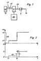
- FIG. 1 a device is shown which is provided for an internal combustion engine, in particular of a motor vehicle.
- the internal combustion engine is provided with at least one injection valve, with which fuel is injected into a combustion chamber of the internal combustion engine. On the fuel pressure is applied, which is adapted to the fuel during the compression phase of the internal combustion engine to inject into the combustion chamber.
- the injection valve has a nozzle needle which can be reciprocated in the injection valve.
- the fuel In an open state of the nozzle needle, the fuel is injected into the combustion chamber in a closed state, no fuel is injected.
- the amount of injected fuel depends on the position of the nozzle needle in the open state.
- the injection valve has a piezoelectric actuator, which is provided for adjusting the nozzle needle.
- a hydraulic coupler is provided between the actuator and the nozzle needle.
- the actuator can be acted upon by an electrical voltage, which has a change in the extent of the actuator result. This change in extent is transferred to the nozzle needle, so that the nozzle needle transitions to its open state.
- the amount of fuel injected depends on the position of the nozzle needle. This position in turn depends on the change in the extent of the actuator. The change in expansion is ultimately dependent on the change in the voltage applied to the actuator. The amount of injected fuel is thus a function of the change in the voltage applied to the actuator.
- a voltage supply UV is provided which provides at least two voltages, namely a first voltage U1 and a second voltage U2.
- a control unit SG controls a switch S, with which one of the two voltages U1, U2 is forwarded as actuator voltage UA.
- the actuator voltage UA is applied to the piezoelectric actuator A of the injector described.
- the power supply UV and the actuator A are in the FIG. 1 exemplified switched to ground.
- the actuator voltage UA is plotted over the time t. Before a time t1, the size of the actuator voltage UA is unknown. After the time t1, the actuator voltage UA has the value of the first voltage U1. After a time t2, the actuator voltage UA has the value of the second voltage U2. The difference between the first voltage U1 and the second voltage U2 corresponds to a voltage US.
- the first voltage U1 is selected to be so small that the nozzle needle of the injection valve is not moved or displaced in any case.
- the first voltage U1 thus only leads to a change in the extent of the actuator A, which optionally has a change in the state of the hydraulic coupler result.
- neither the change in the extent of the actuator A itself, nor the change in the state of the hydraulic coupler have a change in the position of the nozzle needle within the injector result.
- the first voltage U1 can be determined in particular as a function of operating variables of the internal combustion engine, for example as a function of the pressure acting on the fuel.
- the first voltage U1 can thus change over time.
- the first voltage U1 is chosen to be so large that a residual potential that may still be present in the actuator A from its last activation is exceeded in each case. Such a residual potential may arise because the actuator A is not completely discharged after being subjected to a voltage.
- the second voltage U2 is chosen as follows:
- the amount of injected fuel is a function of the change in the voltage applied to the actuator A.
- the change in the voltage applied to the actuator A is the voltage US. It is thus determined in a first step, which voltage US is required to obtain the desired amount of fuel to be injected. In a second step, this voltage US is then added to the first voltage U1. This results in the second voltage U2, which is then applied to the actuator A.
- the position E of the injector nozzle needle is plotted over time t.
- the reference character O denotes the opened state of the nozzle needle or of the injection valve and the reference symbol Z indicates the closed state.
- the exact position of the nozzle needle within the injection valve in the opened state depends on the voltage applied to the actuator A.
- the nozzle needle is in its closed state before the time t2. Especially during the period dt1 from the time t1 to the time t2, the position of the nozzle needle does not change from its closed state.
- the duration dt1 is selected such that transient phenomena that have arisen in any way within the injection valve due to the first voltage U1 of the resulting change in the extent of the actuator A and the consequent change in the state of the hydraulic coupler, in any case have largely subsided.
- the voltage US additionally applied to the actuator A at the time t2 causes the injector nozzle needle to move to its open state in accordance with the desired amount of fuel to be injected.
- This movement or adjustment of the nozzle needle is delayed due to inertia of the entire system, according to the FIG. 2 for example, after a period dt2 after time t2.
- Piezo actuators can be operated with voltage regulation, charge regulation or energy regulation. Irrespective of this, certain voltages U1, U2 are necessary in order to set a lift with a given current and an existing electrical capacitance of the actuator. The stroke is then controlled in further injection pulses to a setpoint. In this case, a certain current is impressed and it is a certain delta voltage U2-U1 and the knowledge about the voltage U1 needed.
Landscapes
- Engineering & Computer Science (AREA)
- Chemical & Material Sciences (AREA)
- Combustion & Propulsion (AREA)
- Mechanical Engineering (AREA)
- General Engineering & Computer Science (AREA)
- Fuel-Injection Apparatus (AREA)
- Electrical Control Of Air Or Fuel Supplied To Internal-Combustion Engine (AREA)
Claims (7)
- Procédé de gestion d'un moteur à combustion interne, en particulier de véhicule automobile, selon lequel
on injecte du carburant dans une chambre de combustion, à partir d'un injecteur, dont l'aiguille d'injecteur est actionnée par un actionneur (A) piézoélectrique,
un coupleur hydraulique assure le couplage entre l'actionneur (A) et l'aiguille d'injecteur, et
l'actionneur (A) est alimenté par une tension électrique pour déplacer l'aiguille d'injecteur et injecter du carburant,
caractérisé en ce que- l'actionneur (A) est alimenté par une première tension (U1) qui entraîne une modification de l'extension de l'actionneur (A), qui entraîne une modification de l'état du coupleur hydraulique mais n'entraîne aucun déplacement de l'aiguille d'injecteur,- la première tension (U1) est supérieure au potentiel résiduel de l'actionneur (A),- l'actionneur (A) est alimenté, après une durée (dt1), par une deuxième tension (U2) qui entraîne le déplacement de l'aiguille, et- la deuxième tension (U2) est sélectionnée de telle sorte que la différence entre la deuxième et la première tension (U2, U1) corresponde approximativement à la tension (US) avec laquelle l'actionneur (A) doit être commandé pour un déplacement souhaité de l'aiguille d'injecteur, pour avoir une quantité souhaitée de carburant à injecter. - Procédé selon la revendication 1,
caractérisé en ce que
la première tension (U1) est réglée en fonction des grandeurs de fonctionnement du moteur à combustion interne, notamment en fonction de la pression agissant sur le carburant. - Procédé selon l'une quelconque des revendications 1 et 2,
caractérisé en ce que
la durée (dt1) est sélectionnée de telle sorte que les phénomènes transitoires soient suffisamment amortis à l'intérieur de l'injecteur. - Programme informatique avec des commandes de programme à appliquer dans un procédé selon l'une quelconque des revendications 1 à 3, lorsqu'elles sont exécutées sur un ordinateur.
- Programme informatique selon la revendication 4,
caractérisé en ce qu'
il est stocké sur une mémoire numérique électronique, notamment une mémoire flash. - Moteur à combustion interne notamment pour un véhicule automobile comprenant :- un injecteur pour injecter du carburant dans une chambre de combustion,- une aiguille d'injecteur dans l'injecteur de carburant,- un actionneur piézoélectrique (A) pour déplacer l'aiguille d'injecteur,- un coupleur hydraulique assurant le couplage entre l'actionneur (A) et l'aiguille d'injecteur, et- un appareil de commande (SG) fournissant à l'actionneur (A) une tension électrique pour déplacer l'aiguille d'injecteur et produire ainsi l'injection de carburant,caractérisé en ce que
l'appareil de commande (SG) est réalisé pour que l'actionneur (A) reçoive une première tension (U1),- la première tension (U1) produit une variation de l'extension de l'actionneur (A),- cette variation produit une variation de l'état du coupleur hydraulique mais aucun déplacement de l'aiguille d'injecteur, et- la première tension (U1) est supérieure au potentiel résiduel de l'actionneur (A), et- après une durée (dt1) l'actionneur (A), reçoit une seconde tension (U2) produisant le déplacement de l'aiguille d'injecteur, et- la seconde tension (U2) est choisie pour que la différence entre la seconde et la première tension (U2, U1) corresponde sensiblement à la tension (US) avec laquelle l'actionneur (A) commande un déplacement souhaité de l'aiguille d'injecteur permettant d'obtenir la quantité souhaitée de carburant à injecter. - Appareil de commande pour la gestion d'un moteur à combustion interne notamment d'un véhicule automobile, selon lequel le moteur à combustion interne est équipé :- d'un injecteur pour injecter du carburant dans une chambre de combustion,- d'une aiguille d'injecteur dans l'injecteur de carburant,- d'un actionneur piézoélectrique (A) pour déplacer l'aiguille d'injecteur,- d'un coupleur hydraulique assurant le couplage entre l'actionneur (A) et l'aiguille d'injecteur, et- d'un appareil de commande (SG) fournissant à l'actionneur (A) une tension électrique pour déplacer l'aiguille d'injecteur et produire ainsi l'injection de carburant,caractérisé en ce que
l'appareil de commande (SG) est réalisé pour que l'actionneur (A) reçoive une première tension (U1),- la première tension (U1) produit une variation de l'extension de l'actionneur (A),- cette variation produit une variation de l'état du coupleur hydraulique mais aucun déplacement de l'aiguille d'injecteur, et- la première tension (U1) est supérieure au potentiel résiduel de l'actionneur (A), et- après une durée (dt1) l'actionneur (A), reçoit une seconde tension (U2) produisant le déplacement de l'aiguille d'injecteur, etla seconde tension (U2) est choisie pour que la différence entre la seconde et la première tension (U2, U1) corresponde sensiblement à la tension (US) avec laquelle l'actionneur (A) commande un déplacement souhaité de l'aiguille d'injecteur permettant d'obtenir la quantité souhaitée de carburant à injecter.
Applications Claiming Priority (2)
| Application Number | Priority Date | Filing Date | Title |
|---|---|---|---|
| DE10228063 | 2002-06-17 | ||
| DE10228063A DE10228063A1 (de) | 2002-06-17 | 2002-06-17 | Verfahren zum Betreiben einer Brennkraftmaschine insbesondere eines Kraftfahrzeugs |
Publications (3)
| Publication Number | Publication Date |
|---|---|
| EP1375882A1 EP1375882A1 (fr) | 2004-01-02 |
| EP1375882B1 EP1375882B1 (fr) | 2005-03-16 |
| EP1375882B2 true EP1375882B2 (fr) | 2008-11-19 |
Family
ID=29716623
Family Applications (1)
| Application Number | Title | Priority Date | Filing Date |
|---|---|---|---|
| EP03009204A Expired - Lifetime EP1375882B2 (fr) | 2002-06-17 | 2003-04-23 | Procédé de fonctionnement d'un moteur à combustion interne, en particulier d'automobile |
Country Status (3)
| Country | Link |
|---|---|
| EP (1) | EP1375882B2 (fr) |
| JP (1) | JP4264303B2 (fr) |
| DE (2) | DE10228063A1 (fr) |
Families Citing this family (7)
| Publication number | Priority date | Publication date | Assignee | Title |
|---|---|---|---|---|
| DE102004053349A1 (de) * | 2004-11-04 | 2006-05-18 | Siemens Ag | Verfahren und Vorrichtung zur Ansteuerung eines Kraftstoffinjektors einer Brennkraftmaschine |
| JP4363331B2 (ja) * | 2005-01-17 | 2009-11-11 | トヨタ自動車株式会社 | 燃料噴射システム |
| DE102005046933B4 (de) * | 2005-09-30 | 2015-10-15 | Continental Automotive Gmbh | Verfahren zum Ansteuern eines piezobetätigten Einspritzventils |
| DE102007014330A1 (de) * | 2007-03-26 | 2008-10-02 | Robert Bosch Gmbh | Ansteuerschaltung und Ansteuerverfahren für ein piezoelektrisches Element |
| JP2009074373A (ja) * | 2007-09-19 | 2009-04-09 | Hitachi Ltd | 内燃機関の燃料噴射制御装置 |
| EP2077312A1 (fr) | 2007-12-17 | 2009-07-08 | Nippon Oil Corporation | Carburants pour moteurs à allumage par compression de mélange homogène |
| DE102008044741B4 (de) * | 2008-08-28 | 2010-10-14 | Continental Automotive Gmbh | Verfahren und Steuergerät zum Steuern eines Injektors |
Citations (4)
| Publication number | Priority date | Publication date | Assignee | Title |
|---|---|---|---|---|
| EP0371469A2 (fr) † | 1988-11-30 | 1990-06-06 | Toyota Jidosha Kabushiki Kaisha | Appareil pour actionner un élément piézo-électrique servant à ouvrir ou fermer une partie d'une vanne |
| US5779149A (en) † | 1996-07-02 | 1998-07-14 | Siemens Automotive Corporation | Piezoelectric controlled common rail injector with hydraulic amplification of piezoelectric stroke |
| DE19921242C1 (de) † | 1999-05-07 | 2000-10-26 | Siemens Ag | Verfahren zum Positionieren des Stellantriebs in einem Kraftstoffinjektor und Vorrichtung zur Durchführung des Verfahrens |
| DE19905340C2 (de) † | 1999-02-09 | 2001-09-13 | Siemens Ag | Verfahren und Anordnung zur Voreinstellung und dynamischen Nachführung piezoelektrischer Aktoren |
Family Cites Families (5)
| Publication number | Priority date | Publication date | Assignee | Title |
|---|---|---|---|---|
| US4732129A (en) * | 1985-04-15 | 1988-03-22 | Nippon Soken, Inc. | Control apparatus for electroexpansive actuator enabling variation of stroke |
| DE19714610A1 (de) * | 1997-04-09 | 1998-10-15 | Bosch Gmbh Robert | Verfahren und Vorrichtung zum Laden und Entladen eines piezoelektrischen Elements |
| DE19903555C2 (de) * | 1999-01-29 | 2001-05-31 | Daimler Chrysler Ag | Vorrichtung zur Steuerung eines Piezoelement-Einspritzventils |
| DE19958262B4 (de) * | 1999-12-03 | 2007-03-22 | Siemens Ag | Verfahren und Vorrichtung zum Aufladen eines piezoelektrischen Aktors |
| US6420817B1 (en) * | 2000-02-11 | 2002-07-16 | Delphi Technologies, Inc. | Method for detecting injection events in a piezoelectric actuated fuel injector |
-
2002
- 2002-06-17 DE DE10228063A patent/DE10228063A1/de not_active Ceased
-
2003
- 2003-04-23 EP EP03009204A patent/EP1375882B2/fr not_active Expired - Lifetime
- 2003-04-23 DE DE50300360T patent/DE50300360D1/de not_active Expired - Lifetime
- 2003-06-17 JP JP2003172402A patent/JP4264303B2/ja not_active Expired - Fee Related
Patent Citations (4)
| Publication number | Priority date | Publication date | Assignee | Title |
|---|---|---|---|---|
| EP0371469A2 (fr) † | 1988-11-30 | 1990-06-06 | Toyota Jidosha Kabushiki Kaisha | Appareil pour actionner un élément piézo-électrique servant à ouvrir ou fermer une partie d'une vanne |
| US5779149A (en) † | 1996-07-02 | 1998-07-14 | Siemens Automotive Corporation | Piezoelectric controlled common rail injector with hydraulic amplification of piezoelectric stroke |
| DE19905340C2 (de) † | 1999-02-09 | 2001-09-13 | Siemens Ag | Verfahren und Anordnung zur Voreinstellung und dynamischen Nachführung piezoelektrischer Aktoren |
| DE19921242C1 (de) † | 1999-05-07 | 2000-10-26 | Siemens Ag | Verfahren zum Positionieren des Stellantriebs in einem Kraftstoffinjektor und Vorrichtung zur Durchführung des Verfahrens |
Non-Patent Citations (1)
| Title |
|---|
| DR.-ING. M. DORNHOLZ ET AL: "Piezoelektrisch gesteuertes Einspritzsystem zur Verbesserung d", VDI VERLAG, vol. 12, no. 182, 6 May 1993 (1993-05-06) - 7 May 1993 (1993-05-07), 14. INTERNATIONALES WIENER MOTORENSYMPOSIUM, pages 324 † |
Also Published As
| Publication number | Publication date |
|---|---|
| JP2004019666A (ja) | 2004-01-22 |
| JP4264303B2 (ja) | 2009-05-13 |
| DE50300360D1 (de) | 2005-04-21 |
| EP1375882A1 (fr) | 2004-01-02 |
| EP1375882B1 (fr) | 2005-03-16 |
| DE10228063A1 (de) | 2004-01-08 |
Similar Documents
| Publication | Publication Date | Title |
|---|---|---|
| EP1825124B1 (fr) | Procede pour commander un actionneur piezoelectrique, et unite de commande pour commander un actionneur piezoelectrique | |
| DE102013206600B4 (de) | Einspritzsystem zum Einspritzen von Kraftstoff in eine Brennkraftmaschine und Regelverfahren für ein solches Einspritzsystem | |
| WO2014131540A1 (fr) | Procédé de commande d'une opération d'injection d'un injecteur électromagnétique | |
| DE10113670A1 (de) | Verfahren und Vorrichtung zur Ansteuerung eines Piezoaktors | |
| DE102010022910B4 (de) | Verfahren und Vorrichtung zum Betreiben eines Einspritzventils | |
| WO2009010374A1 (fr) | Procédé et dispositif pour mettre en forme un signal de commande électrique pour une impulsion d'injection | |
| EP1068435B1 (fr) | Systeme d'alimentation en carburant pour un moteur a combustion interne notamment d'un vehicule automobile | |
| EP2104783B1 (fr) | Procédé de fonctionnement d'une soupape d'injection | |
| EP1375882B2 (fr) | Procédé de fonctionnement d'un moteur à combustion interne, en particulier d'automobile | |
| DE102004037255B4 (de) | Verfahren zum Betreiben einer Kraftstoffeinspritzvorrichtung insbesondere für ein Kraftfahrzeug | |
| EP1567758B1 (fr) | Procede et dispositif pour faire fonctionner un systeme d'injection d'un moteur a combustion interne | |
| WO2007028737A1 (fr) | Procede et dispositif pour faire fonctionner un actionneur piezoelectrique | |
| EP1311005B1 (fr) | Méthode et dispositif de chargement et déchargement d'un élément piézoélectrique | |
| WO2004016927A1 (fr) | Procede et dispositif pour la commande d'un actionneur | |
| EP2399016B1 (fr) | Procédé de fonctionnement d'un étage final pour au moins un piézoactionneur | |
| DE102009027290A1 (de) | Verfahren und Steuergerät zum Betreiben eines Ventils | |
| WO2007082627A2 (fr) | Procédé pour faire fonctionner un actionneur piézo-électrique, en particulier d'une soupape d'injection | |
| WO2006094700A1 (fr) | Procede et circuit de regulation de courant et de charge d'un injecteur de carburant piezo-electrique | |
| WO2011082901A1 (fr) | Procédé et dispositif de commande pour faire fonctionner une soupape | |
| WO2013110522A1 (fr) | Procédé et dispositif de commande pour charger ou décharger un actionneur piézoélectrique | |
| WO2013156377A1 (fr) | Procédé et dispositif permettant de faire fonctionner un moteur à combustion interne | |
| DE102017219568A1 (de) | Verfahren zum Steuern eines Kraftstoffinjektors | |
| DE102006004766B4 (de) | Elektrische Schaltung zum Betreiben eines Piezoaktors einer Kraftstoffeinspritzeinspritzeinrichtung einer Brennkraftmaschine | |
| DE102015212378B4 (de) | Verfahren und Vorrichtung zur Ansteuerung eines Piezoaktors eines Einspritzventils eines Kraftstoffeinspritzsystems einer Brennkraftmaschine | |
| EP1475527A2 (fr) | Procédé de commande d'un moteur à combustion interne pendant la perturbation de detection de l'angle vilebrequin |
Legal Events
| Date | Code | Title | Description |
|---|---|---|---|
| PUAI | Public reference made under article 153(3) epc to a published international application that has entered the european phase |
Free format text: ORIGINAL CODE: 0009012 |
|
| AK | Designated contracting states |
Kind code of ref document: A1 Designated state(s): AT BE BG CH CY CZ DE DK EE ES FI FR GB GR HU IE IT LI LU MC NL PT RO SE SI SK TR |
|
| AX | Request for extension of the european patent |
Extension state: AL LT LV MK |
|
| GRAP | Despatch of communication of intention to grant a patent |
Free format text: ORIGINAL CODE: EPIDOSNIGR1 |
|
| 17P | Request for examination filed |
Effective date: 20040702 |
|
| AKX | Designation fees paid |
Designated state(s): DE FR GB IT |
|
| GRAA | (expected) grant |
Free format text: ORIGINAL CODE: 0009210 |
|
| GRAS | Grant fee paid |
Free format text: ORIGINAL CODE: EPIDOSNIGR3 |
|
| AK | Designated contracting states |
Kind code of ref document: B1 Designated state(s): DE FR GB IT |
|
| REG | Reference to a national code |
Ref country code: GB Ref legal event code: FG4D Free format text: NOT ENGLISH |
|
| REG | Reference to a national code |
Ref country code: IE Ref legal event code: FG4D Free format text: GERMAN |
|
| REF | Corresponds to: |
Ref document number: 50300360 Country of ref document: DE Date of ref document: 20050421 Kind code of ref document: P |
|
| GBT | Gb: translation of ep patent filed (gb section 77(6)(a)/1977) |
Effective date: 20050711 |
|
| PLBI | Opposition filed |
Free format text: ORIGINAL CODE: 0009260 |
|
| PLAX | Notice of opposition and request to file observation + time limit sent |
Free format text: ORIGINAL CODE: EPIDOSNOBS2 |
|
| 26 | Opposition filed |
Opponent name: SIEMENS AG CT IP SV Effective date: 20051216 |
|
| ET | Fr: translation filed | ||
| PLAF | Information modified related to communication of a notice of opposition and request to file observations + time limit |
Free format text: ORIGINAL CODE: EPIDOSCOBS2 |
|
| PLBB | Reply of patent proprietor to notice(s) of opposition received |
Free format text: ORIGINAL CODE: EPIDOSNOBS3 |
|
| PLAB | Opposition data, opponent's data or that of the opponent's representative modified |
Free format text: ORIGINAL CODE: 0009299OPPO |
|
| PUAH | Patent maintained in amended form |
Free format text: ORIGINAL CODE: 0009272 |
|
| STAA | Information on the status of an ep patent application or granted ep patent |
Free format text: STATUS: PATENT MAINTAINED AS AMENDED |
|
| 27A | Patent maintained in amended form |
Effective date: 20081119 |
|
| AK | Designated contracting states |
Kind code of ref document: B2 Designated state(s): DE FR GB IT |
|
| REG | Reference to a national code |
Ref country code: FR Ref legal event code: PLFP Year of fee payment: 14 |
|
| PGFP | Annual fee paid to national office [announced via postgrant information from national office to epo] |
Ref country code: GB Payment date: 20160422 Year of fee payment: 14 |
|
| PGFP | Annual fee paid to national office [announced via postgrant information from national office to epo] |
Ref country code: IT Payment date: 20160422 Year of fee payment: 14 Ref country code: FR Payment date: 20160422 Year of fee payment: 14 |
|
| PGFP | Annual fee paid to national office [announced via postgrant information from national office to epo] |
Ref country code: DE Payment date: 20160628 Year of fee payment: 14 |
|
| REG | Reference to a national code |
Ref country code: DE Ref legal event code: R119 Ref document number: 50300360 Country of ref document: DE |
|
| GBPC | Gb: european patent ceased through non-payment of renewal fee |
Effective date: 20170423 |
|
| REG | Reference to a national code |
Ref country code: FR Ref legal event code: ST Effective date: 20171229 |
|
| PG25 | Lapsed in a contracting state [announced via postgrant information from national office to epo] |
Ref country code: DE Free format text: LAPSE BECAUSE OF NON-PAYMENT OF DUE FEES Effective date: 20171103 Ref country code: FR Free format text: LAPSE BECAUSE OF NON-PAYMENT OF DUE FEES Effective date: 20170502 |
|
| PG25 | Lapsed in a contracting state [announced via postgrant information from national office to epo] |
Ref country code: GB Free format text: LAPSE BECAUSE OF NON-PAYMENT OF DUE FEES Effective date: 20170423 |
|
| PG25 | Lapsed in a contracting state [announced via postgrant information from national office to epo] |
Ref country code: IT Free format text: LAPSE BECAUSE OF NON-PAYMENT OF DUE FEES Effective date: 20170423 |