EP1375811A2 - Befestigungsvorrichtung für eine Lamelle - Google Patents
Befestigungsvorrichtung für eine Lamelle Download PDFInfo
- Publication number
- EP1375811A2 EP1375811A2 EP03014152A EP03014152A EP1375811A2 EP 1375811 A2 EP1375811 A2 EP 1375811A2 EP 03014152 A EP03014152 A EP 03014152A EP 03014152 A EP03014152 A EP 03014152A EP 1375811 A2 EP1375811 A2 EP 1375811A2
- Authority
- EP
- European Patent Office
- Prior art keywords
- fastening device
- profile
- bolt
- holding element
- web
- Prior art date
- Legal status (The legal status is an assumption and is not a legal conclusion. Google has not performed a legal analysis and makes no representation as to the accuracy of the status listed.)
- Granted
Links
Images


Classifications
-
- E—FIXED CONSTRUCTIONS
- E06—DOORS, WINDOWS, SHUTTERS, OR ROLLER BLINDS IN GENERAL; LADDERS
- E06B—FIXED OR MOVABLE CLOSURES FOR OPENINGS IN BUILDINGS, VEHICLES, FENCES OR LIKE ENCLOSURES IN GENERAL, e.g. DOORS, WINDOWS, BLINDS, GATES
- E06B7/00—Special arrangements or measures in connection with doors or windows
- E06B7/02—Special arrangements or measures in connection with doors or windows for providing ventilation, e.g. through double windows; Arrangement of ventilation roses
- E06B7/08—Louvre doors, windows or grilles
- E06B7/084—Louvre doors, windows or grilles with rotatable lamellae
- E06B7/086—Louvre doors, windows or grilles with rotatable lamellae interconnected for concurrent movement
Definitions
- the present invention relates to a fastening device for a lamella according to the preamble of claim 1.
- a slat curtain in which the individual Slats are held pivotably on opposite sides.
- the attachment takes place via a holding element that with a front section in a Opening of the slat profile can be inserted.
- a screw which acts here as an expansion element, can be screwed in is around the front section which is quadrangular in cross section on the outside spread out and clamped down.
- This type of attachment is disadvantageous that the alignment of the slat can not always be done exactly, in particular because the front section of the holding element can be inserted into the profile with play and then jamming takes place via the expansion element.
- the insertable bolt into the receptacle of the profile Holding element at least one slot on a web on the receptacle of the profile is penetrated, wherein the holding element and the profile rotatably against each other are coupled.
- the web that can be inserted into the slot allows torsional forces to be exerted transferred particularly well from the holding element to the lamella.
- the Bridge is avoided that the material of the bolt at an extremely high Torsional load can warp, since the web acts as a kind of stop.
- Further Incorrect assembly is avoided, since the web is only in the intended Slot must be inserted so that the orientation of the holding element relative is specified for the slat. If several slots are left in the holding element incorrect assembly can be prevented if the slots are not symmetrical are arranged.
- the fixing element is in Engagement with the at least one web of the profile. This allows the fixing element not only hold on clamping forces in the recording, but will in particular also connected directly to the profile via the web to ensure stability increase.
- the fixing element is preferably held in a form-fitting manner on the web.
- the fixing element has a threaded section, which rests on an edge of the web and on the edge through the threaded section appropriate profiles are cut.
- the front edge of the profile When turning the Spreading element is thus shaped the front edge of the profile to form and To provide a non-positive connection between the fixing element and the web.
- the core diameter of the threaded section is a particularly stable attachment less than or equal to the opening in the bolt. If the Outside diameter of the threaded section larger than the inside diameter of the Opening of the bolt, the fixing element must be screwed in during assembly, which can generate particularly high clamping forces.
- the bridge acts opposite wall section of the bolt for the fixing element as a kind Counter bearing, so that the thread cuts into the web on one side and on the opposite side the thread is mostly made of plastic existing holding element deformed. This clamping intervention also ensures that accidental loosening is avoided when vibrations occur.
- the profile is preferably made of a light metal, for example aluminum manufactured, which is particularly good for slats due to its low weight suitable.
- the lamella can be formed in one or more parts, for example can be a surface element made of a transparent material on the profile be fixed.
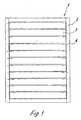
- a lamella curtain 1 which comprises a fixed frame 2, on which several pivotable slats 3 are attached.
- the slats 3 are attached to the frame 2 on opposite sides and about an axis 4 rotatably arranged.
- the frame 2 can be formed from mullion and transom profiles be mounted adjacent to a facade.
- the horizontally arranged Slats 3 are rotatably mounted in an upper area, the axis 4 can also be done in the middle or at another location.
- the slats 3 can be formed in several parts be and comprise a holding element 5, which has a U-shaped section 6.
- a retaining seal 7 for attaching a Glass pane 8 added.
- a profile web 9 is formed, which has an undercut Receiving groove for a seal 10, which at the bottom of a adjacent glass pane in the closed position.
- a strip 11 is formed on one leg of the U-shaped section 6, in a bolt 12 of a holding element 13 is received.
- the bolt 12 forms the axis 4 shown in FIG. 1.
- the holding element 13 is provided with a pin 14 at a distance from the bolt 12, which is connected to a linkage 15.
- the fastening device comprises a holding element 13, a bolt 12 and one at the opposite end Lever portion integrally formed pin 14.
- a continuous Opening 16 provided in the bolt 12
- a slot 17 is recessed in the bolt 12, in which engages a web 18 which is integrally formed on the profile 5. The web 18 stands there something into the opening 16 in the bolt 12.
- a triangular one Body 19 provided on the body 19 there is a cylindrical section 29 trained, which can be used as a bearing axis.
- a fixing element 20 in the form of a screw can be inserted into the opening 16 a front unthreaded section 21, a threaded section 22 and one Has screw head 23.
- the threaded section 2 By screwing the threaded section 2 into the Opening 16 is slightly counter to the holding element 13, in particular the bolt 12 depressed the web 18 and can thus clamp in the receptacle of the profile 5th be determined.
- the threaded portion 22 lies in particular on the Front edge of the web 18 and is screwed in there, so that a positive and non-positive Connection between the fixing element 20 and the web 18 of the profile 5 is produced.
- the holding element 13 is thus in a positive and non-positive manner the profile 5 definable.
- the outer diameter D3 of the bolt 12 is less than or equal to the diameter d3 of the receptacle 11 of the profile 5, so that the holding element 13 easily with the Bolt 12 can be inserted into the profile 5.
- the inner diameter is d2 of the bolt 12 and in the holding element 13 less than or equal to the outer thread diameter D2 of the threaded section 22.
- the screw 20 is thus inserted into the opening 16 of the holding element 13 and digs slightly into the walls of the holding element 13 made of plastic on.
- the web 18 in the slot 17 of the holding element 5 has a length L for torque transmission which, with the core diameter D1 of the screw 19, has a length which is greater than the wall thickness of the bolt 12.
- Fig. 7 shows a plan view of the fastening device in the assembled state.
- the bearing section 29 lies against the end face of the profile 5 and extends through a wall of a frame profile 2.
- the pin 14 On the lever section of the holding element 13 is formed on the pin 14, which is in engagement with a connecting piece 24, the is coupled to a linkage 25.
- the linkage 25 By moving the linkage 25 Pin 14 moves, causing the profile 5 around the bearing portion 29 on the frame profile 2 is rotated.
- the linkage 25 connects all the holding elements 13 on one side of the slat curtain and thus swivels the slats evenly.
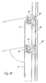
- FIG. 8 to 10 is a second embodiment of a fastening device according to the invention shown.
- a frame profile 2 ' there is a holding element 13' stored, wherein a bolt 12 'is provided, which corresponds to the previous Embodiment is formed.
- the bolt 12 ' is in turn by means of a Fixing element 23 'fixed in a receptacle of a profile 5'.
- the holding element 13 'does not comprise a pin on a lever section, but has a fork-shaped lever 14 'in which a driver 24' is received is.
- the driver 24 ' is guided on a on the frame profile 2' Push rod 25 'set.
- the push rod 25 ' is in an undercut Groove on the frame profile 2 'out.
- the profile 5 ' is formed in one piece with a lamella 3', which consists of an extruded Aluminum profile is made.
- the holding element is preferably made of plastic, but can also be made of metal, especially light metal.
- the slats 3 can one or be made in several parts and preferably consist of plastic, glass, Metal or a combination of these materials.
Landscapes
- Engineering & Computer Science (AREA)
- Civil Engineering (AREA)
- Structural Engineering (AREA)
- Connection Of Plates (AREA)
- Blinds (AREA)
- Load-Bearing And Curtain Walls (AREA)
- Gripping Jigs, Holding Jigs, And Positioning Jigs (AREA)
- Spinning Or Twisting Of Yarns (AREA)
- Paper (AREA)
- Chain Conveyers (AREA)
- Specific Sealing Or Ventilating Devices For Doors And Windows (AREA)
Abstract
Description
- Fig. 1
- eine schematische Ansicht auf einen Lamellenvorhang für eine Fassade;
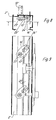
- Fig. 2
- eine geschnittene Seitenansicht auf den Lammellenvorhang der Fig. 1 mit einem ersten Ausführungsbeispiel einer erfindungsgemäßen Befestigungsvorrichtung;
- Fig. 3
- eine geschnittene Seitenansicht des Lamellenvorhangs gemäß Fig. 2 mit geöffneten Lamellen;
- Fig. 4
- eine Detailansicht der Befestigungsvorrichtung der Fig. 2 in Explosionsdarstellung;
- Fig. 5A
- eine Seitenansicht der Befestigungsvorrichtung der Fig. 2;
- Fig. 5B
- eine Detailansicht der Befestigungsvorrichtung;
- Fig. 6A und 6B
- perspektivische Ansichten des Halteelementes der Befestigungsvorrichtung;
- Fig. 7
- eine Draufsicht auf die Befestigungsvorrichtung der Fig. 2 im eingebauten Zustand;
- Fig. 8
- eine Draufsicht auf eine Befestigungsvorrichtung gemäß einem zweiten Ausführungsbeispiel;
- Fig. 9
- eine Seitenansicht der Befestigungsvorrichtung der Fig. 8, und
- Fig. 10
- eine Seitenansicht der Befestigungsvorrichtung der Fig. 9.
Claims (11)
- Befestigungsvorrichtung für eine Lamelle, insbesondere für einen Lamellenvorhang vor einer Fassade, mit einem verschwenkbaren Halteelement (13, 13'), an dem ein Bolzen (12, 12') angeformt ist, der in eine Aufnahme (11) eines Profils (5, 5') eingefügt ist, wobei in dem Bolzen (12, 12') eine Öffnung (16) zum Einstecken eines Fixierelementes (20) ausgespart ist, dadurch gekennzeichnet, dass der Bolzen (12, 12') mindestens einen Schlitz (17) aufweist, der von einem Steg (18) an der Aufnahme (11) des Profils (5, 5') durchgriffen ist und das Halteelement (13, 13') und das Profil (5, 5') drehfest aneinander gekoppelt sind.
- Befestigungsvorrichtung nach Anspruch 1, dadurch gekennzeichnet, dass das Fixierelement (20) in Eingriff mit dem mindestens einen Steg (18) des Profils (5, 5') ist.
- Befestigungsvorrichtung nach Anspruch 1 oder 2, dadurch gekennzeichnet, dass das Fixierelement (20) kraftschlüssig an dem Steg (18) gehalten ist und das Halteelement (13, 13') über das Fixierelement (20) klemmend an dem Profil (5, 5') festgelegt ist.
- Befestigungsvorrichtung nach einem der Ansprüche 1 bis 3, dadurch gekennzeichnet, dass das Fixierelement (20) einen Gewindeabschnitt (22) aufweist, der an einer Kante des Steges (18) anliegt und an der Kante durch den Gewindeabschnitt (22) entsprechende Profilierungen eingeschnitten sind.
- Befestigungsvorrichtung nach einem der Ansprüche 1 bis 4, dadurch gekennzeichnet, dass der Kerndurchmesser (D1) des Gewindeabschnittes (22) kleiner oder gleich groß zu der Öffnung (16) in dem Bolzen (12, 12') ist.
- Befestigungsvorrichtung nach einem der Ansprüche 1 bis 5, dadurch gekennzeichnet, dass der Außendurchmesser (D2) des Gewindeabschnittes (22) größer als der Innendurchmesser der Öffnung (16) des Bolzens (12, 12') ist.
- Befestigungsvorrichtung nach einem der Ansprüche 1 bis 6, dadurch gekennzeichnet, dass gegenüber dem Steg (18) ein Wandabschnitt des Bolzens (12, 12') angeordnet ist, der für das Fixierelement (20) ein Gegenlager bildet.
- Befestigungsvorrichtung nach einem der Ansprüche 1 bis 7, dadurch gekennzeichnet, dass das Profil (5, 5') aus einem Leichtmetall, vorzugsweise aus Aluminium hergestellt ist.
- Befestigungsvorrichtung nach einem der Ansprüche 1 bis 8, dadurch gekennzeichnet, dass das Profil (5, 5') als ein- oder mehrteilige verschwenkbare Lamelle zur Lichtlenkung ausgebildet ist.
- Befestigungsvorrichtung nach einem der Ansprüche 1 bis 9, dadurch gekennzeichnet, dass das Profil (5, 5') an gegenüberliegenden Seiten an einem verschwenkbaren Halteelement (13, 13') fixiert ist.
- Befestigungsvorrichtung nach einem der Ansprüche 1 bis 10, dadurch gekennzeichnet, dass an dem Halteelement (13, 13') ein Hebelabschnitt vorgesehen ist, der über ein Gestänge (25, 25') bewegbar ist.
Applications Claiming Priority (2)
| Application Number | Priority Date | Filing Date | Title |
|---|---|---|---|
| DE20209911U | 2002-06-26 | ||
| DE20209911U DE20209911U1 (de) | 2002-06-26 | 2002-06-26 | Befestigungsvorrichtung für eine Lamelle |
Publications (3)
| Publication Number | Publication Date |
|---|---|
| EP1375811A2 true EP1375811A2 (de) | 2004-01-02 |
| EP1375811A3 EP1375811A3 (de) | 2004-09-15 |
| EP1375811B1 EP1375811B1 (de) | 2006-08-09 |
Family
ID=7972572
Family Applications (1)
| Application Number | Title | Priority Date | Filing Date |
|---|---|---|---|
| EP03014152A Expired - Lifetime EP1375811B1 (de) | 2002-06-26 | 2003-06-24 | Befestigungsvorrichtung für eine Lamelle |
Country Status (5)
| Country | Link |
|---|---|
| EP (1) | EP1375811B1 (de) |
| AT (1) | ATE335909T1 (de) |
| DE (2) | DE20209911U1 (de) |
| ES (1) | ES2271429T3 (de) |
| PT (1) | PT1375811E (de) |
Families Citing this family (1)
| Publication number | Priority date | Publication date | Assignee | Title |
|---|---|---|---|---|
| DE102023108434A1 (de) * | 2023-04-03 | 2024-10-10 | Lamilux Heinrich Strunz Gmbh | Lamellenfenster |
Family Cites Families (3)
| Publication number | Priority date | Publication date | Assignee | Title |
|---|---|---|---|---|
| US4254581A (en) * | 1977-06-22 | 1981-03-10 | Norisue Ishihara | Louver shutter with movable louver boards |
| FR2707330B1 (fr) * | 1993-07-07 | 1997-05-09 | Alain Villafines | Dispositif de fermeture de fenêtre du type "Jalousie". |
| DE10103032A1 (de) * | 2001-01-24 | 2002-07-25 | Schwab Helmut | Klappladen mit horizontalen Lamellen und Lagerzapfen |
-
2002
- 2002-06-26 DE DE20209911U patent/DE20209911U1/de not_active Expired - Lifetime
-
2003
- 2003-06-24 ES ES03014152T patent/ES2271429T3/es not_active Expired - Lifetime
- 2003-06-24 EP EP03014152A patent/EP1375811B1/de not_active Expired - Lifetime
- 2003-06-24 PT PT03014152T patent/PT1375811E/pt unknown
- 2003-06-24 DE DE50304544T patent/DE50304544D1/de not_active Expired - Lifetime
- 2003-06-24 AT AT03014152T patent/ATE335909T1/de not_active IP Right Cessation
Also Published As
| Publication number | Publication date |
|---|---|
| EP1375811A3 (de) | 2004-09-15 |
| ATE335909T1 (de) | 2006-09-15 |
| DE20209911U1 (de) | 2002-08-29 |
| DE50304544D1 (de) | 2006-09-21 |
| PT1375811E (pt) | 2006-12-29 |
| ES2271429T3 (es) | 2007-04-16 |
| EP1375811B1 (de) | 2006-08-09 |
Similar Documents
| Publication | Publication Date | Title |
|---|---|---|
| EP1352134B1 (de) | Riegel-pfosten-konstruktion | |
| EP1020575B1 (de) | T-Verbindung zwischen einem Sprossen- und einem Pfostenprofil einer Fasade oder eines Lichtdaches | |
| DE9007486U1 (de) | Verbindungsformstück für Bauprofile | |
| DE9110175U1 (de) | Beschlagteil zur Klemmbefestigung in einer mindestens einseitig hinterschnittenen Profilnut | |
| DE19849152A1 (de) | Pfosten-Riegelverbindung | |
| DE102005044980B4 (de) | Stoßverbinder für Holz-/Aluminiumfassaden | |
| EP2361353A1 (de) | Beschlag zum festlegen einer leichtbauplatte | |
| DE9001277U1 (de) | Treibstangengetriebe | |
| DE19828382C2 (de) | Anordnung zum Befestigen eines einen Hohlquerschnitt aufweisenden Pfostens am Blendrahmen eines Fensters oder einer Türe aus Kunststoff oder Leichtmetall | |
| EP1223297A2 (de) | Lamelle | |
| DE20321415U1 (de) | Stützrahmenwerk für eine Fassade | |
| DE20011195U1 (de) | Halteteil für eine Fassadenverkleidung | |
| DE4210641C2 (de) | ||
| DE29514640U1 (de) | Treibstangenbeschlag für Türen, Fenster o.dgl. | |
| DE20019594U1 (de) | Justiervorrichtung eines Rahmens | |
| EP1375811B1 (de) | Befestigungsvorrichtung für eine Lamelle | |
| EP2186959B1 (de) | T-Verbindung zwischen einem Pfosten- und Riegelprofil | |
| EP0454940B1 (de) | Rahmen-Pfosten-Verbindung | |
| DE3632154C2 (de) | ||
| DE19940574C1 (de) | Anordnung zur Bildung einer Kreuzverbindung zwischen einem Längspfosten und einem Querpfosten bei einem Fenster oder einer Türe aus Kunststoff oder Leichtmetall | |
| EP0598281A1 (de) | Verbindungsanordnung für Montagebauteile, insbesondere zur Vorwandmontage von Sanitärbauteilen | |
| DE29504372U1 (de) | Verbindungssystem | |
| DE9304016U1 (de) | Schraubverbindung für Rahmenprofil-Kombinationen, insbesondere für Aluminium-Fassaden | |
| EP1039089A2 (de) | Eck- oder Kämpferverbindung für zumindest teilweise aus Holzprofilen gebildete Fenster oder Türen, Fenster- oder Türrahmen oder dergleichen | |
| DE19717119C1 (de) | Zapfenverbinder zur Stirnverbindung wenigstens eines an einer Verbindungsstelle stirnseitig endenden Holzbalkens mit einem durchlaufenden Holzbalken |
Legal Events
| Date | Code | Title | Description |
|---|---|---|---|
| PUAI | Public reference made under article 153(3) epc to a published international application that has entered the european phase |
Free format text: ORIGINAL CODE: 0009012 |
|
| AK | Designated contracting states |
Kind code of ref document: A2 Designated state(s): AT BE BG CH CY CZ DE DK EE ES FI FR GB GR HU IE IT LI LU MC NL PT RO SE SI SK TR |
|
| AX | Request for extension of the european patent |
Extension state: AL LT LV MK |
|
| PUAL | Search report despatched |
Free format text: ORIGINAL CODE: 0009013 |
|
| AK | Designated contracting states |
Kind code of ref document: A3 Designated state(s): AT BE BG CH CY CZ DE DK EE ES FI FR GB GR HU IE IT LI LU MC NL PT RO SE SI SK TR |
|
| AX | Request for extension of the european patent |
Extension state: AL LT LV MK |
|
| RIC1 | Information provided on ipc code assigned before grant |
Ipc: 7E 06B 7/086 B Ipc: 7E 06B 7/084 A |
|
| 17P | Request for examination filed |
Effective date: 20050111 |
|
| AKX | Designation fees paid |
Designated state(s): AT BE BG CH CY CZ DE DK EE ES FI FR GB GR HU IE IT LI LU MC NL PT RO SE SI SK TR |
|
| AXX | Extension fees paid |
Extension state: LT Payment date: 20050111 Extension state: LV Payment date: 20050111 |
|
| GRAP | Despatch of communication of intention to grant a patent |
Free format text: ORIGINAL CODE: EPIDOSNIGR1 |
|
| GRAS | Grant fee paid |
Free format text: ORIGINAL CODE: EPIDOSNIGR3 |
|
| GRAA | (expected) grant |
Free format text: ORIGINAL CODE: 0009210 |
|
| AK | Designated contracting states |
Kind code of ref document: B1 Designated state(s): AT BE BG CH CY CZ DE DK EE ES FI FR GB GR HU IE IT LI LU MC NL PT RO SE SI SK TR |
|
| AX | Request for extension of the european patent |
Extension state: LT LV |
|
| PG25 | Lapsed in a contracting state [announced via postgrant information from national office to epo] |
Ref country code: IT Free format text: LAPSE BECAUSE OF FAILURE TO SUBMIT A TRANSLATION OF THE DESCRIPTION OR TO PAY THE FEE WITHIN THE PRESCRIBED TIME-LIMIT;WARNING: LAPSES OF ITALIAN PATENTS WITH EFFECTIVE DATE BEFORE 2007 MAY HAVE OCCURRED AT ANY TIME BEFORE 2007. THE CORRECT EFFECTIVE DATE MAY BE DIFFERENT FROM THE ONE RECORDED. Effective date: 20060809 Ref country code: CZ Free format text: LAPSE BECAUSE OF FAILURE TO SUBMIT A TRANSLATION OF THE DESCRIPTION OR TO PAY THE FEE WITHIN THE PRESCRIBED TIME-LIMIT Effective date: 20060809 Ref country code: GB Free format text: LAPSE BECAUSE OF FAILURE TO SUBMIT A TRANSLATION OF THE DESCRIPTION OR TO PAY THE FEE WITHIN THE PRESCRIBED TIME-LIMIT Effective date: 20060809 Ref country code: FI Free format text: LAPSE BECAUSE OF FAILURE TO SUBMIT A TRANSLATION OF THE DESCRIPTION OR TO PAY THE FEE WITHIN THE PRESCRIBED TIME-LIMIT Effective date: 20060809 Ref country code: SK Free format text: LAPSE BECAUSE OF FAILURE TO SUBMIT A TRANSLATION OF THE DESCRIPTION OR TO PAY THE FEE WITHIN THE PRESCRIBED TIME-LIMIT Effective date: 20060809 Ref country code: IE Free format text: LAPSE BECAUSE OF FAILURE TO SUBMIT A TRANSLATION OF THE DESCRIPTION OR TO PAY THE FEE WITHIN THE PRESCRIBED TIME-LIMIT Effective date: 20060809 Ref country code: NL Free format text: LAPSE BECAUSE OF FAILURE TO SUBMIT A TRANSLATION OF THE DESCRIPTION OR TO PAY THE FEE WITHIN THE PRESCRIBED TIME-LIMIT Effective date: 20060809 Ref country code: RO Free format text: LAPSE BECAUSE OF FAILURE TO SUBMIT A TRANSLATION OF THE DESCRIPTION OR TO PAY THE FEE WITHIN THE PRESCRIBED TIME-LIMIT Effective date: 20060809 Ref country code: SI Free format text: LAPSE BECAUSE OF FAILURE TO SUBMIT A TRANSLATION OF THE DESCRIPTION OR TO PAY THE FEE WITHIN THE PRESCRIBED TIME-LIMIT Effective date: 20060809 |
|
| REG | Reference to a national code |
Ref country code: GB Ref legal event code: FG4D Free format text: NOT ENGLISH |
|
| REG | Reference to a national code |
Ref country code: CH Ref legal event code: EP |
|
| REG | Reference to a national code |
Ref country code: IE Ref legal event code: FG4D Free format text: LANGUAGE OF EP DOCUMENT: GERMAN |
|
| REF | Corresponds to: |
Ref document number: 50304544 Country of ref document: DE Date of ref document: 20060921 Kind code of ref document: P |
|
| PG25 | Lapsed in a contracting state [announced via postgrant information from national office to epo] |
Ref country code: SE Free format text: LAPSE BECAUSE OF FAILURE TO SUBMIT A TRANSLATION OF THE DESCRIPTION OR TO PAY THE FEE WITHIN THE PRESCRIBED TIME-LIMIT Effective date: 20061109 Ref country code: BG Free format text: LAPSE BECAUSE OF FAILURE TO SUBMIT A TRANSLATION OF THE DESCRIPTION OR TO PAY THE FEE WITHIN THE PRESCRIBED TIME-LIMIT Effective date: 20061109 Ref country code: DK Free format text: LAPSE BECAUSE OF FAILURE TO SUBMIT A TRANSLATION OF THE DESCRIPTION OR TO PAY THE FEE WITHIN THE PRESCRIBED TIME-LIMIT Effective date: 20061109 |
|
| REG | Reference to a national code |
Ref country code: PT Ref legal event code: SC4A Free format text: AVAILABILITY OF NATIONAL TRANSLATION Effective date: 20061026 |
|
| LTIE | Lt: invalidation of european patent or patent extension |
Effective date: 20060809 |
|
| NLV1 | Nl: lapsed or annulled due to failure to fulfill the requirements of art. 29p and 29m of the patents act | ||
| GBV | Gb: ep patent (uk) treated as always having been void in accordance with gb section 77(7)/1977 [no translation filed] |
Effective date: 20060809 |
|
| ET | Fr: translation filed | ||
| REG | Reference to a national code |
Ref country code: IE Ref legal event code: FD4D |
|
| REG | Reference to a national code |
Ref country code: ES Ref legal event code: FG2A Ref document number: 2271429 Country of ref document: ES Kind code of ref document: T3 |
|
| PLBE | No opposition filed within time limit |
Free format text: ORIGINAL CODE: 0009261 |
|
| STAA | Information on the status of an ep patent application or granted ep patent |
Free format text: STATUS: NO OPPOSITION FILED WITHIN TIME LIMIT |
|
| 26N | No opposition filed |
Effective date: 20070510 |
|
| BERE | Be: lapsed |
Owner name: SCHUCO INTERNATIONAL K.G. Effective date: 20070630 |
|
| PG25 | Lapsed in a contracting state [announced via postgrant information from national office to epo] |
Ref country code: MC Free format text: LAPSE BECAUSE OF NON-PAYMENT OF DUE FEES Effective date: 20070630 |
|
| REG | Reference to a national code |
Ref country code: CH Ref legal event code: PL |
|
| PG25 | Lapsed in a contracting state [announced via postgrant information from national office to epo] |
Ref country code: BE Free format text: LAPSE BECAUSE OF NON-PAYMENT OF DUE FEES Effective date: 20070630 |
|
| PG25 | Lapsed in a contracting state [announced via postgrant information from national office to epo] |
Ref country code: LI Free format text: LAPSE BECAUSE OF NON-PAYMENT OF DUE FEES Effective date: 20070630 Ref country code: GR Free format text: LAPSE BECAUSE OF FAILURE TO SUBMIT A TRANSLATION OF THE DESCRIPTION OR TO PAY THE FEE WITHIN THE PRESCRIBED TIME-LIMIT Effective date: 20061110 Ref country code: CH Free format text: LAPSE BECAUSE OF NON-PAYMENT OF DUE FEES Effective date: 20070630 |
|
| PG25 | Lapsed in a contracting state [announced via postgrant information from national office to epo] |
Ref country code: EE Free format text: LAPSE BECAUSE OF FAILURE TO SUBMIT A TRANSLATION OF THE DESCRIPTION OR TO PAY THE FEE WITHIN THE PRESCRIBED TIME-LIMIT Effective date: 20060809 |
|
| PG25 | Lapsed in a contracting state [announced via postgrant information from national office to epo] |
Ref country code: AT Free format text: LAPSE BECAUSE OF NON-PAYMENT OF DUE FEES Effective date: 20070624 |
|
| PGFP | Annual fee paid to national office [announced via postgrant information from national office to epo] |
Ref country code: PT Payment date: 20080616 Year of fee payment: 6 |
|
| PG25 | Lapsed in a contracting state [announced via postgrant information from national office to epo] |
Ref country code: LU Free format text: LAPSE BECAUSE OF NON-PAYMENT OF DUE FEES Effective date: 20070624 Ref country code: CY Free format text: LAPSE BECAUSE OF FAILURE TO SUBMIT A TRANSLATION OF THE DESCRIPTION OR TO PAY THE FEE WITHIN THE PRESCRIBED TIME-LIMIT Effective date: 20060809 |
|
| PG25 | Lapsed in a contracting state [announced via postgrant information from national office to epo] |
Ref country code: HU Free format text: LAPSE BECAUSE OF FAILURE TO SUBMIT A TRANSLATION OF THE DESCRIPTION OR TO PAY THE FEE WITHIN THE PRESCRIBED TIME-LIMIT Effective date: 20070210 Ref country code: TR Free format text: LAPSE BECAUSE OF FAILURE TO SUBMIT A TRANSLATION OF THE DESCRIPTION OR TO PAY THE FEE WITHIN THE PRESCRIBED TIME-LIMIT Effective date: 20060809 |
|
| REG | Reference to a national code |
Ref country code: PT Ref legal event code: MM4A Free format text: LAPSE DUE TO NON-PAYMENT OF FEES Effective date: 20091228 |
|
| PG25 | Lapsed in a contracting state [announced via postgrant information from national office to epo] |
Ref country code: PT Free format text: LAPSE BECAUSE OF NON-PAYMENT OF DUE FEES Effective date: 20091228 |
|
| PGFP | Annual fee paid to national office [announced via postgrant information from national office to epo] |
Ref country code: DE Payment date: 20150629 Year of fee payment: 13 Ref country code: ES Payment date: 20150625 Year of fee payment: 13 |
|
| PGFP | Annual fee paid to national office [announced via postgrant information from national office to epo] |
Ref country code: IT Payment date: 20150625 Year of fee payment: 13 |
|
| REG | Reference to a national code |
Ref country code: FR Ref legal event code: PLFP Year of fee payment: 14 |
|
| PGFP | Annual fee paid to national office [announced via postgrant information from national office to epo] |
Ref country code: FR Payment date: 20160621 Year of fee payment: 14 |
|
| REG | Reference to a national code |
Ref country code: DE Ref legal event code: R119 Ref document number: 50304544 Country of ref document: DE |
|
| PG25 | Lapsed in a contracting state [announced via postgrant information from national office to epo] |
Ref country code: DE Free format text: LAPSE BECAUSE OF NON-PAYMENT OF DUE FEES Effective date: 20170103 |
|
| PG25 | Lapsed in a contracting state [announced via postgrant information from national office to epo] |
Ref country code: IT Free format text: LAPSE BECAUSE OF NON-PAYMENT OF DUE FEES Effective date: 20160624 |
|
| REG | Reference to a national code |
Ref country code: FR Ref legal event code: ST Effective date: 20180228 |
|
| PG25 | Lapsed in a contracting state [announced via postgrant information from national office to epo] |
Ref country code: FR Free format text: LAPSE BECAUSE OF NON-PAYMENT OF DUE FEES Effective date: 20170630 Ref country code: ES Free format text: LAPSE BECAUSE OF NON-PAYMENT OF DUE FEES Effective date: 20160625 |
|
| REG | Reference to a national code |
Ref country code: ES Ref legal event code: FD2A Effective date: 20181203 |