EP1375270A2 - Windscreen wiper device, in particular for a vehicle - Google Patents
Windscreen wiper device, in particular for a vehicle Download PDFInfo
- Publication number
- EP1375270A2 EP1375270A2 EP03002435A EP03002435A EP1375270A2 EP 1375270 A2 EP1375270 A2 EP 1375270A2 EP 03002435 A EP03002435 A EP 03002435A EP 03002435 A EP03002435 A EP 03002435A EP 1375270 A2 EP1375270 A2 EP 1375270A2
- Authority
- EP
- European Patent Office
- Prior art keywords
- wiper device
- windscreen wiper
- decoupling element
- drive unit
- clamping plate
- Prior art date
- Legal status (The legal status is an assumption and is not a legal conclusion. Google has not performed a legal analysis and makes no representation as to the accuracy of the status listed.)
- Granted
Links
Images
Classifications
-
- B—PERFORMING OPERATIONS; TRANSPORTING
- B60—VEHICLES IN GENERAL
- B60S—SERVICING, CLEANING, REPAIRING, SUPPORTING, LIFTING, OR MANOEUVRING OF VEHICLES, NOT OTHERWISE PROVIDED FOR
- B60S1/00—Cleaning of vehicles
- B60S1/02—Cleaning windscreens, windows or optical devices
- B60S1/04—Wipers or the like, e.g. scrapers
- B60S1/043—Attachment of the wiper assembly to the vehicle
- B60S1/0441—Attachment of the wiper assembly to the vehicle characterised by the attachment means
- B60S1/0444—Attachment of the wiper assembly to the vehicle characterised by the attachment means comprising vibration or noise absorbing means
-
- B—PERFORMING OPERATIONS; TRANSPORTING
- B60—VEHICLES IN GENERAL
- B60S—SERVICING, CLEANING, REPAIRING, SUPPORTING, LIFTING, OR MANOEUVRING OF VEHICLES, NOT OTHERWISE PROVIDED FOR
- B60S1/00—Cleaning of vehicles
- B60S1/02—Cleaning windscreens, windows or optical devices
- B60S1/04—Wipers or the like, e.g. scrapers
- B60S1/043—Attachment of the wiper assembly to the vehicle
- B60S1/0438—Attachement of separate wiper motor assembly to the vehicle
-
- B—PERFORMING OPERATIONS; TRANSPORTING
- B60—VEHICLES IN GENERAL
- B60S—SERVICING, CLEANING, REPAIRING, SUPPORTING, LIFTING, OR MANOEUVRING OF VEHICLES, NOT OTHERWISE PROVIDED FOR
- B60S1/00—Cleaning of vehicles
- B60S1/02—Cleaning windscreens, windows or optical devices
- B60S1/56—Cleaning windscreens, windows or optical devices specially adapted for cleaning other parts or devices than front windows or windscreens
- B60S1/58—Cleaning windscreens, windows or optical devices specially adapted for cleaning other parts or devices than front windows or windscreens for rear windows
- B60S1/583—Cleaning windscreens, windows or optical devices specially adapted for cleaning other parts or devices than front windows or windscreens for rear windows including wiping devices
-
- B—PERFORMING OPERATIONS; TRANSPORTING
- B60—VEHICLES IN GENERAL
- B60S—SERVICING, CLEANING, REPAIRING, SUPPORTING, LIFTING, OR MANOEUVRING OF VEHICLES, NOT OTHERWISE PROVIDED FOR
- B60S1/00—Cleaning of vehicles
- B60S1/02—Cleaning windscreens, windows or optical devices
- B60S1/04—Wipers or the like, e.g. scrapers
- B60S1/043—Attachment of the wiper assembly to the vehicle
- B60S1/0433—Attachement of a wiper modular assembly to the vehicle
-
- B—PERFORMING OPERATIONS; TRANSPORTING
- B60—VEHICLES IN GENERAL
- B60S—SERVICING, CLEANING, REPAIRING, SUPPORTING, LIFTING, OR MANOEUVRING OF VEHICLES, NOT OTHERWISE PROVIDED FOR
- B60S1/00—Cleaning of vehicles
- B60S1/02—Cleaning windscreens, windows or optical devices
- B60S1/04—Wipers or the like, e.g. scrapers
- B60S1/043—Attachment of the wiper assembly to the vehicle
- B60S1/0441—Attachment of the wiper assembly to the vehicle characterised by the attachment means
- B60S1/045—Attachment of the wiper assembly to the vehicle characterised by the attachment means having a pre-attachment device (i.e. to hold elements in position during mounting)
Definitions
- the invention relates to a windshield wiper device, in particular for a Motor vehicle, according to the class of the independent claim.
- the Have a drive unit, which by means of a decoupling element on the Body of the motor vehicle is attached.
- the drive unit has mounting holes, usually as eyes be designated. These are of rubber sleeves as decoupling elements enclosed. The drive unit is pulled by means of screws through the eyes are attached to the body of the motor vehicle.
- the windshield wiper device according to the invention with the features of Main claim has the advantage that the drive unit a nozzle is provided, the is insertable into the decoupling element. This will add the number of parts reduced the installation of the windscreen wiper device and the condition for a standardized drive created. Furthermore, in this way the positioning the drive in the vehicle simplified and the noise decoupling can be improved. In addition, such a unified interface for a variety of Vehicle types are created.
- the drive unit has an output shaft which the decoupling element in the assembled position passes through. In this way are none additional threaded rods or holes in the body required, the vehicle-specific must be adjusted.
- a particularly simple realization is achieved in that the neck the Includes output shaft radially.
- a particularly good torque support is through achieved an asymmetric design of the neck.
- the neck has lugs which are provided with recesses of the Decoupling element cooperate such that a positive connection arises. This increases the stability and the torque support of the attachment.
- a particularly advantageous embodiment can be achieved by a clamping plate, the can be fastened on one end face of the neck.
- the drive unit is this way particularly sturdily attachable to the vehicle body.
- the decoupling and thus the damping is particularly pronounced when the Decoupling element between the nozzle and clamping plate is arranged. Further this is improved by a firm clamping of the decoupling element between Clamping plate and socket.
- the clamping plate has notches, which with further recesses of Decoupling element can work together, is a higher Torque support achieved.
- the attachment is improved by that the height of the nozzle is smaller than the thickness of the decoupling element.
- this results in an improved noise decoupling and a cost-optimized Solution.
- the clamping plate can be screwed to the nozzle Fasten. Welding, spot welding or riveting is of course also possible.
- a particularly accurate positioning can be achieved in that the Drive unit having a first centering, which with a second centering the Clamping plate cooperates.
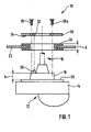
- FIG. 1 shows a windshield wiper device 10 according to the invention schematic representation shown.
- This includes a drive unit 12 with a Housing 14 from which an output shaft 16 protrudes.
- the housing 14 has a connection 18 on, which protrudes from a substantially flat surface 20 of the housing 14.
- the Output shaft 16 is arranged approximately in the center of the drive unit 12 and is annularly covered by the nozzle 18.
- This Decoupling element 24 is a circular ring made of an elastomer, so for example Rubber formed, and along its outer circumferential surface cut in such a way that a rotational body with a cross-sectionally U-shaped profile is formed.
- the Decoupling element 24 is inserted into the body panel 22, so that the sheet in the Interior of the U-shaped profile protrudes.
- the thickness d of the decoupling element 24 is a little larger than the height h of the nozzle 18.
- a clamping plate 26 is arranged, which has an opening for the Output shaft 16 has and further two holes for two screws 28, 28a has, with the clamping plate 26 can be screwed to the nozzle 18.
- the drive unit 12 has a first centering aid 30, which is designed as a simple centering pin. With this pin 30 now has a hole 32 as a second centering together, which is provided in the clamping plate 26.
- a Notch 34 is provided, which, in the assembled state, in the Decoupling element 24 pushes in and in this way the Torque transmission improved.
- a windshield wiper arm is then operatively connected, the one Wiper blade carries. This is omitted in the figure for clarity.
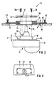
- FIG. 2 shows a variation of the windshield wiper device 10 according to the invention Figure 1 shown.
- the drive unit 12 with the housing 14, the nozzle 18 and the output shaft 16 are again inserted into the decoupling element 24.
- the Decoupling element 24 is not supported by the body panel 22, but is used in a carrier element 36.
- This support member 36 may be a simple Sheet metal piece or can also be used as a plastic part in one piece with the Be decoupling element formed. Of course, a separate training is also off two plastic parts conceivable.
- the carrier element 36 is connected to the body panel 22 connected, which be realized for example as a screw, rivet or welded connection can.
- FIG. 2 shows a variation of the windshield wiper device 10 according to the invention Figure 1 shown.
- FIG. 3 shows the windshield wiper device according to the invention from FIG. 2 in one Top view shown.
- the body panel 22 has a U-shaped recess 38, in which the carrier element 36 is inserted.
- the carrier element is by means of a Screw 40 secured to the body panel 22.
- the wiper arm with the wiper blade, the at least indirectly is in operative connection with the output shaft 16.
- the nozzle 18 may, for example, also lugs 42 having recesses 44th of the decoupling element 24 cooperate and so the torque stability of Improve windscreen wiper device. This can also be due to an asymmetric Training the nozzle 18 can be achieved.
Landscapes
- Engineering & Computer Science (AREA)
- Mechanical Engineering (AREA)
- Body Structure For Vehicles (AREA)
- Connection Of Motors, Electrical Generators, Mechanical Devices, And The Like (AREA)
- Rear-View Mirror Devices That Are Mounted On The Exterior Of The Vehicle (AREA)
Abstract
Description
Die Erfindung betrifft eine Scheibenwischvorrichtung, insbesondere für ein Kraftfahrzeug, nach Gattung des unabhängigen Anspruchs.The invention relates to a windshield wiper device, in particular for a Motor vehicle, according to the class of the independent claim.
Es sind schon zahlreichen Scheibenwischvorrichtungen für Kraftfahrzeuge bekannt, die ein Antriebsaggregat aufweisen, welches mittels eines Entkopplungselementes an der Karosserie des Kraftfahrzeuges befestigt ist. Bei derartigen Scheibenwischvorrichtungen weist das Antriebsaggregat Befestigungsöffnungen auf, die üblicherweise als Augen bezeichnet werden. Diese sind von Gummimuffen als Entkopplungselemente umschlossen. Das Antriebsaggregat wird mittels Schrauben, die durch die Augen gezogen sind, an der Karosserie des Kraftfahrzeugs befestigt.There are already numerous windscreen wiper devices for motor vehicles known, the Have a drive unit, which by means of a decoupling element on the Body of the motor vehicle is attached. In such windshield wiper devices The drive unit has mounting holes, usually as eyes be designated. These are of rubber sleeves as decoupling elements enclosed. The drive unit is pulled by means of screws through the eyes are attached to the body of the motor vehicle.
Weiterhin ist bekannt, an der Karosserie Gewindestangen zu befestigen, auf die das Antriebsaggregat aufgesteckt ist und mittels entsprechender Muttern gesichert wird.Furthermore, it is known to attach to the body threaded rods on which the Drive unit is attached and secured by means of appropriate nuts.
Bei derartigen Scheibenwischvorrichtungen ist jedoch ein hoher Aufwand bei der Auslegung notwendig, da die Augen des Antriebsaggregats und die Befestigungspunkte im Kraftfahrzeug fahrzeugspezifisch sehr unterschiedlich sind. Dadurch ist die Montage der Scheibenwischvorrichtung im Kraftfahrzeug sehr komplex und die Applikation auf das jeweilige Fahrzeug sehr aufwändig. In such windshield wiper devices, however, a high cost in the Design necessary, as the eyes of the drive unit and the attachment points are very different vehicle specific in the vehicle. This is the assembly the windscreen wiper device in the motor vehicle very complex and the application the respective vehicle very expensive.
Die erfindungsgemäße Scheibenwischvorrichtung mit den Merkmalen des Hauptanspruchs hat den Vorteil, dass am Antriebsaggregat ein Stutzen vorgesehen ist, der in das Entkopplungselement einführbar ist. Auf diese Weise wird die Anzahl der Teile bei der Montage der Scheibenwischvorrichtung reduziert und die Voraussetzung für einen standardisierten Antrieb geschaffen. Weiterhin kann auf diese Weise die Positionierung des Antriebs im Fahrzeug vereinfacht und die Geräuschentkopplung verbessert werden. Darüber hinaus kann so eine einheitliche Schnittstelle für eine Vielzahl von Fahrzeugtypen geschaffen werden.The windshield wiper device according to the invention with the features of Main claim has the advantage that the drive unit a nozzle is provided, the is insertable into the decoupling element. This will add the number of parts reduced the installation of the windscreen wiper device and the condition for a standardized drive created. Furthermore, in this way the positioning the drive in the vehicle simplified and the noise decoupling can be improved. In addition, such a unified interface for a variety of Vehicle types are created.
Durch die in den Unteransprüchen aufgeführten Maßnahmen ergeben sich vorteilhafte Weiterbildungen und Verbesserungen der im Hauptanspruch angegebenen Merkmale.The measures listed in the dependent claims are advantageous Further developments and improvements of the main claim features.
Besonders vorteilhaft ist es, wenn das Antriebsaggregat eine Abtriebswelle aufweist, die das Entkopplungselement in montierter Lage durchgreift. Auf diese Weise sind keine weiteren Gewindestangen oder Bohrungen in der Karosserie erforderlich, die fahrzeugspezifisch angepasst werden müssen.It is particularly advantageous if the drive unit has an output shaft which the decoupling element in the assembled position passes through. In this way are none additional threaded rods or holes in the body required, the vehicle-specific must be adjusted.
Eine besonders einfache Realisierung wird dadurch erreicht, dass der Stutzen die Abtriebswelle radial umfasst. Eine besonders gute Drehmomentenabstützung wird durch eine asymmetrische Ausbildung des Stutzens erzielt.A particularly simple realization is achieved in that the neck the Includes output shaft radially. A particularly good torque support is through achieved an asymmetric design of the neck.
Besonders vorteilhaft ist es, wenn der Stutzen Nasen aufweist, die mit Aussparungen des Entkopplungselementes derart zusammenwirken, dass eine formschlüssige Verbindung entsteht. Dies erhöht die Stabilität und die Drehmomentenabstützung der Befestigung.It is particularly advantageous if the neck has lugs which are provided with recesses of the Decoupling element cooperate such that a positive connection arises. This increases the stability and the torque support of the attachment.
Eine besonders vorteilhafte Ausführung kann durch eine Spannplatte erzielt werden, die auf einer Stirnseite des Stutzens befestigbar ist. Das Antriebsaggregat ist auf diese Weise besonders stabil an der Fahrzeugkarosserie befestigbar.A particularly advantageous embodiment can be achieved by a clamping plate, the can be fastened on one end face of the neck. The drive unit is this way particularly sturdily attachable to the vehicle body.
Die Entkopplung und damit die Dämpfung ist besonders ausgeprägt, wenn das Entkopplungselement zwischen Stutzen und Spannplatte angeordnet ist. Weiter verbessert wird dies durch ein festes Einklemmen des Entkopplungselements zwischen Spannplatte und Stutzen. The decoupling and thus the damping is particularly pronounced when the Decoupling element between the nozzle and clamping plate is arranged. Further this is improved by a firm clamping of the decoupling element between Clamping plate and socket.
Wenn die Spannplatte Ausklinkungen aufweist, die mit weiteren Aussparungen des Entkopplungselementes zusammenwirken können, wird eine höhere Drehmomentenabstützung erzielt. Weiter verbessert wird die Befestigung dadurch, dass die Höhe des Stutzens kleiner als die Dicke des Entkopplungselementes ist. Darüber hinaus ergibt sich so eine verbesserte Geräuschentkopplung und eine kostenoptimierte Lösung.If the clamping plate has notches, which with further recesses of Decoupling element can work together, is a higher Torque support achieved. Next, the attachment is improved by that the height of the nozzle is smaller than the thickness of the decoupling element. About that In addition, this results in an improved noise decoupling and a cost-optimized Solution.
In besonders einfacher Weise lässt sich die Spannplatte am Stutzen durch Anschrauben befestigen. Schweißen, Punktschweißen oder Nieten ist natürlich auch möglich.In a particularly simple manner, the clamping plate can be screwed to the nozzle Fasten. Welding, spot welding or riveting is of course also possible.
Eine besonders genaue Positionierung kann dadurch erreicht werden, dass das Antriebsaggregat eine erste Zentrierhilfe aufweist, die mit einer zweiten Zentrierhilfe der Spannplatte zusammenwirkt.A particularly accurate positioning can be achieved in that the Drive unit having a first centering, which with a second centering the Clamping plate cooperates.
Ausführungsbeispiele der Erfindung sind in den Zeichnungen dargestellt und in der
nachfolgenden Beschreibung näher erläutert. Es zeigen
In Figur 1 ist eine erfindungsgemäße Scheibenwischvorrichtung 10 in einer
schematischen Darstellung gezeigt. Diese umfasst ein Antriebsaggregat 12 mit einem
Gehäuse 14, aus dem eine Abtriebswelle 16 ragt. Das Gehäuse 14 weist einen Stutzen 18
auf, der aus einer im wesentlichen ebenen Fläche 20 des Gehäuses 14 hervorragt. Die
Abtriebswelle 16 ist dabei etwa im Zentrum des Antriebsaggregats 12 angeordnet und
wird vom Stutzen 18 ringförmig umfasst. Am Karosserieblech 22 des Kraftfahrzeugs
(nicht gezeichnet) ist ein Entkopplungselement 24 eingesetzt. Dieses
Entkopplungselement 24 ist als Kreisring aus einem Elastomer, also beispielsweise aus
Gummi ausgebildet, und entlang seiner äußeren Mantelfläche derart eingeschnitten, dass
ein Rotationskörper mit einem im Querschnitt U-förmigen Profil entsteht. Das
Entkopplungselement 24 ist in das Karosserieblech 22 eingesetzt, sodass das Blech in das
Innere des U-förmigen Profils hineinragt. Die Dicke d des Entkopplungselements 24 ist
dabei etwas größer als die Höhe h des Stutzens 18.FIG. 1 shows a
Zur endgültigen Befestigung ist auf der dem Antriebsaggregat 12 abgewandten Seite des
Entkopplungselements 24 eine Spannplatte 26 angeordnet, die über eine Öffnung für die
Abtriebswelle 16 verfügt und weiterhin zwei Bohrungen für zwei Schrauben 28, 28a
aufweist, mit der die Spannplatte 26 am Stutzen 18 festgeschraubt werden kann. Zur
genaueren Positionierung weist das Antriebsaggregat 12 eine erste Zentrierhilfe 30 auf,
die als einfacher Zentrierstift ausgebildet ist. Mit diesem Stift 30 wirkt nun eine Bohrung
32 als zweite Zentrierhilfe zusammen, die in der Spannplatte 26 vorgesehen ist. Natürlich
kann auch das Entkopplungselement 24 über eine derartige Zentrierhilfe verfügen, die in
Kombination auch mit der ersten oder zweiten Zentrierhilfe 30, 32 zusammenwirken
kann. Zur Verbesserung der Drehmomentenstabilität ist an der Spannplatte 26 eine
Ausklinkung 34 vorgesehen, die sich, in montiertem Zustand, in das
Entkopplungselement 24 hineindrückt und auf diese Weise die
Drehmomentenübertragung verbessert.For final attachment is on the
An der Abtriebswelle 16 ist dann ein Scheibenwischerarm wirkverbunden, der ein
Wischblatt trägt . Dies ist in der Figur der Übersichtlichkeit wegen weggelassen.On the
In Figur 2 ist eine Variation der erfindungsgemäßen Scheibenwischvorrichtung 10 nach
Figur 1 dargestellt. Das Antriebsaggregat 12 mit dem Gehäuse 14, dem Stutzen 18 und
der Abtriebswelle 16 sind wieder in das Entkopplungselement 24 eingefügt. Das
Entkopplungselement 24 wird jedoch nicht vom Karosserieblech 22 getragen, sondern ist
in ein Trägerelement 36 eingesetzt. Dieses Trägerelement 36 kann ein einfaches
Blechstück sein oder kann auch als Kunststoffteil einstückig mit dem
Entkopplungselement ausgebildet sein. Natürlich ist auch eine separate Ausbildung aus
zwei Kunststoffteilen denkbar. Das Trägerelement 36 ist mit dem Karosserieblech 22
verbunden, was beispielsweise als Schraub-, Niet- oder Schweißverbindung realisiert sein
kann. Selbstverständlich sind auch Kombinationen der in Figur 1 und Figur 2
dargestellten Varianten möglich.FIG. 2 shows a variation of the
In Figur 3 ist die erfindungsgemäße Scheibenwischvorrichtung aus Figur 2 in einer
Draufsicht dargestellt. Das Karosserieblech 22 weist eine U-förmige Aussparung 38 auf,
in die das Trägerelement 36 eingesetzt ist. Das Trägerelement ist mittels einer
Schraubverbindung 40 am Karosserieblech 22 befestigt. Nicht gezeichnet ist in dieser
Darstellung, wie auch in den Figuren 1 und 2, der Wischerarm mit dem Wischblatt, das
zumindest mittelbar mit der Abtriebswelle 16 in Wirkverbindung steht.FIG. 3 shows the windshield wiper device according to the invention from FIG. 2 in one
Top view shown. The
Der Stutzen 18 kann beispielsweise auch Nasen 42 aufweisen, die mit Aussparungen 44
des Entkopplungselementes 24 zusammenwirken und so die Drehmomentenstabilität der
Scheibenwischvorrichtung verbessern. Dies kann auch durch eine asymmetrische
Ausbildung des Stutzens 18 erzielt werden. So kann der Stutzen 18 beispielsweise
ellipsenförmig, aber auch quadratisch oder achteckig ausgebildet sein; "asymmetrisch" ist
hier im Sinne von nicht kreissymmetrisch zu verstehen. Dementsprechend ist natürlich
auch das Entkopplungselement 24 geformt. In einer weiteren Variation ist es auch
möglich, den Stutzen 18 beispielsweise sechs- oder achteckig auszubilden und in ein
Entkopplungselement 24 einzufügen, dessen Innenform zylindrisch und damit kreisrund
ist.The
Claims (11)
Applications Claiming Priority (2)
| Application Number | Priority Date | Filing Date | Title |
|---|---|---|---|
| DE10229196 | 2002-06-28 | ||
| DE2002129196 DE10229196A1 (en) | 2002-06-28 | 2002-06-28 | Windscreen wiper device, in particular for a motor vehicle |
Publications (3)
| Publication Number | Publication Date |
|---|---|
| EP1375270A2 true EP1375270A2 (en) | 2004-01-02 |
| EP1375270A3 EP1375270A3 (en) | 2005-03-09 |
| EP1375270B1 EP1375270B1 (en) | 2007-02-14 |
Family
ID=29716719
Family Applications (1)
| Application Number | Title | Priority Date | Filing Date |
|---|---|---|---|
| EP20030002435 Expired - Lifetime EP1375270B1 (en) | 2002-06-28 | 2003-02-05 | Windscreen wiper device, in particular for a vehicle |
Country Status (3)
| Country | Link |
|---|---|
| EP (1) | EP1375270B1 (en) |
| DE (2) | DE10229196A1 (en) |
| ES (1) | ES2280634T3 (en) |
Cited By (3)
| Publication number | Priority date | Publication date | Assignee | Title |
|---|---|---|---|---|
| WO2007048677A1 (en) | 2005-10-24 | 2007-05-03 | Robert Bosch Gmbh | Electric motor with fixing adapter |
| WO2007073954A1 (en) * | 2005-12-22 | 2007-07-05 | Robert Bosch Gmbh | Window wiper system for a vehicle, in particular a rear window wiper system for a motor vehicle |
| US10562498B2 (en) * | 2017-07-31 | 2020-02-18 | Zhejiang CFMOTO Power Co., Ltd. | ATV windshield and wiper mounting |
Families Citing this family (3)
| Publication number | Priority date | Publication date | Assignee | Title |
|---|---|---|---|---|
| DE102008045105A1 (en) | 2008-08-29 | 2010-03-04 | Volkswagen Ag | Fastening arrangement for rear window wiper arrangement at vehicle, has seal arranged between windowpane and assembly plate, and fastening nuts screwed to bolts in vehicle inner side, and deforming drive device with windowpane and plate |
| DE102009045338B4 (en) * | 2009-10-05 | 2017-08-24 | Robert Bosch Gmbh | Windshield wiper device |
| FR3067311B1 (en) * | 2017-06-09 | 2019-07-19 | Valeo Systemes D'essuyage | FIXING DEVICE FOR WIPING ACTUATOR PIPING SYSTEM |
Citations (3)
| Publication number | Priority date | Publication date | Assignee | Title |
|---|---|---|---|---|
| DE3209278A1 (en) * | 1982-03-13 | 1983-09-15 | SWF-Spezialfabrik für Autozubehör Gustav Rau GmbH, 7120 Bietigheim-Bissingen | Cleaning system for the rear window of a motor vehicle |
| JPH10167021A (en) * | 1996-12-12 | 1998-06-23 | Nissan Motor Co Ltd | Installation structure for rear wiper motor |
| JPH10329658A (en) * | 1997-05-29 | 1998-12-15 | Nissan Motor Co Ltd | Mounting structure of wiper device |
-
2002
- 2002-06-28 DE DE2002129196 patent/DE10229196A1/en not_active Ceased
-
2003
- 2003-02-05 DE DE50306473T patent/DE50306473D1/en not_active Expired - Lifetime
- 2003-02-05 ES ES03002435T patent/ES2280634T3/en not_active Expired - Lifetime
- 2003-02-05 EP EP20030002435 patent/EP1375270B1/en not_active Expired - Lifetime
Patent Citations (3)
| Publication number | Priority date | Publication date | Assignee | Title |
|---|---|---|---|---|
| DE3209278A1 (en) * | 1982-03-13 | 1983-09-15 | SWF-Spezialfabrik für Autozubehör Gustav Rau GmbH, 7120 Bietigheim-Bissingen | Cleaning system for the rear window of a motor vehicle |
| JPH10167021A (en) * | 1996-12-12 | 1998-06-23 | Nissan Motor Co Ltd | Installation structure for rear wiper motor |
| JPH10329658A (en) * | 1997-05-29 | 1998-12-15 | Nissan Motor Co Ltd | Mounting structure of wiper device |
Non-Patent Citations (2)
| Title |
|---|
| PATENT ABSTRACTS OF JAPAN Bd. 1998, Nr. 11, 30. September 1998 (1998-09-30) -& JP 10 167021 A (NISSAN MOTOR CO LTD), 23. Juni 1998 (1998-06-23) * |
| PATENT ABSTRACTS OF JAPAN Bd. 1999, Nr. 03, 31. März 1999 (1999-03-31) -& JP 10 329658 A (NISSAN MOTOR CO LTD), 15. Dezember 1998 (1998-12-15) * |
Cited By (3)
| Publication number | Priority date | Publication date | Assignee | Title |
|---|---|---|---|---|
| WO2007048677A1 (en) | 2005-10-24 | 2007-05-03 | Robert Bosch Gmbh | Electric motor with fixing adapter |
| WO2007073954A1 (en) * | 2005-12-22 | 2007-07-05 | Robert Bosch Gmbh | Window wiper system for a vehicle, in particular a rear window wiper system for a motor vehicle |
| US10562498B2 (en) * | 2017-07-31 | 2020-02-18 | Zhejiang CFMOTO Power Co., Ltd. | ATV windshield and wiper mounting |
Also Published As
| Publication number | Publication date |
|---|---|
| DE10229196A1 (en) | 2004-01-15 |
| ES2280634T3 (en) | 2007-09-16 |
| DE50306473D1 (en) | 2007-03-29 |
| EP1375270A3 (en) | 2005-03-09 |
| EP1375270B1 (en) | 2007-02-14 |
Similar Documents
| Publication | Publication Date | Title |
|---|---|---|
| EP1735194B1 (en) | Windshield wiper, especially for a motor vehicle | |
| EP1713669B1 (en) | Window wiping device, particularly for a motor vehicle | |
| EP0892724B2 (en) | Fastening device | |
| EP1291254B1 (en) | Windscreen wiper device | |
| WO2004113135A1 (en) | Wiper device, especially for a motor vehicle | |
| EP1610988B1 (en) | Electric drive unit | |
| WO2005075265A1 (en) | Windscreen wiping device, particularly for a motor vehicle | |
| EP1735193B1 (en) | Windshield wiper, especially for a motor vehicle | |
| EP1375270B1 (en) | Windscreen wiper device, in particular for a vehicle | |
| WO2012098108A1 (en) | Plate coupling | |
| WO2003051690A1 (en) | Windscreen wiping device with a fixing part | |
| EP0714357B1 (en) | Fixture for windshield wipers | |
| EP1795754B1 (en) | Universal flange | |
| DE102005056209A1 (en) | Pre-mounted component e.g. electric motor, for motor vehicle, has clamping piece serving as connecting unit for connecting units together, where piece has flange, which is radially aligned outwards at ends | |
| EP2006171A2 (en) | Windscreen wiper actuator assembly | |
| DE3148525A1 (en) | Adjustable exterior rearview mirror | |
| DE10328657B4 (en) | Rear-view mirror arrangement with rear-view mirror pivoting part | |
| EP0935545A1 (en) | Wiper system | |
| EP1663739B1 (en) | Windscreen wiper device in particular for a motor vehicle | |
| DE112020000951T5 (en) | Shock absorbers | |
| EP2067672B1 (en) | Windscreen wiper device for a motor vehicle | |
| DE10301900A1 (en) | Windscreen wiper arrangement, especially for motor vehicle, has at least two essentially elongated, axially rigidly mounted attachment elements that can engage in openings in motor vehicle | |
| DE10232877A1 (en) | Windscreen wiper device, in particular for a motor vehicle | |
| DE102009054711A1 (en) | Windshield wiper device | |
| DE102010019926A1 (en) | Fastening arrangement for use in motor vehicle, has fastening element brought into position in which element is engaged to openings, where changing of distance of openings is caused through rotation of fastening element around axis |
Legal Events
| Date | Code | Title | Description |
|---|---|---|---|
| PUAI | Public reference made under article 153(3) epc to a published international application that has entered the european phase |
Free format text: ORIGINAL CODE: 0009012 |
|
| AK | Designated contracting states |
Kind code of ref document: A2 Designated state(s): AT BE BG CH CY CZ DE DK EE ES FI FR GB GR HU IE IT LI LU MC NL PT SE SI SK TR |
|
| AX | Request for extension of the european patent |
Extension state: AL LT LV MK RO |
|
| PUAL | Search report despatched |
Free format text: ORIGINAL CODE: 0009013 |
|
| AK | Designated contracting states |
Kind code of ref document: A3 Designated state(s): AT BE BG CH CY CZ DE DK EE ES FI FR GB GR HU IE IT LI LU MC NL PT SE SI SK TR |
|
| AX | Request for extension of the european patent |
Extension state: AL LT LV MK RO |
|
| 17P | Request for examination filed |
Effective date: 20050909 |
|
| AKX | Designation fees paid |
Designated state(s): DE ES FR GB IT |
|
| GRAP | Despatch of communication of intention to grant a patent |
Free format text: ORIGINAL CODE: EPIDOSNIGR1 |
|
| GRAS | Grant fee paid |
Free format text: ORIGINAL CODE: EPIDOSNIGR3 |
|
| GRAA | (expected) grant |
Free format text: ORIGINAL CODE: 0009210 |
|
| AK | Designated contracting states |
Kind code of ref document: B1 Designated state(s): DE ES FR GB IT |
|
| REG | Reference to a national code |
Ref country code: GB Ref legal event code: FG4D Free format text: NOT ENGLISH |
|
| REF | Corresponds to: |
Ref document number: 50306473 Country of ref document: DE Date of ref document: 20070329 Kind code of ref document: P |
|
| GBT | Gb: translation of ep patent filed (gb section 77(6)(a)/1977) |
Effective date: 20070509 |
|
| ET | Fr: translation filed | ||
| REG | Reference to a national code |
Ref country code: ES Ref legal event code: FG2A Ref document number: 2280634 Country of ref document: ES Kind code of ref document: T3 |
|
| PLBE | No opposition filed within time limit |
Free format text: ORIGINAL CODE: 0009261 |
|
| STAA | Information on the status of an ep patent application or granted ep patent |
Free format text: STATUS: NO OPPOSITION FILED WITHIN TIME LIMIT |
|
| 26N | No opposition filed |
Effective date: 20071115 |
|
| PG25 | Lapsed in a contracting state [announced via postgrant information from national office to epo] |
Ref country code: IT Free format text: LAPSE BECAUSE OF NON-PAYMENT OF DUE FEES Effective date: 20080205 |
|
| PGFP | Annual fee paid to national office [announced via postgrant information from national office to epo] |
Ref country code: IT Payment date: 20150223 Year of fee payment: 13 |
|
| PGFP | Annual fee paid to national office [announced via postgrant information from national office to epo] |
Ref country code: GB Payment date: 20150223 Year of fee payment: 13 |
|
| REG | Reference to a national code |
Ref country code: FR Ref legal event code: PLFP Year of fee payment: 14 |
|
| GBPC | Gb: european patent ceased through non-payment of renewal fee |
Effective date: 20160205 |
|
| PG25 | Lapsed in a contracting state [announced via postgrant information from national office to epo] |
Ref country code: IT Free format text: LAPSE BECAUSE OF NON-PAYMENT OF DUE FEES Effective date: 20160205 |
|
| PG25 | Lapsed in a contracting state [announced via postgrant information from national office to epo] |
Ref country code: GB Free format text: LAPSE BECAUSE OF NON-PAYMENT OF DUE FEES Effective date: 20160205 |
|
| REG | Reference to a national code |
Ref country code: FR Ref legal event code: PLFP Year of fee payment: 15 |
|
| PGFP | Annual fee paid to national office [announced via postgrant information from national office to epo] |
Ref country code: FR Payment date: 20170220 Year of fee payment: 15 |
|
| PGFP | Annual fee paid to national office [announced via postgrant information from national office to epo] |
Ref country code: ES Payment date: 20170220 Year of fee payment: 15 |
|
| PGFP | Annual fee paid to national office [announced via postgrant information from national office to epo] |
Ref country code: DE Payment date: 20170427 Year of fee payment: 15 |
|
| REG | Reference to a national code |
Ref country code: DE Ref legal event code: R119 Ref document number: 50306473 Country of ref document: DE |
|
| REG | Reference to a national code |
Ref country code: FR Ref legal event code: ST Effective date: 20181031 |
|
| PG25 | Lapsed in a contracting state [announced via postgrant information from national office to epo] |
Ref country code: DE Free format text: LAPSE BECAUSE OF NON-PAYMENT OF DUE FEES Effective date: 20180901 |
|
| PG25 | Lapsed in a contracting state [announced via postgrant information from national office to epo] |
Ref country code: FR Free format text: LAPSE BECAUSE OF NON-PAYMENT OF DUE FEES Effective date: 20180228 |
|
| REG | Reference to a national code |
Ref country code: ES Ref legal event code: FD2A Effective date: 20190801 |
|
| PG25 | Lapsed in a contracting state [announced via postgrant information from national office to epo] |
Ref country code: ES Free format text: LAPSE BECAUSE OF NON-PAYMENT OF DUE FEES Effective date: 20180206 |