EP1375233A1 - Pédale d'accélérateur à contrôle de force de rappel intégré - Google Patents
Pédale d'accélérateur à contrôle de force de rappel intégré Download PDFInfo
- Publication number
- EP1375233A1 EP1375233A1 EP03350003A EP03350003A EP1375233A1 EP 1375233 A1 EP1375233 A1 EP 1375233A1 EP 03350003 A EP03350003 A EP 03350003A EP 03350003 A EP03350003 A EP 03350003A EP 1375233 A1 EP1375233 A1 EP 1375233A1
- Authority
- EP
- European Patent Office
- Prior art keywords
- pedal
- return force
- accelerator pedal
- spring
- force control
- Prior art date
- Legal status (The legal status is an assumption and is not a legal conclusion. Google has not performed a legal analysis and makes no representation as to the accuracy of the status listed.)
- Granted
Links
Images


Classifications
-
- G—PHYSICS
- G05—CONTROLLING; REGULATING
- G05G—CONTROL DEVICES OR SYSTEMS INSOFAR AS CHARACTERISED BY MECHANICAL FEATURES ONLY
- G05G1/00—Controlling members, e.g. knobs or handles; Assemblies or arrangements thereof; Indicating position of controlling members
- G05G1/30—Controlling members actuated by foot
-
- B—PERFORMING OPERATIONS; TRANSPORTING
- B60—VEHICLES IN GENERAL
- B60K—ARRANGEMENT OR MOUNTING OF PROPULSION UNITS OR OF TRANSMISSIONS IN VEHICLES; ARRANGEMENT OR MOUNTING OF PLURAL DIVERSE PRIME-MOVERS IN VEHICLES; AUXILIARY DRIVES FOR VEHICLES; INSTRUMENTATION OR DASHBOARDS FOR VEHICLES; ARRANGEMENTS IN CONNECTION WITH COOLING, AIR INTAKE, GAS EXHAUST OR FUEL SUPPLY OF PROPULSION UNITS IN VEHICLES
- B60K26/00—Arrangements or mounting of propulsion unit control devices in vehicles
- B60K26/02—Arrangements or mounting of propulsion unit control devices in vehicles of initiating means or elements
- B60K26/021—Arrangements or mounting of propulsion unit control devices in vehicles of initiating means or elements with means for providing feel, e.g. by changing pedal force characteristics
-
- F—MECHANICAL ENGINEERING; LIGHTING; HEATING; WEAPONS; BLASTING
- F02—COMBUSTION ENGINES; HOT-GAS OR COMBUSTION-PRODUCT ENGINE PLANTS
- F02D—CONTROLLING COMBUSTION ENGINES
- F02D11/00—Arrangements for, or adaptations to, non-automatic engine control initiation means, e.g. operator initiated
- F02D11/02—Arrangements for, or adaptations to, non-automatic engine control initiation means, e.g. operator initiated characterised by hand, foot, or like operator controlled initiation means
-
- G—PHYSICS
- G05—CONTROLLING; REGULATING
- G05G—CONTROL DEVICES OR SYSTEMS INSOFAR AS CHARACTERISED BY MECHANICAL FEATURES ONLY
- G05G5/00—Means for preventing, limiting or returning the movements of parts of a control mechanism, e.g. locking controlling member
- G05G5/03—Means for enhancing the operator's awareness of arrival of the controlling member at a command or datum position; Providing feel, e.g. means for creating a counterforce
Definitions
- a haptic accelerator pedal This principle, known per se, consists in controlling the return force of the pedal by means of an actuator, function of a characteristic control variable: speed, acceleration, inter vehicle distance etc. More simply, the possibility of an adjustment custom pedal return force can be used to improved driving comfort.
- the present invention does not relate to the haptic principle in itself which is known by various patents. It proposes an improvement of the patent EP0617674 by the design of an accelerator pedal in which a actuator built into the pedal mechanism can control the restoring force without modifying the slope and hysteresis of the force / displacement characteristic initial.
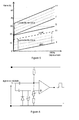
- the majority of the accelerator pedals fitted to vehicles automobiles has an effortlcourse characteristic illustrated in FIG. 1, with for orders of magnitude a return force of 20N when the pedal is in high position and from 30 to 40N in low position.
- Figure 2 illustrates the general appearance of a known relationship (Stevens' law) between the pedal effort and the feeling perceived by the driver. This law shows in the first part of the curve a great sensitivity of the conductor to changes in restoring force, then a saturation of perception and a unacceptable effort for the accelerator function.
- the actuator system which controls the restoring force of a haptic pedal must therefore be able to generate a force of sufficient intensity to be effective from the origin of the displacement of the pedal (in the high position) and at any point of the stroke, without however the overall restoring force applied to the foot of the driver reaches the acceptability limit when the pedal is depressed.
- this condition also meets the willingness to give the driver freedom to consciously override the force of recall, without the additional effort requiring to modify the position natural of the foot on the pedal.
- Force control means used in other fields, engines torque or slave cylinders, are not suitable for equipping a pedal accelerator, for reasons of mass, energy, cost and behaviour. In particular, they may question the security of the function.
- FIG. 3 similar to those of the said patents, illustrates this operation in which the passage of the initial characteristic (A), to characteristic (C) with additional restoring force, done with a strong increase in slope. It results in an abnormal hardening of the pedal at the end of the stroke and poor ergonomics of the haptic principle, to which the restoring force felt by the driver must be at all points of the stroke clearly representative of the variable of adjustment and not of the position of the pedal.
- Patent EP0617674 proposes an efficient solution, with a device additional specific whose action allows to control the restoring force without influence the slope of the initial characteristic of the pedal.
- the device of patent may however be excessively bulky for the implantation of some pedals.
- an actuator for adjustment controlled by an electronic unit can move proportionally to an order quantity the anchor point of one or more springs of pedal recall, the said spring (s) competing continuously and without discontinuity at the initial characteristic of the pedal over the entire stroke of that this.
- the control quantity is a signal from the application software.
- the characteristic (D) can be in itself the sum of several springs in parallel not most often represented, in order to meet the standards for operating safety of the pedals. If a control actuator increases the tension of at least one of the springs and in particular that of the adjusting spring in moving the anchor point away from its initial position, the force characteristic (E) additional zero, will move parallel to characteristic E1, from maximum additional force, so that the characteristic (F) will also move of equal value at any point in the race towards characteristic F1.
- the system therefore behaves like a system with constant force addition, with a parallel translation of the pedal characteristic from (F) to (F1) without increasing the initial slope, from an additional zero force up to a maximum additional force for which the adjusting spring will have been sized.
- the adjusting spring may have a initial prestressing without consequence on the results. It is therefore possible to design according to these principles a pedal that meets the regulations relating to the operational safety of the pedals, comprising only two springs, one of which is an adjustment spring.
- the nature of the springs is without influence on the application of these principles and they can be of any known type, for example spiral or helical couple springs, tension springs or compression, just as the different springs can be different.
- the adjustment spring (s) do not have of action or only a limited action on the hysteresis device which equips usually the pedals.
- the actuator which moves the anchor point of the adjusting springs can be a motor or a gear motor whose movement output is slaved in position by known means, under the control of a electronic unit which receives the commands determined by the specific software to the application.
- the additional restoring force can be canceled quickly by based on criteria predetermined by the application software or the control, such as detection of a declutching action by the driver, the activation of a flashing light, a desire for rapid or persistent acceleration on the part of the driver, according to non-limiting choices programmed in the application.
- the will to accelerate is detected by applying the signal position of the pedal to a bypass function followed by a threshold function, in such a way that the quick cancel command of the restoring force only be validated if the pedal has had a stroke simultaneously and sufficient travel speed.
- These functions can be performed by the electronic actuator control unit or more generally at the level application software.
- the rapid return is obtained by controlling the actuator at full speed. adjustment to the position of zero additional force. It can also result from the action of a controlled decoupling system inserted between the adjustment and the anchor point of the spring so that the anchor point returns by itself to the rest position under the effect of the spring. This solution reduces the nominal speed and therefore the power of the actuator adjustment and it can also be used for certain inhibition of the system by failure.
- FIG (7) gives a schematic representation of the accelerator pedal in the form of a linear assembly of function blocks. The details of construction are known to those skilled in the art and they are not shown for clarity of representation.
- the pedal includes a pedal arm accelerator (1), position feedback sensor (2), hysteresis device (3), return springs (4,5) comprising the adjusting spring (4), a motor or adjustment gear motor (6), controlled by an electronic unit (7).
- the return spring (5) can be formed of one or two springs, the reaction forces of which act on the hysteresis device (3).
- the position sensor, hysteresis device, return spring (s) are in accordance with solutions known per se for the construction of this type of pedal. It goes without saying that the position sensor could be separated from the mechanism pedal without the principles being challenged.
- the return spring (4) used as adjustment spring is a torque spring, helical or spiral.
- This kind of spring favors a reduced bulk and it allows an active stroke more long that meets the needs of the setting.
- this is only a preferred example and a construction variant could use a spring adjustment (4) of traction or compression type, according to the principles of the invention exposed above.
- this spring does not exercise action on the hysteresis device (3).
- One end of the spring (4) is integral movements of the pedal and the other end is fixed to the movement of output of the adjustment gearmotor (6).
- the adjustment motor or gearmotor (6) is preferably not reversible mechanically so that the position of setting is maintained without energy consumption.
- Figure 7 shows a worm-type gearmotor (6) which is among other solutions appropriate.
- the end of the spring (4) could also be actuated by a screw nut device tangent to the spring.
- a realization according to the provision of the Figure 7 requires that the pedal axis can rotate freely in the center of the concentric reducer. This representation should only be seen as example of realization.
- the reducer could be of a different nature and / or the axis pedal could just as easily be pulled out on the side opposite the assembly.
- Figure (8) shows a construction variant in which the motor or geared motor (6) is distant from the pedal to which a device for link transmits the adjustment movement.
- a sensor transmits to the electronic control unit the signal (8) from the position of the spring anchor point (4).
- the position signal can also result from the measurement of the displacement of an intermediate mechanical element, the direct control of a stepper motor or any other known system.
- a controlled uncoupling device for example of the billing type, dog clutch, clutch, or any other known device which makes it possible to release instantly the anchor point of the adjusting spring (4) so that it return by itself to its initial position by the application of a signal ordered.
- Detection of the driver's desire to accelerate is achieved by applying the signal from the pedal position feedback to a detection function whose principle is illustrated by FIG. 7 in the form of an electronic diagram of analog technology.
- the pedal position feedback signal is applied to an RC tap-off circuit which delivers a signal representative of both the amplitude and speed of movement of the pedal.
- This signal is applied to a threshold comparator, the output of which provides a control signal only if the amplitude and speed of movement of the pedal are sufficient.
- a sudden movement of the pedal instantly controls a rapid return to zero force provided the stroke is sufficient, typically a few millimeters.
- the return can also be ordered by a slower movement of the pedal, above a minimum action speed, provided that displacement be insistent.
- the trigger delay then depends on the speed driving.
- the gearmotor has a reduction ratio particularly high and slow speed of the output movement, which authorizes the use of a very low power motor.
- This variant of realization of reduced cost finds a particular application in the realization an accelerator pedal intended to improve driving comfort by electric adjustment of a personalized restoring force.
- This invention finds a privileged use as a Human Interface Machine in driving assistance applications such as speed limiters, assistance in respecting safety distances between vehicles, anti-collision alert, and in general assistance aimed at improving the comfort and safety of the conduct. It can help reduce consumption as well as support for driver decisions in following a road map electronic.
Abstract
Description
Claims (10)
- Pédale d'accélérateur à contrôle de force de rappel intégré, comprenant un bras de pédale (1), un capteur de recopie de position (2), un dispositif d'hystérésis (3), des ressorts de rappel (4,5) caractérisée en ce qu'un actionneur de réglage (6) commandé par une unité électronique (7) peut déplacer proportionnellement à une grandeur de commande issue d'un logiciel d'application le point d'ancrage d'au moins un des ressorts de rappel (4,5) utilisé en ressort de réglage, le dit ressort concourant en permanence et sans discontinuité à la caractéristique initiale de la pédale sur toute la course de celle ci.
- Pédale d'accélérateur à contrôle de force de rappel intégré selon la revendication 1, caractérisée en ce que à chaque position du point d'ancrage du ou des ressorts de réglage correspond une force et un couple de rappel additionnels constants en tout point de la course, déterminant une translation de la caractéristique de pédale parallèle à la caractéristique d'origine entre une position de force additionnelle nulle et une position de force additionnelle maximum.
- Pédale d'accélérateur à contrôle de force de rappel intégré selon les revendications 1et 2, caractérisée en ce que le ou les ressorts de réglage (4) n'ont pas d'action sur le dispositif d'hystérésis de la pédale (3) ou seulement une action limitée.
- Pédale d'accélérateur à contrôle de force de rappel intégré selon l'ensemble des revendications précédentes caractérisée en ce que selon un mode de réalisation préférentiel le(s) ressort(s) de réglage (4) est un ressort couple de type spiral ou en hélice et en ce que l'actionneur (6) est un motoréducteur à vis sans fin ou un dispositif vis écrou tangent au ressort.
- Pédale d'accélérateur à contrôle de force de rappel intégré selon l'ensemble des revendications précédentes, caractérisée en ce que le mouvement de l'actionneur (6) est non réversible mécaniquement et en ce qu'il existe entre l'actionneur et le point d'ancrage du ressort de réglage (4) un dispositif de désaccouplement commandé par lequel le point d'ancrage revient en position initiale.
- Pédale d'accélérateur à contrôle de force de rappel intégré selon l'ensemble des revendications précédentes, caractérisée en ce que le moteur ou motoréducteur (6) peut être éloigné de la pédale à laquelle il transmet le mouvement de réglage par un dispositif de liaison.
- Pédale d'accélérateur à contrôle de force de rappel intégré selon l'ensemble des revendications précédentes, caractérisée en ce que l'unité électronique de contrôle (7) ou le logiciel d'application peuvent commander un retour rapide du réglage de la force de rappel en position nulle en fonction de critères prédéfinis comme une action de débrayage par le conducteur, la mise en service d'un clignotant, la détection de la volonté d'accélérer du conducteur.
- Pédale d'accélérateur à contrôle de force de rappel intégré selon l'ensemble des revendications précédentes, caractérisée en ce que le retour rapide peut résulter de la commande à pleine vitesse de l'actionneur (6) ou de la commande du dispositif de désaccouplement commandé.
- Pédale d'accélérateur à contrôle de force de rappel intégré selon l'ensemble des revendications précédentes, caractérisée en ce que la volonté d'accélérer du conducteur est détectée en appliquant le signal de recopie de position de la pédale à une fonction de dérivation suivie d'une fonction de seuil de telle façon que le signal de retour rapide ne soit validé que si la pédale a eu simultanément une course et une vitesse de déplacement suffisantes.
- Pédale d'accélérateur à contrôle de force de rappel intégré selon l'ensemble des revendications précédentes, caractérisée en ce que cette invention trouve un usage privilégié comme Interface Homme Machine, dans des applications d'aide à la conduite tels les limiteurs de vitesse, l'aide au respect des distances de sécurité inter véhicules, l'alerte anti-collision, et en général les assistances visant à améliorer le confort et la sécurité de la conduite. Elle peut participer à la réduction de la consommation ainsi qu'à l'accompagnement des décisions du conducteur dans le suivi d'une carte routière électronique. Cette pédale convient aussi la réalisation économique d'une pédale d'accélérateur permettant le réglage électrique d'une force de rappel personnalisée.
Applications Claiming Priority (2)
| Application Number | Priority Date | Filing Date | Title |
|---|---|---|---|
| FR0207960A FR2841505B1 (fr) | 2002-06-26 | 2002-06-26 | Pedale d'accelerateur a controle de force de rappel integre |
| FR0207960 | 2002-06-26 |
Publications (2)
| Publication Number | Publication Date |
|---|---|
| EP1375233A1 true EP1375233A1 (fr) | 2004-01-02 |
| EP1375233B1 EP1375233B1 (fr) | 2005-10-26 |
Family
ID=29717110
Family Applications (1)
| Application Number | Title | Priority Date | Filing Date |
|---|---|---|---|
| EP20030350003 Expired - Lifetime EP1375233B1 (fr) | 2002-06-26 | 2003-06-23 | Pédale d'accélérateur à contrôle de force de rappel intégré |
Country Status (3)
| Country | Link |
|---|---|
| EP (1) | EP1375233B1 (fr) |
| DE (1) | DE60302011T2 (fr) |
| FR (1) | FR2841505B1 (fr) |
Cited By (11)
| Publication number | Priority date | Publication date | Assignee | Title |
|---|---|---|---|---|
| EP1602520A3 (fr) * | 2004-06-05 | 2006-08-16 | AB Elektronik GmbH | Ensemble d'une pédale pour automobiles |
| US20100083789A1 (en) * | 2008-10-06 | 2010-04-08 | Mikuni Corporation | Accelerator pedal device |
| WO2010130605A1 (fr) * | 2009-05-15 | 2010-11-18 | Conti Temic Microelectronic Gmbh | Système de pédale compact pour un véhicule à moteur |
| WO2010130606A1 (fr) * | 2009-05-15 | 2010-11-18 | Conti Temic Microelectronic Gmbh | Procédé et dispositif de régulation de vitesse |
| EP2613217A1 (fr) * | 2010-08-31 | 2013-07-10 | Honda Motor Co., Ltd. | Dispositif à pédales à force de réaction |
| CN103419632A (zh) * | 2013-08-29 | 2013-12-04 | 清华大学 | 一种主动反馈式汽车油门踏板装置 |
| US20140373668A1 (en) * | 2011-12-27 | 2014-12-25 | Honda Motor Co., Ltd. | Reactive force pedal device |
| CN104632418A (zh) * | 2015-01-15 | 2015-05-20 | 东风朝阳朝柴动力有限公司 | 车用发动机柔性限速装置 |
| US9110490B2 (en) | 2011-08-31 | 2015-08-18 | Ksr Ip Holdings Llc. | Floor mount ETC pedal with integrated kickdown and tactile alert mechanisms |
| US9459649B2 (en) | 2013-03-15 | 2016-10-04 | Cts Corporation | Active force pedal assembly |
| WO2016202335A1 (fr) * | 2015-06-16 | 2016-12-22 | Continental Automotive Gmbh | Pédale d'accélérateur pour la commande d'un moteur d'entraînement d'un véhicule à moteur, présentant une position de point zéro pouvant être déplacée |
Families Citing this family (11)
| Publication number | Priority date | Publication date | Assignee | Title |
|---|---|---|---|---|
| JP5809459B2 (ja) * | 2011-06-27 | 2015-11-11 | 株式会社ミクニ | アクセルペダル装置 |
| DE102015202860A1 (de) | 2015-02-17 | 2016-08-18 | Continental Automotive Gmbh | Fluidaktor für haptisch wahrnehmbares Signal an einem Pedal |
| DE102015204236A1 (de) | 2015-03-10 | 2016-09-15 | Continental Automotive Gmbh | Pedal mit adaptiver Kraftrückkopplung und Schneckenantrieb |
| DE102015204223A1 (de) | 2015-03-10 | 2016-09-15 | Continental Automotive Gmbh | Pedal mit adaptiver Kraftrückkopplung |
| DE102015209189A1 (de) | 2015-05-20 | 2016-11-24 | Continental Automotive Gmbh | Pedal mit einem Aktor zum Erzeugen eines haptisch wahrnehmbaren Signals |
| DE102015209387A1 (de) | 2015-05-22 | 2016-11-24 | Continental Automotive Gmbh | Pedal mit einer Pedalplatte und mit einer Einrichtung zur Erzeugung einer Bewegung zur haptischen Signalgebung |
| DE102015212499A1 (de) | 2015-07-03 | 2017-01-05 | Continental Automotive Gmbh | Verfahren zum Betrieb eines Gaspedals mit einem Aktor zur Erzeugung eines haptischen Signals |
| DE102016001369B4 (de) | 2016-02-06 | 2018-03-29 | Audi Ag | Verfahren zur automatischen Benutzeranpassung der Reizcharakteristik eines aktiven Bedienelementes eines Fahrzeugs |
| DE102016225578A1 (de) | 2016-12-20 | 2018-06-21 | Continental Automotive Gmbh | Fahrpedaleinheit mit passiver Pedaleinheit und Aktor |
| DE102017200662A1 (de) | 2017-01-17 | 2018-07-19 | Continental Automotive Gmbh | Fluidaktor für haptisch wahrnehmbares Signal an einem Gaspedal |
| DE102017200661A1 (de) | 2017-01-17 | 2018-07-19 | Continental Automotive Gmbh | Fluidaktor für haptisch wahrnehmbares Signal an einem Gaspedal |
Citations (5)
| Publication number | Priority date | Publication date | Assignee | Title |
|---|---|---|---|---|
| DE2723562A1 (de) | 1977-05-25 | 1978-11-30 | Lickert Herbert Dipl Wirtsch I | Gaspedaldrucksteuerung |
| EP0617674A1 (fr) | 1991-12-26 | 1994-10-05 | Alain Landrretche | Dispositif d'assistance au controle de la puissance des vehicules equipes d'un moteur. |
| DE19620929A1 (de) | 1996-05-24 | 1997-11-27 | Porsche Ag | Längsregelsystem für Kraftfahrzeuge mit haptischem Gaspedal |
| EP0962350A2 (fr) | 1998-06-05 | 1999-12-08 | Bayerische Motoren Werke Aktiengesellschaft | Appareil pour modifier la caractéristique de déplacement d'un papillon moteur et d'une pédale d'accélérateur |
| WO2000056566A1 (fr) | 1999-03-24 | 2000-09-28 | Nomix Ab | Systeme de reglage de vitesse, unite de commande d'un tel systeme et procede de reglage de la vitesse d'un vehicule |
-
2002
- 2002-06-26 FR FR0207960A patent/FR2841505B1/fr not_active Expired - Fee Related
-
2003
- 2003-06-23 EP EP20030350003 patent/EP1375233B1/fr not_active Expired - Lifetime
- 2003-06-23 DE DE2003602011 patent/DE60302011T2/de not_active Expired - Lifetime
Patent Citations (5)
| Publication number | Priority date | Publication date | Assignee | Title |
|---|---|---|---|---|
| DE2723562A1 (de) | 1977-05-25 | 1978-11-30 | Lickert Herbert Dipl Wirtsch I | Gaspedaldrucksteuerung |
| EP0617674A1 (fr) | 1991-12-26 | 1994-10-05 | Alain Landrretche | Dispositif d'assistance au controle de la puissance des vehicules equipes d'un moteur. |
| DE19620929A1 (de) | 1996-05-24 | 1997-11-27 | Porsche Ag | Längsregelsystem für Kraftfahrzeuge mit haptischem Gaspedal |
| EP0962350A2 (fr) | 1998-06-05 | 1999-12-08 | Bayerische Motoren Werke Aktiengesellschaft | Appareil pour modifier la caractéristique de déplacement d'un papillon moteur et d'une pédale d'accélérateur |
| WO2000056566A1 (fr) | 1999-03-24 | 2000-09-28 | Nomix Ab | Systeme de reglage de vitesse, unite de commande d'un tel systeme et procede de reglage de la vitesse d'un vehicule |
Cited By (20)
| Publication number | Priority date | Publication date | Assignee | Title |
|---|---|---|---|---|
| EP1602520A3 (fr) * | 2004-06-05 | 2006-08-16 | AB Elektronik GmbH | Ensemble d'une pédale pour automobiles |
| US7631574B2 (en) | 2004-06-05 | 2009-12-15 | AB Electronic GmbH | Accelerator pedal for a motor vehicle |
| US20100083789A1 (en) * | 2008-10-06 | 2010-04-08 | Mikuni Corporation | Accelerator pedal device |
| CN101712280A (zh) * | 2008-10-06 | 2010-05-26 | 株式会社三国 | 加速踏板装置 |
| US9079492B2 (en) * | 2008-10-06 | 2015-07-14 | Mikuni Corporation | Accelerator pedal device |
| CN101712280B (zh) * | 2008-10-06 | 2015-07-08 | 株式会社三国 | 加速踏板装置 |
| WO2010130605A1 (fr) * | 2009-05-15 | 2010-11-18 | Conti Temic Microelectronic Gmbh | Système de pédale compact pour un véhicule à moteur |
| WO2010130606A1 (fr) * | 2009-05-15 | 2010-11-18 | Conti Temic Microelectronic Gmbh | Procédé et dispositif de régulation de vitesse |
| EP2613217A1 (fr) * | 2010-08-31 | 2013-07-10 | Honda Motor Co., Ltd. | Dispositif à pédales à force de réaction |
| US8770060B2 (en) | 2010-08-31 | 2014-07-08 | Honda Motor Co., Ltd. | Reaction force pedal device |
| EP2613217A4 (fr) * | 2010-08-31 | 2014-05-07 | Honda Motor Co Ltd | Dispositif à pédales à force de réaction |
| US9933808B2 (en) | 2010-08-31 | 2018-04-03 | Honda Motor Co., Ltd. | Reaction force pedal device |
| US9110490B2 (en) | 2011-08-31 | 2015-08-18 | Ksr Ip Holdings Llc. | Floor mount ETC pedal with integrated kickdown and tactile alert mechanisms |
| US20140373668A1 (en) * | 2011-12-27 | 2014-12-25 | Honda Motor Co., Ltd. | Reactive force pedal device |
| US9229469B2 (en) * | 2011-12-27 | 2016-01-05 | Honda Motor Co., Ltd. | Reactive force pedal device |
| US9459649B2 (en) | 2013-03-15 | 2016-10-04 | Cts Corporation | Active force pedal assembly |
| CN103419632B (zh) * | 2013-08-29 | 2015-08-19 | 清华大学 | 一种主动反馈式汽车油门踏板装置 |
| CN103419632A (zh) * | 2013-08-29 | 2013-12-04 | 清华大学 | 一种主动反馈式汽车油门踏板装置 |
| CN104632418A (zh) * | 2015-01-15 | 2015-05-20 | 东风朝阳朝柴动力有限公司 | 车用发动机柔性限速装置 |
| WO2016202335A1 (fr) * | 2015-06-16 | 2016-12-22 | Continental Automotive Gmbh | Pédale d'accélérateur pour la commande d'un moteur d'entraînement d'un véhicule à moteur, présentant une position de point zéro pouvant être déplacée |
Also Published As
| Publication number | Publication date |
|---|---|
| FR2841505A1 (fr) | 2004-01-02 |
| EP1375233B1 (fr) | 2005-10-26 |
| DE60302011T2 (de) | 2006-07-13 |
| DE60302011D1 (de) | 2005-12-01 |
| FR2841505B1 (fr) | 2004-08-27 |
Similar Documents
| Publication | Publication Date | Title |
|---|---|---|
| EP1375233B1 (fr) | Pédale d'accélérateur à contrôle de force de rappel intégré | |
| EP3350012B1 (fr) | Sélecteur d'une boite de vitesse automatique de véhicule automobile et procédé de sélection du mode de conduite autonome | |
| WO2015033034A1 (fr) | Interface de commande à retour haptique | |
| EP3145783B1 (fr) | Procédé de contrôle d'un groupe motopropulseur d'un véhicule, dispositif et véhicule correspondant | |
| EP3350014B1 (fr) | Sélecteur de commande d'un véhicule automobile et procédé de sélection d'une commande de véhicule automobile | |
| FR3007366A1 (fr) | Dispositif d'actionnement de freins | |
| EP3671393A1 (fr) | Dispositif de commande de la motorisation d'un train d'atterrissage | |
| FR2678884A1 (fr) | Actionneur rotatif apte a engendrer sur le volant de manóoeuvre d'un systeme de commande, un couple resistant variable selon une loi adaptative. | |
| EP2139715B1 (fr) | Dispositif de commande du mode de fonctionnement electrique d'un groupe motopropulseur hybride de vehicule automobile, par action sur la pedale d'accelerateur | |
| EP1547891A1 (fr) | Commande de freinage d'un véhicule électrique avec récupération d'énergie | |
| FR2871424A1 (fr) | Frein de stationnement pour vehicule a demultiplicateur de l 'effort | |
| EP1534567B1 (fr) | Dispositif de commande de l'acceleration et du freinage pour vehicule | |
| FR2908101A1 (fr) | Dispositif restituteur de force dans un vehicule mecaniquement decouple en direction | |
| EP1491384B1 (fr) | Système de génération de force de rappel variable pour pédale d'accélérateur | |
| FR2995280A1 (fr) | Commandes pour roulage electrique pour avion | |
| FR2855465A1 (fr) | Systeme de generation de force de rappel variable pour pedale d'accelerateur | |
| EP4267420A1 (fr) | Dispositif d'accélération d'un véhicule | |
| FR2968609A1 (fr) | Dispositif generateur de valeur de pedale de vehicule automobile | |
| FR2728835A1 (fr) | Systeme de commande de croisiere d'un vehicule automobile | |
| EP3478547B1 (fr) | Dispositif de controle d'un frein de stationnement de vehicule automobile | |
| WO2004067342A1 (fr) | Dispositif et procede de commande de freinage au cours des phases d’arret et de mises en mouvement d’un vehicule automobile equipe d’un freinage decouple | |
| EP0657322A1 (fr) | Procédé de commande pour véhicule automobile à propulsion électrique et dispositif pour sa mise en oeuvre | |
| FR2877304A1 (fr) | Systeme de direction du type sans colonne pour un vehicule automobile | |
| FR2533512A1 (fr) | Dispositif d'assistance a la conduite economique pour vehicule automobile | |
| FR2853596A1 (fr) | Vehicule automobile comportant un dispositif de regulation de vitesse et procede de commande associe |
Legal Events
| Date | Code | Title | Description |
|---|---|---|---|
| PUAI | Public reference made under article 153(3) epc to a published international application that has entered the european phase |
Free format text: ORIGINAL CODE: 0009012 |
|
| AK | Designated contracting states |
Kind code of ref document: A1 Designated state(s): AT BE BG CH CY CZ DE DK EE ES FI FR GB GR HU IE IT LI LU MC NL PT RO SE SI SK TR |
|
| AX | Request for extension of the european patent |
Extension state: AL LT LV MK |
|
| 17P | Request for examination filed |
Effective date: 20040616 |
|
| AKX | Designation fees paid |
Designated state(s): DE FR GB |
|
| GRAP | Despatch of communication of intention to grant a patent |
Free format text: ORIGINAL CODE: EPIDOSNIGR1 |
|
| GRAS | Grant fee paid |
Free format text: ORIGINAL CODE: EPIDOSNIGR3 |
|
| GRAA | (expected) grant |
Free format text: ORIGINAL CODE: 0009210 |
|
| AK | Designated contracting states |
Kind code of ref document: B1 Designated state(s): DE FR GB |
|
| PG25 | Lapsed in a contracting state [announced via postgrant information from national office to epo] |
Ref country code: GB Free format text: LAPSE BECAUSE OF FAILURE TO SUBMIT A TRANSLATION OF THE DESCRIPTION OR TO PAY THE FEE WITHIN THE PRESCRIBED TIME-LIMIT Effective date: 20051026 |
|
| REG | Reference to a national code |
Ref country code: GB Ref legal event code: FG4D Free format text: NOT ENGLISH |
|
| REF | Corresponds to: |
Ref document number: 60302011 Country of ref document: DE Date of ref document: 20051201 Kind code of ref document: P |
|
| GBV | Gb: ep patent (uk) treated as always having been void in accordance with gb section 77(7)/1977 [no translation filed] |
Effective date: 20051026 |
|
| PLBE | No opposition filed within time limit |
Free format text: ORIGINAL CODE: 0009261 |
|
| STAA | Information on the status of an ep patent application or granted ep patent |
Free format text: STATUS: NO OPPOSITION FILED WITHIN TIME LIMIT |
|
| 26N | No opposition filed |
Effective date: 20060727 |
|
| REG | Reference to a national code |
Ref country code: DE Ref legal event code: R082 Ref document number: 60302011 Country of ref document: DE |
|
| REG | Reference to a national code |
Ref country code: DE Ref legal event code: R081 Ref document number: 60302011 Country of ref document: DE Owner name: CONTI TEMIC MICROELECTRONIC GMBH, DE Free format text: FORMER OWNER: LANDERRETCHE, ALAIN, NANTES, FR Effective date: 20120416 |
|
| REG | Reference to a national code |
Ref country code: FR Ref legal event code: TP Owner name: CONTI TEMIC MICROELECTRONIC GMBH, DE Effective date: 20120730 |
|
| REG | Reference to a national code |
Ref country code: FR Ref legal event code: PLFP Year of fee payment: 14 |
|
| REG | Reference to a national code |
Ref country code: FR Ref legal event code: PLFP Year of fee payment: 15 |
|
| REG | Reference to a national code |
Ref country code: FR Ref legal event code: PLFP Year of fee payment: 16 |
|
| PGFP | Annual fee paid to national office [announced via postgrant information from national office to epo] |
Ref country code: DE Payment date: 20180630 Year of fee payment: 16 |
|
| PGFP | Annual fee paid to national office [announced via postgrant information from national office to epo] |
Ref country code: FR Payment date: 20180620 Year of fee payment: 16 |
|
| REG | Reference to a national code |
Ref country code: DE Ref legal event code: R119 Ref document number: 60302011 Country of ref document: DE |
|
| PG25 | Lapsed in a contracting state [announced via postgrant information from national office to epo] |
Ref country code: DE Free format text: LAPSE BECAUSE OF NON-PAYMENT OF DUE FEES Effective date: 20200101 |
|
| PG25 | Lapsed in a contracting state [announced via postgrant information from national office to epo] |
Ref country code: FR Free format text: LAPSE BECAUSE OF NON-PAYMENT OF DUE FEES Effective date: 20190630 |