EP1375032A1 - Kupfer-Giessform für das Strangiessen von Metallschmelzen - Google Patents
Kupfer-Giessform für das Strangiessen von Metallschmelzen Download PDFInfo
- Publication number
- EP1375032A1 EP1375032A1 EP03013616A EP03013616A EP1375032A1 EP 1375032 A1 EP1375032 A1 EP 1375032A1 EP 03013616 A EP03013616 A EP 03013616A EP 03013616 A EP03013616 A EP 03013616A EP 1375032 A1 EP1375032 A1 EP 1375032A1
- Authority
- EP
- European Patent Office
- Prior art keywords
- diffusion barrier
- barrier layer
- layer
- copper
- mold
- Prior art date
- Legal status (The legal status is an assumption and is not a legal conclusion. Google has not performed a legal analysis and makes no representation as to the accuracy of the status listed.)
- Withdrawn
Links
- RYGMFSIKBFXOCR-UHFFFAOYSA-N Copper Chemical compound [Cu] RYGMFSIKBFXOCR-UHFFFAOYSA-N 0.000 title claims abstract description 32
- 229910052802 copper Inorganic materials 0.000 title claims abstract description 32
- 239000010949 copper Substances 0.000 title claims abstract description 32
- 238000009749 continuous casting Methods 0.000 title claims abstract description 6
- 229910052751 metal Inorganic materials 0.000 title description 2
- 239000002184 metal Substances 0.000 title description 2
- 150000002739 metals Chemical class 0.000 title description 2
- 238000009792 diffusion process Methods 0.000 claims abstract description 50
- 230000004888 barrier function Effects 0.000 claims abstract description 47
- 239000000463 material Substances 0.000 claims abstract description 22
- 238000005266 casting Methods 0.000 claims abstract description 18
- NINIDFKCEFEMDL-UHFFFAOYSA-N Sulfur Chemical compound [S] NINIDFKCEFEMDL-UHFFFAOYSA-N 0.000 claims abstract description 13
- 239000011593 sulfur Substances 0.000 claims abstract description 13
- 229910052717 sulfur Inorganic materials 0.000 claims abstract description 13
- HCHKCACWOHOZIP-UHFFFAOYSA-N Zinc Chemical compound [Zn] HCHKCACWOHOZIP-UHFFFAOYSA-N 0.000 claims abstract description 12
- 229910052725 zinc Inorganic materials 0.000 claims abstract description 12
- 239000011701 zinc Substances 0.000 claims abstract description 12
- 239000000161 steel melt Substances 0.000 claims abstract description 6
- 229910052752 metalloid Inorganic materials 0.000 claims abstract description 4
- 150000002738 metalloids Chemical class 0.000 claims abstract description 4
- 229910000831 Steel Inorganic materials 0.000 claims description 6
- 239000010959 steel Substances 0.000 claims description 6
- 239000003973 paint Substances 0.000 claims description 3
- 239000004033 plastic Substances 0.000 claims description 3
- 229920003023 plastic Polymers 0.000 claims description 3
- 239000011347 resin Substances 0.000 claims description 3
- 229920005989 resin Polymers 0.000 claims description 3
- 229910010293 ceramic material Inorganic materials 0.000 claims description 2
- 239000010410 layer Substances 0.000 abstract description 61
- 239000002356 single layer Substances 0.000 abstract description 6
- VYZAMTAEIAYCRO-UHFFFAOYSA-N Chromium Chemical compound [Cr] VYZAMTAEIAYCRO-UHFFFAOYSA-N 0.000 description 14
- PXHVJJICTQNCMI-UHFFFAOYSA-N Nickel Chemical compound [Ni] PXHVJJICTQNCMI-UHFFFAOYSA-N 0.000 description 6
- 229910018072 Al 2 O 3 Inorganic materials 0.000 description 5
- 239000011651 chromium Substances 0.000 description 5
- 239000011248 coating agent Substances 0.000 description 4
- 238000000576 coating method Methods 0.000 description 4
- PMHQVHHXPFUNSP-UHFFFAOYSA-M copper(1+);methylsulfanylmethane;bromide Chemical compound Br[Cu].CSC PMHQVHHXPFUNSP-UHFFFAOYSA-M 0.000 description 4
- 230000007797 corrosion Effects 0.000 description 4
- 238000005260 corrosion Methods 0.000 description 4
- TWNQGVIAIRXVLR-UHFFFAOYSA-N oxo(oxoalumanyloxy)alumane Chemical compound O=[Al]O[Al]=O TWNQGVIAIRXVLR-UHFFFAOYSA-N 0.000 description 4
- 239000011241 protective layer Substances 0.000 description 4
- 239000010936 titanium Substances 0.000 description 4
- 229910001369 Brass Inorganic materials 0.000 description 3
- RTAQQCXQSZGOHL-UHFFFAOYSA-N Titanium Chemical compound [Ti] RTAQQCXQSZGOHL-UHFFFAOYSA-N 0.000 description 3
- 230000015572 biosynthetic process Effects 0.000 description 3
- 239000010951 brass Substances 0.000 description 3
- 229910052804 chromium Inorganic materials 0.000 description 3
- 238000010586 diagram Methods 0.000 description 3
- 229910052759 nickel Inorganic materials 0.000 description 3
- BNGXYYYYKUGPPF-UHFFFAOYSA-M (3-methylphenyl)methyl-triphenylphosphanium;chloride Chemical compound [Cl-].CC1=CC=CC(C[P+](C=2C=CC=CC=2)(C=2C=CC=CC=2)C=2C=CC=CC=2)=C1 BNGXYYYYKUGPPF-UHFFFAOYSA-M 0.000 description 2
- NRTOMJZYCJJWKI-UHFFFAOYSA-N Titanium nitride Chemical compound [Ti]#N NRTOMJZYCJJWKI-UHFFFAOYSA-N 0.000 description 2
- WGLPBDUCMAPZCE-UHFFFAOYSA-N Trioxochromium Chemical group O=[Cr](=O)=O WGLPBDUCMAPZCE-UHFFFAOYSA-N 0.000 description 2
- 229910052782 aluminium Inorganic materials 0.000 description 2
- CXOWYMLTGOFURZ-UHFFFAOYSA-N azanylidynechromium Chemical compound [Cr]#N CXOWYMLTGOFURZ-UHFFFAOYSA-N 0.000 description 2
- 238000005229 chemical vapour deposition Methods 0.000 description 2
- 229910000423 chromium oxide Inorganic materials 0.000 description 2
- 238000007598 dipping method Methods 0.000 description 2
- 150000001247 metal acetylides Chemical class 0.000 description 2
- 239000010955 niobium Substances 0.000 description 2
- 150000004767 nitrides Chemical class 0.000 description 2
- 238000005240 physical vapour deposition Methods 0.000 description 2
- 239000011148 porous material Substances 0.000 description 2
- 239000010948 rhodium Substances 0.000 description 2
- 239000002344 surface layer Substances 0.000 description 2
- 229910052719 titanium Inorganic materials 0.000 description 2
- MTPVUVINMAGMJL-UHFFFAOYSA-N trimethyl(1,1,2,2,2-pentafluoroethyl)silane Chemical compound C[Si](C)(C)C(F)(F)C(F)(F)F MTPVUVINMAGMJL-UHFFFAOYSA-N 0.000 description 2
- ZOXJGFHDIHLPTG-UHFFFAOYSA-N Boron Chemical compound [B] ZOXJGFHDIHLPTG-UHFFFAOYSA-N 0.000 description 1
- 239000004593 Epoxy Substances 0.000 description 1
- KJTLSVCANCCWHF-UHFFFAOYSA-N Ruthenium Chemical compound [Ru] KJTLSVCANCCWHF-UHFFFAOYSA-N 0.000 description 1
- XUIMIQQOPSSXEZ-UHFFFAOYSA-N Silicon Chemical compound [Si] XUIMIQQOPSSXEZ-UHFFFAOYSA-N 0.000 description 1
- CYKMNKXPYXUVPR-UHFFFAOYSA-N [C].[Ti] Chemical compound [C].[Ti] CYKMNKXPYXUVPR-UHFFFAOYSA-N 0.000 description 1
- WJPZDRIJJYYRAH-UHFFFAOYSA-N [Zn].[Mo] Chemical compound [Zn].[Mo] WJPZDRIJJYYRAH-UHFFFAOYSA-N 0.000 description 1
- 230000032683 aging Effects 0.000 description 1
- UQZIWOQVLUASCR-UHFFFAOYSA-N alumane;titanium Chemical compound [AlH3].[Ti] UQZIWOQVLUASCR-UHFFFAOYSA-N 0.000 description 1
- XAGFODPZIPBFFR-UHFFFAOYSA-N aluminium Chemical compound [Al] XAGFODPZIPBFFR-UHFFFAOYSA-N 0.000 description 1
- -1 aluminum compound Chemical class 0.000 description 1
- 238000000137 annealing Methods 0.000 description 1
- 229910052796 boron Inorganic materials 0.000 description 1
- 238000001816 cooling Methods 0.000 description 1
- BWFPGXWASODCHM-UHFFFAOYSA-N copper monosulfide Chemical class [Cu]=S BWFPGXWASODCHM-UHFFFAOYSA-N 0.000 description 1
- 238000005336 cracking Methods 0.000 description 1
- 238000000354 decomposition reaction Methods 0.000 description 1
- 230000000694 effects Effects 0.000 description 1
- 230000002349 favourable effect Effects 0.000 description 1
- 230000008595 infiltration Effects 0.000 description 1
- 238000001764 infiltration Methods 0.000 description 1
- 238000002844 melting Methods 0.000 description 1
- 230000008018 melting Effects 0.000 description 1
- 239000007769 metal material Substances 0.000 description 1
- 238000000034 method Methods 0.000 description 1
- FXNGWBDIVIGISM-UHFFFAOYSA-N methylidynechromium Chemical compound [Cr]#[C] FXNGWBDIVIGISM-UHFFFAOYSA-N 0.000 description 1
- 229910052758 niobium Inorganic materials 0.000 description 1
- GUCVJGMIXFAOAE-UHFFFAOYSA-N niobium atom Chemical compound [Nb] GUCVJGMIXFAOAE-UHFFFAOYSA-N 0.000 description 1
- 230000010355 oscillation Effects 0.000 description 1
- 230000001590 oxidative effect Effects 0.000 description 1
- 229920001296 polysiloxane Polymers 0.000 description 1
- 230000001681 protective effect Effects 0.000 description 1
- 229910052702 rhenium Inorganic materials 0.000 description 1
- WUAPFZMCVAUBPE-UHFFFAOYSA-N rhenium atom Chemical compound [Re] WUAPFZMCVAUBPE-UHFFFAOYSA-N 0.000 description 1
- 229910052703 rhodium Inorganic materials 0.000 description 1
- MHOVAHRLVXNVSD-UHFFFAOYSA-N rhodium atom Chemical compound [Rh] MHOVAHRLVXNVSD-UHFFFAOYSA-N 0.000 description 1
- 229910052707 ruthenium Inorganic materials 0.000 description 1
- 239000012266 salt solution Substances 0.000 description 1
- 229910052710 silicon Inorganic materials 0.000 description 1
- 239000010703 silicon Substances 0.000 description 1
- 239000000243 solution Substances 0.000 description 1
- 238000005507 spraying Methods 0.000 description 1
- 239000000126 substance Substances 0.000 description 1
- 229910052715 tantalum Inorganic materials 0.000 description 1
- GUVRBAGPIYLISA-UHFFFAOYSA-N tantalum atom Chemical compound [Ta] GUVRBAGPIYLISA-UHFFFAOYSA-N 0.000 description 1
- 229910052714 tellurium Inorganic materials 0.000 description 1
- PORWMNRCUJJQNO-UHFFFAOYSA-N tellurium atom Chemical compound [Te] PORWMNRCUJJQNO-UHFFFAOYSA-N 0.000 description 1
- 230000007704 transition Effects 0.000 description 1
- WFKWXMTUELFFGS-UHFFFAOYSA-N tungsten Chemical compound [W] WFKWXMTUELFFGS-UHFFFAOYSA-N 0.000 description 1
- 229910052721 tungsten Inorganic materials 0.000 description 1
- 239000010937 tungsten Substances 0.000 description 1
Images

Classifications
-
- B—PERFORMING OPERATIONS; TRANSPORTING
- B22—CASTING; POWDER METALLURGY
- B22D—CASTING OF METALS; CASTING OF OTHER SUBSTANCES BY THE SAME PROCESSES OR DEVICES
- B22D11/00—Continuous casting of metals, i.e. casting in indefinite lengths
- B22D11/04—Continuous casting of metals, i.e. casting in indefinite lengths into open-ended moulds
- B22D11/059—Mould materials or platings
-
- E—FIXED CONSTRUCTIONS
- E02—HYDRAULIC ENGINEERING; FOUNDATIONS; SOIL SHIFTING
- E02F—DREDGING; SOIL-SHIFTING
- E02F3/00—Dredgers; Soil-shifting machines
- E02F3/04—Dredgers; Soil-shifting machines mechanically-driven
- E02F3/88—Dredgers; Soil-shifting machines mechanically-driven with arrangements acting by a sucking or forcing effect, e.g. suction dredgers
- E02F3/8833—Floating installations
-
- E—FIXED CONSTRUCTIONS
- E02—HYDRAULIC ENGINEERING; FOUNDATIONS; SOIL SHIFTING
- E02F—DREDGING; SOIL-SHIFTING
- E02F3/00—Dredgers; Soil-shifting machines
- E02F3/04—Dredgers; Soil-shifting machines mechanically-driven
- E02F3/88—Dredgers; Soil-shifting machines mechanically-driven with arrangements acting by a sucking or forcing effect, e.g. suction dredgers
- E02F3/90—Component parts, e.g. arrangement or adaptation of pumps
- E02F3/907—Measuring or control devices, e.g. control units, detection means or sensors
-
- E—FIXED CONSTRUCTIONS
- E02—HYDRAULIC ENGINEERING; FOUNDATIONS; SOIL SHIFTING
- E02F—DREDGING; SOIL-SHIFTING
- E02F3/00—Dredgers; Soil-shifting machines
- E02F3/04—Dredgers; Soil-shifting machines mechanically-driven
- E02F3/88—Dredgers; Soil-shifting machines mechanically-driven with arrangements acting by a sucking or forcing effect, e.g. suction dredgers
- E02F3/90—Component parts, e.g. arrangement or adaptation of pumps
- E02F3/92—Digging elements, e.g. suction heads
- E02F3/9293—Component parts of suction heads, e.g. edges, strainers for preventing the entry of stones or the like
-
- E—FIXED CONSTRUCTIONS
- E02—HYDRAULIC ENGINEERING; FOUNDATIONS; SOIL SHIFTING
- E02F—DREDGING; SOIL-SHIFTING
- E02F9/00—Component parts of dredgers or soil-shifting machines, not restricted to one of the kinds covered by groups E02F3/00 - E02F7/00
- E02F9/20—Drives; Control devices
- E02F9/2016—Winches
-
- E—FIXED CONSTRUCTIONS
- E02—HYDRAULIC ENGINEERING; FOUNDATIONS; SOIL SHIFTING
- E02F—DREDGING; SOIL-SHIFTING
- E02F9/00—Component parts of dredgers or soil-shifting machines, not restricted to one of the kinds covered by groups E02F3/00 - E02F7/00
- E02F9/26—Indicating devices
- E02F9/261—Surveying the work-site to be treated
Definitions
- the invention relates to a copper mold for the continuous casting of molten steel in the presence of zinc and / or sulfur.
- Zinc as a component e.g. of molten automobile scrap reacts with the hot copper surface and forms in one Diffusion process of brittle ⁇ / ⁇ / ⁇ brass phases. These flake off and run in succession to cracking.
- Sulfur which is present, for example, through casting aids, reacts with copper to large-volume and brittle copper sulfides. These can also flake off. The notch effect resulting from local corrosion is therefore an ideal one Starting point for crack formation.
- the invention is based on the object a copper mold for the continuous casting of molten steel in the presence of zinc and / or sulfur, which have a significantly longer service life has without the heat flow and thus the cooling capacity of the copper mold be influenced in a relevant manner.
- the copper mold is in the most thermally stressed Provide contact area with the molten steel with a diffusion barrier layer.
- Such at least one-layer diffusion barrier layer can according to claim 2 e.g. consist of metals or metalloids, their solubility with zinc and / or sulfur is negligible in the operating temperature range.
- materials include in particular ruthenium (Ru), rhenium (Re), tantalum (Ta), silicon (Si), boron (B), tungsten (W), chromium (Cr) and niobium (Nb). If only zinc Molybdenum (Mo), Titan (Ti), Rhodium (Rh) and Tellurium can also be present (Te) are used.
- the diffusion barrier layer can with the help of a CVD (Chemical Vapor Deposition) or PVD (Physical Vapor Deposition) process directly on a copper surface be applied to a copper mold.
- CVD Chemical Vapor Deposition
- PVD Physical Vapor Deposition
- the diffusion barrier layer on chrome or on other galvanic layers can be applied.
- a diffusion barrier layer can be used as an intermediate layer before application a wear layer, e.g. made of chrome and / or nickel.
- the choice of layer type is determined by two factors. On the one hand, it has to primary objective of a diffusion barrier to be met. On the other hand, the imperative Requirement of good adhesion as an intermediate or top layer.
- chromium oxide As a top layer. Their solubility with zinc and / or with sulfur is in the range of Operating temperatures of a copper mold are negligible.
- the chromium oxide can by a thermal / chemical treatment of a chrome coating, e.g. in a oxidizing atmosphere. This has the advantage that not just the surface itself through an oxide against the diffusion of zinc and / or sulfur in the chrome is protected, but that also the typically existing micro and macro cracks in the chrome coating be closed by the oxide.
- a chrome layer of at least one type of chrome is deposited as a diffusion barrier layer.
- So-called crack-free, micro-cracked and standardized Hard chrome layers can be combined. The combination is carried out in such a way that no cracks are continuous from the layer surface to the base material or become universal in use.
- Layer structure which consists of an intermediate layer of crack-free or micro-cracked Chrome is made and a top layer of standard hard chrome is applied.
- the invention also allows a layer of carbides, nitrides, borides or oxides and their mixed types, for example based on titanium / aluminum (Ti / Al) and chromium (Cr), to be formed as a diffusion barrier layer.
- carbides, nitrides and borides are preferably suitable as intermediate layers.
- Oxides can be used as cover layers.
- the invention sees favorable behavior in particular when using aluminum nitride (AIN), aluminum oxide (Al 2 O 3 ), chromium carbide (CrC), chromium nitride (CrN), titanium carbide (TiC), titanium nitride (TiN), titanium carbon nitride (TiCN), titanium aluminum nitride (TiAIN) and titanium boride (TiB 2 ).
- AIN aluminum nitride
- Al 2 O 3 aluminum oxide
- CrC chromium carbide
- CrN chromium nitride
- TiC titanium carbide
- TiN titanium carbon nitride
- TiCN titanium aluminum nitride
- TiAIN titanium aluminum nitride
- TiB 2 titanium boride
- a diffusion barrier layer can also be formed by applying an aluminum compound, for example aluminum nitrate, to the surface of a copper casting mold, for example a chrome-plated surface. When applied, the surface layer of the casting mold is completely wetted and infiltrated by the salt solution. Annealing at a moderate temperature leads to decomposition to y-aluminum oxide (Al 2 O 3 ) on the entire surface as well as in the micro cracks and open pores. This also prevents the diffusion of zinc and sulfur and thus the formation of brass or sulfur corrosion.
- the aluminum nitrate solution can be applied by dipping, spraying or applying with a brush or roller. The protective effect of the infiltration can be increased by repeated dipping or application.
- Suitable paints, resins or plastics on the surface of a copper mold, e.g. a chrome-plated surface, created a diffusion barrier become.
- Suitable materials are in particular paints, resins or plastics Base of silicone or epoxy.
- the diffusion barrier layer is formed from a ceramic material.
- the Diffusion barrier layer according to claim 5 preferably in the upper half and expediently applied here in the upper quarter or third of the mold length.
- the diffusion barrier layer in a pipe or Plate mold provided in the height area of the bathroom mirror.
- the Diffusion barrier layer applied at a height sufficient to that at oscillation of the bath level, the contact surface is highly stressed overall to cover properly. This range is typically about ⁇ 50 mm or below the bath level or approximately in a range up to approximately 250 mm from the upper edge of the tube or plate mold.
- the area is advantageous between 50 mm and 250 mm, preferably 150 mm to 200 mm from the upper edge away.
- a moving mold (casting roll, casting roll) is according to claim 7 with a diffusion barrier layer, which covers the whole with the Melting steel is in contact with the circumference.
- the diffusion barrier layer according to claim 8 should have a thickness of 0.002 mm to 0.3 mm.
- a preferred thickness of the diffusion barrier layer is according to claim 9 0.005 mm to 0.1 mm is seen.
- a multilayer layer can also be formed. With a multilayer layer several layers and layer materials are combined.
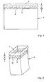
- 1 is a mold plate made of copper.
- the hatched Area 2 illustrates the most thermally stressed Contact area with a molten steel. It has a diffusion barrier layer 3 Mistake.
- the bathroom mirror 4 is indicated in dash-dotted lines.
- the Bathroom mirror 4 can oscillate vertically, so that to cover area 2 Diffusion barrier layer 3 extends about 50 mm above or below the bath level 4. With In other words, the bathroom mirror 4 can also be approximately 150 mm to 200 mm from the top edge 5 of the plate mold 1.
- the diffusion barrier layer 3 consists of a metallic material.
- a tubular mold 6 is indicated in the diagram in FIG.
- Diffusion barrier layer 7 made of a metallic / metalloid. Material illustrates which lies in an area 8 which is approximately 150 mm to 200 mm from the Top 9 of the tubular mold 6 is removed. The height range to the bathroom mirror 10 is about 50 mm.
- FIG. 3 shows in longitudinal section the base material copper 11 of a casting mold 12, such as a plate or tubular mold 1, 6 or a co-rotating mold, not illustrated in more detail, such as a casting roll or casting roll.
- a single-layer diffusion barrier layer 13 made of, for example, aluminum oxide (Al 2 O 3 ) is applied to this base material 11.
- 11 again designates the base material copper of a casting mold 12.
- a multilayer layer 14 is applied to the base material 11, which in the exemplary embodiment consists of a layer 15 of chromium nitride (CrN) brought into contact with the base material 11, a layer 16 of aluminum oxide (Al 2 O 3 ) and a layer 17 as a cover layer made of titanium nitride (TiN ) composed.
- CrN chromium nitride
- Al 2 O 3 aluminum oxide
- TiN titanium nitride
- the base material copper of a casting mold 12 is also 11 designated.
- a single-layer diffusion barrier layer 18 is on the base material 11 made of, for example, aluminum nitride (AIN). It is also a single layer Wear layer 19, for example made of chrome and / or nickel, in Transition area from the base material 11 copper to the diffusion barrier layer 18 provided.
- FIG. 6 again shows the base material 11 copper of a casting mold 12.
- a protective layer 20 made of chromium is applied thereon, which in turn has a diffusion barrier layer 21, for example made of aluminum oxide (Al 2 O 3 ), which runs into the surface of the protective layer 20. is provided.
Landscapes
- Engineering & Computer Science (AREA)
- Mechanical Engineering (AREA)
- Mining & Mineral Resources (AREA)
- Civil Engineering (AREA)
- General Engineering & Computer Science (AREA)
- Structural Engineering (AREA)
- Continuous Casting (AREA)
- Moulds For Moulding Plastics Or The Like (AREA)
- Molds, Cores, And Manufacturing Methods Thereof (AREA)
- Coating With Molten Metal (AREA)
- Other Surface Treatments For Metallic Materials (AREA)
- Mold Materials And Core Materials (AREA)
Applications Claiming Priority (2)
| Application Number | Priority Date | Filing Date | Title |
|---|---|---|---|
| DE10227034 | 2002-06-17 | ||
| DE10227034A DE10227034A1 (de) | 2002-06-17 | 2002-06-17 | Kupfer-Gießform |
Publications (1)
| Publication Number | Publication Date |
|---|---|
| EP1375032A1 true EP1375032A1 (de) | 2004-01-02 |
Family
ID=29594593
Family Applications (1)
| Application Number | Title | Priority Date | Filing Date |
|---|---|---|---|
| EP03013616A Withdrawn EP1375032A1 (de) | 2002-06-17 | 2003-06-16 | Kupfer-Giessform für das Strangiessen von Metallschmelzen |
Country Status (11)
Families Citing this family (10)
| Publication number | Priority date | Publication date | Assignee | Title |
|---|---|---|---|---|
| DE19802809A1 (de) | 1998-01-27 | 1999-07-29 | Km Europa Metal Ag | Flüssigkeitsgekühlte Kokille |
| JP4764199B2 (ja) * | 2005-09-07 | 2011-08-31 | 新日本製鐵株式会社 | 磁性体の粒形状観察装置 |
| WO2008049081A1 (en) * | 2006-10-18 | 2008-04-24 | Inframat Corporation | Casting molds coated for surface enhancement and methods of making them |
| DE102008015096A1 (de) * | 2008-03-19 | 2009-09-24 | Kme Germany Ag & Co. Kg | Verfahren zur Herstellung von Gießformteilen sowie nach dem Verfahren hergestellte Gießformteile |
| US8887532B2 (en) * | 2010-08-24 | 2014-11-18 | Corning Incorporated | Glass-forming tools and methods |
| NO338410B1 (no) * | 2013-01-22 | 2016-08-15 | Norsk Hydro As | En elektrode for aluminiumsfremstilling og en fremgangsmåte for tildannelse av samme |
| KR101469173B1 (ko) * | 2013-02-26 | 2014-12-04 | 조선대학교산학협력단 | 선택적 초합금 적층층을 가진 고내마모성 열간성형 금형 |
| DE102013114326A1 (de) * | 2013-12-18 | 2015-06-18 | Thyssenkrupp Steel Europe Ag | Gießkokille zum Vergießen von Stahlschmelze |
| CN110125350B (zh) * | 2019-06-04 | 2024-08-13 | 中国重型机械研究院股份公司 | 用于板坯连铸机结晶器宽面的多层复合铜板及其制备方法 |
| CN114799063B (zh) * | 2022-04-28 | 2024-03-22 | 河北科技大学 | 碳氮化钛和碳化铬协同增强铁基复合材料叶轮的制备方法 |
Citations (8)
| Publication number | Priority date | Publication date | Assignee | Title |
|---|---|---|---|---|
| US4037646A (en) * | 1975-06-13 | 1977-07-26 | Sumitomo Metal Industries, Ltd. | Molds for continuously casting steel |
| US4197902A (en) * | 1976-07-31 | 1980-04-15 | Kabel-Und Metallwerke Gutehoffnungshuette Ag | Molds for continuous casting of metals |
| JPS59189037A (ja) * | 1983-04-08 | 1984-10-26 | Nippon Kokan Kk <Nkk> | 連続鋳造用鋳型 |
| US5172749A (en) * | 1990-12-24 | 1992-12-22 | Sms Schloemann Siemag Aktiengesellschaft | Continuous steel casting mold |
| JP2000087207A (ja) * | 1998-09-10 | 2000-03-28 | Tocalo Co Ltd | 溶融金属用容器およびその表面処理方法 |
| JP2000218346A (ja) * | 1999-02-01 | 2000-08-08 | Satosen Co Ltd | 鋼の連続鋳造用鋳型およびその製造方法 |
| US6206987B1 (en) * | 1997-12-17 | 2001-03-27 | Km Europa Metal Ag | Method for manufacturing a casting-die body and a casting-die body |
| US6354358B1 (en) * | 1999-11-26 | 2002-03-12 | Nomura Plating Co., Ltd. | Continuous casting mold with tungsten alloy plating and method of producing the same |
Family Cites Families (12)
| Publication number | Priority date | Publication date | Assignee | Title |
|---|---|---|---|---|
| JPS5841933B2 (ja) * | 1977-06-08 | 1983-09-16 | 住友金属工業株式会社 | 鉄鋼用連続鋳造鋳型 |
| JPS5825534B2 (ja) * | 1977-06-10 | 1983-05-27 | 住友金属工業株式会社 | 鉄鋼連続鋳造鋳型 |
| JPS5823822B2 (ja) * | 1977-06-10 | 1983-05-17 | 住友金属工業株式会社 | 鉄鋼用連続鋳造鋳型 |
| JPS5545514A (en) * | 1978-09-22 | 1980-03-31 | Nippon Steel Corp | Mold for continuous casting of iron and steel |
| DE3038289A1 (de) * | 1980-10-10 | 1982-05-27 | Egon 5650 Solingen Evertz | Verfahren zum abscheiden von metallschichten auf den waenden von kokillen |
| DE3218100A1 (de) * | 1982-05-13 | 1983-11-17 | Kabel- und Metallwerke Gutehoffnungshütte AG, 3000 Hannover | Verfahren zur herstellung einer rohrkokille mit rechteckigem bzw. quadratischem querschnitt |
| JPS5973153A (ja) * | 1982-10-21 | 1984-04-25 | Mishima Kosan Co Ltd | 連続鋳造用鋳型及びその製造方法 |
| US5230380A (en) * | 1988-07-22 | 1993-07-27 | Satosen Co., Ltd. | Molds for continuous casting of steel |
| US5014768A (en) * | 1989-06-30 | 1991-05-14 | Waters & Associates | Chill plate having high heat conductivity and wear resistance |
| US5499672A (en) * | 1994-06-01 | 1996-03-19 | Chuetsu Metal Works Co., Ltd. | Mold for continuous casting which comprises a flame sprayed coating layer of a tungsten carbide-based wear-resistant material |
| US6672368B2 (en) * | 2001-02-20 | 2004-01-06 | Alcoa Inc. | Continuous casting of aluminum |
| US7125612B2 (en) * | 2001-02-20 | 2006-10-24 | Alcoa Inc. | Casting of non-ferrous metals |
-
2002
- 2002-06-17 DE DE10227034A patent/DE10227034A1/de not_active Withdrawn
-
2003
- 2003-06-16 RU RU2003117753/02A patent/RU2003117753A/ru not_active Application Discontinuation
- 2003-06-16 EP EP03013616A patent/EP1375032A1/de not_active Withdrawn
- 2003-06-16 TW TW092116246A patent/TWI270422B/zh not_active IP Right Cessation
- 2003-06-17 MX MXPA03005439A patent/MXPA03005439A/es active IP Right Grant
- 2003-06-17 AU AU2003204752A patent/AU2003204752A1/en not_active Abandoned
- 2003-06-17 CN CNA031588956A patent/CN1493415A/zh active Pending
- 2003-06-17 US US10/463,097 patent/US7096922B2/en not_active Expired - Fee Related
- 2003-06-17 KR KR1020030039051A patent/KR20040002598A/ko not_active Withdrawn
- 2003-06-17 JP JP2003171960A patent/JP2004017162A/ja active Pending
- 2003-06-17 BR BR0302145-9A patent/BR0302145A/pt not_active Application Discontinuation
Patent Citations (8)
| Publication number | Priority date | Publication date | Assignee | Title |
|---|---|---|---|---|
| US4037646A (en) * | 1975-06-13 | 1977-07-26 | Sumitomo Metal Industries, Ltd. | Molds for continuously casting steel |
| US4197902A (en) * | 1976-07-31 | 1980-04-15 | Kabel-Und Metallwerke Gutehoffnungshuette Ag | Molds for continuous casting of metals |
| JPS59189037A (ja) * | 1983-04-08 | 1984-10-26 | Nippon Kokan Kk <Nkk> | 連続鋳造用鋳型 |
| US5172749A (en) * | 1990-12-24 | 1992-12-22 | Sms Schloemann Siemag Aktiengesellschaft | Continuous steel casting mold |
| US6206987B1 (en) * | 1997-12-17 | 2001-03-27 | Km Europa Metal Ag | Method for manufacturing a casting-die body and a casting-die body |
| JP2000087207A (ja) * | 1998-09-10 | 2000-03-28 | Tocalo Co Ltd | 溶融金属用容器およびその表面処理方法 |
| JP2000218346A (ja) * | 1999-02-01 | 2000-08-08 | Satosen Co Ltd | 鋼の連続鋳造用鋳型およびその製造方法 |
| US6354358B1 (en) * | 1999-11-26 | 2002-03-12 | Nomura Plating Co., Ltd. | Continuous casting mold with tungsten alloy plating and method of producing the same |
Non-Patent Citations (3)
| Title |
|---|
| PATENT ABSTRACTS OF JAPAN vol. 009, no. 055 (M - 362) 9 March 1985 (1985-03-09) * |
| PATENT ABSTRACTS OF JAPAN vol. 2000, no. 06 22 September 2000 (2000-09-22) * |
| PATENT ABSTRACTS OF JAPAN vol. 2000, no. 11 3 January 2001 (2001-01-03) * |
Also Published As
| Publication number | Publication date |
|---|---|
| BR0302145A (pt) | 2004-09-08 |
| TW200400092A (en) | 2004-01-01 |
| CN1493415A (zh) | 2004-05-05 |
| TWI270422B (en) | 2007-01-11 |
| DE10227034A1 (de) | 2003-12-24 |
| AU2003204752A1 (en) | 2004-01-15 |
| RU2003117753A (ru) | 2005-01-10 |
| KR20040002598A (ko) | 2004-01-07 |
| JP2004017162A (ja) | 2004-01-22 |
| MXPA03005439A (es) | 2005-02-14 |
| US20030230394A1 (en) | 2003-12-18 |
| US7096922B2 (en) | 2006-08-29 |
Similar Documents
| Publication | Publication Date | Title |
|---|---|---|
| EP1888805B1 (de) | Beschichteter Körper, insbesondere Walze, aus kohlefaserverstärktem Kunststoff (CFK) für Papier- und Druckmaschinen und Verfahren zum Herstellen eines solchen Körpers | |
| DE69014161T2 (de) | Werkzeug unter Verwendung von Gold als Bindemittel und Verfahren zu dessen Herstellung. | |
| EP1726687B1 (de) | Beschichtes Werkzeug | |
| EP1375032A1 (de) | Kupfer-Giessform für das Strangiessen von Metallschmelzen | |
| DE2917348B1 (de) | Verbundkoerper und seine Verwendung | |
| EP1953004B1 (de) | Spitzerklinge | |
| DE19825572A1 (de) | Werkzeug aus einem Grundkörper und mindestens einer hierauf abgeschiedenen Schicht sowie Verfahren zur Herstellung einer Molybdänsulfidschicht auf einem Substratkörper | |
| EP2024528A1 (de) | Multifunktionelle hartstoffschichten | |
| DE10317666A1 (de) | Gießwalze zum Gießen von Bändern aus Aluminium oder Aluminium-legierungen | |
| WO2001083136A1 (de) | Kokillenwand, insbesondere breitseitenwand einer stranggiesskokille für stahl | |
| DE102009027341A1 (de) | Formwerkzeug und Verfahren zu seiner Verwendung | |
| DE2148773B2 (de) | Spinndüsenplatte zum Verspinnen organischer Polymerer | |
| AT400726B (de) | Metallischer bauteil zur verwendung in einem metallbad | |
| EP1900842A1 (de) | Pack auf Zwischenschicht | |
| EP2840166B1 (de) | Intermetallische Verschleißschutzschicht für Titan-Werkstoffe | |
| DE102020112602A1 (de) | Verfahren zur Beschichtung eines Sanitärartikels, Verwendung von Nanopartikeln und Sanitärartikel mit einer beschichteten Oberfläche | |
| DE102006037728A1 (de) | Kokille zum Stranggießen von flüssigem Metall, insbesondere von Stahlwerkstoffen | |
| DE10062490A1 (de) | Kokillenwand, insbesondere Breitseitenwand einer Stranggießkokille für Stahl | |
| WO2010015252A1 (de) | Lötspitze mit einer sperrschicht und einer verschleissschicht; verfahren zum herstellen einer solchen lötspitze | |
| DE102019002184B4 (de) | Lötspitze und Verfahren zur Herstellung einer Lötspitze | |
| WO2000016159A1 (de) | Verfahren zur herstellung eines körpers mit mikrostrukturen aus thermisch aufgespritztem material | |
| CA2432558A1 (en) | Copper casting mold | |
| DE20118361U1 (de) | Flexibler Schlauch | |
| DE102005015523A1 (de) | Beschichteter Werkstoff zur Bildung eines Hochtemperaturwerkstoffs und dessen Verwendung in einer Brennstoffzelle | |
| EP1561528B1 (de) | Stranggiesskokille für flüssige Metalle, insbesondere für Stahlwerkstoffe |
Legal Events
| Date | Code | Title | Description |
|---|---|---|---|
| PUAI | Public reference made under article 153(3) epc to a published international application that has entered the european phase |
Free format text: ORIGINAL CODE: 0009012 |
|
| AK | Designated contracting states |
Kind code of ref document: A1 Designated state(s): AT BE BG CH CY CZ DE DK EE ES FI FR GB GR HU IE IT LI LU MC NL PT RO SE SI SK TR |
|
| AX | Request for extension of the european patent |
Extension state: AL LT LV MK |
|
| AKX | Designation fees paid | ||
| REG | Reference to a national code |
Ref country code: DE Ref legal event code: 8566 |
|
| 17P | Request for examination filed |
Effective date: 20040816 |
|
| RBV | Designated contracting states (corrected) |
Designated state(s): AT BE BG CH CY CZ DE DK EE ES FI FR GB GR HU IE IT LI LU MC NL PT RO SE SI SK TR |
|
| 17Q | First examination report despatched |
Effective date: 20041110 |
|
| 17Q | First examination report despatched |
Effective date: 20041110 |
|
| RAP1 | Party data changed (applicant data changed or rights of an application transferred) |
Owner name: KME GERMANY AG |
|
| RAP1 | Party data changed (applicant data changed or rights of an application transferred) |
Owner name: KME GERMANY AG & CO. KG |
|
| RAP1 | Party data changed (applicant data changed or rights of an application transferred) |
Owner name: KME GERMANY GMBH & CO. KG |
|
| STAA | Information on the status of an ep patent application or granted ep patent |
Free format text: STATUS: THE APPLICATION IS DEEMED TO BE WITHDRAWN |
|
| 18D | Application deemed to be withdrawn |
Effective date: 20160607 |