EP1374966A1 - Filter oder Sortierer - Google Patents
Filter oder Sortierer Download PDFInfo
- Publication number
- EP1374966A1 EP1374966A1 EP03011795A EP03011795A EP1374966A1 EP 1374966 A1 EP1374966 A1 EP 1374966A1 EP 03011795 A EP03011795 A EP 03011795A EP 03011795 A EP03011795 A EP 03011795A EP 1374966 A1 EP1374966 A1 EP 1374966A1
- Authority
- EP
- European Patent Office
- Prior art keywords
- filter
- shaft
- disks
- elements
- sorter according
- Prior art date
- Legal status (The legal status is an assumption and is not a legal conclusion. Google has not performed a legal analysis and makes no representation as to the accuracy of the status listed.)
- Granted
Links
- 239000012528 membrane Substances 0.000 claims abstract description 4
- 238000007789 sealing Methods 0.000 claims description 4
- 238000001914 filtration Methods 0.000 abstract description 3
- 239000000706 filtrate Substances 0.000 abstract 1
- 230000002349 favourable effect Effects 0.000 description 2
- 239000007788 liquid Substances 0.000 description 2
- 239000000463 material Substances 0.000 description 2
- 239000012466 permeate Substances 0.000 description 2
- 229910000831 Steel Inorganic materials 0.000 description 1
- 239000000919 ceramic Substances 0.000 description 1
- 238000010276 construction Methods 0.000 description 1
- 238000009295 crossflow filtration Methods 0.000 description 1
- 239000002184 metal Substances 0.000 description 1
- 239000000203 mixture Substances 0.000 description 1
- 239000011148 porous material Substances 0.000 description 1
- 238000000926 separation method Methods 0.000 description 1
- 229910001220 stainless steel Inorganic materials 0.000 description 1
- 239000010935 stainless steel Substances 0.000 description 1
- 239000010959 steel Substances 0.000 description 1
- 238000003466 welding Methods 0.000 description 1
Images


Classifications
-
- B—PERFORMING OPERATIONS; TRANSPORTING
- B01—PHYSICAL OR CHEMICAL PROCESSES OR APPARATUS IN GENERAL
- B01D—SEPARATION
- B01D29/00—Filters with filtering elements stationary during filtration, e.g. pressure or suction filters, not covered by groups B01D24/00 - B01D27/00; Filtering elements therefor
- B01D29/39—Filters with filtering elements stationary during filtration, e.g. pressure or suction filters, not covered by groups B01D24/00 - B01D27/00; Filtering elements therefor with hollow discs side by side on, or around, one or more tubes, e.g. of the leaf type
- B01D29/41—Filters with filtering elements stationary during filtration, e.g. pressure or suction filters, not covered by groups B01D24/00 - B01D27/00; Filtering elements therefor with hollow discs side by side on, or around, one or more tubes, e.g. of the leaf type mounted transversely on the tube
-
- B—PERFORMING OPERATIONS; TRANSPORTING
- B01—PHYSICAL OR CHEMICAL PROCESSES OR APPARATUS IN GENERAL
- B01D—SEPARATION
- B01D33/00—Filters with filtering elements which move during the filtering operation
- B01D33/15—Filters with filtering elements which move during the filtering operation with rotary plane filtering surfaces
- B01D33/21—Filters with filtering elements which move during the filtering operation with rotary plane filtering surfaces with hollow filtering discs transversely mounted on a hollow rotary shaft
-
- B—PERFORMING OPERATIONS; TRANSPORTING
- B01—PHYSICAL OR CHEMICAL PROCESSES OR APPARATUS IN GENERAL
- B01D—SEPARATION
- B01D33/00—Filters with filtering elements which move during the filtering operation
- B01D33/15—Filters with filtering elements which move during the filtering operation with rotary plane filtering surfaces
- B01D33/21—Filters with filtering elements which move during the filtering operation with rotary plane filtering surfaces with hollow filtering discs transversely mounted on a hollow rotary shaft
- B01D33/23—Construction of discs or component sectors thereof
-
- B—PERFORMING OPERATIONS; TRANSPORTING
- B01—PHYSICAL OR CHEMICAL PROCESSES OR APPARATUS IN GENERAL
- B01D—SEPARATION
- B01D33/00—Filters with filtering elements which move during the filtering operation
- B01D33/35—Filters with filtering elements which move during the filtering operation with multiple filtering elements characterised by their mutual disposition
- B01D33/37—Filters with filtering elements which move during the filtering operation with multiple filtering elements characterised by their mutual disposition in parallel connection
-
- B—PERFORMING OPERATIONS; TRANSPORTING
- B01—PHYSICAL OR CHEMICAL PROCESSES OR APPARATUS IN GENERAL
- B01D—SEPARATION
- B01D33/00—Filters with filtering elements which move during the filtering operation
- B01D33/35—Filters with filtering elements which move during the filtering operation with multiple filtering elements characterised by their mutual disposition
- B01D33/37—Filters with filtering elements which move during the filtering operation with multiple filtering elements characterised by their mutual disposition in parallel connection
- B01D33/39—Filters with filtering elements which move during the filtering operation with multiple filtering elements characterised by their mutual disposition in parallel connection concentrically or coaxially
-
- B—PERFORMING OPERATIONS; TRANSPORTING
- B01—PHYSICAL OR CHEMICAL PROCESSES OR APPARATUS IN GENERAL
- B01D—SEPARATION
- B01D33/00—Filters with filtering elements which move during the filtering operation
- B01D33/58—Handling the filter cake in the filter for purposes other than for regenerating the filter cake remaining on the filtering element
- B01D33/68—Retarding cake deposition on the filter during the filtration period, e.g. using stirrers
-
- B—PERFORMING OPERATIONS; TRANSPORTING
- B01—PHYSICAL OR CHEMICAL PROCESSES OR APPARATUS IN GENERAL
- B01D—SEPARATION
- B01D63/00—Apparatus in general for separation processes using semi-permeable membranes
- B01D63/08—Flat membrane modules
- B01D63/081—Manufacturing thereof
-
- B—PERFORMING OPERATIONS; TRANSPORTING
- B01—PHYSICAL OR CHEMICAL PROCESSES OR APPARATUS IN GENERAL
- B01D—SEPARATION
- B01D63/00—Apparatus in general for separation processes using semi-permeable membranes
- B01D63/08—Flat membrane modules
- B01D63/082—Flat membrane modules comprising a stack of flat membranes
- B01D63/084—Flat membrane modules comprising a stack of flat membranes at least one flow duct intersecting the membranes
-
- B—PERFORMING OPERATIONS; TRANSPORTING
- B01—PHYSICAL OR CHEMICAL PROCESSES OR APPARATUS IN GENERAL
- B01D—SEPARATION
- B01D63/00—Apparatus in general for separation processes using semi-permeable membranes
- B01D63/16—Rotary, reciprocated or vibrated modules
-
- B—PERFORMING OPERATIONS; TRANSPORTING
- B01—PHYSICAL OR CHEMICAL PROCESSES OR APPARATUS IN GENERAL
- B01D—SEPARATION
- B01D2201/00—Details relating to filtering apparatus
- B01D2201/40—Special measures for connecting different parts of the filter
-
- B—PERFORMING OPERATIONS; TRANSPORTING
- B01—PHYSICAL OR CHEMICAL PROCESSES OR APPARATUS IN GENERAL
- B01D—SEPARATION
- B01D2201/00—Details relating to filtering apparatus
- B01D2201/40—Special measures for connecting different parts of the filter
- B01D2201/4015—Bayonet connecting means
Definitions
- the invention relates to a filter or sorter, for example membrane filters, with filter or sorting disks arranged on a hollow shaft.
- filters arranged on a hollow shaft Filter discs known.
- membrane filters that used for cross flow filtration, e.g. according to the WO 00/47312, in which several disks on a shaft and several such Shafts are arranged so that the disks overlap.
- filters were the individual discs on the hollow shaft postponed.
- multi-shaft systems that are very difficult to assemble there were always broken windows.
- the aim of the invention is therefore to provide a system in which a simple assembly and simple repair are possible.
- the hollow shaft consists of several Wave elements is composed. So that a wave with self-supporting function are generated, which are easy to assemble and if necessary, can also be repaired. Furthermore, the discs can already be pre-assembled on the shaft, so that there is always an exact connection of the Disc cavities with the drainage openings and the cavity of the Permeate removal shaft is guaranteed.
- a favorable further development of the invention is characterized in that that a shaft element one to several - mainly two to four Has discs.
- This version enables simple and quick assembly of an entire hollow shaft and also disassembly for a quick repair. This also makes the shaft more stable.
- the shaft elements can be made of different materials become. Mixed constructions - e.g. Stainless steel clamp Steel, washer mounting part made of plastic - find use.
- connection of the shaft elements by means of a Bayonet lock, the connection can be made without excessive Establish and release force.
- 1 shows a section through a filter according to the prior art
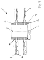
- 2 shows a plan view of a shaft element according to the invention
- 3 represents a section through FIG. 2 according to line III-III.
- FIG. 1 shows a section through a conventional filter 1, in which two hollow shafts 2 can be seen.
- Per hollow shaft are here clearer Representation of two filter disks 3 each shown, however entire filter is equipped with such discs 3. Looks particularly good one here that the two end parts 4, 4 'with several tie rods 5, 5' have to be held together. Now becomes a damaged one Filter disc replaced, all tie rods 5, 5 'must be loosened and the Hollow shafts 2 are completely removed. Then then the still intact filter disks 3 from one end until the damaged filter disc is reached, which can then be replaced. Then the filter is to be reassembled accordingly, which is one means a lot of time.
- Fig. 2 shows a plan view of a shaft element according to the invention 1 'with a hollow shaft 2 and filter or sorting discs 3.
- the Filter or sorting discs 3 can be filter or sorting surfaces Ceramic, metal or other materials, e.g. Plastic. Depending on the application, hole, pore or slot widths can be used from ⁇ 50 ⁇ m over several 100 ⁇ m up to approx. 2-5 mm.
- the diameter of the hollow shaft 2 becomes in accordance with the permeate flow selected, which results in clear differences in diameter result when used as a filtration or sorting machine.
- the fastening points 6 for example welding points
- the locking mechanism 7 is also for a two-part design of the filter or sorting disc 3 is shown. Furthermore, the bolt 8 with its over the hollow shaft body outstanding pieces 9 recognizable, through which the positive connection between the individual shaft elements 1 'as a bayonet catch is executed.
- Fig. 3 is the section through the shaft element 1 'according to line III-III in Fig. 2 shown.
- the shaft element 1 'shown has two filter disks 3, but also one or more as required Disks can be provided.
- the when using filter or Sorting discs 3 provided drain openings 10 in the cavity of the Hollow shaft 2 can be omitted for blind elements.
- the bolt end 9 can be seen at the upper end.
- the friction surface 12 is also shown here both at the upper and at the lower end of the shaft element 1 '. to Sealing of the liquid flow between the shaft elements 1 'are Sealing rings 13 are provided.
- Sealing rings 13 are provided.
Landscapes
- Chemical & Material Sciences (AREA)
- Chemical Kinetics & Catalysis (AREA)
- Engineering & Computer Science (AREA)
- Manufacturing & Machinery (AREA)
- Filtration Of Liquid (AREA)
- Centrifugal Separators (AREA)
- Separation Using Semi-Permeable Membranes (AREA)
- Filters For Electric Vacuum Cleaners (AREA)
- Apparatus Associated With Microorganisms And Enzymes (AREA)
Abstract
Description
Claims (8)
- Filter oder Sortierer, beispielsweise Membranfilter, mit auf einer Hohlwelle angeordneten Filter- oder Sortierscheiben, dadurch gekennzeichnet, dass die Hohlwelle (2) aus mehreren Wellenelementen (1') zusammengesetzt ist.
- Filter oder Sortierer, nach Anspruch 1, dadurch gekennzeichnet, dass ein Wellenelement (1') ein bis mehrere, vornehmlich zwei bis vier Filteroder Sortierscheiben (3) aufweist.
- Filter oder Sortierer nach Anspruch 1 oder 2, dadurch gekennzeichnet, dass die einzelnen Wellenelemente (1') zusammensteckbar ausgeführt sind.
- Filter oder Sortierer nach einem der Ansprüche 1 bis 3, dadurch gekennzeichnet, dass die Verbindung der Wellenelemente (1') mittels eines Bajonettverschlusses (8, 10) erfolgt.
- Filter oder Sortierer nach einem der Ansprüche 1 bis 4, dadurch gekennzeichnet, dass die Torsionskraft mittels Formschluss (8, 10) übertragen wird.
- Filter oder Sortierer nach einem der Ansprüche 1 bis 5, dadurch gekennzeichnet, dass die Torsionskraft mittels Reibschluss (11) übertragen wird.
- Filter oder Sortierer nach einem der Ansprüche 1 bis 6, dadurch gekennzeichnet, dass zwischen den einzelnen Wellenelementen (1') Dichtringe (12) vorgesehen sind.
- Filter oder Sortierer nach einem der Ansprüche 1 bis 7, dadurch gekennzeichnet, dass zwischen den mit Filterscheiben (3) versehenen Wellenelementen (1') zusätzlich Wellenelemente ohne Filterscheiben (Blindsegmente) vorgesehen sind.
Applications Claiming Priority (2)
| Application Number | Priority Date | Filing Date | Title |
|---|---|---|---|
| AT0091902A AT411574B (de) | 2002-06-19 | 2002-06-19 | Filter oder sortierer |
| AT9192002 | 2002-06-19 |
Publications (2)
| Publication Number | Publication Date |
|---|---|
| EP1374966A1 true EP1374966A1 (de) | 2004-01-02 |
| EP1374966B1 EP1374966B1 (de) | 2007-07-25 |
Family
ID=27625621
Family Applications (1)
| Application Number | Title | Priority Date | Filing Date |
|---|---|---|---|
| EP03011795A Expired - Lifetime EP1374966B1 (de) | 2002-06-19 | 2003-05-24 | Filter oder Sortierer |
Country Status (6)
| Country | Link |
|---|---|
| US (1) | US20040020838A1 (de) |
| EP (1) | EP1374966B1 (de) |
| CN (1) | CN100522310C (de) |
| AT (2) | AT411574B (de) |
| CA (1) | CA2429873A1 (de) |
| DE (1) | DE50307752D1 (de) |
Cited By (4)
| Publication number | Priority date | Publication date | Assignee | Title |
|---|---|---|---|---|
| WO2010053903A2 (en) | 2008-11-04 | 2010-05-14 | 3M Innovative Properties Company | Fluid interconnect |
| EP2450092A1 (de) * | 2010-11-05 | 2012-05-09 | Grundfos Management A/S | Filterstapel für eine Filterpumpe |
| WO2013083401A1 (de) * | 2011-12-09 | 2013-06-13 | Voith Patent Gmbh | Scheibenfilter-hohlwelle |
| WO2023073078A1 (de) * | 2021-10-29 | 2023-05-04 | Kerafol Holding Gmbh | Filtereinrichtung zum filtern eines suspensionsartigen stoffgemischs |
Families Citing this family (7)
| Publication number | Priority date | Publication date | Assignee | Title |
|---|---|---|---|---|
| US10918985B2 (en) | 2008-11-04 | 2021-02-16 | 3M Innovative Properties Company | Filter element and seal therefor |
| CA2812125A1 (en) * | 2009-07-24 | 2011-01-24 | Suncor Energy Inc. | Screening disk, roller, and roller screen for screening an ore feed |
| CN103638733B (zh) * | 2013-12-20 | 2015-04-29 | 中冶京诚工程技术有限公司 | 陶瓷盘式过滤机 |
| CN110404331B (zh) * | 2018-04-27 | 2024-02-20 | 芜湖美的厨卫电器制造有限公司 | 复合滤芯和净水设备 |
| US11000791B2 (en) * | 2019-03-06 | 2021-05-11 | Veolia Water Solutions & Technologies Support | Rotary disc filter having backwash guides |
| US12220657B2 (en) * | 2021-04-30 | 2025-02-11 | Pall Corporation | Filter disk segments |
| CN119656691B (zh) * | 2024-12-10 | 2025-11-07 | 常州辉途智能科技有限公司 | 智慧渔业水循环装置、循环控制系统及控制方法 |
Citations (4)
| Publication number | Priority date | Publication date | Assignee | Title |
|---|---|---|---|---|
| DE594953C (de) * | 1930-05-31 | 1934-03-23 | Buckau R Wolf Akt Ges Maschf | Saugzellen-Scheibendrehfilter |
| DE2249468A1 (de) * | 1972-10-09 | 1974-04-18 | Bhs Bayerische Berg | Druckfiltereinrichtung |
| EP0126213A2 (de) * | 1983-05-20 | 1984-11-28 | Uhde GmbH | Welle zur Bildung eines Filterpaketes eines Druckrotationsfilters |
| DE29518534U1 (de) * | 1995-11-22 | 1996-01-18 | Geldmacher, Joachim, Dipl.-Ing., 51588 Nümbrecht | Filter zum kontinuierlichen Filtern von Feststoffe aufweisenden Flüssigkeiten |
Family Cites Families (16)
| Publication number | Priority date | Publication date | Assignee | Title |
|---|---|---|---|---|
| US1639133A (en) * | 1926-01-25 | 1927-08-16 | Oscar V Greene | Filter element |
| US3055503A (en) * | 1958-10-29 | 1962-09-25 | Everpure | Water purifying apparatus |
| DE2729133A1 (de) * | 1976-06-30 | 1978-01-12 | Alfred John Kane | Plattenfilteranordnung |
| US4257894A (en) * | 1978-11-02 | 1981-03-24 | Celanese Corporation | Filter core extender and seal |
| DE3442870A1 (de) * | 1984-11-24 | 1986-05-28 | Schenk Filterbau Gmbh, 7076 Waldstetten | Rotationsscheibenfilterelement |
| DE3517032A1 (de) * | 1985-05-11 | 1986-11-13 | Heinkel Industriezentrifugen GmbH + Co, 7120 Bietigheim-Bissingen | Auspressfilter fuer suspensionen |
| SE459475B (sv) * | 1987-11-12 | 1989-07-10 | Asea Atom Ab | Anordning foer separation av i ett filter avskiljbara bestaandsdelar fraan ett vaetskeformigt medium innehaallande saadana bestaandsdelar |
| DE9104669U1 (de) * | 1991-04-17 | 1991-07-04 | Heinrich Fiedler GmbH & Co. KG, 8400 Regensburg | Aus einzelnen Scheibenfiltersegmenten bestehendes Scheibenfilter |
| EP0642315B1 (de) * | 1992-05-26 | 1997-02-12 | BERSTEN, Ian Jeffrey | Kaffeemaschine mit einem in zwei phasen arbeitenden kolben |
| DE19602349C2 (de) * | 1996-01-24 | 1997-12-11 | Schenk Filterbau Gmbh | Scheibenfilter |
| DE19744574B4 (de) * | 1997-10-09 | 2005-12-22 | Schenk-Filterbau Gmbh | Filtermodul |
| AT406936B (de) * | 1999-02-08 | 2000-10-25 | Andritz Patentverwaltung | Verfahren und vorrichtung zur querstromfiltration |
| US6467481B1 (en) * | 1999-04-29 | 2002-10-22 | Vase Technology | Stackable filter device |
| DE10019674A1 (de) * | 2000-04-19 | 2001-10-31 | Aaflowsystems Gmbh & Co Kg | Vorrichtung zur Querstrom-Filtration mittels Membranen |
| AT408842B (de) * | 2000-07-13 | 2002-03-25 | Andritz Ag Maschf | Filter |
| JP2002126800A (ja) * | 2000-10-24 | 2002-05-08 | Mitsubishi Kakoki Kaisha Ltd | 回転円板型濾過装置 |
-
2002
- 2002-06-19 AT AT0091902A patent/AT411574B/de not_active IP Right Cessation
-
2003
- 2003-05-24 AT AT03011795T patent/ATE367852T1/de not_active IP Right Cessation
- 2003-05-24 DE DE50307752T patent/DE50307752D1/de not_active Expired - Fee Related
- 2003-05-24 EP EP03011795A patent/EP1374966B1/de not_active Expired - Lifetime
- 2003-05-27 CA CA002429873A patent/CA2429873A1/en not_active Abandoned
- 2003-06-17 US US10/464,107 patent/US20040020838A1/en not_active Abandoned
- 2003-06-18 CN CNB031491804A patent/CN100522310C/zh not_active Expired - Fee Related
Patent Citations (4)
| Publication number | Priority date | Publication date | Assignee | Title |
|---|---|---|---|---|
| DE594953C (de) * | 1930-05-31 | 1934-03-23 | Buckau R Wolf Akt Ges Maschf | Saugzellen-Scheibendrehfilter |
| DE2249468A1 (de) * | 1972-10-09 | 1974-04-18 | Bhs Bayerische Berg | Druckfiltereinrichtung |
| EP0126213A2 (de) * | 1983-05-20 | 1984-11-28 | Uhde GmbH | Welle zur Bildung eines Filterpaketes eines Druckrotationsfilters |
| DE29518534U1 (de) * | 1995-11-22 | 1996-01-18 | Geldmacher, Joachim, Dipl.-Ing., 51588 Nümbrecht | Filter zum kontinuierlichen Filtern von Feststoffe aufweisenden Flüssigkeiten |
Cited By (7)
| Publication number | Priority date | Publication date | Assignee | Title |
|---|---|---|---|---|
| WO2010053903A2 (en) | 2008-11-04 | 2010-05-14 | 3M Innovative Properties Company | Fluid interconnect |
| EP2373394A4 (de) * | 2008-11-04 | 2012-05-30 | 3M Innovative Properties Co | Fluidverbindung |
| EP2450092A1 (de) * | 2010-11-05 | 2012-05-09 | Grundfos Management A/S | Filterstapel für eine Filterpumpe |
| WO2012059356A1 (de) * | 2010-11-05 | 2012-05-10 | Grundfos Management A/S | Filterstapel für eine filterpumpe |
| WO2013083401A1 (de) * | 2011-12-09 | 2013-06-13 | Voith Patent Gmbh | Scheibenfilter-hohlwelle |
| AT13953U1 (de) * | 2011-12-09 | 2015-01-15 | Voith Patent Gmbh | Scheibenfilter-Hohlwelle |
| WO2023073078A1 (de) * | 2021-10-29 | 2023-05-04 | Kerafol Holding Gmbh | Filtereinrichtung zum filtern eines suspensionsartigen stoffgemischs |
Also Published As
| Publication number | Publication date |
|---|---|
| AT411574B (de) | 2004-03-25 |
| ATA9192002A (de) | 2003-08-15 |
| CA2429873A1 (en) | 2003-12-19 |
| ATE367852T1 (de) | 2007-08-15 |
| US20040020838A1 (en) | 2004-02-05 |
| CN100522310C (zh) | 2009-08-05 |
| DE50307752D1 (de) | 2007-09-06 |
| CN1470306A (zh) | 2004-01-28 |
| EP1374966B1 (de) | 2007-07-25 |
Similar Documents
| Publication | Publication Date | Title |
|---|---|---|
| EP2222382B1 (de) | Filtereinrichtung, insbesondere flüssigkeitsfilter | |
| EP1918576B1 (de) | Kraftstofffilter | |
| EP3448542B1 (de) | Filterelement zur filtration von abgasen oder prozessgasen sowie verfahren zur herstellung eines solchen filterelementes | |
| DE112017001107T5 (de) | Filterelement | |
| WO2001091884A1 (de) | Filtereinrichtung | |
| AT411574B (de) | Filter oder sortierer | |
| EP3680003B1 (de) | Filterpatrone mit venturi-düse | |
| DE19943467B4 (de) | Filter mit ebenem Filtereinsatz | |
| EP3932515A1 (de) | Rotationsscheibenfilter | |
| EP1159998A2 (de) | Flüssigkeitsfilter | |
| EP1777339A1 (de) | Siebvorrichtung zur Nasssiebung von Papierfasersuspensionen | |
| DE102013012917A1 (de) | Flüssigkeitsfilter, insbesondere für Kraftstoff | |
| EP4306198A1 (de) | Filter mit v-förmig angeordneten medienpaketen und schutzgitter | |
| EP2749335B1 (de) | Zweiteiliger Partikelfilter | |
| EP0830886A1 (de) | Filtermaterial sowie Filter zum Filtrieren von Flüssigkeiten oder Gasen | |
| EP2481474B1 (de) | Dichtungsanordnung für stabförmige keramische Filterelemente | |
| WO2012059356A1 (de) | Filterstapel für eine filterpumpe | |
| DE60009429T2 (de) | Filtervorrichtung für Schwimmbecken | |
| DE102007003926A1 (de) | Filteranlage | |
| DE102006045136B3 (de) | Filtervorrichtung und Verfahren zum Herstellen einer Filtervorrichtung | |
| EP4032597B1 (de) | Ringfilterelement und flüssigfiltereinrichtung | |
| DE102010064180A1 (de) | Filtereinrichtung | |
| AT528417B1 (de) | Filtervorrichtung zum Filtern von Polymerschmelze | |
| DE3639662C1 (de) | Stuetzkorb fuer Filterschlaeuche | |
| DE3015370A1 (de) | Siebkorb fuer sortierer der papierindustrie |
Legal Events
| Date | Code | Title | Description |
|---|---|---|---|
| PUAI | Public reference made under article 153(3) epc to a published international application that has entered the european phase |
Free format text: ORIGINAL CODE: 0009012 |
|
| AK | Designated contracting states |
Kind code of ref document: A1 Designated state(s): AT BE BG CH CY CZ DE DK EE ES FI FR GB GR HU IE IT LI LU MC NL PT RO SE SI SK TR |
|
| AX | Request for extension of the european patent |
Extension state: AL LT LV MK |
|
| 17P | Request for examination filed |
Effective date: 20040319 |
|
| AKX | Designation fees paid |
Designated state(s): AT BE BG CH CY CZ DE DK EE ES FI FR GB GR HU IE IT LI LU MC NL PT RO SE SI SK TR |
|
| GRAP | Despatch of communication of intention to grant a patent |
Free format text: ORIGINAL CODE: EPIDOSNIGR1 |
|
| GRAS | Grant fee paid |
Free format text: ORIGINAL CODE: EPIDOSNIGR3 |
|
| GRAA | (expected) grant |
Free format text: ORIGINAL CODE: 0009210 |
|
| AK | Designated contracting states |
Kind code of ref document: B1 Designated state(s): AT BE BG CH CY CZ DE DK EE ES FI FR GB GR HU IE IT LI LU MC NL PT RO SE SI SK TR |
|
| REG | Reference to a national code |
Ref country code: GB Ref legal event code: FG4D Free format text: NOT ENGLISH |
|
| REG | Reference to a national code |
Ref country code: CH Ref legal event code: EP |
|
| REG | Reference to a national code |
Ref country code: IE Ref legal event code: FG4D Free format text: LANGUAGE OF EP DOCUMENT: GERMAN |
|
| REF | Corresponds to: |
Ref document number: 50307752 Country of ref document: DE Date of ref document: 20070906 Kind code of ref document: P |
|
| PG25 | Lapsed in a contracting state [announced via postgrant information from national office to epo] |
Ref country code: PT Free format text: LAPSE BECAUSE OF FAILURE TO SUBMIT A TRANSLATION OF THE DESCRIPTION OR TO PAY THE FEE WITHIN THE PRESCRIBED TIME-LIMIT Effective date: 20071226 Ref country code: ES Free format text: LAPSE BECAUSE OF FAILURE TO SUBMIT A TRANSLATION OF THE DESCRIPTION OR TO PAY THE FEE WITHIN THE PRESCRIBED TIME-LIMIT Effective date: 20071105 Ref country code: BG Free format text: LAPSE BECAUSE OF FAILURE TO SUBMIT A TRANSLATION OF THE DESCRIPTION OR TO PAY THE FEE WITHIN THE PRESCRIBED TIME-LIMIT Effective date: 20071025 Ref country code: NL Free format text: LAPSE BECAUSE OF FAILURE TO SUBMIT A TRANSLATION OF THE DESCRIPTION OR TO PAY THE FEE WITHIN THE PRESCRIBED TIME-LIMIT Effective date: 20070725 |
|
| NLV1 | Nl: lapsed or annulled due to failure to fulfill the requirements of art. 29p and 29m of the patents act | ||
| GBV | Gb: ep patent (uk) treated as always having been void in accordance with gb section 77(7)/1977 [no translation filed] |
Effective date: 20070725 |
|
| REG | Reference to a national code |
Ref country code: IE Ref legal event code: FD4D |
|
| EN | Fr: translation not filed | ||
| PG25 | Lapsed in a contracting state [announced via postgrant information from national office to epo] |
Ref country code: GR Free format text: LAPSE BECAUSE OF FAILURE TO SUBMIT A TRANSLATION OF THE DESCRIPTION OR TO PAY THE FEE WITHIN THE PRESCRIBED TIME-LIMIT Effective date: 20071026 Ref country code: DK Free format text: LAPSE BECAUSE OF FAILURE TO SUBMIT A TRANSLATION OF THE DESCRIPTION OR TO PAY THE FEE WITHIN THE PRESCRIBED TIME-LIMIT Effective date: 20070725 |
|
| PG25 | Lapsed in a contracting state [announced via postgrant information from national office to epo] |
Ref country code: CZ Free format text: LAPSE BECAUSE OF FAILURE TO SUBMIT A TRANSLATION OF THE DESCRIPTION OR TO PAY THE FEE WITHIN THE PRESCRIBED TIME-LIMIT Effective date: 20070725 Ref country code: IE Free format text: LAPSE BECAUSE OF FAILURE TO SUBMIT A TRANSLATION OF THE DESCRIPTION OR TO PAY THE FEE WITHIN THE PRESCRIBED TIME-LIMIT Effective date: 20070725 Ref country code: GB Free format text: LAPSE BECAUSE OF FAILURE TO SUBMIT A TRANSLATION OF THE DESCRIPTION OR TO PAY THE FEE WITHIN THE PRESCRIBED TIME-LIMIT Effective date: 20070725 Ref country code: SK Free format text: LAPSE BECAUSE OF FAILURE TO SUBMIT A TRANSLATION OF THE DESCRIPTION OR TO PAY THE FEE WITHIN THE PRESCRIBED TIME-LIMIT Effective date: 20070725 |
|
| PLBE | No opposition filed within time limit |
Free format text: ORIGINAL CODE: 0009261 |
|
| STAA | Information on the status of an ep patent application or granted ep patent |
Free format text: STATUS: NO OPPOSITION FILED WITHIN TIME LIMIT |
|
| PG25 | Lapsed in a contracting state [announced via postgrant information from national office to epo] |
Ref country code: RO Free format text: LAPSE BECAUSE OF FAILURE TO SUBMIT A TRANSLATION OF THE DESCRIPTION OR TO PAY THE FEE WITHIN THE PRESCRIBED TIME-LIMIT Effective date: 20070725 Ref country code: SE Free format text: LAPSE BECAUSE OF FAILURE TO SUBMIT A TRANSLATION OF THE DESCRIPTION OR TO PAY THE FEE WITHIN THE PRESCRIBED TIME-LIMIT Effective date: 20071025 |
|
| 26N | No opposition filed |
Effective date: 20080428 |
|
| PG25 | Lapsed in a contracting state [announced via postgrant information from national office to epo] |
Ref country code: FR Free format text: LAPSE BECAUSE OF FAILURE TO SUBMIT A TRANSLATION OF THE DESCRIPTION OR TO PAY THE FEE WITHIN THE PRESCRIBED TIME-LIMIT Effective date: 20080321 |
|
| PGFP | Annual fee paid to national office [announced via postgrant information from national office to epo] |
Ref country code: DE Payment date: 20080523 Year of fee payment: 6 |
|
| PGFP | Annual fee paid to national office [announced via postgrant information from national office to epo] |
Ref country code: FI Payment date: 20080514 Year of fee payment: 6 |
|
| BERE | Be: lapsed |
Owner name: ANDRITZ AG Effective date: 20080531 |
|
| PG25 | Lapsed in a contracting state [announced via postgrant information from national office to epo] |
Ref country code: MC Free format text: LAPSE BECAUSE OF NON-PAYMENT OF DUE FEES Effective date: 20080531 |
|
| REG | Reference to a national code |
Ref country code: CH Ref legal event code: PL |
|
| PG25 | Lapsed in a contracting state [announced via postgrant information from national office to epo] |
Ref country code: LI Free format text: LAPSE BECAUSE OF NON-PAYMENT OF DUE FEES Effective date: 20080531 Ref country code: CH Free format text: LAPSE BECAUSE OF NON-PAYMENT OF DUE FEES Effective date: 20080531 |
|
| PG25 | Lapsed in a contracting state [announced via postgrant information from national office to epo] |
Ref country code: BE Free format text: LAPSE BECAUSE OF NON-PAYMENT OF DUE FEES Effective date: 20080531 |
|
| PG25 | Lapsed in a contracting state [announced via postgrant information from national office to epo] |
Ref country code: EE Free format text: LAPSE BECAUSE OF FAILURE TO SUBMIT A TRANSLATION OF THE DESCRIPTION OR TO PAY THE FEE WITHIN THE PRESCRIBED TIME-LIMIT Effective date: 20070725 |
|
| PG25 | Lapsed in a contracting state [announced via postgrant information from national office to epo] |
Ref country code: SI Free format text: LAPSE BECAUSE OF FAILURE TO SUBMIT A TRANSLATION OF THE DESCRIPTION OR TO PAY THE FEE WITHIN THE PRESCRIBED TIME-LIMIT Effective date: 20070725 |
|
| PG25 | Lapsed in a contracting state [announced via postgrant information from national office to epo] |
Ref country code: CY Free format text: LAPSE BECAUSE OF FAILURE TO SUBMIT A TRANSLATION OF THE DESCRIPTION OR TO PAY THE FEE WITHIN THE PRESCRIBED TIME-LIMIT Effective date: 20070725 |
|
| PG25 | Lapsed in a contracting state [announced via postgrant information from national office to epo] |
Ref country code: AT Free format text: LAPSE BECAUSE OF NON-PAYMENT OF DUE FEES Effective date: 20080524 |
|
| PG25 | Lapsed in a contracting state [announced via postgrant information from national office to epo] |
Ref country code: FI Free format text: LAPSE BECAUSE OF NON-PAYMENT OF DUE FEES Effective date: 20090524 |
|
| PG25 | Lapsed in a contracting state [announced via postgrant information from national office to epo] |
Ref country code: DE Free format text: LAPSE BECAUSE OF NON-PAYMENT OF DUE FEES Effective date: 20091201 |
|
| PG25 | Lapsed in a contracting state [announced via postgrant information from national office to epo] |
Ref country code: HU Free format text: LAPSE BECAUSE OF FAILURE TO SUBMIT A TRANSLATION OF THE DESCRIPTION OR TO PAY THE FEE WITHIN THE PRESCRIBED TIME-LIMIT Effective date: 20080126 Ref country code: LU Free format text: LAPSE BECAUSE OF NON-PAYMENT OF DUE FEES Effective date: 20080524 |
|
| PG25 | Lapsed in a contracting state [announced via postgrant information from national office to epo] |
Ref country code: TR Free format text: LAPSE BECAUSE OF FAILURE TO SUBMIT A TRANSLATION OF THE DESCRIPTION OR TO PAY THE FEE WITHIN THE PRESCRIBED TIME-LIMIT Effective date: 20070725 |
|
| PG25 | Lapsed in a contracting state [announced via postgrant information from national office to epo] |
Ref country code: IT Free format text: LAPSE BECAUSE OF NON-PAYMENT OF DUE FEES Effective date: 20080531 |