EP1372500B1 - Knochenfixierte lastkontrollvorrichtung für gelenk - Google Patents
Knochenfixierte lastkontrollvorrichtung für gelenk Download PDFInfo
- Publication number
- EP1372500B1 EP1372500B1 EP02701426A EP02701426A EP1372500B1 EP 1372500 B1 EP1372500 B1 EP 1372500B1 EP 02701426 A EP02701426 A EP 02701426A EP 02701426 A EP02701426 A EP 02701426A EP 1372500 B1 EP1372500 B1 EP 1372500B1
- Authority
- EP
- European Patent Office
- Prior art keywords
- assembly
- fixation
- link
- joint
- fixation assembly
- Prior art date
- Legal status (The legal status is an assumption and is not a legal conclusion. Google has not performed a legal analysis and makes no representation as to the accuracy of the status listed.)
- Expired - Lifetime
Links
- 210000000988 bone and bone Anatomy 0.000 title claims abstract description 45
- 238000000926 separation method Methods 0.000 claims abstract description 27
- 241001465754 Metazoa Species 0.000 claims abstract description 4
- 210000001188 articular cartilage Anatomy 0.000 claims abstract description 4
- 230000000712 assembly Effects 0.000 claims description 33
- 238000000429 assembly Methods 0.000 claims description 33
- 238000006073 displacement reaction Methods 0.000 claims description 18
- 230000006835 compression Effects 0.000 claims description 10
- 238000007906 compression Methods 0.000 claims description 10
- 238000005452 bending Methods 0.000 claims description 7
- 230000015572 biosynthetic process Effects 0.000 claims description 2
- 230000008878 coupling Effects 0.000 claims 1
- 238000010168 coupling process Methods 0.000 claims 1
- 238000005859 coupling reaction Methods 0.000 claims 1
- 210000000845 cartilage Anatomy 0.000 description 11
- 230000002146 bilateral effect Effects 0.000 description 5
- 230000000694 effects Effects 0.000 description 3
- 210000003127 knee Anatomy 0.000 description 3
- 201000008482 osteoarthritis Diseases 0.000 description 3
- 238000002560 therapeutic procedure Methods 0.000 description 3
- 238000013461 design Methods 0.000 description 2
- 230000035876 healing Effects 0.000 description 2
- 238000002955 isolation Methods 0.000 description 2
- 239000000463 material Substances 0.000 description 2
- 238000000034 method Methods 0.000 description 2
- 230000008439 repair process Effects 0.000 description 2
- 210000001519 tissue Anatomy 0.000 description 2
- 206010002091 Anaesthesia Diseases 0.000 description 1
- 208000034189 Sclerosis Diseases 0.000 description 1
- 238000001949 anaesthesia Methods 0.000 description 1
- 230000037005 anaesthesia Effects 0.000 description 1
- 230000008859 change Effects 0.000 description 1
- 230000009977 dual effect Effects 0.000 description 1
- 230000036541 health Effects 0.000 description 1
- 239000007943 implant Substances 0.000 description 1
- 238000011065 in-situ storage Methods 0.000 description 1
- 238000009434 installation Methods 0.000 description 1
- 210000000629 knee joint Anatomy 0.000 description 1
- 230000007774 longterm Effects 0.000 description 1
- 238000005259 measurement Methods 0.000 description 1
- 230000007246 mechanism Effects 0.000 description 1
- 230000003278 mimic effect Effects 0.000 description 1
- 210000002346 musculoskeletal system Anatomy 0.000 description 1
- 230000003349 osteoarthritic effect Effects 0.000 description 1
- 238000011160 research Methods 0.000 description 1
- 230000004044 response Effects 0.000 description 1
- 206010039073 rheumatoid arthritis Diseases 0.000 description 1
- 230000000638 stimulation Effects 0.000 description 1
- 238000001356 surgical procedure Methods 0.000 description 1
Images


Classifications
-
- A—HUMAN NECESSITIES
- A61—MEDICAL OR VETERINARY SCIENCE; HYGIENE
- A61B—DIAGNOSIS; SURGERY; IDENTIFICATION
- A61B17/00—Surgical instruments, devices or methods
- A61B17/56—Surgical instruments or methods for treatment of bones or joints; Devices specially adapted therefor
- A61B17/58—Surgical instruments or methods for treatment of bones or joints; Devices specially adapted therefor for osteosynthesis, e.g. bone plates, screws or setting implements
- A61B17/60—Surgical instruments or methods for treatment of bones or joints; Devices specially adapted therefor for osteosynthesis, e.g. bone plates, screws or setting implements for external osteosynthesis, e.g. distractors, contractors
- A61B17/64—Devices extending alongside the bones to be positioned
- A61B17/6425—Devices extending alongside the bones to be positioned specially adapted to be fitted across a bone joint
-
- A—HUMAN NECESSITIES
- A61—MEDICAL OR VETERINARY SCIENCE; HYGIENE
- A61B—DIAGNOSIS; SURGERY; IDENTIFICATION
- A61B17/00—Surgical instruments, devices or methods
- A61B17/56—Surgical instruments or methods for treatment of bones or joints; Devices specially adapted therefor
- A61B17/58—Surgical instruments or methods for treatment of bones or joints; Devices specially adapted therefor for osteosynthesis, e.g. bone plates, screws or setting implements
- A61B17/60—Surgical instruments or methods for treatment of bones or joints; Devices specially adapted therefor for osteosynthesis, e.g. bone plates, screws or setting implements for external osteosynthesis, e.g. distractors, contractors
- A61B17/64—Devices extending alongside the bones to be positioned
- A61B17/6416—Devices extending alongside the bones to be positioned with non-continuous, e.g. hinged, pin-clamp connecting element
-
- A—HUMAN NECESSITIES
- A61—MEDICAL OR VETERINARY SCIENCE; HYGIENE
- A61B—DIAGNOSIS; SURGERY; IDENTIFICATION
- A61B17/00—Surgical instruments, devices or methods
- A61B17/56—Surgical instruments or methods for treatment of bones or joints; Devices specially adapted therefor
- A61B17/58—Surgical instruments or methods for treatment of bones or joints; Devices specially adapted therefor for osteosynthesis, e.g. bone plates, screws or setting implements
- A61B17/60—Surgical instruments or methods for treatment of bones or joints; Devices specially adapted therefor for osteosynthesis, e.g. bone plates, screws or setting implements for external osteosynthesis, e.g. distractors, contractors
- A61B17/64—Devices extending alongside the bones to be positioned
- A61B17/6441—Bilateral fixators, i.e. with both ends of pins or wires clamped
-
- A—HUMAN NECESSITIES
- A61—MEDICAL OR VETERINARY SCIENCE; HYGIENE
- A61B—DIAGNOSIS; SURGERY; IDENTIFICATION
- A61B17/00—Surgical instruments, devices or methods
- A61B17/56—Surgical instruments or methods for treatment of bones or joints; Devices specially adapted therefor
- A61B17/58—Surgical instruments or methods for treatment of bones or joints; Devices specially adapted therefor for osteosynthesis, e.g. bone plates, screws or setting implements
- A61B17/60—Surgical instruments or methods for treatment of bones or joints; Devices specially adapted therefor for osteosynthesis, e.g. bone plates, screws or setting implements for external osteosynthesis, e.g. distractors, contractors
- A61B2017/606—Surgical instruments or methods for treatment of bones or joints; Devices specially adapted therefor for osteosynthesis, e.g. bone plates, screws or setting implements for external osteosynthesis, e.g. distractors, contractors with resilient spring element
Definitions
- the present invention relates to devices for restricting or controlling the movement or loading levels on joints in the human or animal body.
- the human or animal body uses articular cartilage to surface many of its joints. This tissue tolerates relatively high levels of compression while having a low coefficient of friction - approximately that of wet ice on wet ice.
- Bone, on which the cartilage is supported, is stiffer and stronger. Away from the joints, bone normally forms in large, thick-walled tubes. However, under the cartilage at the joints, the bone forms a three dimensional mesh of so called “cancellous" bone. Cancellous bone is more compliant than the rest of the bone structure and helps spread the load that the cartilage experiences, thus reducing the peak stresses on the cartilage.
- Joint surfaces can and do last a lifetime and if they experience healthy levels of load they can be considered to effectively last indefinitely.
- both bone and cartilage begin to show signs of failure at loads that are below their ultimate strength.
- cartilage and bone have some ability to repair themselves, bone more so.
- osteoarthritis One of the major consequences of excessive loading is osteoarthritis. This loading could be either from a single overload in the overloaded zone or from loading within the tolerant zone too frequently.
- the picture of safe joint loading is further complicated by the cascade of events that occur during the onset of osteoarthritis. These events include the break up of the cartilage, and bone 'sclerosis' in which the bone becomes denser and stiffer. This means that the maximum level of loading that can be considered healthy or tolerated falls, almost certainly to levels below that experienced in walking and standing.
- Newly implanted grafts or tissue-engineered constructs will also have lower tolerance limits while they are establishing themselves within the joint.
- a device to preferably provide such control while allowing full, or relatively full mobility of a patient undergoing the treatment.
- Such devices would be desirable particularly during the early treatment of, for example, an osteoarthritic joint. Under an appropriate treatment regime providing controlled loading, the condition of the joint may improve, possibly back to full health.
- EP 0 953 317 on which the preamble of claim 1 is based concerns a skeletal implant device consisting of a first and second end components connected to bone anchors and equipped with a deformable member.
- An intermediate component provides for a non-rectilinear movement, especially a rotation, between the anchors when the deformable member is actuated.
- WO 96 19944 concerns an articulation support device composed by two fundamental elements, a measuring device allowing the continuous recording of six parameters fully describing the relative motion between its extremes, and an articulation fixator, both supplied at each end by reference slots.
- the present invention provides an apparatus as claimed in claim 1.
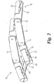
- FIG. 1 there is shown an articulated joint load controlling device or fixator 10 according to one embodiment of the invention.
- the fixator 10 comprises a first fixation assembly 11, a second fixation assembly 12 and a link assembly 13 connecting the first and second fixation assemblies 11, 12.
- the first and second fixation assemblies 11, 12 are each coupled to the link assembly 13 by a joint 14, 15 or other equivalent means facilitating angular displacement of the respective fixation assembly to the link assembly.
- joint is intended to encompass all such equivalent means for facilitating angular displacement. It will be understood that the first and second fixation assemblies 11, 12 are therefore not only angularly displaceable relative to one another, but are also capable of some relative translational movement subject to the geometric limitations provided by the link assembly 13.
- the axes of the joints 14, 15 are parallel so that the first and second fixation assemblies 11, 12 will rotate about the link assembly in the same plane.
- the joints 14 and 15 might not be axially parallel, in order to better follow the three-dimensional movement of a particular joint.
- one or both joints 14, 15 might be of the universal joint type, such that the pivot allows two degrees of rotational freedom rather than only a single degree of rotational freedom, in order to better follow the three-dimensional movement of, for example, a ball joint.
- Each fixation assembly 11, 12 preferably comprises a faceplate 20 having one or more slots 21 defined in the faceplate surface. Coupled to the faceplate 20 is a clamp plate 22 which may be tightened onto the faceplate 20 by way of screws, or other means known in the art. Preferably, the clamp plate includes corresponding slots 23. As shown more clearly in figure 2 , the face plate 20 and clamp plate 22 together provide an anchorage for one or more bone pins 30 which can be screwed into or otherwise fixed to a bone using known techniques. Other examples of fixation assemblies are illustrated later in connection with figure 5 .
- a single load controlling fixator 10 may be attached to an articulating joint by way of first bone pins 30 screwed into one side of a first bone using the first fixation assembly 11, and second bone pins 30 screwed into a corresponding side of a second bone using the second fixation assembly 12.
- the first and second bones are on either side of an articulating joint to be controlled by the fixator.
- two load controlling devices or fixators may be used in a bilateral configuration on either side of an articulating joint, the bone pins 30 passing right through the respective first and second bones on either side of the articulating joint.
- first and second fixation assemblies 11, 12 of a fixator 10 might be coupled to two or more link assemblies in series or in parallel with one another.
- a fixator 16 comprises a first fixation assembly 11 and a second fixation assembly 12 that are connected by a link assembly that comprises a pair of link members 18, 19 in a parallel-crosswise configuration.
- Each link member is pivotally anchored to both the first and second fixation assemblies 11, 12 by way of face plates 17, the link members being laterally displaced from one another.
- the link member 18 and link member 19 are not only laterally displaced from one another, but also angularly displaced from one another, in a crosswise formation. This arrangement provides a controlled, limited degree of freedom of relative movement of the first and second fixation assemblies. By adjusting the position of the two link members it is possible to mimic the movement of the knee.
- the link assembly 40 comprises a rigid, fixed length member having a barrel centre section 41 and a pair of lugs 44 extending from each end.
- Each pair of lugs 44 includes a pair of coaxial apertures or hubs 42, 43 in which can rotate respective pivot pins 14, 15 ( figure 1 ).
- Each pair of lugs 44 define therebetween a slot 45 adapted to receive a corresponding lug 25 (see figure 1 ) of a respective fixation assembly 11 or 12.
- the link assembly 40 essentially maintains first and second joints 14 and 15 at a fixed distance of separation.
- the lug pairs 44 and barrel centre section 41 may be screwed together for quick disassembly and re-assembly, enabling different length barrel centre sections 41 to readily be used to provide a link assembly 40 of an appropriate length to the joint under treatment or therapy and to be changed during a treatment program.
- a link assembly 50 provides for a variable distance of separation of joints 14, 15 in hubs 52, 53.
- Link assembly 50 comprises a pair of lugs 54 and a pair of lugs 55, each pair being mounted on a central shaft 56 and being axially displaceable therealong.
- a pair of tension springs 57, 58 provide a means for biasing the distance of separation of the joints 14, 15 towards a minimum limit of separation of the lug pairs 54, 55 to apply greater compression forces than those normally experienced by the joint.
- a link assembly 60 provides for a variable distance of separation of joints 14, 15 in hubs 62, 63.
- Link assembly 60 comprises a pair of lugs 64 and a pair of lugs 65, each pair being mounted on a central shaft 66 and being axially displaceable therealong.
- a compression spring 67 provides a means for biasing the distance of separation of the joints 14, 15 towards a maximum limit of separation of the lug pairs 64, 65 so as to counteract the natural compressive forces experienced by the joint.
- link assembly 50 and link assembly 60 may be combined to provide bias towards a central position so that there is resistance against movement of the pairs of lugs from a centre position. More generally, this provides means for biasing the first and second pivots towards an intermediate distance of separation between predetermined limits of separation of the lug pairs 54, 55 or 64, 65.
- a locking member which is axially adjustable along the length of the link assembly to adjust the limit or limits of separation of the lug pairs.
- the locking member could be provided, for example, by way of a screw-threaded collar on the central shaft 56 or 66 using techniques that will be understood by those skilled in the art.
- a means for controlling the distance of separation of joints 14, 15 could be by way of a link assembly 80 that includes a pneumatic or hydraulic cylinder 81, controlled externally by a controller (not shown) connected thereto by two feed pipes 82, 83.
- the pneumatic or hydraulic cylinder may also provide means for biasing the distance of separation of the first and second pivots to a predetermined position.
- the link assembly 70 (which may generally correspond with a links 50 or 60 having variable separation members) may also be provided with a mechanism for varying the distance of separation of the joints 14, 15 according to the angular displacement of the first and/or second fixation assemblies relative to the link assembly. This would enable, for example, the separation to be increased in the last 5° of angular displacement.
- a cam surface 76, 77 is provided on the circumferential edge of one or both of the lug pairs 74, 75.
- the cam surface bears on a corresponding bearing surface on a respective fixation assembly 11, 12 and is preferably adapted to vary the separation of the fixation assemblies as a function of the angular displacement.
- the cam surfaces 76, 77 can be arranged so that as the knee is moved to the fully extended condition, the fixator ensures a greater separation of the fixation assemblies 11, 12 thereby reducing pressure on the joint surfaces.
- cam surfaces 76, 77 could be adapted to limit the angular displacement of that fixation assembly.
- the cam surfaces may be used to provide a varying degree of resistance to angular displacement of the fixation assembly. More generally, the cam surface may be adapted to provide a means for progressively increasing resistance to angular displacement of the fixation assembly relative to the link assembly as a function of the angular displacement from a reference position.
- the means for limiting angular displacement could alternatively be provided by a stepped surface on the circumferential edge of the lug in a manner which will be understood by those skilled in the art.
- a link assembly 90 as shown in figure 3B may be provided with means for recording loads applied across the link assembly.
- the sensor may be adapted to monitor any one or more of the tensile load, the compression load, shear forces or bending forces applied across the link assembly.
- the sensor comprises a strain gauge.
- Such a device makes it possible to determine the load actually being carried by a joint. In the preferred embodiment shown, this is achieved by the installation of strain gauges 92 into the barrel 93 of the link assembly 90.
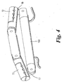
- the angular displacement of the fixation assemblies relative to one another may be controlled externally. This can be achieved by a linear actuator 100 linked to the first and second fixation assemblies 11, 12 by way of brackets 17, 18 each extending from a respective fixation assembly in a direction orthogonal to the pivot axis.
- the linear actuator 100 may be powered electrically, pneumatically or hydraulically and enables movement of a joint to be automatically controlled for exercise within the healthy load zone without use of the associated musculature.
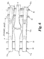
- FIG. 6 a bilateral configuration of fixation assemblies is shown similar to that of figure 2 , viewed from above (ie. generally perpendicular to the pivot axles).
- fixation assemblies 11a, 12a and 11b, 12b are respectively connected by link assemblies 13a, 13b.
- a unilateral adjustment of the length of link assembly 13b results in a relative angular displacement of the bones 4, 5 that varies with articulation of the bones about the axis of the joint, thereby imposing an angulation on the joint. This will tend to have the effect of reducing the load experienced at the joint surface on the side nearest to the lengthened segment.
- FIG. 5A shows a fixation assembly 110 have a lug 25 for attachment to the various possible link assemblies 13, 40, 50, 60, 70, 80, 90.
- the body of the fixation assembly includes a plurality of apertures 111a, 111b, 111c each adapted to receive a bone pin 30.
- each aperture is defined in a corresponding rotatable collar 112a, 112b, 112c such that the angles of the bone pins 30 may be varied on and about the central longitudinal axis of the fixation assembly 110.
- the fixation assembly 120 as shown in figure 5b is similar to that of figure 5a , except that in this case the apertures 121a, 121b, 121c are laterally offset from the central longitudinal axis of the fixation assembly.
- Each aperture is again defined in a corresponding rotatable collar 122a, 122b, 122c so that the angles of the bone pins 30 may be varied about a longitudinal axis that is laterally displaced from the central longitudinal axis of the fixation assembly 120.
- the fixation assembly 130 as shown in figure 5c provides a further degree of freedom.
- bone pins 30 are located in slots 131 formed between a first clamp plate 132 and a second clamp plate 133.
- the clamp plates 132, 133 are rotatable about a first axis (transverse to a longitudinal axis of the fixation assembly 130) on pivot 134, and about a second axis (preferably a longitudinal axis of the fixation assembly 130) on pivot 135. Taken together with the pivot through aperture 136, this provides a full three rotational degrees of freedom of the bone relative to a link assembly.
- fixator device embodiments as generally described above therefore provide a means for applying and/or limiting tension, compression, torsion, bending and shear forces to an articulated joint in a controlled manner and provide for some or all of the following treatment regimes either in isolation or in any combination. Also it will be possible to change the regime or combination of regimes easily and without the need for a sterile environment or anaesthesia. It is noted that joints of the skeleton naturally experience compression and the fixators of the present invention can provide amelioration of this by applying tension.
- the level of tension can be varied according to the length of the link assembly used and this can be further varied according to the bias strengths applied by the springs 57, 58, 67.
- Some or all of the compression that would otherwise be carried by the joint may be taken by the device, and this can be a function of the angle of support by control of spring strength and angle of fixation to the bones.
- the device as described in connection with figure 3B allows the clinician to detect and record the loads experienced across a joint, and also the load applied across the joint by the device.
- the motive forces applied across the joints may be from normal physiological loads of the musculoskeletal system or from an externally applied source such as described with reference to figure 4 .
- the preferred design of the devices described above enable the link assemblies and fixation assemblies to be readily disconnected from the bone pins 30 in order to replace or adjust the devices during a treatment schedule. Still further, in the preferred designs, the link assemblies may be adjusted in situ. Preferably, the devices will be able to be removed in their entirety within an outpatient clinic.
- the articulated joint controlling devices of the present invention can be used in the treatment not only of rheumatoid arthritis, but for the treatment of many other conditions such as articular fractures, and following surgical procedures such as osteochondral transfers and joint surface replacement with cartilage graft.
Landscapes
- Health & Medical Sciences (AREA)
- Orthopedic Medicine & Surgery (AREA)
- Life Sciences & Earth Sciences (AREA)
- Surgery (AREA)
- Animal Behavior & Ethology (AREA)
- Veterinary Medicine (AREA)
- Biomedical Technology (AREA)
- Heart & Thoracic Surgery (AREA)
- Medical Informatics (AREA)
- Molecular Biology (AREA)
- Nuclear Medicine, Radiotherapy & Molecular Imaging (AREA)
- General Health & Medical Sciences (AREA)
- Public Health (AREA)
- Engineering & Computer Science (AREA)
- Surgical Instruments (AREA)
- Prostheses (AREA)
- Thermotherapy And Cooling Therapy Devices (AREA)
- Laser Surgery Devices (AREA)
- Ultra Sonic Daignosis Equipment (AREA)
- External Artificial Organs (AREA)
- Electrotherapy Devices (AREA)
- Orthopedics, Nursing, And Contraception (AREA)
- Medicines That Contain Protein Lipid Enzymes And Other Medicines (AREA)
Claims (22)
- Vorrichtung zum Steuern der Belastung eines Gelenkknorpels eines menschlichen oder tierischen Gelenks, enthaltend:eine erste Befestigungsanordnung (11) für die Anbringung an einem ersten Knochen;eine zweite Befestigungsanordnung (12) für die Anbringung an einem zweiten Knochen;eine Verbindungsanordnung (13), die die erste Befestigungsanordnung von der zweiten Befestigungsanordnung trennt;ein erstes Gelenk (14), das dazu eingerichtet ist, mit der ersten Befestigungsanordnung an einem ersten Befestigungspunkt gekoppelt zu werden, undein zweites Gelenk (15), das dazu eingerichtet ist, mit der zweiten Befestigungsanordnung an einem zweiten Befestigungspunkt gekoppelt zu werden;so dass die erste (11) und die zweite (12) Befestigungsanordnung relativ zur Verbindungsanordnung (13) winkelig verschoben werden können;dadurch gekennzeichnet, dass
das erste Gelenk (14) und/oder das zweite Gelenk (15) eine variable Trenneinrichtung (76, 77) enthalten, die eine Änderung des Abstandes zwischen dem ersten und dem zweiten Befestigungspunkt ermöglicht, wobei die Änderung des Abstandes eine Funktion der Winkelverschiebung der ersten Befestigungsanordnung (11) relativ zur Verbindungsanordnung (13) und/oder eine Funktion der Winkelverschiebung der zweiten Befestigungsanordnung (12) relativ zur Verbindungsanordnung (13) ist. - Vorrichtung nach Anspruch 1, bei der die erste Befestigungsanordnung (11) wenigstens einen Stift (30) für den Eingriff mit einem ersten Knochen enthält.
- Vorrichtung nach Anspruch 2, bei der die erste Befestigungsanordnung (11) ein erstes Klemmstück (22) für die Anbringung einer Vielzahl von Stiften (30) enthält, die jeweils mit einem ersten Knochen in Eingriff stehen, wobei diese Vielzahl von Stiften entlang der Länge der ersten Befestigungsanordnung beabstandet ist.
- Vorrichtung nach Anspruch 1, bei der die erste Befestigungsanordnung (11) eine Eingriffeinrichtung für die Ineingriffbringung wenigstens eines Knochenstiftes (30) enthält, wobei die Eingriffeinrichtung um eine Längsachse der ersten Befestigungsanordnung gedreht werden kann.
- Vorrichtung nach Anspruch 1, bei der die erste Befestigungsanordnung (11) eine Eingriffeinrichtung für die Ineingriffbringung wenigstens eines Knochenstiftes (30) enthält, wobei die Eingriffeinrichtung um eine Querachse der ersten Befestigungseinrichtung gedreht werden kann.
- Vorrichtung nach Anspruch 1, bei der die erste Befestigungsanordnung (11) eine Eingriffeinrichtung für die Ineingriffbringung wenigstens eines Knochenstiftes (30) enthält, wobei die Eingriffeinrichtung unabhängig um eine Längsachse und eine Querachse der ersten Befestigungsanordnung gedreht werden kann.
- Vorrichtung nach einem der vorhergehenden Ansprüche, bei der das erste Gelenk (14) einen Drehfreiheitsgrad hat.
- Vorrichtung nach einem der Ansprüche 1 bis 6, bei der das erste Gelenk (14) zwei Drehfreiheitsgrade hat.
- Vorrichtung nach einem der Ansprüche 1 bis 8, bei der die Verbindungsanordnung (13) ein zusätzliches variables Trennelement (50, 60, 80) enthält, das über eine Vorspanneinrichtung (67) zum Vorspannen des ersten (14) und des zweiten (15) Gelenks hin zu einer Maximalgrenze eines Trennabstandes verfügt.
- Vorrichtung nach einem der Ansprüche 1 bis 8, bei der die Verbindungsanordnung (13) ein zusätzliches variables Trennelement (50, 60, 80) enthält, das über eine Vorspanneinrichtung (57, 58) zum Vorspannen des ersten (14) und des zweiten (15) Gelenks hin zu einer Minimalgrenze des Trennabstandes verfügt.
- Vorrichtung nach einem der Ansprüche 1 bis 8, bei der die Verbindungsanordnung (13) ein zusätzliches Trennelement (50, 60, 80) enthält, das über eine Vorspanneinrichtung (57, 58, 67) zum Vorspannen des ersten (14) und des zweiten (15) Gelenks hin zu einem Zwischentrennabstand zwischen vorbestimmten Grenzen verfügt.
- Vorrichtung nach einem der vorhergehenden Ansprüche, weiterhin enthaltend eine Einrichtung zum Begrenzen der Winkelverschiebung (76, 77) der ersten Befestigungsanordnung (11) relativ zur Verbindungsanordnung (13) und/oder zum Begrenzen der Winkelverschiebung der zweiten Befestigungsanordnung (12) relativ zur Verbindungsanordnung (13).
- Vorrichtung nach einem der vorhergehenden Ansprüche, weiterhin enthaltend ein Antriebselement (100), das mit der ersten Befestigungseinrichtung (11) und der zweiten Befestigungseinrichtung (12) gekoppelt ist, um steuerbar die Winkelverschiebung der ersten und der zweiten Befestigungsanordnung relativ zueinander zu verändern.
- Vorrichtung nach einem der vorhergehenden Ansprüche, bei der die Verbindungsanordnung (13) weiterhin eine Antriebseinrichtung (81) zum Steuern der relativen Translationsbewegung der ersten (14) und der zweiten (15) Befestigungsanordnung enthält.
- Vorrichtung nach einem der vorhergehenden Ansprüche, weiterhin enthaltend einen Sensor, der dazu eingerichtet ist, die Belastung zu überwachen, die auf die Verbindungsanordnung (13) einwirkt.
- Vorrichtung nach Anspruch 15, bei der der Sensor dazu eingerichtet ist, eine Zugbelastung, eine Kompressionsbelastung, Scherkräfte oder Biegekräfte zu überwachen, die auf die Verbindungsanordnung (13) einwirken.
- Vorrichtung nach Anspruch 16, bei der der Sensor einen Dehnungsmessstreifen (42) enthält.
- Vorrichtung nach einem der Ansprüche 1 bis 17, enthaltend zwei Verbindungsanordnungen (13), die jeweils an der ersten und der zweiten Befestigungsanordnung (11, 12) verankert sind und seitlich zueinander verschoben sind.
- Vorrichtung nach Anspruch 18, bei der die beiden Verbindungsanordnungen (13) ein erstes Verbindungselement (18) und ein zweites Verbindungselement (19) enthalten, die seitlich und winkelig zueinander verschoben sind.
- Vorrichtung nach Anspruch 19, bei der das erste Verbindungselement (18) und das zweite Verbindungselement (19) in gekreuzter Ausbildung angeordnet sind.
- Vorrichtung nach Anspruch 1, weiterhin enthaltend eine zweite entsprechende Vorrichtung, an die mit einer Vielzahl von Knochenstiften (30) eine Kopplung möglich ist.
- Vorrichtung nach einem der Ansprüche 1 bis 8, bei der die Verbindungsanordnung (13) ein zusätzliches variables Trennelement enthält, das es ermöglicht, dass die erste und die zweite Verbindung ihren Trennabstand innerhalb vorbestimmter Grenzen ändern.
Priority Applications (1)
| Application Number | Priority Date | Filing Date | Title |
|---|---|---|---|
| EP08169426.7A EP2027823B1 (de) | 2001-03-28 | 2002-02-27 | Knochenfixierte Lastkontrollvorrichtung für Gelenk |
Applications Claiming Priority (3)
| Application Number | Priority Date | Filing Date | Title |
|---|---|---|---|
| GBGB0107708.0A GB0107708D0 (en) | 2001-03-28 | 2001-03-28 | Bone fixated,articulated joint load control device |
| GB0107708 | 2001-03-28 | ||
| PCT/GB2002/000844 WO2002078554A1 (en) | 2001-03-28 | 2002-02-27 | Bone fixated, articulated joint load control device |
Related Child Applications (1)
| Application Number | Title | Priority Date | Filing Date |
|---|---|---|---|
| EP08169426.7A Division EP2027823B1 (de) | 2001-03-28 | 2002-02-27 | Knochenfixierte Lastkontrollvorrichtung für Gelenk |
Publications (2)
| Publication Number | Publication Date |
|---|---|
| EP1372500A1 EP1372500A1 (de) | 2004-01-02 |
| EP1372500B1 true EP1372500B1 (de) | 2008-11-26 |
Family
ID=9911714
Family Applications (2)
| Application Number | Title | Priority Date | Filing Date |
|---|---|---|---|
| EP02701426A Expired - Lifetime EP1372500B1 (de) | 2001-03-28 | 2002-02-27 | Knochenfixierte lastkontrollvorrichtung für gelenk |
| EP08169426.7A Expired - Lifetime EP2027823B1 (de) | 2001-03-28 | 2002-02-27 | Knochenfixierte Lastkontrollvorrichtung für Gelenk |
Family Applications After (1)
| Application Number | Title | Priority Date | Filing Date |
|---|---|---|---|
| EP08169426.7A Expired - Lifetime EP2027823B1 (de) | 2001-03-28 | 2002-02-27 | Knochenfixierte Lastkontrollvorrichtung für Gelenk |
Country Status (10)
| Country | Link |
|---|---|
| US (4) | US7763020B2 (de) |
| EP (2) | EP1372500B1 (de) |
| AT (1) | ATE415131T1 (de) |
| AU (1) | AU2002234756B2 (de) |
| DE (1) | DE60230023D1 (de) |
| ES (2) | ES2705481T3 (de) |
| GB (1) | GB0107708D0 (de) |
| NZ (1) | NZ528504A (de) |
| WO (1) | WO2002078554A1 (de) |
| ZA (1) | ZA200307528B (de) |
Families Citing this family (51)
| Publication number | Priority date | Publication date | Assignee | Title |
|---|---|---|---|---|
| GB0107708D0 (en) | 2001-03-28 | 2001-05-16 | Imp College Innovations Ltd | Bone fixated,articulated joint load control device |
| US7004943B2 (en) | 2002-02-04 | 2006-02-28 | Smith & Nephew, Inc. | Devices, systems, and methods for placing and positioning fixation elements in external fixation systems |
| FR2840191B1 (fr) * | 2002-05-30 | 2005-02-18 | Guilloux Pierre Le | Fixateur externe dynamique pour articulation |
| US7758582B2 (en) | 2002-06-14 | 2010-07-20 | Smith & Nephew, Inc. | Device and methods for placing external fixation elements |
| RU2240749C1 (ru) * | 2003-08-07 | 2004-11-27 | Федеральное государственное унитарное предприятие "Государственное машиностроительное конструкторское бюро "Радуга" им. А.Я. Березняка" | Шарнирно-дистракционный аппарат с системой контроля и настройки |
| US7905924B2 (en) * | 2003-09-03 | 2011-03-15 | Ralph Richard White | Extracapsular surgical procedure |
| JP2008538527A (ja) * | 2005-04-22 | 2008-10-30 | エーエムイーアイ テクノロジーズ,インコーポレイテッド | 駆動系及び駆動系を組み込んだ装置 |
| US8323290B2 (en) * | 2006-03-03 | 2012-12-04 | Biomet Manufacturing Corp. | Tensor for use in surgical navigation |
| WO2007138659A1 (ja) * | 2006-05-26 | 2007-12-06 | National University Corporation Nagoya University | 創外固定器 |
| LT5431B (lt) | 2006-09-26 | 2007-06-26 | Augenijus BRAŽIŪNAS | Aparatas kelio sąnariui gydyti |
| US8894714B2 (en) | 2007-05-01 | 2014-11-25 | Moximed, Inc. | Unlinked implantable knee unloading device |
| US20080275567A1 (en) | 2007-05-01 | 2008-11-06 | Exploramed Nc4, Inc. | Extra-Articular Implantable Mechanical Energy Absorbing Systems |
| US8123805B2 (en) | 2007-05-01 | 2012-02-28 | Moximed, Inc. | Adjustable absorber designs for implantable device |
| US8709090B2 (en) | 2007-05-01 | 2014-04-29 | Moximed, Inc. | Adjustable absorber designs for implantable device |
| US9655648B2 (en) * | 2007-05-01 | 2017-05-23 | Moximed, Inc. | Femoral and tibial base components |
| US20110245928A1 (en) | 2010-04-06 | 2011-10-06 | Moximed, Inc. | Femoral and Tibial Bases |
| US9907645B2 (en) | 2007-05-01 | 2018-03-06 | Moximed, Inc. | Adjustable absorber designs for implantable device |
| US20100137996A1 (en) | 2007-05-01 | 2010-06-03 | Moximed, Inc. | Femoral and tibial base components |
| US8100967B2 (en) * | 2007-05-01 | 2012-01-24 | Moximed, Inc. | Adjustable absorber designs for implantable device |
| US7611540B2 (en) * | 2007-05-01 | 2009-11-03 | Moximed, Inc. | Extra-articular implantable mechanical energy absorbing systems and implantation method |
| US7846211B2 (en) * | 2007-07-09 | 2010-12-07 | Moximed, Inc. | Surgical implantation method and devices for an extra-articular mechanical energy absorbing apparatus |
| US9278004B2 (en) | 2009-08-27 | 2016-03-08 | Cotera, Inc. | Method and apparatus for altering biomechanics of the articular joints |
| CN116570353A (zh) | 2009-08-27 | 2023-08-11 | 铸造有限责任公司 | 用于改变膝关节中髌骨与股骨之间的负载及治疗髋关节疾病的设备 |
| US10349980B2 (en) | 2009-08-27 | 2019-07-16 | The Foundry, Llc | Method and apparatus for altering biomechanics of the shoulder |
| US9861408B2 (en) | 2009-08-27 | 2018-01-09 | The Foundry, Llc | Method and apparatus for treating canine cruciate ligament disease |
| US9668868B2 (en) | 2009-08-27 | 2017-06-06 | Cotera, Inc. | Apparatus and methods for treatment of patellofemoral conditions |
| US8858555B2 (en) | 2009-10-05 | 2014-10-14 | Stryker Trauma Sa | Dynamic external fixator and methods for use |
| US8523948B2 (en) | 2009-10-20 | 2013-09-03 | Moximed, Inc. | Extra-articular implantable mechanical energy absorbing assemblies having a tension member, and methods |
| US8679178B2 (en) | 2009-10-20 | 2014-03-25 | Moximed, Inc. | Extra-articular implantable mechanical energy absorbing assemblies having two deflecting members and compliance member |
| US20110112639A1 (en) | 2009-11-06 | 2011-05-12 | Moximed, Inc. | Positioning Systems and Methods for Implanting an Energy Absorbing System |
| US8945128B2 (en) | 2010-08-11 | 2015-02-03 | Stryker Trauma Sa | External fixator system |
| ES2446370T3 (es) | 2010-08-11 | 2014-03-07 | Stryker Trauma Sa | Sistema fijador externo |
| US11141196B2 (en) | 2010-08-11 | 2021-10-12 | Stryker European Operations Holdings Llc | External fixator system |
| US9044270B2 (en) | 2011-03-29 | 2015-06-02 | Moximed, Inc. | Apparatus for controlling a load on a hip joint |
| US9808290B2 (en) | 2011-07-06 | 2017-11-07 | Moximed, Inc. | Transcutaneous joint unloading device |
| WO2013113909A1 (en) | 2012-02-03 | 2013-08-08 | Umc Utrecht Holding B.V. | Method for manufacturing a mechanism for interconnecting two bones |
| CN102599966B (zh) * | 2012-04-17 | 2013-10-23 | 上海市奉贤区中心医院 | 股骨粗隆间骨折外固定器 |
| US8814889B2 (en) * | 2012-07-10 | 2014-08-26 | Lifeline Scientific, Inc. | Cannula with floating clamp member |
| US9101398B2 (en) | 2012-08-23 | 2015-08-11 | Stryker Trauma Sa | Bone transport external fixation frame |
| US9468466B1 (en) | 2012-08-24 | 2016-10-18 | Cotera, Inc. | Method and apparatus for altering biomechanics of the spine |
| US9282996B2 (en) | 2013-03-13 | 2016-03-15 | Moximed, Inc. | Extra-articular implantable mechanical energy absorbing assemblies |
| WO2014150786A1 (en) * | 2013-03-15 | 2014-09-25 | Moximed, Inc. | Implantation approach and instrumentality for an energy absorbing system |
| USD722698S1 (en) * | 2013-12-20 | 2015-02-17 | Musc Foundation For Research Development | Skeletal bone fixation rod |
| FR3037784B1 (fr) * | 2015-06-29 | 2017-12-15 | Gexfix Sa | Dispositif de fixation externe dynamique d'osteosynthese |
| US10342580B2 (en) | 2016-03-01 | 2019-07-09 | Pbd, Patent & Business Development Ag | Bracket for external fixation of bones |
| US9936976B2 (en) * | 2016-03-01 | 2018-04-10 | Pbd, Patent & Business Development Ag | Bracket for external fixation of bones |
| US10010350B2 (en) | 2016-06-14 | 2018-07-03 | Stryker European Holdings I, Llc | Gear mechanisms for fixation frame struts |
| US10874433B2 (en) | 2017-01-30 | 2020-12-29 | Stryker European Holdings I, Llc | Strut attachments for external fixation frame |
| US11857272B2 (en) * | 2021-05-17 | 2024-01-02 | Si-Restore Llc | Implanted article physical referencing apparatus |
| US11497527B1 (en) * | 2021-09-09 | 2022-11-15 | Texas Scottish Rite Hospital For Children | Orthopedic spring hinge systems and methods |
| KR102538485B1 (ko) * | 2023-03-14 | 2023-05-31 | 주식회사 엠디온바이오 | 뼈 성장 촉진 장치 |
Family Cites Families (193)
| Publication number | Priority date | Publication date | Assignee | Title |
|---|---|---|---|---|
| US2632440A (en) * | 1947-12-17 | 1953-03-24 | John M Hauser | Leg brace joint and lock |
| US2877033A (en) * | 1956-03-16 | 1959-03-10 | Dreher Mfg Company | Artificial joint |
| US3242922A (en) * | 1963-06-25 | 1966-03-29 | Charles B Thomas | Internal spinal fixation means |
| DE1906284A1 (de) | 1969-02-08 | 1970-09-03 | Dr Esfandiar Shahrestani | Endoprothese,insbesondere fuer Hueftgelenke |
| US3681786A (en) | 1970-07-13 | 1972-08-08 | Medical Eng Corp | Solid human prosthesis of varying consistency |
| SU578063A1 (ru) | 1971-05-20 | 1977-10-30 | Seppo Arnold | Ортопедический эндоаппарат дл восстановлени тазобедренного сустава |
| US3779654A (en) * | 1971-08-06 | 1973-12-18 | R Horne | Artificial joint |
| US3875594A (en) | 1973-08-27 | 1975-04-08 | Dow Corning | Surgically implantable prosthetic joint having load distributing flexible hinge |
| CA1017641A (en) * | 1974-05-21 | 1977-09-20 | George A. Taylor | Mechanical joint for an orthopedic brace or prosthesis |
| SU517196A1 (ru) * | 1974-07-22 | 1977-09-25 | Центральный Ордена Трудового Красного Знамени Научно-Исследовательского Институт Травматологии И Ортопедии | Аппарат дл репозиции и фиксации костных отломков |
| US3985127A (en) * | 1975-06-11 | 1976-10-12 | Mstislav Vasilievich Volkov | Apparatus for surgical treatment of the knee joint |
| US3988783A (en) | 1976-01-21 | 1976-11-02 | Richards Manufacturing Company, Inc. | Prosthetic collateral ligament |
| US4054955A (en) | 1976-01-29 | 1977-10-25 | Arnold Ivanovich Seppo | Orthopaedic endoapparatus designed to grow a new live shoulder and hip joint, to reconstruct a deformed joint or to restore a pathologically dysplastic and congenitally luxated joint |
| SU578957A1 (ru) | 1976-03-30 | 1977-11-05 | Pozdnikin Yurij | Способ реконструкции вертлужной впадины при дисплазии тазобедренного сустава |
| SU624613A1 (ru) | 1977-05-10 | 1978-09-25 | Tikhonenkov Egor S | Способ лечени врожденного вывиха бедра |
| SU640740A1 (ru) | 1977-07-12 | 1979-01-05 | Предприятие П/Я В-2769 | Устройство дл разработки подвижности в суставах нижних конечностей |
| SU719612A1 (ru) | 1977-10-28 | 1980-03-05 | Tikhonenkov Egor S | Способ углублени вертлужной впадины |
| SU704605A1 (ru) | 1978-03-14 | 1979-12-25 | Е. С. Тихоненков и С. . И. Федоров | Способ фиксации фрагментов бедренной кости после межвертельной и подвертельной коррегирующей остеотомии |
| SU741872A1 (ru) | 1978-05-04 | 1980-06-25 | за вители | Шина дл лечени врожденного вывиха бедра |
| US4187841A (en) | 1978-07-07 | 1980-02-12 | Knutson Richard A | Bone compression or distraction device |
| US4246660A (en) | 1978-12-26 | 1981-01-27 | Queen's University At Kingston | Artificial ligament |
| US4308863A (en) * | 1979-10-18 | 1982-01-05 | Ace Orthopedic Manufacturing, Inc. | External fixation device |
| DE3014718A1 (de) | 1980-04-17 | 1981-10-22 | Ibm Deutschland Gmbh, 7000 Stuttgart | Mehrschichtige magnetische duennfilmplatte mit kunstharzschicht sowie verfahren zur herstellung derselben |
| US4353361A (en) | 1980-08-25 | 1982-10-12 | Foster Robert W | Orthotic/prosthetic joint |
| SU1699441A1 (ru) | 1981-07-08 | 1991-12-23 | Предприятие П/Я Г-4778 | Эндоаппарат дл восстановлени тазобедренного сустава |
| US4502473A (en) * | 1981-08-06 | 1985-03-05 | National Research Development Corp. | Apparatus for external fixation of bone fractures |
| NO149831C (no) | 1981-11-27 | 1984-07-04 | Per Helland | Innretning for ekstern korrigering og fikseirng av knokkeldelene i et bruddsted |
| US4637382A (en) * | 1982-04-27 | 1987-01-20 | Brigham & Women's Hospital | Motion-guiding load-bearing external linkage for the knee |
| JPS59131349A (ja) | 1982-09-10 | 1984-07-28 | ダブリユ・エル・ゴア・アンド・アソシエイツ,インコ−ポレイテイド | 引張り荷重支持組織用補綴材 |
| JPS59131348A (ja) | 1982-09-10 | 1984-07-28 | ダブリユ・エル・ゴア・アンド・アソシエイツ,インコ−ポレイテイド | 補綴材の製造方法 |
| US4696293A (en) | 1982-09-30 | 1987-09-29 | Ciullo Jerome V | Hinged external fixator |
| BE895728A (fr) * | 1983-01-28 | 1983-05-16 | Region Wallonne Represente Par | Procede de controle de la stabilite d'un montage orthopedique constitue d'une barre de fixation externe utilisee pour la reduction des fractures |
| US4501266A (en) | 1983-03-04 | 1985-02-26 | Biomet, Inc. | Knee distraction device |
| SU1251889A1 (ru) | 1984-01-27 | 1986-08-23 | Ленинградский Ордена Трудового Красного Знамени Научно-Исследовательский Детский Ортопедический Институт Им.Г.И.Турнера | Устройство дл динамической разгрузки тазобедренного сустава |
| SU1186204A1 (ru) | 1984-05-28 | 1985-10-23 | Московский Ордена Ленина И Ордена Октябрьской Революции Авиационный Институт Им.Серго Орджоникидзе | Устройство дл хирургического лечени повреждений тазобедренного сустава |
| SU1316666A1 (ru) | 1984-09-27 | 1987-06-15 | В. В. Василенкайтис | Устройство В.В.Василенкайтиса дл разгрузки сустава |
| GB8424579D0 (en) * | 1984-09-28 | 1984-11-07 | Univ London | Fracture reduction apparatus |
| IT1181490B (it) * | 1984-12-18 | 1987-09-30 | Orthofix Srl | Apparecchio ortopedico per la fissazione esterna assiale,ad ampia gamma di adattabilita' |
| US4792336A (en) | 1986-03-03 | 1988-12-20 | American Cyanamid Company | Flat braided ligament or tendon implant device having texturized yarns |
| US4759765A (en) | 1986-03-17 | 1988-07-26 | Minnesota Mining And Manufacturing Company | Tissue augmentation device |
| US4919119A (en) * | 1986-05-20 | 1990-04-24 | Jaquet Orthopedie, S.A. | External dynamic bone fixation device |
| ZA875425B (en) | 1986-07-23 | 1988-04-27 | Gore & Ass | Mechanical ligament |
| GB8622563D0 (en) | 1986-09-19 | 1986-10-22 | Amis A A | Artificial ligaments |
| CH671686A5 (de) | 1987-01-07 | 1989-09-29 | Sulzer Ag | |
| DE3701533A1 (de) | 1987-01-21 | 1988-08-04 | Medi System Gmbh | Osteosynthesehilfsmittel |
| US4846842A (en) | 1987-06-25 | 1989-07-11 | Connolly & Mcmaster | Body joint rotation support device |
| US4871367A (en) | 1987-09-03 | 1989-10-03 | Sutter Biomedical Corporation | Surgically implanted prosthesis |
| SE466732B (sv) | 1987-10-29 | 1992-03-30 | Atos Medical Ab | Ledprotes, innefattande en ledkropp mellan ett par tappar foer infaestning i ben |
| DE3837228A1 (de) * | 1987-11-05 | 1990-05-03 | Robert Dr Sturtzkopf | Vorrichtung zum externen festlegen von knochenfragmenten |
| US4883486A (en) | 1988-05-31 | 1989-11-28 | Indu Kapadia | Prosthetic ligament |
| SU1588404A1 (ru) | 1988-06-12 | 1990-08-30 | Тартуский государственный университет | Устройство дл функциональной разгрузки тазобедренного сустава при переломах вертлужной впадины |
| DE3823737A1 (de) * | 1988-07-13 | 1990-01-18 | Lutz Biedermann | Korrektur- und haltevorrichtung, insbesondere fuer die wirbelsaeule |
| GB2223406A (en) * | 1988-08-01 | 1990-04-11 | Univ Bristol | External fixator device |
| IT1228305B (it) * | 1989-01-04 | 1991-06-11 | Confida Sas | Dispositivo di supporto osseo. |
| DE8901908U1 (de) * | 1989-02-15 | 1989-03-30 | Mecron Medizinische Produkte Gmbh, 1000 Berlin | Orthopädische Fixiereinrichtung |
| US5207676A (en) * | 1989-02-27 | 1993-05-04 | Jaquet Orthopedie S.A. | External fixator with controllable damping |
| IT1234756B (it) * | 1989-03-17 | 1992-05-26 | Orthofix Srl | Fissatore esterno particolarmente adatto per essere applicato sui bacini. |
| US4947835A (en) | 1989-04-05 | 1990-08-14 | Dynasplint Systems, Inc. | Adjustable splint assembly |
| US5002574A (en) | 1989-08-18 | 1991-03-26 | Minnesota Mining And Manufacturing Co. | Tensioning means for prosthetic devices |
| CH680769A5 (de) | 1989-08-23 | 1992-11-13 | Jaquet Orthopedie | |
| US4923471A (en) | 1989-10-17 | 1990-05-08 | Timesh, Inc. | Bone fracture reduction and fixation devices with identity tags |
| US5121742A (en) | 1989-10-27 | 1992-06-16 | Baylor College Of Medicine | Lower extremity orthotic device |
| WO1991007137A1 (fr) | 1989-11-14 | 1991-05-30 | Kuzovova, Ljudmila Ivanovna +Lf | Appareil endoprothetique pour la reconstitution de l'articulation de la hanche |
| IT1236172B (it) * | 1989-11-30 | 1993-01-11 | Franco Mingozzi | Fissatore esterno per il trattamento delle fratture delle ossa lunghe degli arti. |
| SU1769868A1 (ru) | 1990-03-05 | 1992-10-23 | Le Ni Detskij Ortoped | Cпocoб лeчehия пocлeдctbий poдoboй tpabmы плeчeboгo cплetehия |
| US5352190A (en) * | 1990-03-16 | 1994-10-04 | Q-Motus, Inc. | Knee brace |
| US5100403A (en) | 1990-06-08 | 1992-03-31 | Smith & Nephew Richards, Inc. | Dynamic elbow support |
| US5103811A (en) * | 1990-07-09 | 1992-04-14 | Crupi Jr Theodore P | Body part or joint brace |
| DE9016227U1 (de) * | 1990-11-29 | 1991-02-14 | Howmedica GmbH, 2314 Schönkirchen | Korrekturimplantat für die menschliche Wirbelsäule |
| FR2676911B1 (fr) | 1991-05-30 | 1998-03-06 | Psi Ste Civile Particuliere | Dispositif de stabilisation intervertebrale a amortisseurs. |
| JP2532346Y2 (ja) | 1991-07-05 | 1997-04-16 | 本田技研工業株式会社 | 内燃エンジンの燃料蒸気排出抑止装置 |
| DE69323116T2 (de) * | 1992-06-18 | 1999-06-24 | Barclay Eugene Oreg. Slocum | Passer zur Osteotomie |
| FR2692952B1 (fr) | 1992-06-25 | 1996-04-05 | Psi | Amortisseurs perfectionnes a limite de deplacement. |
| PL169633B1 (pl) * | 1992-09-15 | 1996-08-30 | Jaroslaw Deszczynski | Dynamiczny stabilizator kompensacyjny PL |
| US5456722A (en) | 1993-01-06 | 1995-10-10 | Smith & Nephew Richards Inc. | Load bearing polymeric cable |
| US5624440A (en) | 1996-01-11 | 1997-04-29 | Huebner; Randall J. | Compact small bone fixator |
| US5405347A (en) * | 1993-02-12 | 1995-04-11 | Zimmer, Inc. | Adjustable connector for external fixation rods |
| IT1262781B (it) * | 1993-03-15 | 1996-07-04 | Giovanni Faccioli | Attrezzo e metodo per la riduzione esterna di fratture |
| US5415661A (en) | 1993-03-24 | 1995-05-16 | University Of Miami | Implantable spinal assist device |
| GB2280608A (en) * | 1993-08-05 | 1995-02-08 | Hi Shear Fasteners Europ Ltd | External bone fixator |
| FR2709247B1 (fr) * | 1993-08-27 | 1995-09-29 | Martin Jean Raymond | Dispositif d'ancrage d'une instrumentation rachidienne sur une vertèbre. |
| WO1995007016A1 (en) | 1993-09-08 | 1995-03-16 | The Penn State Research Foundation | Pelletized mulch composition and process for preparing same |
| JP2532346B2 (ja) | 1993-10-12 | 1996-09-11 | 良二 城 | 体外式人工関節 |
| US7141073B2 (en) | 1993-11-01 | 2006-11-28 | Biomet, Inc. | Compliant fixation of external prosthesis |
| GB9325698D0 (en) * | 1993-12-15 | 1994-02-16 | Richardson James B | Patient-operated orthopedic device |
| GB9403158D0 (en) * | 1994-02-18 | 1994-04-06 | Draper Edward R C | Medical apparatus |
| RU2085148C1 (ru) | 1994-12-02 | 1997-07-27 | Научно-производственное внедренческое малое предприятие "Медилар" | Эндоаппарат для восстановления тазобедренного сустава |
| IT1271315B (it) * | 1994-12-23 | 1997-05-27 | Medical High Tech Srl | Sistema computerizzato personalizzabile per la fissazione esterna di articolazioni ad un grado di movimentazione |
| US5695496A (en) * | 1995-01-17 | 1997-12-09 | Smith & Nephew Inc. | Method of measuring bone strain to detect fracture consolidation |
| DE29501880U1 (de) | 1995-02-06 | 1995-05-24 | Karl Leibinger Medizintechnik GmbH & Co. KG, 78570 Mühlheim | Vorrichtung zur Knochenverlängerung |
| US5662650A (en) * | 1995-05-12 | 1997-09-02 | Electro-Biology, Inc. | Method and apparatus for external fixation of large bones |
| IL114714A (en) * | 1995-07-24 | 1998-12-27 | Hadasit Med Res Service | Orthopedic fixator |
| US5976125A (en) * | 1995-08-29 | 1999-11-02 | The Cleveland Clinic Foundation | External distractor/fixator for the management of fractures and dislocations of interphalangeal joints |
| US6273914B1 (en) * | 1995-09-28 | 2001-08-14 | Sparta, Inc. | Spinal implant |
| SE510125C2 (sv) | 1996-01-22 | 1999-04-19 | Handevelop Ab | Ledersättningsanordning |
| US6835207B2 (en) | 1996-07-22 | 2004-12-28 | Fred Zacouto | Skeletal implant |
| FR2778085B1 (fr) * | 1998-04-30 | 2001-01-05 | Fred Zacouto | Implant squelettique |
| US7201751B2 (en) * | 1997-01-02 | 2007-04-10 | St. Francis Medical Technologies, Inc. | Supplemental spine fixation device |
| US6540707B1 (en) * | 1997-03-24 | 2003-04-01 | Izex Technologies, Inc. | Orthoses |
| NO305733B1 (no) * | 1997-07-07 | 1999-07-19 | Prototech As | Distraksjonsinnretning |
| US6280472B1 (en) | 1997-07-23 | 2001-08-28 | Arthrotek, Inc. | Apparatus and method for tibial fixation of soft tissue |
| US5954722A (en) | 1997-07-29 | 1999-09-21 | Depuy Acromed, Inc. | Polyaxial locking plate |
| US5928234A (en) * | 1997-10-10 | 1999-07-27 | Manspeizer; Sheldon | External fixture for tracking motion of a joint |
| JPH11159551A (ja) | 1997-11-27 | 1999-06-15 | Tama Spring:Kk | 非線形異形コイルばね |
| US5976136A (en) | 1998-05-11 | 1999-11-02 | Electro Biology, Inc. | Method and apparatus for external bone fixator |
| JP2002515286A (ja) * | 1998-05-19 | 2002-05-28 | ジンテーズ アクチエンゲゼルシャフト クール | 外傷学および整形外科用の片側外部固定システム用ジョー |
| US6113637A (en) | 1998-10-22 | 2000-09-05 | Sofamor Danek Holdings, Inc. | Artificial intervertebral joint permitting translational and rotational motion |
| US5944719A (en) * | 1998-11-10 | 1999-08-31 | Millennium Devices, L.L.C. | External fixator |
| DE19855254B4 (de) * | 1998-11-30 | 2004-08-05 | Richard, Hans-Albert, Prof. Dr. | Vorrichtung zur Retention und Protektion von beschädigten Knochen |
| FR2787992B1 (fr) | 1999-01-04 | 2001-04-20 | Aesculap Sa | Prothese tibiale du genou a rotule a double inserts |
| US6162223A (en) * | 1999-04-09 | 2000-12-19 | Smith & Nephew, Inc. | Dynamic wrist fixation apparatus for early joint motion in distal radius fractures |
| US6315779B1 (en) | 1999-04-16 | 2001-11-13 | Sdgi Holdings, Inc. | Multi-axial bone anchor system |
| US6875235B2 (en) | 1999-10-08 | 2005-04-05 | Bret A. Ferree | Prosthetic joints with contained compressible resilient members |
| FR2799638B1 (fr) * | 1999-10-14 | 2002-08-16 | Fred Zacouto | Fixateur et articulation vertebrale |
| US6530929B1 (en) | 1999-10-20 | 2003-03-11 | Sdgi Holdings, Inc. | Instruments for stabilization of bony structures |
| US6277124B1 (en) | 1999-10-27 | 2001-08-21 | Synthes (Usa) | Method and apparatus for ratcheting adjustment of bone segments |
| JP4278018B2 (ja) | 1999-11-19 | 2009-06-10 | 直秀 富田 | 膝関節徐荷器具 |
| DE60030313T2 (de) | 1999-12-01 | 2007-08-23 | Henry Graf | Vorrichtung zur zwischenwirbelstabilisierung |
| US6527733B1 (en) | 2000-02-22 | 2003-03-04 | Dj Orthopedics, Llc | Hinge assembly for an orthopedic knee brace and knee brace incorporating the hinge assembly |
| US6893462B2 (en) | 2000-01-11 | 2005-05-17 | Regeneration Technologies, Inc. | Soft and calcified tissue implants |
| US7776068B2 (en) | 2003-10-23 | 2010-08-17 | Trans1 Inc. | Spinal motion preservation assemblies |
| US6540708B1 (en) | 2000-02-18 | 2003-04-01 | Sheldon Manspeizer | Polycentric joint for internal and external knee brace |
| US6248106B1 (en) * | 2000-02-25 | 2001-06-19 | Bret Ferree | Cross-coupled vertebral stabilizers |
| US20020133155A1 (en) * | 2000-02-25 | 2002-09-19 | Ferree Bret A. | Cross-coupled vertebral stabilizers incorporating spinal motion restriction |
| US6402750B1 (en) | 2000-04-04 | 2002-06-11 | Spinlabs, Llc | Devices and methods for the treatment of spinal disorders |
| US6592622B1 (en) | 2000-10-24 | 2003-07-15 | Depuy Orthopaedics, Inc. | Apparatus and method for securing soft tissue to an artificial prosthesis |
| US6663631B2 (en) | 2000-12-01 | 2003-12-16 | Charles A. Kuntz | Method and device to correct instability of hinge joints |
| US6494914B2 (en) | 2000-12-05 | 2002-12-17 | Biomet, Inc. | Unicondylar femoral prosthesis and instruments |
| US6355037B1 (en) | 2000-12-05 | 2002-03-12 | Smith & Nephew, Inc. | Apparatus and method of external skeletal support allowing for internal-external rotation |
| US6752831B2 (en) | 2000-12-08 | 2004-06-22 | Osteotech, Inc. | Biocompatible osteogenic band for repair of spinal disorders |
| US6645211B2 (en) * | 2001-02-07 | 2003-11-11 | Howmedica Osteonics Corp. | Orthopedic support system and method of installation |
| US6673113B2 (en) | 2001-10-18 | 2004-01-06 | Spinecore, Inc. | Intervertebral spacer device having arch shaped spring elements |
| US7229441B2 (en) * | 2001-02-28 | 2007-06-12 | Warsaw Orthopedic, Inc. | Flexible systems for spinal stabilization and fixation |
| GB0107708D0 (en) | 2001-03-28 | 2001-05-16 | Imp College Innovations Ltd | Bone fixated,articulated joint load control device |
| US6972020B1 (en) | 2001-06-01 | 2005-12-06 | New York University | Multi-directional internal distraction osteogenesis device |
| FR2829920B1 (fr) | 2001-09-26 | 2004-05-28 | Newdeal Sa | Plaque de fixation des os d'une articulation, en particulier d'articulation metatarso-phalangienne |
| US6572653B1 (en) | 2001-12-07 | 2003-06-03 | Rush E. Simonson | Vertebral implant adapted for posterior insertion |
| RU2217105C2 (ru) | 2002-01-21 | 2003-11-27 | Федеральное государственное унитарное предприятие "Красноярский машиностроительный завод" | Эндоаппарат для восстановления тазобедренного сустава |
| DE20202049U1 (de) * | 2002-02-11 | 2002-06-13 | Schneider, Willi, Dipl.-Ing., 97616 Bad Neustadt | Vorrichtung zur externen Fixierung von gebrochenen Knochen |
| US6626909B2 (en) * | 2002-02-27 | 2003-09-30 | Kingsley Richard Chin | Apparatus and method for spine fixation |
| US6966910B2 (en) | 2002-04-05 | 2005-11-22 | Stephen Ritland | Dynamic fixation device and method of use |
| WO2003094699A2 (en) * | 2002-05-08 | 2003-11-20 | Stephen Ritland | Dynamic fixation device and method of use |
| US7235102B2 (en) | 2002-05-10 | 2007-06-26 | Ferree Bret A | Prosthetic components with contained compressible resilient members |
| US20030220643A1 (en) * | 2002-05-24 | 2003-11-27 | Ferree Bret A. | Devices to prevent spinal extension |
| AU2003253710A1 (en) | 2002-06-28 | 2004-01-19 | Generation Ii Usa, Incorporated | Anatomically designed orthopedic knee brace |
| DE10237373A1 (de) | 2002-08-12 | 2004-03-04 | Marc Franke | Künstliches Gelenk |
| AU2003270524A1 (en) | 2002-09-10 | 2004-04-30 | Bret A. Ferree | Shock-absorbing joint and spine replacements |
| WO2004026103A2 (en) * | 2002-09-17 | 2004-04-01 | Visionmed, Llc | Unilateral fixator |
| RU2241400C2 (ru) | 2002-09-23 | 2004-12-10 | Малахов Олег Алексеевич | Аппарат для декомпрессии тазобедренного сустава |
| US7608074B2 (en) | 2003-01-10 | 2009-10-27 | Smith & Nephew, Inc. | External fixation apparatus and method |
| US7241298B2 (en) | 2003-01-31 | 2007-07-10 | Howmedica Osteonics Corp. | Universal alignment guide |
| US7722653B2 (en) | 2003-03-26 | 2010-05-25 | Greatbatch Medical S.A. | Locking bone plate |
| US7029475B2 (en) | 2003-05-02 | 2006-04-18 | Yale University | Spinal stabilization method |
| US20040260302A1 (en) | 2003-06-19 | 2004-12-23 | Sheldon Manspeizer | Internal brace for distraction arthroplasty |
| US20040267179A1 (en) | 2003-06-30 | 2004-12-30 | Max Lerman | Knee unloading orthotic device and method |
| US7153325B2 (en) | 2003-08-01 | 2006-12-26 | Ultra-Kinetics, Inc. | Prosthetic intervertebral disc and methods for using the same |
| US7306605B2 (en) | 2003-10-02 | 2007-12-11 | Zimmer Spine, Inc. | Anterior cervical plate |
| DE10348329B3 (de) | 2003-10-17 | 2005-02-17 | Biedermann Motech Gmbh | Stabförmiges Element für die Anwendung in der Wirbelsäulen- oder Unfallchirurgie,Stabilisierungseinrichtung mit einem solchen stabförmigen Element und Herstellungsverfahren für das stabförmige Element |
| KR101180211B1 (ko) | 2003-10-17 | 2012-09-05 | 비이더만 모테크 게엠베하 | 연성 임플란트 |
| US8632570B2 (en) | 2003-11-07 | 2014-01-21 | Biedermann Technologies Gmbh & Co. Kg | Stabilization device for bones comprising a spring element and manufacturing method for said spring element |
| US7297146B2 (en) | 2004-01-30 | 2007-11-20 | Warsaw Orthopedic, Inc. | Orthopedic distraction implants and techniques |
| US7282065B2 (en) | 2004-04-09 | 2007-10-16 | X-Spine Systems, Inc. | Disk augmentation system and method |
| US8162985B2 (en) | 2004-10-20 | 2012-04-24 | The Board Of Trustees Of The Leland Stanford Junior University | Systems and methods for posterior dynamic stabilization of the spine |
| US8025680B2 (en) | 2004-10-20 | 2011-09-27 | Exactech, Inc. | Systems and methods for posterior dynamic stabilization of the spine |
| CA2585504A1 (en) | 2004-10-28 | 2006-05-11 | Axial Biotech, Inc. | Apparatus and method for concave scoliosis expansion |
| US8029540B2 (en) | 2005-05-10 | 2011-10-04 | Kyphon Sarl | Inter-cervical facet implant with implantation tool |
| US8083797B2 (en) | 2005-02-04 | 2011-12-27 | Spinalmotion, Inc. | Intervertebral prosthetic disc with shock absorption |
| US7604654B2 (en) | 2005-02-22 | 2009-10-20 | Stryker Spine | Apparatus and method for dynamic vertebral stabilization |
| DE502006006702D1 (de) | 2005-03-24 | 2010-05-27 | Medartis Ag | Knochenplatte |
| US20060241608A1 (en) | 2005-03-31 | 2006-10-26 | Mark Myerson | Plate for fusion of the metatarso-phalangeal joint |
| ES2556111T3 (es) | 2005-04-08 | 2016-01-13 | Paradigm Spine, Llc | Dispositivos de estabilización vertebral y lumbosacra interespinosos |
| CN100563591C (zh) | 2005-05-02 | 2009-12-02 | 活动脊柱技术有限公司 | 脊柱稳定植入物 |
| US7811309B2 (en) | 2005-07-26 | 2010-10-12 | Applied Spine Technologies, Inc. | Dynamic spine stabilization device with travel-limiting functionality |
| US7881771B2 (en) * | 2005-08-03 | 2011-02-01 | The Hong Kong Polytechnic University | Bone reposition device, method and system |
| CN103169533B (zh) | 2005-09-27 | 2015-07-15 | 帕拉迪格脊骨有限责任公司 | 棘突间脊椎稳定装置 |
| EP1770302A1 (de) | 2005-09-30 | 2007-04-04 | Acandis GmbH & Co. KG | Dämpfungsverfahren und Dämpfungseinrichtung |
| AU2006302190B2 (en) | 2005-10-10 | 2012-01-19 | Chad Anthony Barrie | Artificial spinal disc replacement system and method |
| US8403985B2 (en) | 2005-11-02 | 2013-03-26 | Zimmer, Inc. | Joint spacer implant |
| WO2007067547A2 (en) | 2005-12-06 | 2007-06-14 | Globus Medical, Inc. | Facet joint prosthesis |
| JP2007170969A (ja) | 2005-12-21 | 2007-07-05 | Niigata Univ | 関節免荷具検査装置 |
| JP4591968B2 (ja) | 2005-12-21 | 2010-12-01 | 国立大学法人 新潟大学 | 股関節免荷具 |
| JP4439465B2 (ja) | 2005-12-21 | 2010-03-24 | 国立大学法人 新潟大学 | 関節免荷具検査装置 |
| US7815663B2 (en) | 2006-01-27 | 2010-10-19 | Warsaw Orthopedic, Inc. | Vertebral rods and methods of use |
| US7578849B2 (en) | 2006-01-27 | 2009-08-25 | Warsaw Orthopedic, Inc. | Intervertebral implants and methods of use |
| US7682376B2 (en) | 2006-01-27 | 2010-03-23 | Warsaw Orthopedic, Inc. | Interspinous devices and methods of use |
| US8323290B2 (en) | 2006-03-03 | 2012-12-04 | Biomet Manufacturing Corp. | Tensor for use in surgical navigation |
| SE531934C2 (sv) | 2006-04-04 | 2009-09-08 | Gs Dev Ab | Protesanordning för leder |
| WO2007117571A2 (en) | 2006-04-06 | 2007-10-18 | Lotus Medical, Llc | Active compression to facilitate healing of bones |
| US20070288014A1 (en) | 2006-06-06 | 2007-12-13 | Shadduck John H | Spine treatment devices and methods |
| US7927356B2 (en) | 2006-07-07 | 2011-04-19 | Warsaw Orthopedic, Inc. | Dynamic constructs for spinal stabilization |
| US8308770B2 (en) | 2006-09-22 | 2012-11-13 | Depuy Spine, Inc. | Dynamic stabilization system |
| US8100967B2 (en) * | 2007-05-01 | 2012-01-24 | Moximed, Inc. | Adjustable absorber designs for implantable device |
| US7611540B2 (en) | 2007-05-01 | 2009-11-03 | Moximed, Inc. | Extra-articular implantable mechanical energy absorbing systems and implantation method |
-
2001
- 2001-03-28 GB GBGB0107708.0A patent/GB0107708D0/en not_active Ceased
-
2002
- 2002-02-27 ES ES08169426T patent/ES2705481T3/es not_active Expired - Lifetime
- 2002-02-27 DE DE60230023T patent/DE60230023D1/de not_active Expired - Lifetime
- 2002-02-27 EP EP02701426A patent/EP1372500B1/de not_active Expired - Lifetime
- 2002-02-27 ES ES02701426T patent/ES2317989T3/es not_active Expired - Lifetime
- 2002-02-27 AT AT02701426T patent/ATE415131T1/de not_active IP Right Cessation
- 2002-02-27 EP EP08169426.7A patent/EP2027823B1/de not_active Expired - Lifetime
- 2002-02-27 WO PCT/GB2002/000844 patent/WO2002078554A1/en not_active Ceased
- 2002-02-27 NZ NZ528504A patent/NZ528504A/en not_active IP Right Cessation
- 2002-02-27 AU AU2002234756A patent/AU2002234756B2/en not_active Ceased
-
2003
- 2003-09-25 US US10/675,855 patent/US7763020B2/en not_active Expired - Lifetime
- 2003-09-26 ZA ZA2003/07528A patent/ZA200307528B/en unknown
-
2009
- 2009-04-17 US US12/425,969 patent/US9610103B2/en not_active Expired - Lifetime
- 2009-12-01 US US12/628,866 patent/US9943336B2/en not_active Expired - Lifetime
-
2012
- 2012-05-09 US US13/467,931 patent/US20120221121A1/en not_active Abandoned
Also Published As
| Publication number | Publication date |
|---|---|
| ES2705481T3 (es) | 2019-03-25 |
| EP2027823A2 (de) | 2009-02-25 |
| NZ528504A (en) | 2005-03-24 |
| US9610103B2 (en) | 2017-04-04 |
| ATE415131T1 (de) | 2008-12-15 |
| EP2027823A3 (de) | 2014-08-20 |
| US9943336B2 (en) | 2018-04-17 |
| US7763020B2 (en) | 2010-07-27 |
| GB0107708D0 (en) | 2001-05-16 |
| US20090248026A1 (en) | 2009-10-01 |
| US20050261680A1 (en) | 2005-11-24 |
| ZA200307528B (en) | 2005-03-30 |
| DE60230023D1 (de) | 2009-01-08 |
| US20100145336A1 (en) | 2010-06-10 |
| WO2002078554A1 (en) | 2002-10-10 |
| EP1372500A1 (de) | 2004-01-02 |
| AU2002234756B2 (en) | 2006-04-27 |
| EP2027823B1 (de) | 2018-12-19 |
| US20120221121A1 (en) | 2012-08-30 |
| ES2317989T3 (es) | 2009-05-01 |
Similar Documents
| Publication | Publication Date | Title |
|---|---|---|
| EP1372500B1 (de) | Knochenfixierte lastkontrollvorrichtung für gelenk | |
| AU2002234756A1 (en) | Bone fixated, articulated joint load control device | |
| JP3683909B2 (ja) | 脊椎の状態を処置する装置 | |
| JP6367071B2 (ja) | 膝支持装置 | |
| US6162223A (en) | Dynamic wrist fixation apparatus for early joint motion in distal radius fractures | |
| EP1585427B1 (de) | Dynamische fixierungsvorrichtung | |
| EP0609409B1 (de) | Axialer, äusserer fixateur für die osteosynthese | |
| EP2854713B1 (de) | Lastübertragungssysteme zur übertragung einer belastung in einem gelenk | |
| EP0996382B1 (de) | Distraktionsvorrichtung | |
| US20060064097A1 (en) | Slidable bone plate system | |
| US20070233091A1 (en) | Multi-level spherical linkage implant system | |
| US9066757B2 (en) | Orthopedic external fixator and method of use | |
| JP2008504871A (ja) | 複関節インプラント | |
| US20120022655A1 (en) | Absorber design for implantable device | |
| JP2013508078A (ja) | 引張部材を有する関節外に埋め込み可能な機械的エネルギー吸収アセンブリ、および埋め込み方法 | |
| US9333008B2 (en) | Serpentine spinal stability device | |
| US20160015428A1 (en) | Inverted serpentine spinal stability device and associated methods | |
| CN115363728B (zh) | 一种用于脊柱的动态稳定系统 | |
| EP4656147A1 (de) | Beckenringverletzungsbehandlungsvorrichtung und beckenringverletzungsbehandlungsanordnung | |
| CN219021472U (zh) | 一种用于内固定的动态稳定结构 |
Legal Events
| Date | Code | Title | Description |
|---|---|---|---|
| PUAI | Public reference made under article 153(3) epc to a published international application that has entered the european phase |
Free format text: ORIGINAL CODE: 0009012 |
|
| 17P | Request for examination filed |
Effective date: 20031006 |
|
| AK | Designated contracting states |
Kind code of ref document: A1 Designated state(s): AT BE CH CY DE DK ES FI FR GB GR IE IT LI LU MC NL PT SE TR |
|
| AX | Request for extension of the european patent |
Extension state: AL LT LV MK RO SI |
|
| RAP1 | Party data changed (applicant data changed or rights of an application transferred) |
Owner name: IMPERIAL COLLEGE INNOVATIONS LIMITED |
|
| 17Q | First examination report despatched |
Effective date: 20040420 |
|
| 17Q | First examination report despatched |
Effective date: 20040420 |
|
| RAP1 | Party data changed (applicant data changed or rights of an application transferred) |
Owner name: IMPERIAL INNOVATIONS LIMITED |
|
| RAP1 | Party data changed (applicant data changed or rights of an application transferred) |
Owner name: IMPERIAL INNOVATIONS LIMITED |
|
| 17Q | First examination report despatched |
Effective date: 20040420 |
|
| GRAP | Despatch of communication of intention to grant a patent |
Free format text: ORIGINAL CODE: EPIDOSNIGR1 |
|
| GRAS | Grant fee paid |
Free format text: ORIGINAL CODE: EPIDOSNIGR3 |
|
| GRAA | (expected) grant |
Free format text: ORIGINAL CODE: 0009210 |
|
| RAP1 | Party data changed (applicant data changed or rights of an application transferred) |
Owner name: MOXIMED, INC. |
|
| AK | Designated contracting states |
Kind code of ref document: B1 Designated state(s): AT BE CH CY DE DK ES FI FR GB GR IE IT LI LU MC NL PT SE TR |
|
| REG | Reference to a national code |
Ref country code: GB Ref legal event code: FG4D |
|
| REG | Reference to a national code |
Ref country code: CH Ref legal event code: EP |
|
| REG | Reference to a national code |
Ref country code: IE Ref legal event code: FG4D |
|
| REF | Corresponds to: |
Ref document number: 60230023 Country of ref document: DE Date of ref document: 20090108 Kind code of ref document: P |
|
| REG | Reference to a national code |
Ref country code: CH Ref legal event code: NV Representative=s name: ISLER & PEDRAZZINI AG |
|
| PG25 | Lapsed in a contracting state [announced via postgrant information from national office to epo] |
Ref country code: AT Free format text: LAPSE BECAUSE OF FAILURE TO SUBMIT A TRANSLATION OF THE DESCRIPTION OR TO PAY THE FEE WITHIN THE PRESCRIBED TIME-LIMIT Effective date: 20081126 |
|
| REG | Reference to a national code |
Ref country code: ES Ref legal event code: FG2A Ref document number: 2317989 Country of ref document: ES Kind code of ref document: T3 |
|
| PG25 | Lapsed in a contracting state [announced via postgrant information from national office to epo] |
Ref country code: FI Free format text: LAPSE BECAUSE OF FAILURE TO SUBMIT A TRANSLATION OF THE DESCRIPTION OR TO PAY THE FEE WITHIN THE PRESCRIBED TIME-LIMIT Effective date: 20081126 |
|
| PG25 | Lapsed in a contracting state [announced via postgrant information from national office to epo] |
Ref country code: DK Free format text: LAPSE BECAUSE OF FAILURE TO SUBMIT A TRANSLATION OF THE DESCRIPTION OR TO PAY THE FEE WITHIN THE PRESCRIBED TIME-LIMIT Effective date: 20081126 Ref country code: BE Free format text: LAPSE BECAUSE OF FAILURE TO SUBMIT A TRANSLATION OF THE DESCRIPTION OR TO PAY THE FEE WITHIN THE PRESCRIBED TIME-LIMIT Effective date: 20081126 |
|
| PG25 | Lapsed in a contracting state [announced via postgrant information from national office to epo] |
Ref country code: PT Free format text: LAPSE BECAUSE OF FAILURE TO SUBMIT A TRANSLATION OF THE DESCRIPTION OR TO PAY THE FEE WITHIN THE PRESCRIBED TIME-LIMIT Effective date: 20090427 Ref country code: SE Free format text: LAPSE BECAUSE OF FAILURE TO SUBMIT A TRANSLATION OF THE DESCRIPTION OR TO PAY THE FEE WITHIN THE PRESCRIBED TIME-LIMIT Effective date: 20090226 |
|
| PG25 | Lapsed in a contracting state [announced via postgrant information from national office to epo] |
Ref country code: MC Free format text: LAPSE BECAUSE OF NON-PAYMENT OF DUE FEES Effective date: 20090228 |
|
| PLBE | No opposition filed within time limit |
Free format text: ORIGINAL CODE: 0009261 |
|
| STAA | Information on the status of an ep patent application or granted ep patent |
Free format text: STATUS: NO OPPOSITION FILED WITHIN TIME LIMIT |
|
| 26N | No opposition filed |
Effective date: 20090827 |
|
| PG25 | Lapsed in a contracting state [announced via postgrant information from national office to epo] |
Ref country code: GR Free format text: LAPSE BECAUSE OF FAILURE TO SUBMIT A TRANSLATION OF THE DESCRIPTION OR TO PAY THE FEE WITHIN THE PRESCRIBED TIME-LIMIT Effective date: 20090227 |
|
| PG25 | Lapsed in a contracting state [announced via postgrant information from national office to epo] |
Ref country code: LU Free format text: LAPSE BECAUSE OF NON-PAYMENT OF DUE FEES Effective date: 20090227 |
|
| PG25 | Lapsed in a contracting state [announced via postgrant information from national office to epo] |
Ref country code: TR Free format text: LAPSE BECAUSE OF FAILURE TO SUBMIT A TRANSLATION OF THE DESCRIPTION OR TO PAY THE FEE WITHIN THE PRESCRIBED TIME-LIMIT Effective date: 20081126 |
|
| PG25 | Lapsed in a contracting state [announced via postgrant information from national office to epo] |
Ref country code: CY Free format text: LAPSE BECAUSE OF FAILURE TO SUBMIT A TRANSLATION OF THE DESCRIPTION OR TO PAY THE FEE WITHIN THE PRESCRIBED TIME-LIMIT Effective date: 20081126 |
|
| REG | Reference to a national code |
Ref country code: FR Ref legal event code: PLFP Year of fee payment: 15 |
|
| PGFP | Annual fee paid to national office [announced via postgrant information from national office to epo] |
Ref country code: IE Payment date: 20160218 Year of fee payment: 15 |
|
| REG | Reference to a national code |
Ref country code: FR Ref legal event code: PLFP Year of fee payment: 16 |
|
| REG | Reference to a national code |
Ref country code: IE Ref legal event code: MM4A |
|
| REG | Reference to a national code |
Ref country code: FR Ref legal event code: PLFP Year of fee payment: 17 |
|
| PG25 | Lapsed in a contracting state [announced via postgrant information from national office to epo] |
Ref country code: IE Free format text: LAPSE BECAUSE OF NON-PAYMENT OF DUE FEES Effective date: 20170227 |
|
| PGFP | Annual fee paid to national office [announced via postgrant information from national office to epo] |
Ref country code: GB Payment date: 20180216 Year of fee payment: 17 Ref country code: DE Payment date: 20180219 Year of fee payment: 17 Ref country code: ES Payment date: 20180327 Year of fee payment: 17 Ref country code: CH Payment date: 20180216 Year of fee payment: 17 |
|
| PGFP | Annual fee paid to national office [announced via postgrant information from national office to epo] |
Ref country code: IT Payment date: 20180227 Year of fee payment: 17 Ref country code: FR Payment date: 20180223 Year of fee payment: 17 |
|
| REG | Reference to a national code |
Ref country code: DE Ref legal event code: R119 Ref document number: 60230023 Country of ref document: DE |
|
| REG | Reference to a national code |
Ref country code: CH Ref legal event code: PL |
|
| GBPC | Gb: european patent ceased through non-payment of renewal fee |
Effective date: 20190227 |
|
| PG25 | Lapsed in a contracting state [announced via postgrant information from national office to epo] |
Ref country code: CH Free format text: LAPSE BECAUSE OF NON-PAYMENT OF DUE FEES Effective date: 20190228 Ref country code: LI Free format text: LAPSE BECAUSE OF NON-PAYMENT OF DUE FEES Effective date: 20190228 |
|
| PG25 | Lapsed in a contracting state [announced via postgrant information from national office to epo] |
Ref country code: GB Free format text: LAPSE BECAUSE OF NON-PAYMENT OF DUE FEES Effective date: 20190227 Ref country code: DE Free format text: LAPSE BECAUSE OF NON-PAYMENT OF DUE FEES Effective date: 20190903 |
|
| PG25 | Lapsed in a contracting state [announced via postgrant information from national office to epo] |
Ref country code: FR Free format text: LAPSE BECAUSE OF NON-PAYMENT OF DUE FEES Effective date: 20190228 Ref country code: IT Free format text: LAPSE BECAUSE OF NON-PAYMENT OF DUE FEES Effective date: 20190227 |
|
| REG | Reference to a national code |
Ref country code: ES Ref legal event code: FD2A Effective date: 20200331 |
|
| PG25 | Lapsed in a contracting state [announced via postgrant information from national office to epo] |
Ref country code: ES Free format text: LAPSE BECAUSE OF NON-PAYMENT OF DUE FEES Effective date: 20190228 |
|
| PGFP | Annual fee paid to national office [announced via postgrant information from national office to epo] |
Ref country code: NL Payment date: 20200121 Year of fee payment: 19 |
|
| REG | Reference to a national code |
Ref country code: NL Ref legal event code: MM Effective date: 20210301 |
|
| PG25 | Lapsed in a contracting state [announced via postgrant information from national office to epo] |
Ref country code: NL Free format text: LAPSE BECAUSE OF NON-PAYMENT OF DUE FEES Effective date: 20210301 |